


EPBD-002040
Ed. 00
Mobile WiMAX RAS SPI-2213
System Description

COPYRIGHT
This description is proprietary to SAMSUNG Electronics Co., Ltd. and is protected by copyright.
No information contained herein may be copied, translated, transcribed or duplicated for any commercial
purposes or disclosed to the third party in any form without the prior written consent of SAMSUNG Electronics
Co., Ltd.
TRADEMARKS
Product names mentioned in this description may be trademarks and/or registered trademarks of their
respective companies.
This description should be read and used as a guideline for properly installing and operating the product.
This description may be changed for the system improvement, standardization and other technical reasons without
prior notice.
If you need updated manuals or have any questions concerning the contents of the manuals, contact our Document
Center at the following address or Web site:
Address: Document Center 2nd Floor Jeong-bo-tong-sin-dong. Dong-Suwon P.O. Box 105, 416, Maetan-3dong
Yeongtong-gu, Suwon-si, Gyeonggi-do, Korea 442-600
Homepage: http://www.samsungdocs.com
©2009 SAMSUNG Electronics Co., Ltd. All rights reserved.

INTRODUCTION
Purpose
This description describes the characteristics, functions and structures of the SPI-2213,
which is the RAS of Mobile WiMAX.
Document Content and Organization
Mobile WiMAX RAS SPI-2213 System Description
This description is composed of five Chapters, an Abbreviation and Index as follows:
CHAPTER 1. Overview of Mobile WiMAX System
Mobile WiMAX System Introduction
Characteristics of Mobile WiMAX System
Components of Mobile WiMAX Network
Functions of Mobile WiMAX System
CHAPTER 2. Overview of SPI-2213
SPI-2213 Introduction
Major functions
Resources
System Configuration
Interface between the Systems
CHAPTER 3. SPI-2213 Architecture
System Configuration
Hardware Structure
Software Structure
Redundancy
© SAMSUNG Electronics Co., Ltd. I
INTRODUCTION
CHAPTER 4. Message Flow
Call Processing Message Flow
Network Synchronization Message Flow
Alarm Message Flow
Loading Message Flow
Operation and Maintenance Message Flow
CHAPTER 5. Additional Functions and Tools
RET
Web-EMT
ABBREVIATION
Describes the acronyms used in this description.
INDEX
Index provides main searching keywords to be found.
Conventions
The following types of paragraphs contain special information that must be carefully read
and thoroughly understood. Such information may or may not be enclosed in a rectangular
box, separating it from the main text, but is always preceded by an icon and/or a bold title.
NOTE
Indicates additional information as a reference.
Revision History
EDITION DATE OF ISSUE REMARKS
00 02. 2009. First Edition
II
© SAMSUNG Electronics Co., Ltd.

Mobile WiMAX RAS SPI-2213 System Description
TABLE OF CONTENTS
INTRODUCTION I
Purpose .................................................................................................................................................. I
Document Content and Organization..................................................................................................... I
Conventions........................................................................................................................................... II
Revision History..................................................................................................................................... II
CHAPTER 1. Overview of Mobile WiMAX System 1-1
1.1 Introduction to Mobile WiMAX.............................................................................................. 1-1
1.2 Characteristics of the Mobile WiMAX System..................................................................... 1-3
1.3 Mobile WiMAX Network Configuration................................................................................. 1-4
1.4 Mobile WiMAX System Functions ........................................................................................ 1-6
CHAPTER 2. Overview of SPI-2213 2-1
2.1 Introduction to SPI-2213........................................................................................................2-1
2.2 Characteristics of SPI-2213................................................................................................... 2-2
2.2.1 Application of the OFDMA Method....................................................................................... 2-2
2.2.2 Separate DU and RRH Structure ......................................................................................... 2-2
2.2.3 Support of MIMO .................................................................................................................. 2-3
2.2.4 Support of Frequency Reuse Pattern (FRP)........................................................................ 2-3
2.3 Main Functions ...................................................................................................................... 2-4
2.3.1 Physical Layer Processing Function .................................................................................... 2-4
2.3.2 Call Processing Function...................................................................................................... 2-6
2.3.3 IP Processing Functions....................................................................................................... 2-8
2.3.4 Auxiliary Device Interface Function...................................................................................... 2-9
2.3.5 Maintenance Function ..........................................................................................................2-9
2.4 Specifications .......................................................................................................................2-11
2.5 System Configuration.......................................................................................................... 2-14
2.6 Interface between Systems................................................................................................. 2-16
2.6.1 Interface Structure...............................................................................................................2-16
2.6.2 Protocol Stack ..................................................................................................................... 2-17
© SAMSUNG Electronics Co., Ltd. III

TABLE OF CONTENTS
2.6.3 Physical Interface Operation Method ................................................................................. 2-18
CHAPTER 3. SPI-2213 Architecture 3-1
3.1 System Configuration ............................................................................................................3-1
3.1.1 DU and RRH.........................................................................................................................3-1
3.1.2 Internal Configuration of the System.................................................................................... 3-3
3.2 Detailed Structure...................................................................................................................3-4
3.2.1 Digital Main Block (DMB)...................................................................................................... 3-4
3.2.2 RRH ...................................................................................................................................... 3-7
3.2.3 DPM-FI................................................................................................................................ 3-11
3.2.4 Cooling Structure ................................................................................................................3-13
3.2.5 Interface Structure...............................................................................................................3-14
3.3 Software Structure ...............................................................................................................3-15
3.3.1 Basic Structure....................................................................................................................3-15
3.3.2 Call Control (CC) Block.......................................................................................................3-17
3.3.3 Operation And Maintenance (OAM) Block.........................................................................3-19
CHAPTER 4. Message Flow 4-1
4.1 Call Processing Message Flow .............................................................................................4-1
4.1.1 Initial Access .........................................................................................................................4-1
4.1.2 Authentication .......................................................................................................................4-4
4.1.3 Status Change ......................................................................................................................4-7
4.1.4 Location Update..................................................................................................................4-10
4.1.5 Paging................................................................................................................................. 4-14
4.1.6 Handover ............................................................................................................................4-15
4.1.7 Access Termination............................................................................................................. 4-19
4.2 Network Synchronization Message Flow ...........................................................................4-21
4.3 Alarm Signal Flow ................................................................................................................4-22
4.4 Loading Message Flow ........................................................................................................4-24
4.5 Operation and Maintenance Message Flow .......................................................................4-26
CHAPTER 5. Additional Functions and Tools 5-1
5.1 RET ..........................................................................................................................................5-1
5.2 Web-EMT .................................................................................................................................5-2
IV
© SAMSUNG Electronics Co., Ltd.

Mobile WiMAX RAS SPI-2213 System Description/Ed.00
ABBREVIATION I
A ~ C .................................................................................................................................................... I
D ~ H ................................................................................................................................................... II
I ~ O .................................................................................................................................................. III
P ~ S ..................................................................................................................................................IV
T ~ W ...................................................................................................................................................V
INDEX I
A ~ E .................................................................................................................................................... I
F ~ O ................................................................................................................................................... II
P ~ T .................................................................................................................................................. III
U ~ W ..................................................................................................................................................IV
© SAMSUNG Electronics Co., Ltd. V

TABLE OF CONTENTS
LIST OF FIGURES
Figure 1.1 Mobile WiMAX Network Configuration ...................................................................1-4
Figure 1.2 Configuration of Mobile WiMAX System Functions (Based on Profile C)...............1-6
Figure 2.1 IPv4/IPv6 Dual Stack Operation.............................................................................2-8
Figure 2.2 DU Configuration (SMFS-F).................................................................................2-14
Figure 2.3 RRH Configuration...............................................................................................2-15
Figure 2.4 Structure of SPI-2213 Interface............................................................................2-16
Figure 2.5 Protocol Stack between NEs................................................................................2-17
Figure 2.6 Protocol Stack between SPI-2213 and WSM.......................................................2-17
Figure 3.1 Internal Configuration of the System (RRH-1) .......................................................3-3
Figure 3.2 DMB Configuration.................................................................................................3-5
Figure 3.3 Sector Configuration Example Using RRH-1 .........................................................3-9
Figure 3.4 Omni Configuration Example Using RRH-1 .........................................................3-10
Figure 3.5 DPM-FI Configuration .......................................................................................... 3-11
Figure 3.6 Power Structure of SPI-2213 ...............................................................................3-12
Figure 3.7 Fan Configuration ................................................................................................3-13
Figure 3.8 Cooling Structure of the DU .................................................................................3-13
Figure 3.9 Interfaces of SPI-2213 (MIMO) ............................................................................3-14
Figure 3.10 Software Structure of SPI-2213..........................................................................3-15
Figure 3.11 CC Block Structure.............................................................................................3-17
Figure 3.12 OAM Software Structure ....................................................................................3-19
Figure 3.13 Interface between OAM Blocks.......................................................................... 3-20
Figure 3.14 SNMPD Block ....................................................................................................3-21
Figure 3.15 OAGS Block.......................................................................................................3-22
Figure 3.16 WebEMT Block ..................................................................................................3-23
Figure 3.17 CLIM Block ........................................................................................................3-24
Figure 3.18 PAM Block..........................................................................................................3-25
Figure 3.19 UFM Block .........................................................................................................3-27
Figure 3.20 Loader Block......................................................................................................3-28
Figure 3.21 ULM Block .........................................................................................................3-29
Figure 3.22 OPM Block.........................................................................................................3-30
Figure 3.23 OSSM Block ......................................................................................................3-31
Figure 3.24 OER/OEV Block.................................................................................................3-32
Figure 3.25 OCM Block.........................................................................................................3-33
Figure 3.26 RDM Block.........................................................................................................3-35
VI
© SAMSUNG Electronics Co., Ltd.

Mobile WiMAX RAS SPI-2213 System Description/Ed.00
Figure 4.1 Initial Access Process............................................................................................ 4-2
Figure 4.2 Authentication Procedure (At the time of initial access) ........................................ 4-4
Figure 4.3 Authentication Procedure (At the time of the Authenticator Relocation)................ 4-6
Figure 4.4 Awake Mode Idle Mode Status Change Procedure .......................................... 4-7
Figure 4.5 Awake Mode Sleep Mode Status Change Procedure ....................................... 4-8
Figure 4.6 Idle Mode Awake Mode (QCS) Procedure ........................................................ 4-9
Figure 4.7 Inter-RAS Location Update Procedure ................................................................ 4-10
Figure 4.8 Inter-ACR Location Update Procedure................................................................ 4-12
Figure 4.9 Paging Procedure................................................................................................ 4-14
Figure 4.10 Inter-RAS Handover Procedure......................................................................... 4-15
Figure 4.11 Inter-ASN Handover (ASN-Anchored Mobility) .................................................. 4-17
Figure 4.12 Inter-ASN Handover (CSN-Anchored Mobility).................................................. 4-18
Figure 4.13 Access Termination (Awake Mode) ................................................................... 4-19
Figure 4.14 Access Termination (Idle Mode) ........................................................................ 4-20
Figure 4.15 Network Synchronization Flow of SPI-2213 ...................................................... 4-21
Figure 4.16 Alarm Signal Flow of SPI-2213 ......................................................................... 4-22
Figure 4.17 Alarm and Control Structure of SPI-2213 .......................................................... 4-23
Figure 4.18 Loading Message Flow ..................................................................................... 4-25
Figure 4.19 Operation and Maintenance Signal Flow........................................................... 4-26
Figure 5.1 Web-EMT Interface ............................................................................................... 5-2
© SAMSUNG Electronics Co., Ltd. VII

TABLE OF CONTENTS
This page is intentionally left blank.
VIII
© SAMSUNG Electronics Co., Ltd.

Mobile WiMAX RAS SPI-2213 System Description
CHAPTER 1. Overview of Mobile
WiMAX System
1.1 Introduction to Mobile WiMAX
The Mobile WiMAX system is the wireless network system that supports IEEE 802.16
base service. The IEEE 802.16 standard is the basis of Mobile WiMAX, and includes IEEE
Std 802.16-2004 defining fixed wireless internet access service and IEEE Std 802.16,
P802.16-2004/Cor/D3 defining the technologies supporting mobility, which include
handover, paging.
Mobile WiMAX Standard
In this description, the entire Mobile WiMAX standard is expressed IEEE 802.16.
The wireless LAN (Wireless Local Area Network, WLAN) can provide high speed data
services, but its radio wave is short and covers only small areas, and also gives limited user
mobility. It is difficult for WLAN to ensure Quality of Service (QoS) for data service.
On the contrary, the present mobile communication networks support the mobility of the
users, but the service charge and the cost of system operations are high due to the limited
wireless resources. To provide faster service in the existing mobile communication
networks, it requires a separate wireless communication technology such as High Speed
Packet Access (HSPA) for the data services.
Mobile WiMAX can, therefore, overcome the limitations of the WLAN and present mobile
communication networks, and accommodate only the advantages of the system.
Mobile WiMAX can ultimately provide the high speed wireless internet services with low
cost at any time and in anyplace.
Samsung Mobile WiMAX System provides high speed data services using the transmission
technology of Orthogonal Frequency Division Multiple Access (OFDMA) by the Time
Division Duplex (TDD), and can give wider coverage compared to the existing WLAN.
The system performance and the capacity have been expanded by the high performance
hardware, and thus, it can easily give various functions and services to the users.
© SAMSUNG Electronics Co., Ltd. 1-1

CHAPTER 1. Overview of Mobile WiMAX System
The Mobile WiMAX system consists of Radio Access Station (RAS), Access Control
Router (ACR) and Mobile WiMAX System Manager (WSM). RAS manages 802.16
Medium Access Control (MAC)/Physical Layer (PHY) function for Mobile Station (MS),
ACR manages various control functions and interworking function between Mobile
WiMAX ASN system and CSN system.
System Support Standards
Network Working Group (NWG) of Mobile WiMAX Forum defines the Mobile
WiMAX network as Access Service Network (ASN) and Connectivity Service
Network (CSN). RAS of Samsung is Base Station (BS) and ACR is ASN-GW
(Gateway) of ASN, respectively.
RAS and ACR are based on ASN Profile C and Wave 2 Profile defined in the
Mobile WiMAX Forum and the Wave 2 Profile contains Wave 1 Profile.
1-2
© SAMSUNG Electronics Co., Ltd.

Mobile WiMAX RAS SPI-2213 System Description/Ed.00
1.2 Characteristics of the Mobile WiMAX System
The major characteristics of Mobile WiMAX system are listed below.
High Compatibility and Cross-Interworking
The Mobile WiMAX system is based on IEEE 802.16 standard and complies with Wave 2
Profile and ASN Profile C of the Mobile WiMAX Forum. Therefore, the Mobile WiMAX
system provides high compatibility and excellent cross-interworking.
High Performance Module Structure
The Mobile WiMAX system has high performance by using high-performance processor
and provides the module structure that it is easy to upgrade hardware and software.
High System Stability
The Mobile WiMAX system provides the redundancy structure for main modules to ensure
higher stability.
Variant Advance RF and Antenna Solution Support
The Mobile WiMAX system supports Multiple Input Multiple Output (MIMO) and applies
the power amplifier to support wideband operation bandwidth.
Evolution Possibility into Next Generation Networking
The Mobile WiMAX system complies with the structure of the Mobile WiMAX ASN
Profile C network and the ASN Profile C network composition is similar to the network
structure considered in 3GPP Long Term Evolution (LTE)/Service Architecture Evolution
(SAE). Therefore, the Mobile WiMAX system can easily evolve into the next generation
network.
Maintenance Function with Strengthened Security
The Mobile W iMAX s ystem provides the security function (SNMPv2c/SNMPv3, SSH,
FTP/SFTP and HTTPs) to all channels for operation and maintenance. The Mobile
WiMAX system provides the operator Authentication, Authorization and Accounting
(AAA) function to authenticate the operator and assign the right for system access and
stores the operation history in a log.
© SAMSUNG Electronics Co., Ltd. 1-3
CHAPTER 1. Overview of Mobile WiMAX System
g
A
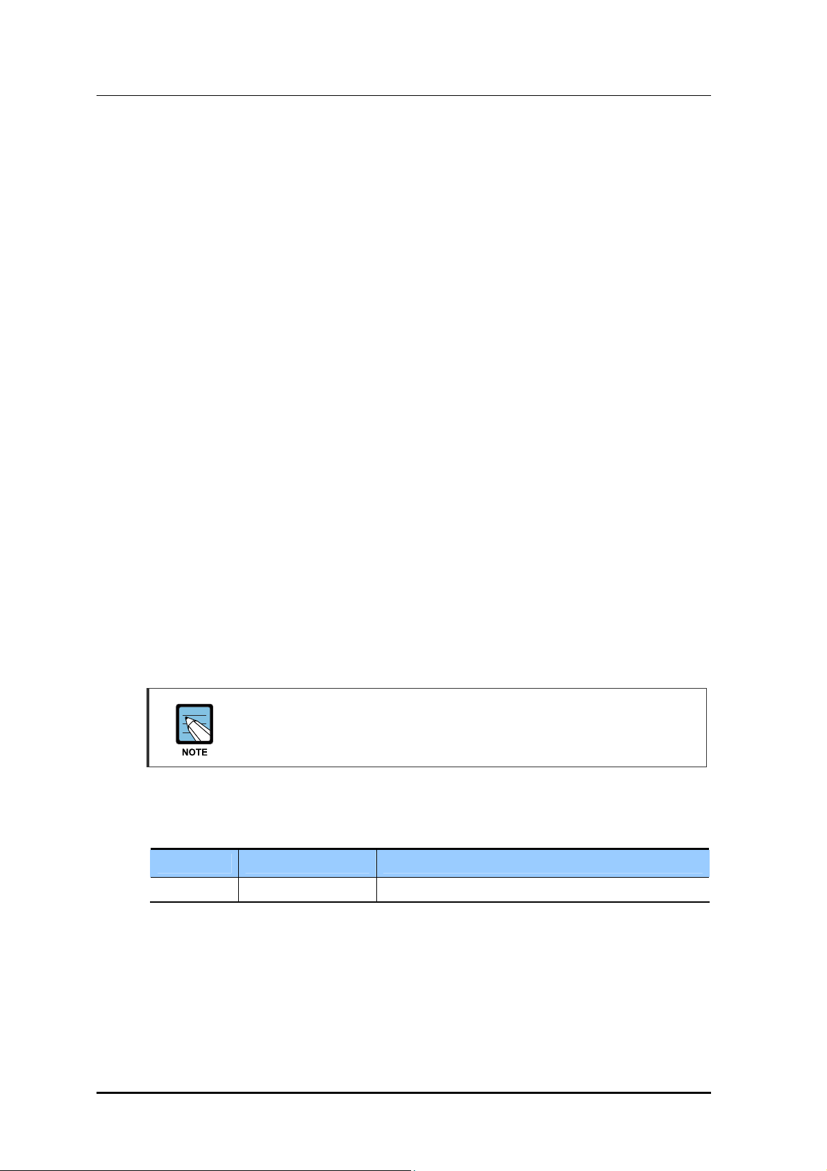
1.3 Mobile WiMAX Network Configuration
Mobile WiMAX network is composed of ASN and CSN. ACR and RAS are involved in
ASN and WSM is the Network Element (NE) to manage ACR and RAS. CSN is composed
of AAA server, HA and PCRF server. ASN is connected with CSN by router and switch.
The following diagram shows the composition of Mobile WiMAX network.
AAA
WSM
RAS
PCRF
MS
HA
ACR ACR
Core Router/Switch
Ed
…
RAS
MS MS MS
RAS
Internet
CSN
e Router/Switch
SN
RAS
Figure 1.1 Mobile WiMAX Network Configuration
Radio Access Station (RAS)
RAS as the system between ACR and MS has the interface with ACR and provides the
wireless connection to MS under IEEE 802.16 standards to support wireless
communication service for subscribers.
RAS carries out wireless signal exchange with MS, modulation/demodulation signal
processing for packet traffic signal, efficient use of wireless resources, packet scheduling
for Quality of Service (QoS) assurance, assignment of wireless bandwidth, Automatic
Repeat request (ARQ) processing and ranging function. In addition, RAS controls the
connection for packet calls and handover.
1-4
© SAMSUNG Electronics Co., Ltd.

Mobile WiMAX RAS SPI-2213 System Description/Ed.00
Access Control Router (ACR)
ACR, which is the system between CSN and RAS, enables several RASs to interwork with
IP network, sends/receives traffic between external network and MS, and controls QoS.
ACR connects to Authentication, Authorization and Accounting (AAA) server and Policy &
Charging Rules Function (PCRF) server in Diameter protocol method and provides the
interface to NE of CSN.
Mobile WiMAX System Manager (WSM)
WSM provides the management environment for the operator to operate and maintain ACR
and RAS.
Home Agent (HA)
HA accesses other networks or private networks and enables Mobile IP (MIP) users to
access internet. HA interworks with ACR that performs Foreign Agent (FA) function for
Mobile IPv4 and interworks with MS to exchange data for Mobile IPv6.
Authentication, Authorization and Accounting (AAA) Server
AAA server interfaces with ACR and carries out subscriber authentication and accounting
functions. The AAA server interfaces with ACR via Diameter protocol and provides
Extensible Authentication Protocol (EAP) certification.
Policy & Charging Rules Function (PCRF) Server
The PCRF server is the server that manages the service policy and interfaces with ACR via
Diameter protocol. The PCRF server sends QoS setting information for each user session
and accounting rule information to ACR.
© SAMSUNG Electronics Co., Ltd. 1-5
CHAPTER 1. Overview of Mobile WiMAX System
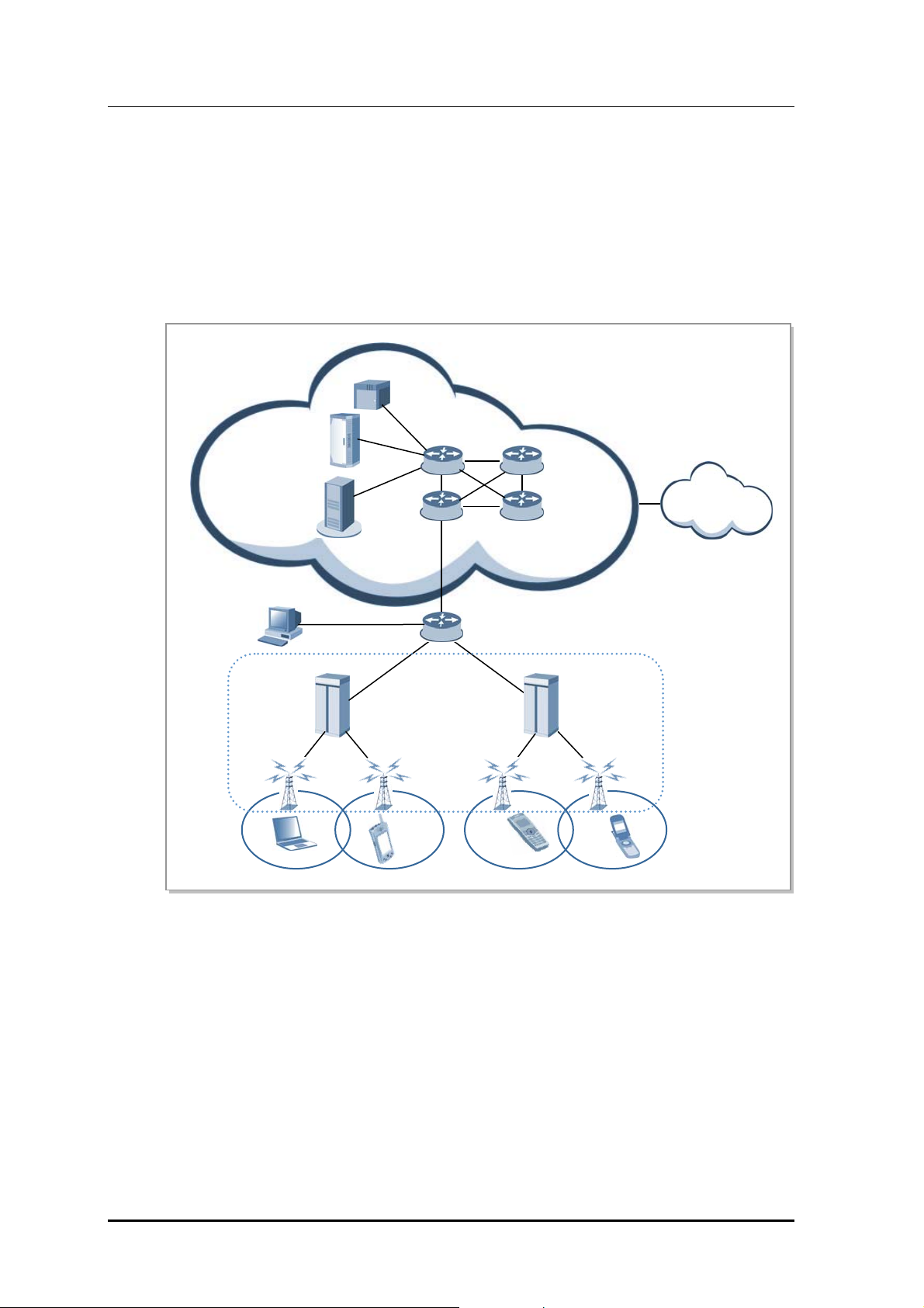
1.4 Mobile WiMAX System Functions
The figure below shows the functions of the ASN systems (ACR and RAS) based on Profile C.
Each block name complies with the standard of Mobile WiMAX NWG.
ASN
ASN GW (ACR)
Paging Controller
Location Register
Context Function
Handover Function
(Handover Relay)
BS (RAS)
Context Function
Handover Function
(Handover Control)
Figure 1.2 Configuration of Mobile WiMAX System Functions (Based on Profile C)
Authenticator
Key Distributor
SFA
AAA Client
R6
Key Receiver
RRC & RRA
SFM
(Admission Control)
MIP FA PMIP client
IP Packet Forwarding
Header Compression
Packet Classification
ARQ Operation
MAC PDU
Encapsulation/PHY
The ACR supports the Convergence Sublayer (CS) and performs the packet classification
and Packet Header Suppression (PHS) functions. When the ACR carries out the header
compression function, it supports Robust Header Compression (ROHC) defined in the
NWG standard.
In addition, the ACR performs the paging controller and location register functions for an
MS in Idle Mode.
In authentication, the ACR performs the authenticator function and carries out the key
distributor function to manage the higher security key by interworking with the AAA server
as an AAA client. At this time, RAS performs the key receiver function to receive the
security key from the key distributor and manage it.
The ACR interworks with the AAA server of CSN for authentication and charging services
and with the HA of CSN for Mobile IP (MIP) service. The ACR as FA of MIP supports
Proxy MIP (PMIP).
1-6
© SAMSUNG Electronics Co., Ltd.

Mobile WiMAX RAS SPI-2213 System Description/Ed.00
The RAS performs the Service Flow Management (SFM) function to create/change/release
connections for each Service Flow (SF) and the admission control function while
creating/changing connections. In regard to the SFM function of the RAS, the ACR carries
out the SF Authentication (SFA) and SFID management functions. The ACR carries out the
SFA function to obtain the QoS information from Policy Function (PF) and apply it in the
SF creation and performs the SFID management function to create/change/release SFID
and map SF according to the packet classification.
In handover, the RAS performs the handover control function to determine the execution of
the handover and deal with corresponding handover signaling. The ACR confirms the
neighbor RAS list and relays the handover signaling message to the target system.
At this time, the ACR and the RAS carries out the context function to exchange the context
information between the target system and the serving system.
The RAS provides Admission Control to collect/manage the MS’s radio resource
information and the RAS’s own radio resource information (e.g., BSID). When load
balancing is required based on Admission Control results, it performs resource
management through FA overriding and BS init HO (Handover).
ASN System Function
For the detailed description about the RAS functions, refer to Chapter 2 of this
system description. For the description about the ACR functions, refer to the
system description for ACR provided by Samsung.
© SAMSUNG Electronics Co., Ltd. 1-7

CHAPTER 1. Overview of Mobile WiMAX System
This page is intentionally left blank.
1-8
© SAMSUNG Electronics Co., Ltd.

Mobile WiMAX RAS SPI-2213 System Description
CHAPTER 2. Overview of SPI-2213
2.1 Introduction to SPI-2213
The SPI-2213, RAS of Mobile WiMAX, is controlled by ACR and connects Mobile
WiMAX calls to MS.
The SPI-2213 interfaces with MS via a wireless channel observing the Mobile WiMAX
standard (IEEE 802.16) and provides high-speed data service and multimedia service in
wireless broadband.
To this end, the SP I-2213 provides the following functions: modulation/d e modulation of
packet traffic si gn a l , sc heduling an d ra d i o b a n dw i d t h a ll o c a t i o n to manage air resources
efficiently and ensure Quality of Service (QoS), Automatic Repeat request (ARQ)
processing, ranging function, connection control function to transmit the information on the
SPI-2213 and set/hold/disconnect the packet call connection, handover control and ACR
interface function and system operation management function.
Physically, the SPI-2213 consists of a Digital Unit (DU) and a Mobile WiMAX base station
Remote Radio Head (RRH).
The RRH is located remotely from the DU. The DU is a digital unit of 19 in. shelf form
and can be installed in an indoor or outdoor 19 in. rack. It supports a capacity up to
2Carrier/3Sector. The DU is operated in omni or sector mode depending on the features of
the installation location.
An RRH is a standalone RF unit. It is installed on an outdoor wall or pole.
The SPI-2213 supports up to 2Carrier/3Sector.
© SAMSUNG Electronics Co., Ltd. 2-1

CHAPTER 2. Overview of SPI-2213
2.2 Characteristics of SPI-2213
The SPI-2331 supports 10 MHz bandwidth per carrier and has a large packet service in
high speed. Other features are as follows.
2.2.1 Application of the OFDMA Method
OFDMA is used to transmit data to several users simultaneously by using the sub-carrier
allocated to each user and transmit data by allocating one or more sub-carriers to a specific
subscriber according to the channel status and the transmission rate requested by a user.
In addition, since it can select the sub-carriers with excellent features for each subscriber
and allocate them to the subscribers when some subscribers divide and use the whole subcarrier, it can raise the data throughput by distributing the resources efficiently.
2.2.2 Separate DU and RRH Structure
As the SPI-2213 consists of a DU and an RRH, it is easy to set up a network and it is easy
to change the network configuration.
For connections between the DU and RRH, data traffic signals and OAM information are
sent/received through the ‘Digital I/Q and C & M’ interface based on the Common Public
Radio Interface (CPRI). Physically, optic cables are used.
Each of the DUs and RRHs receives -48 VDC of power for its operation.
Versatile Network Operation
The RRH cannot operate on its own, but operates by being linked to the DU. The RRH is
highly flexible in its installation, and helps with setting up a network in a variety of
configurations depending on the location and operation method.
Easy Installation
The optic interface component that interfaces with the DU and the RF signal processing
component is integrated into the RRH, which becomes a very small and very light single
unit. Therefore, the RRH can be installed on a wall or pole.
Moreover, as the distance between the RRH and antenna is minimized, the loss of RF
signals due to the antenna feeder line can be reduced so that more enhanced RF receiving
performance than the existing rack-type RAS can be provided.
Natural Cooling
Because the RRH is installed outdoors and has an efficient design, it can radiate heat
efficiently without any additional cooling system. Therefore, no additional maintenance
cost is needed for cooling the RRH.
2-2
© SAMSUNG Electronics Co., Ltd.

Mobile WiMAX RAS SPI-2213 System Description/Ed.00
Loopback Test
The SPI-2213 provides the loopback test function to check whether communication is
normal on the ‘Digital I/Q and C & M’ interface line between the DU and RRH.
Remote Firmware Downloading
The operator can upgrade the RRH and its service by replacing its firmware.
Without visiting the field station, the operator can download firmware to the RRH remotely
using a simple command from the WSM.
In this way, operators can minimize the number of visits to the field station, reducing
maintenance costs and allowing the system to be operated with greater ease.
Monitoring Port
Operators can monitor the information for an RRH using its debug port.
2.2.3 Support of MIMO
The SPI-2213 basically supports MIMO of 2Tx/2Rx RF path. There are methods of MIMO
as follows;
Downlink
Space Time Coding (STC): method for raising reliability of link
Spatial Multiplexing (SM): method for raising data transmission rate
Uplink
Collaborative SM (CSM): method for doubling the frequency efficiency
2.2.4 Support of Frequency Reuse Pattern (FRP)
The SPI-2213 supports FRP N=1 that provides the service to 3-sector by using a carrier and
FRP N=3 that provides the service to 3-sector by using different carriers.
A service provider can efficiently operate its own frequency resources by using the FRP
function.
Providing or not the System Feature and Schedule to Provide the System
Feature
For the providing or not the system feature and schedule to provide the features
described in this system description, see separate document.
© SAMSUNG Electronics Co., Ltd. 2-3

CHAPTER 2. Overview of SPI-2213
2.3 Main Functions
The main functions of the SPI-2213 are as follows:
Physical layer processing function
Call processing function
IP processing functions
Auxiliary device interface function
Convenient operation and maintenance function
2.3.1 Physical Layer Processing Function
OFDMA Ranging
The ranging supported by the OFDMA system is roughly divided by the uplink timing
synchronization method and the contention based bandwidth request method.
Uplink Timing Synchronization
In the uplink timing synchronization method, the SPI-2213 detects the timing error of
the uplink signal by using the ranging code transmitted from MS and transmits the
timing correction command to each MS to correct the transmission timing of the uplink.
The uplink timing synchronization method has initial ranging, periodic ranging,
handover ranging, etc.
Contention Based Bandwidth Request
In the contention based bandwidth request method, the SPI-2213 receives the
bandwidth request ranging code from each MS and allocates uplink resources to the
corresponding MS to enable to transmit the bandwidth request header.
The contention based bandwidth request method has bandwidth request ranging or
something.
Channel Encoding/Decoding
The SPI-2213 carries out the Forward Error Correction (FEC) encoding for the downlink
packet created in the upper layer by using Convolutional Turbo Code (CTC).
On the contrary, it decodes the uplink packet received from the MS after demodulating.
Modulation/Demodulation
The SPI-2213 carries out the FEC encoding for the downlink packet created in the upper
layer and modulates the encoded packet into the QAM signal. In addition, the SPI-2213
demodulates and decodes the uplink packet received from MS.
2-4
© SAMSUNG Electronics Co., Ltd.

Mobile WiMAX RAS SPI-2213 System Description/Ed.00
OFDMA Sub-carrier Allocation
The subchannelization is the process to tie the sub-carriers of OFDMA as a transmission
unit after grouping them by a certain rule. The SPI-2213 performs the subchannelization to
mitigate the interference between cells.
The SPI-2213 maps the column of the modulated downlink QAM symbol structure with
each sub-carrier and carries out the subchannelization when the column of the QAM
symbol structure is transmitted to the MS over the wireless line. In such way, the SPI-2213
transmits the column of the QAM symbol structure to the MS via the sub-carriers pertained
to each subchannel.
DL/UL MAP Construction
The SPI-2213 informs the air resources for the uplink and the downlink to the MS by using
DL/UL MAP. The DL/UL MAP consists of the scheduling information of the SPI-2213 and
includes various control information for the MS.
Power Control
The SPI-2213 carries out the power control function for the uplink signal received from
multiple MSs and then set the power intensity of the uplink signal to a specific level.
The SPI-2213 transmits the power correction command to each MS and then makes the MS
power intensity be the level required in the SPI-2213 when the MS transmits the modulated
uplink signal in a specific QAM modulation method.
Hybrid-ARQ (H-ARQ) Operation
H-ARQ is the physical layer retransmission method using the stop-and-wait protocol.
The SPI-2213 carries out the H-ARQ function and raises data throughput by re-transmitting
or combining the frame from the physical layer to minimize the effect attending to the
change of wireless channel environment or the change in the interference signal level.
MIMO
The SPI-2213 provides the MIMO function as follows according to Mobile WiMAX Wave
2 Profile:
Downlink
Matrix A (STC)
Transmission ratio of the Matrix A or STC is 1 and equal to that of Single Input
Single Output (SISO). However The Matrix A or the STC reduces the error of the
signal received from the MS by raising the stability of the signal received from the
MS by means of the Tx diversity. This technology is, also, effective in low Signal
to Noise Ratio (SNR) and provides excellent performance even when the MS
moves in high speed.
Matrix B (SM, vertical encoding)
Matrix B or SM method raises the effectiveness of the frequency by raising the
transmission ratio in proportion to the number of antenna in comparison with SISO.
This technology is effective when the reception SNR is high.
© SAMSUNG Electronics Co., Ltd. 2-5

CHAPTER 2. Overview of SPI-2213
Uplink
Collaborative SM
Collaborative SM is the technology that doubles the frequency efficiency in view
of the SPI-2213 as two MSs with each individual antenna send data simultaneously
by using the same channel.
2.3.2 Call Processing Function
Cell Initialization Function
The SPI-2213 announces the MAC Management message such as DCD/UCD/MOB_NBRADV to the cell area in service periodically to enable the MS receiving the message to
carry out the appropriate call processing function.
Call Control and Wireless Resource Allocation Function
The SPI-2213 enables an MS to enter to or exit from the network. When an MS enters to or
exit from the network, the SPI-2213 transmits/receives the signaling message required for
call processing via R1 interface with the MS or R6 interface with ACR.
The SPI-2213 allocates various management/transport Connection Identifier (CID)
required for the network entry and service to an MS. When the MS exit from the network,
the SPI-2213 collects and release the allocated CID.
Handover
The SPI-2213 carries out the signaling and bearer processing for inter-sector HO
(Handover), inter-ACR HO and inter-carrier HO. At this time, ACR relays the handover
message between serving RAS and target RAS through the R6 interface.
To minimize the traffic disconnection in inter-RAS HO, the SPI-2213 performs the data
switching function. In handover, the SPI-2213 enables the serving RAS to switch the user
data in queuing to the target RAS and, therefore, the MS to recover the traffic without loss.
Handover Procedure
For the detailed handover procedure, refer to Chapter 4 ‘Message Flow’.
Support of Sleep Mode
Sleep Mode is the mode defined to save the MS power under IEEE 802.16 standard and
indicates the status that air resources allocated to an MS are released when the MS does not
need traffic reception/transmission temporarily. If the MS in Sleep Mode needs the traffic
reception/transmission, the MS returns to the normal status immediately.
Both Idle Mode and Sleep Mode are modes to save the MS power. The Idle Mode release
all service flows allocated to an MS, while the Sleep Mode releases only the air resources
between the MS and RAS temporarily, continuously keeping the service flow information
allocated to the MS.
2-6
© SAMSUNG Electronics Co., Ltd.

Mobile WiMAX RAS SPI-2213 System Description/Ed.00
The SPI-2213 carries out the related call processing function by receiving/sending the
signaling message required for the status transition into Sleep Mode of MS and the return
from the Sleep Mode to Awake Mode of MS.
Admission Control (CAC) Function
If the SPI-2213 receives the call setup request, such as network entry, Quick Connection
Setup (QCS) and handover, from an MS, it monitors the traffic and signaling load for each
subcell and the number of user in Active/Sleep Mode and performs the AC function to
prevent the system overload.
AC can be roughly divided into AC by MS and AC by service flow.
AC by MS
If the number of users who the subcell is in Active/Sleep Mode exceeds the threshold
when the SPI-2213 receives the call setup request from an MS, it rejects the call setup
request of the MS.
AC by service flow
When service flow is added, the SPI-2213 checks if the air resources of the requested
subcell exceed the threshold and determines the creation of the service
MAC ARQ Function
The SPI-2213 carries out the ARQ function of the MAC layer. In packet data exchange, the
transmission side transmits ARQ block which SDU is divided into, and retransmits the
packet according to the ARQ feedback information received from the reception side to
raise the reliability of data communication.
The SPI-2213 carries out the following function for the service flows applying ARQ:
MAC Management creation and transmission concerned with ARQ operation
Feedback processing depending on ARQ types
Block processing (fragmentation/reassemble/retransmission) depending on ARQ types
ARQ timer/window management
QoS Support Function
The packet traffic exchanged between ACR and SPI-2213 is delivered to the modem in the
SPI-2213. At this time, the SPI-2213 allocates the queue in the modem to each service flow
that QoS type is specified to observe the QoS constraint given for each QoS class or service
flow and performs the strict-priority scheduling according to the priority.
The modem that receives the packet traffic performs the scheduling by using the uplink/
downlink algorithm, such as Proportional Fair (PF) or Round Robin (RR) and transmits the
scheduled allocation information to an MS through DL/UL MAP. The MS receiving the
DL/UL MAP checks the air resources allocated to the MS and modulates/demodulates the
downlink packet or transmits the uplink packet from the allocated uplink area.
Since the SPI-2213 provides the QoS monitoring function, it can compile statistics on
packets unsatisfying the latency requested from the QoS parameter according to TDD
frames and report the statistics to an operator via the OAM interface.
© SAMSUNG Electronics Co., Ltd. 2-7
CHAPTER 2. Overview of SPI-2213
2.3.3 IP Processing Functions
IP QoS Function
Since the SPI-2213 supports Differentiated Services (DiffServ), it can provide the backhaul
QoS in the communication with ACR.
It supports 8-class DiffServ and supports the mapping between the DiffServ service class
and the service class of the user traffic received from an MS. In addition, the SPI-2213
supports the mapping between Differentiated Services Code Point (DSCP) and 802.3
Ethernet MAC service class.
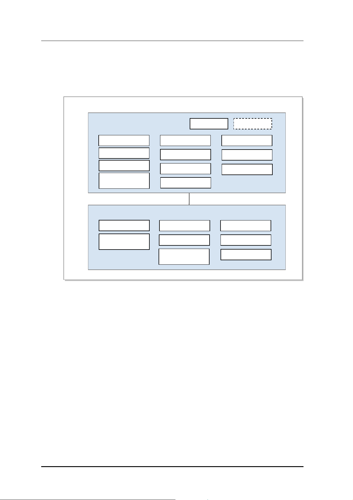
Simultaneous Support of IPv4/IPv6
ACR communicates with the SPI-2213 through the GRE tunnel and the backhaul IP
version between the SPI-2213 and ACR is managed independently from the service IP
version for the MS.
Even if, therefore, IPv4 is used in backhaul between the SPI-2213 and ACR, all of IPv4,
IPv6 and IPv4/IPv6 dual stack services can be supported for the MS.
IPv6 Network
IPv4 Network
Dual Stack MS
(IPv4/IPv6)
RAS
Access Network
IPv4
IPv6
Gateway
Dual Stack Processing
Core Network
ACR
Gateway
Figure 2.1 IPv4/IPv6 Dual Stack Operation
IP Routing Function
Since the SPI-2213 provides several Ethernet interfaces, it stores the routing table with the
information on the Ethernet interface to route IP packets. The routing table of the SPI-2213
is configured depending on operator’s setting and the configuration and the setting of the
routing table are similar to the standard setting of the router.
The SPI-2213 supports the static routing configuration only and not the router function for
the traffic received from the outside. When the SPI-2213 connects an auxiliary device, it
supports the IP packet routing function for the auxiliary device by using Network Address
Translation (NAT).
2-8
© SAMSUNG Electronics Co., Ltd.

Mobile WiMAX RAS SPI-2213 System Description/Ed.00
Ethernet/VLAN Interface Function
The SPI-2213 provides the Ethernet interface and supports the static link grouping function,
Virtual Local Area Network (VLAN) function and Ethernet CoS function under IEEE
802.3ad for the Ethernet interface. At this time, the MAC bridge function defined in IEEE
802.1D is excluded.
The SPI-2213 enables several VLAN IDs to be set in one Ethernet interface and maps the
DSCP value of IP header with the CoS value of Ethernet header in Tx packet to support
Ethernet CoS.
2.3.4 Auxiliary Device Interface Function
The SPI-2213 provides the Ethernet interface to connect auxiliary devices and allocates IP
addresses by operating as a DHCP server for the auxiliary devices. In addition, the SPI2213 provides the traffic path to transmit/receive the maintenance traffic between an
auxiliary device and the remote auxiliary device monitoring server.
If the auxiliary device uses a private IP address, the SPI-2213 carries out the NAT function
to change the address into a public IP address (i.e., the IP address of the SPI-2213) for the
communication with an external monitoring server.
2.3.5 Maintenance Function
The SPI-2213 interworking with the management system carries out the following
maintenance functions: system initialization and restart, management for system
configuration, management for the operation parameters, failure and status management for
system resources and services, statistics management for system resources and various
performance data, diagnosis management for system resources and services and security
management for system access and operation.
Graphic and Text-based Console Interface
WSM manages the entire Mobile WiMAX system by using Database Management System
(DBMS) and SPI-2213 interworks with this WSM. In addition, ACR interworks with the
console terminal for directly accessing the NE as well as WSM by operator to perform the
operation and maintenance function.
For operator’s convenience and working purpose, the operator can select graphic-based
console interface (Web-based Element Maintenance Terminal, Web-EMT) or text-based
console interface (Integrated Management Interface Shell, IMISH).
The operator can access the console interface with no separate software and log in to WebEMT through Internet Explore and IMISH through Secure Shell (SSH) on the command
window.
The operator can carry out the retrieval and setup of the configuration and the operation
information and monitoring about faults, status and statistics via console terminal.
However, the operator can carry out grow/degrow of resources and setting of the neighbor
list and paging group which have correlation between several NEs only via the WSM.
© SAMSUNG Electronics Co., Ltd. 2-9

CHAPTER 2. Overview of SPI-2213
Operator Authentication Function
The SPI-2213 provides the authentication and the permission management functions for the
operator who manages the Mobile WiMAX system. The operator accesses the SPI-2213 by
using the operator’s ID and password via Web-EMT or IMISH and the SPI-2213 assigns
the operation right in accordance with the operator’s level.
The SPI-2213 carries out the logging function for successful access, access failure and
login history.
Maintenance Function with Enhanced Security Function
For the security, the SPI-2213 supports Simple Network Management Protocol version 2c
(SNMPv2c) Simple Network Management Protocol version 3 (SNMPv3) and File Transfer
Protocol (FTP) in the communication with WSM and Hyper Text Transfer Protocol over
SSL (HTTPs) and Secure Shell (SSH) in the communication with console terminals.
On-line Software Upgrade
When a software package is upgraded, the SPI-2213 can upgrade the package while running
old version of software package. The package upgrade is progressed in the following
procedure: ‘Add New Package Change to New package Delete Old Packa ge’.
In package upgrade, the service is stopped temporarily because the old process is terminated
and the new process is started in the ‘Change to New package’ stage.
However, since OS is not restarted, the service will be provided again within a few minutes.
After upgrading software, the SPI-2213 updates the package stored in a non-volatile storage.
In addition, the SPI-2213 can re-perform the ‘Change to New package’ stage to roll back
into the previous package before upgrade.
2-10
Call Trace Function
The SPI-2213 supports the call trace function for a specific MS. The SPI-2213 can carry
out the call trace function up to 10 MSs. If a call occurs in the MS that an operator
previously specified via ACR, the signaling message and statistical traffic data are
transmitted to WSM. Besides, the SPI-2213, also, sends the RF environment information,
such as Carrier-to-Interference-and-Noise-Ratio (CINR) for MS, Modulation and Coding
Schemes (MCS) level and Burst Error Rate (BER).
© SAMSUNG Electronics Co., Ltd.
Mobile WiMAX RAS SPI-2213 System Description/Ed.00
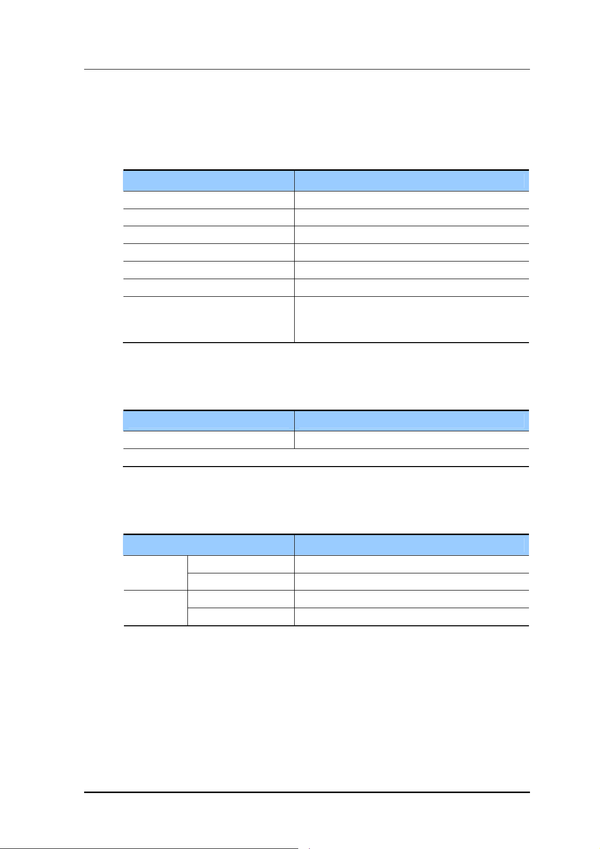
2.4 Specifications
Capacity
The capacity of the SPI-2213 is as follows:
Category System Capacity
Channel Bandwidth 5MHz / 10 MHz
RF Band 2,590~2,690 MHz (100 MHz, UBS)
Maximum Number of Carriers/Sectors 2Carrier/3Sector
Interface between ACR and SPI-2213 Select one of Fast Ethernet and Gigabit Ethernet
FFT size/Carrier/Sector 1,024
Channel Card Capacity 1Carrier/1Sector
Output Antenna Port-based
- 4 W/Carrier/Path @ 10 MHz, MIMO
- 2 W/Carrier/Path @ 5 MHz, MIMO
Input Power
The table below lists the power standard for the SPI-2213.
Category Standard
System Input Voltage
a) Each of the DU and RRH receives -48 VDC of power for its operation.
a)
-48 VDC (Voltage Variation Range: -40~-56 VDC)
Unit Size and Weight
The table below lists the size and weight of the SPI-2213.
Category Standard
DU 432 (W) × 396 (D) × 200 (H) Size (mm)
RRH 295 (W) × 135 (D) × 410 (H)
Weight (kg)
DU
RRH
20 or less
15 or less
© SAMSUNG Electronics Co., Ltd. 2-11

CHAPTER 2. Overview of SPI-2213
Environmental Condition
The table below lists the environmental conditions and related standards such as
operational temperature and humidity.
DU
Category Range
Temperature Conditiona) 0~50°C (32~122°F)
Humidity Conditiona) 10~90% but not to exceed 0.024 kg water/kg of dry air
Altitude 0~1,800 m (0~6,000 ft)
Vibration GR-63-CORE Sec.4.4
Sound Pressure Level Less than 65 dBA measured at points 1.5 m (59.1 in) above the floor
EMI FCC Title47 Part 15 Class A
Earthquake
Office Vibration
Transportation Vibration
and 0.6 m (23.6 in) all around.
GR-1089-CORE Sec. 3.2 Emission Criteria
a) The standards of temperature/humidity conditions are based on the value on the position where is
400 mm (15.8 in.) away from the front of the DU and in the height of 1.5 m (59 in.) on the bottom.
RRH
Category Range
Temperature Conditiona) -40~50°C (-40~122°F)
Humidity Conditiona) 10~95% but not to exceed 0.024 kg water/kg of dry air
Altitude 0~1,800 m (0~6,000 ft)
Vibration GR-63-CORE Sec.4.4
Earthquake
Office Vibration
Transportation Vibration
Sound Pressure Level Less than 65 dBA measured at 1.5 m (5 ft) from the RRH in all
horizontal directions at a height of 1 m (3 ft)
EMI FCC Title47 Part 15 Class B
GR-1089-CORE Sec. 3.2 Emission Criteria
US Federal Regulation FCC Title47 Part27
a) The standards of temperature/humidity conditions are based on the value on the position where is
400 mm (15.8 in.) away from the front of the RU and in the height of 1.5 m (59 in.) on the bottom.
2-12
© SAMSUNG Electronics Co., Ltd.

Mobile WiMAX RAS SPI-2213 System Description/Ed.00
Environmental Alarm
The table below lists the environmental alarm provided in the SPI-2213 in default.
Category Description
Temperature Alarm
Fan Fail
High Temperature
System Fan Fail
GPSR Specification
The table below lists the GPS Receiver (GPSR) characteristics of SPI-2213.
Category Description
Received Signal from GPS GPS L1 Signal
Accuracy/Stability 0.02 ppm
RF Specification
The table below lists the RF characteristics of the SPI-2213.
Category Description
Tx Output Power
Tx Constellation error
8 W @avg power per carrier/sector (10MHz Bandwidth)
4 W @avg power per carrier/sector (5MHz Bandwidth)
In accordance with the 802.16e standard
RX Sensitivity
In accordance with the 802.16e standard
© SAMSUNG Electronics Co., Ltd. 2-13

CHAPTER 2. Overview of SPI-2213
2.5 System Configuration
Physically, the SPI-2213 consists of a DU and RRHs.
The boards that make up the DU are mounted on the SMFS-F, which is a 19 in. indoor shelf.
The SMFS-F can be mounted on a 19 in. indoor or outdoor commercial rack.
Samsung Mobile WiMAX Flexible Shelf assembly-Front mount (SMFS-F)
Shelf for DU of SPI-2213
Mounting is supported when mounted on a 19 in. rack.
SMFS-F
FAN- FD48 DMB DPM-FI
DPM-FI DC Power Module-Flexible Indoor
DMB Digital Main Block
FAN-FD48 FAN Module-Flexible Digital unit -48 VDC
Figure 2.2 DU Configuration (SMFS-F)
2-14
© SAMSUNG Electronics Co., Ltd.

Mobile WiMAX RAS SPI-2213 System Description/Ed.00
The RRH is a single unit that can be installed on a wall or pole without an additional shelf
or rack.
A
A
B
B
Figure 2.3 RRH Configuration
© SAMSUNG Electronics Co., Ltd. 2-15

CHAPTER 2. Overview of SPI-2213
2.6 Interface between Systems
2.6.1 Interface Structure
The SPI-2213 interfaces with another RAS and ACR as shown in the figure below:
HA
ASN
RAS
ACR
R4
RAS
SNMP, FTP
WSM
AAA PCRF
CSN
R3 (Diameter, MIP)
ACR
R6
R6
R8
SPI-2213
R1 (802.16e)
MS
Figure 2.4 Structure of SPI-2213 Interface
2-16
Interface between SPI-2213 and MS
The SPI-2213 interfaces with an MS according to the IEEE 802.16 radio access standard to
exchange the control signal and the subscriber traffic.
Interface between SPI-2213 and ACR
The interface between an ACR and the SPI-2213 in the same ASN is R6 and its physical
access method is GE/FE. The R6 is the interface between ACR and RAS defined in Mobile
WiMAX NWG and is composed of signaling plane (IP/UDP/R6) and bearer plane
(IP/GRE).
Interface between SPI-2213 and WSM
The interface between the SPI-2213 and the WSM complies with SNMPv2c or
SNMPv2c/SNMPv3c of IETF standard, FTP/SFTP and proprietary standard of Samsung
and its physical access method is GE/FE.
© SAMSUNG Electronics Co., Ltd.

Mobile WiMAX RAS SPI-2213 System Description/Ed.00
6
6
A
A
2.6.2 Protocol Stack
Protocol Stack between NEs
The figure below shows the protocol stack between NEs.
802.16
MAC
802.16
PHY
MS RAS ACR
802.16
MAC
802.16
PHY
PHY
GRE
(R6)
16
R
UDP
IP
L2
L1
GRE
(R6)
R
UDP
IP
L2
L1
L2
L1
Figure 2.5 Protocol Stack between NEs
The SPI-2213 interworks with MSs via R1 interface according to IEEE 802.16 standard
and the interface between the SPI-2213 and ACR is R6 interface.
The R6 signaling interface is executed on UDP/IP and the R6 traffic interface uses the GRE
tunnel.
Protocol Stack for Operation and Maintenance
RAS
WSM
FTP
SSH
TCP
pplication
SNMP
UDP
IP
L2
L1
UDP
pplication
SNMP
IP
L2
L1
FTP
SSH
TCP
Figure 2.6 Protocol Stack between SPI-2213 and WSM
The ACR interworks with WSM in IP/UDP-based SNMP method to carry out the operation
and maintenance functions. In particular, the SPI-2213 interworks with WSM in IP/TCPbased FTP/SFTP (FTP over SSH) method to collect the statistical data periodically,
initialize & restart the system and download software.
© SAMSUNG Electronics Co., Ltd. 2-17

CHAPTER 2. Overview of SPI-2213
2.6.3 Physical Interface Operation Method
The SPI-2213 provides Ethernet interface as an ASN interface and can select the type of
interfaces depending on the network configuration. At this time, more than one type of
interfaces cannot be operated simultaneously. The number of interfaces can be optionally
managed depending on the capacity and the required bandwidth of the SPI-2213.
The types of interfaces are as follows:
Ethernet
Interface Type
100/1000Base-T (RJ-45) 4 4
1000BaseX (SFP)
100/1000Base-T (RJ-45)
(Simultaneous operation)
Number of Ports per
Board
2 2
2 2
Number of Ports per
System
Ethernet interface operate several links as 802.3ad (static)-based static link aggregation.
The operation and maintenance interface (interface with WSM) is operated in in-band
method, which shares the common user traffic interface.
2-18
© SAMSUNG Electronics Co., Ltd.

Mobile WiMAX RAS SPI-2213 System Description
CHAPTER 3. SPI-2213 Architecture
3.1 System Configuration
3.1.1 DU and RRH
The SPI-2213 has a separate structure consisting of a DU and RRHs.
Because up to three RRHs can be connected to a DU, the maximum 2Carrier/3Sector
MIMO service is possible.
DU
The DU is composed of a Digital Main Block (DMB), DPM-FI, and FAN-FD48.
DMB
The DMB operates and maintains the SPI-2213, enables the SPI-2213 to interface with
ACR and provides the communication path between processors in the system.
The DMB creates the reference clock, provides the clock to the lower hardware block
and performs the signal processing function for the subscriber signal.
The DMB also interfaces with the RRH to send and receive data traffic, and receives
and controls alarms for the lower hardware blocks or modules, including the RRH.
DPM-FI
The DPM-FI receives DC power through a separate rectifier and distributes it to every
board and module on the DU shelf. The operator can control DC power supply by
turning the circuit breaker at the front of the DPM-FI on/off.
FAN-FD48
The FAN-FD48 is composed of a set of four fans and maintains the inside temperature
of the DU within an appropriate range so that the SPI-2213 can operate normally.
The FAN-FD48 detects the inside temperature of the DU using a built-in temperature
sensor and sets the speed of the fan in accordance with the detected temperature.
© SAMSUNG Electronics Co., Ltd. 3-1

CHAPTER 3. SPI-2213 Architecture
RRH
The RRH is a unified RF module interfacing remotely with the DU through an optical
cable. It is located at the front end of the antenna.
On a downlink, it converts the data traffic in the form of ‘Digital I/Q and C & M’ received
from the MRA-F of the DU into RF signals, which have up to 8W/carrier/sector output,
and then sends them through an external antenna.
Conversely, on an uplink, the RRH converts the RF signals received through the antenna
into ‘Digital I/Q and C & M’ data traffic, and then sends them to the MRA-F of the DU.
The RRH also receives clock information from the DU through the ‘Digital I/Q and C & M’
interface, and sends/receives alarm/control messages.
3-2
© SAMSUNG Electronics Co., Ltd.

Mobile WiMAX RAS SPI-2213 System Description/Ed.00
3.1.2 Internal Configuration of the System
Below are the internal configuration diagrams of the SPI-2213 (2Carrier/3Sector).
Rectifier*
DU
DPM-FI
F
A
N
F
D
48
-
MEI-B
α
RET
R
R
H
(0)
M
R
A
F
(0)
β
RET
R
R
H
(1)
γ
RET
R
R
H
(2)
GPS
M
R
-
A
-
F
(1)
M
R
A
F
(2)
M
R
-
A
-
F
(3)
M
R
A
F
(4)
M
R
-
A
-
F
(5)
MMA-G
Ethernet
FE/GE
ACR
UDA
Index
Data Traffic + Alarm/Control + Clock(Ethernet)
Alarm/Control Power
Digital I/Q and C & M(Optic) Clock
Optional Item Backhaul
* Rectifier is not provided by Samsung.
Figure 3.1 Internal Configuration of the System (RRH-2)
© SAMSUNG Electronics Co., Ltd. 3-3

CHAPTER 3. SPI-2213 Architecture
3.2 Detailed Structure
3.2.1 Digital Main Block (DMB)
The DMB supports the operation and maintenance of the SPI-2213, interfacing between the
SPI-2213 and ACR, and interfacing between the DU and RRH. It also collects and controls
alarms for the lower boards and modules, including the inter-processor communication
paths and RRH in the system. The DMB also generates and supplies clocks to the lower
hardware blocks, including the RRH, and processes channels for subscriber signals.
When the SPI-2213 sends signals to an MS, the DMB performs the OFDMA signal
processing on the traffic signals received from the ACR, converts them into optical signals
using the ‘Digital I/Q and C & M’ converter, and then sends them to the remote RRH.
Conversely, when the SPI-2213 receives signals from an MS, the DMB receives ‘Digital
I/Q and C & M’ signals from the remote RRH, performs the OFDMA signal processing on
them, and then sends them to the ACR.
Main Functions
Creation and distribution of the reference clock
Fast Ethernet/Gigabit Ethernet interface with ACR
Fault diagnosis and alarm collection and control
Alarm report
Channel resource management
OFDMA signal processing
Automatic Gain Control (AGC) for the received RF signal and Received Signal
Strength Indicator (RSSI) support
Supporting optical interfacing with the RRH and loopback test
3-4
© SAMSUNG Electronics Co., Ltd.

Mobile WiMAX RAS SPI-2213 System Description/Ed.00
The DMB is configured as shown in the figure below:
DMB
MRA-F(5)
MRA-F(4)
MRA-F(3)
MRA-F(2)
MRA-F(1)
MRA-F(0)
MMA-G
MEI-B
Figure 3.2 DMB Configuration
Board Name
Quantity
(Sheet)
Function
MBB-F 1 Mobile WiMAX base station Backplane Board-Flexible
- DMB backboard
- Signal routing function for traffic, control signal, clock, power, etc.
MMA-G 1 Mobile WiMAX base station Main control board Assembly-General
- Main system processor
- Call processing, resource allocation and OAM
- Reception of the GPS signal and creation and supply of the clock
- Alarm collection and report to the upper
- Supports FE/GE interface with ACR
- Non-volatile memory support
MRA-F Max. 6 Mobile WiMAX base station RAS board Assembly-Flexible
- Subscriber data traffic processing
- OFDMA Processing
- 1Carrier/1Sector MIMO
- ‘Digital I/Q and C & M’ data formatting
- Supporting optical interfacing with the RRH (E/O, O/E conversion)
- Supporting loopback tests between the DU and the RRH
MEI-B 1 Mobile WiMAX base station External Interface board assembly-Basic
- Provides User Defined Alarm (UDA)
- Alarm monitoring including fan alarm/high temperature
© SAMSUNG Electronics Co., Ltd. 3-5

CHAPTER 3. SPI-2213 Architecture
Mobile WiMAX base station Main control board Assembly-General (MMA-G)
The MMA-G provides a main processor function of the SPI-2213, GPS signal receiving
and clock distribution, and network interface functions.
Main Processor Function
The MMA-G is the board that carries out the role as the highest layer in the SPI-2213
and is equipped with the main processor. The main processor of the MMA-G performs
the functions, such as communication path setting between MS and ACR, Ethernet
switch function in the SPI-2213, system operation and maintenance and TDD signal
control.
The MMA-G manages the status of all hardware and software in the SPI-2213 and
reports each status information to WSM via ACR. In addition, the MMA-G allocates
and manages the resources of the SPI-2213 and the connection of the MMA-G and a
PC for the Web-EMT enables to maintain the SPI-2213 with no interworking with
ACR.
GPS Signal Reception and Clock Distribution Function
The MMA-G is equipped with Universal Core Clock Module (UCCM) for GPS signal
reception.
The UCCM enables each block of the SPI-2213 to be operated in the synchronized
clock system. The UCCM mounted on the MMA-G creates the system clocks [56
MHz, 12.5 Hz (80 msec), PP2S, analog 10 MHz, 61.44 MHz] by using the reference
signal received from a GPS and distributes them to the hardware blocks in the system.
These clocks are used to maintain the internal synchronization of the SPI-2213 and
operate the system.
If no GPS signal is received due to a fault when system operation, the UCCM carries
out the holdover function to provide the normal clock for a certain time as provided in
the existing system.
Network Interface Function
The MMA-G interfaces with an ACR in Gigabit Ethernet or Fast Ethernet method.
The MMA-G can provide maximum two Gigabit Ethernet ports or four Fast Ethernet
ports per board, and support the link aggregation redundancy method.
The MMA-G can be divided as follows depending on the interface types provided by
MMA-G, and service provider can choose the interface type.
MMA-GC: Four 100/1000Base-T Copper ports
MMA-GM: Two 100/1000Base-T ports and two 1000Base-X Small Form factor
Pluggable (SFP) ports
3-6
© SAMSUNG Electronics Co., Ltd.

Mobile WiMAX RAS SPI-2213 System Description/Ed.00
Mobile WiMAX base station RAS board Assembly-Flexible (MRA-F)
The MRA-F provides a modem function of the SPI-2213 and interfacing with the RRH.
Modem Function
The MRA-F is equipped with the modem supporting IEEE 802.16 Mobile WiMAX
standard physical layer (PHY) and the modem performs the OFDMA signal processing
function by the control of the MMA-G.
The MRA-F modulates the packet data received through the MMA-G, converts the
modulated signal into the ‘Digital I/Q and C & M’ format and transmits to the RRH.
In the contrary, the MRA-F demodulated the data received from the RRH after
performing the AGC function, converts the data into the format defined in the IEEE
802.16 Mobile WiMAX physical layer standard and then transmits the converted data
to the MMA-G via Ethernet.
The MRA-F supports 1Carrier/1Sector 2 × 2 MIMO by default.
Optical interfacing with the RRH and Loopback Test
As the MRA-F contains a built-in Electrical to Optic (E/O) conversion device and an
Optic to Electrical (O/E) conversion device, it can send and receive ‘Digital I/Q and C
& M’ signals of the optical signals between distant RRHs.
The MRA-F can also run loopback tests to check whether the interface between the
MRA-F and RRHs is in good condition for proper communication.
The operator can run the loopback test if necessary using the WSM command.
Mobile WiMAX base station External Interface board assembly-Basic (MEI-B)
The MEI-B provides paths for alarm information that is generated from external devices
(additional equipment provided by the operator).
The MEI-B also collects alarms for the fan mounted on the DU to report to the MMA-G.
3.2.2 RRH
The RRH is a remote RF device that supports Mobile WiMAX services.
It is installed at a remote location from the DU. It performs the function that connects
mobile WiMAX calls to an MS, as defined in the 802.16d/e standard.
Main Functions
Below are the major functions of the RRH.
High-power amplification of RF transmission signal
Interfaces optically with the MRA-F of the DU using ‘Digital I/Q and C & M’ and
carries out interfacing for traffic, alarms, control signals, and clock information.
Upconversion/downconversion of frequency
Gain control of RF Rx/Tx signal
Rx/Tx RF signal from/to an antenna
Suppression of out-of-band spurious wave emitted from RF Rx/Tx signal
Low noise amplification of band-pass filtered RF Rx signal (Low Noise Amplifier, LNA)
TDD switching function for Tx/Rx path
Includes the filter part connected to the antenna
© SAMSUNG Electronics Co., Ltd. 3-7

CHAPTER 3. SPI-2213 Architecture
RRH Description
The RRH is a RF module of the SPI-2213, and supports sending/receiving RF paths.
RRH of this system is as follows:
Category EA Capacity RF Path Antenna Output
RRH-2 Max. 3 2Carrier/1Sector
(Contiguous 2Carriers)
MIMO (2Tx/2Rx) Outputs 4W/Sector/Carrier at 2
antenna ports each(10MHz B/W)
Outputs 2W/Sector/Carrier at 2
antenna ports each(5MHz B/W)
The RRH is an RRH that integrates the RAS transceiver, power amplifier, TDD switch, and
filters in a single module.
In the case of downlink signals, the RRH converts baseband signals received through the
‘Digital I/Q and C & M’ interface from the MRA-F into Optic to Electrical (O/E).
The converted signals undergo Digital to Analog Conversion (DAC) to be converted to
analog RF signals, and then are amplified through the current amplification process.
Amplified signals are sent to the antenna via the filter part.
In the case of uplink signals, the frequency of the signals received through the RRH filter
part is lowered by Low Noise Amplifier (LNA). The Analog to Digital Conversion (ADC)
process converts these signals to baseband signals. The baseband signals are in the ‘Digital
I/Q and C & M’ format, and undergo E/O conversion to be sent to the MRA-F.
3-8
© SAMSUNG Electronics Co., Ltd.

Mobile WiMAX RAS SPI-2213 System Description/Ed.00
Network Configuration Using the RRH
The RRH cannot operate on its own, but operates by being linked to the DU. The RRH is
highly flexible in its installation, and helps with setting up a network in a variety of
configurations depending on the location and operation method as shown below.
β Sector
γ Sector
α Sector
2 Carrier/3 Sector
RRH-2 for 2Tx/2Rx
Figure 3.3 Sector Configuration Example Using RRH-2
Conditions for Sector Configuration Using RRH-2
2carrier supported by the RRH-2 must be a contiguous type.
© SAMSUNG Electronics Co., Ltd. 3-9

CHAPTER 3. SPI-2213 Architecture
2Carrier/Omni
2Carrier/Omni
2 Carrier/3 Sector
RRH-2 for 2Tx/2Rx
2Carrier/Omni
Figure 3.4 Omni Configuration Example Using RRH-2
Conditions for Omni Configuration Using RRH-2
- Multiple cells connected to a single DU must belong to a single paging group.
- Omni cells must be independent, and not be adjacent to each other.
- 2carrier supported by the RRH-2must be a contiguous type.
3-10
© SAMSUNG Electronics Co., Ltd.

Mobile WiMAX RAS SPI-2213 System Description/Ed.00
3.2.3 DPM-FI
The DPM-FI is mounted to the right of the SPI-2213 DMB.
DPM-FI
Figure 3.5 DPM-FI Configuration
Board Name Quantity Function
DPM-FI 1 DC Power Module-Flexible Indoor
Receives DC power through a rectifier and distributes it to every block
in the DMB
Every board of the DMB and the fan (FAN-FD48) of the DU in the SPI-2213 receive
power through the MBB-F.
Each board of DMB receives -48 VDC and converts it to the required voltage.
© SAMSUNG Electronics Co., Ltd. 3-11

CHAPTER 3. SPI-2213 Architecture
The following power diagram shows DU input power that is supplied to DPM-FI and
connection points to each board.
Rectifier
DU
DPM-FI
M
E
I
-
B
M
M
A
G
-48 VDC (-40~-56 VDC)
Filter
Circuit Breaker
MBB-F
F
M
M
M
M
M
M
R
A
-
F
#
0
R
R
A
A
-
F
F
#
#
2
1
R
R
A
A
-
F
F
#
#
4
3
A
R
N
A
-
F
F
D
4
#
8
5
3-12
Figure 3.6 Power Structure of SPI-2213
RRH Power Supply
If the RRH is distant from the DU, it is supplied with separate power (e.g., rectifier)
of -48 VDC (-40~-56 VDC).
© SAMSUNG Electronics Co., Ltd.

Mobile WiMAX RAS SPI-2213 System Description/Ed.00
3.2.4 Cooling Structure
DU
The DU of the SPI-2213 maintains the inside temperature of the shelf at an appropriate
range using a set of system cooling fans (FAN-FD48), so that the system can operate
normally when the outside temperature of the DU shelf changes.
FAN-FD48
Figure 3.7 Fan Configuration
Board Name Quantity Function
FAN-FD48 1 FAN Module-Flexible Digital unit -48 VDC
DU cooling fan
The cooling structure of the DU in the SPI-2213 is as follows.
Figure 3.8 Cooling Structure of the DU
The FAN-FD48 has a built-in temperature sensor.
RRH
The RRH of the SPI-2213 is designed with a natural cooling system that supports an outdoor
environment with no additional fan or heater.
© SAMSUNG Electronics Co., Ltd. 3-13

CHAPTER 3. SPI-2213 Architecture
3.2.5 Interface Structure
The layout of SPI-2213 interfaces is as shown in the figure below:
MIMO Support
DU
FAN Alarm from FAN-FD 48
High Temp. Alarm form Temp. Sensor
Open/Short for UDA
-48 VDC
2Tx ports to Antenna
2Rx ports from Antenna
RF output monitoring
RS-232 for Debug
TDD Signal Output
-48 VDC input
DC Power to RET
External Alarm
&
Control
MEI-B
DPM-FI
Power Filter
&
Distribution
RF Processing
Power Module
Main Processing
Clock Processing
Processing
and C & M path
E/O, O/E conversion
E/O, O/E conversion
Digital I/Q and
C & M path
RET Relay
RRH
MMA-G
Baseband
Digital I/Q
MRA-F
FE to Console
RS-232 for Debug port
From GPS Ant
Analog 10 MHz Output
RS-232 for Debug
Digital I/Q and C & M(Optic)
From/to RRH
Digital I/Q and C & M(Optic)
from/to MRA-F
TDD Clock Output
Figure 3.9 Interfaces of SPI-2213 (MIMO)
The SPI-2213 supports MIMO and provides the administrator with the following external
interface.
3-14
External Interface of DU
Category Interface Type Port No. Connector Type
Backhaul
X and 100/1000Base-TX
2 1000 Base-X: SFP (LC) Simultaneous operation of 1000Base-
2 100/1000 Base-Tx: RJ-45
100/1000 Base-TX 4 RJ-45
GPS Antenna Analog RF 1 SMA
RRH interface Digital I/Q and C & M Max. 6 SFP (Single mode)
External Interface of RRH-2
Category Interface Type Port No. Connector Type
TX coupling port Analog RF 2 SMA
Antenna Interface Analog RF (Main Traffic) 2 N-type
DU interface Digital I/Q and C & M 1 Optic (LC)
Power DC power (-48 VDC) 1 Circular Connector
© SAMSUNG Electronics Co., Ltd.

Mobile WiMAX RAS SPI-2213 System Description/Ed.00
3.3 Software Structure
3.3.1 Basic Structure
The components of the SPI-2213 software are shown below: Operating System (OS), Device
Driver (DD), Middleware (MW), Network Processor Software (NPS), IP Routing Software
(IPRS), and application. The application is divided by Call Control (CC) block for the call
processing and the OAM block for operation and maintenance of the SPI-2213.
APPLICATION
CC
MW IPRS
NPS
OS DD
OAM
Hardware
Figure 3.10 Software Structure of SPI-2213
Operating System (OS)
OS initializes and controls the hardware device, and runs the software operation in the
hardware. To operate the software, OS uses the embedded Linux OS, and manages the dual
software processes. Then, OS provides various functions efficiently with limited resources.
Middleware (MW)
MW helps the smooth operation between OS and application under various types of
hardware environment, and to achieve this, MW provides various services: message
delivery service between applications, event notification service, debugging utility services.
In addition, the MW provides the systematic and strong management of the account, the
authority and the authentication function.
Device Driver (DD)
DD manages the normal operation of applications that OS does not control in the system.
DD provides the API for the user processor to setup/control/detect the hardware device.
Also, DD confirms the device configuration by receiving the configuration data from the
upper user processor, and also provides the functions of register manipulation for device
operation, device diagnosis, statistics and status management.
© SAMSUNG Electronics Co., Ltd. 3-15

CHAPTER 3. SPI-2213 Architecture
Network Processor Software (NPS)
NPS manages the innate functions of Network Processor (NP) that mainly processes the
packets, and it connects the upper processor and NP in Board Processor (BP), and provides
the functions of NP message processing, NP statistics data collection and report.
IP Routing Software (IPRS)
IPRS executes the IP routing protocol function. IPRS collects and manages the system
configuration and status data necessary for IP routing operation, and based on the data, it
generates the routing table via the routing protocol, and makes packet forwarding possible.
Call Control (CC)
CC is a software subsystem that processes the calls in the SPI-2213, and CC interfaces with
MS and ACR. CC supports data exchange function to support wireless data service such as
the MAC scheduling, air link control, ARQ processing and IEEE 802.16 message processing.
Operation And Maintenance (OAM)
The OAM provides the interface (SNMPv2c/SNMPv3, FTP/SFTP, HTTPs, SSH) of which
the security is strengthened, and which is standardized to interwork with the upper
management system such as the WSM, the Web-EMT and console terminal based on the
IMISH.
In addition, this performs the functions of initializing and restarting the system, collecting
the statistics for processing the call and various performance data, managing the system
configuration and resources, managing the status of the software resources and the
hardware resources, managing the failure and performing the diagnostics for the operation
and the management of the SPI-2213.
3-16
© SAMSUNG Electronics Co., Ltd.

Mobile WiMAX RAS SPI-2213 System Description/Ed.00
3.3.2 Call Control (CC) Block
The CC block caries out the resource management function of the SPI-2213 and the BS
function of ASN Profile-C defined in NWG of Mobile WiMAX forum. The CC block
consists of RAS Resource Controller (RRC), RAS Service Controller (RSC) and RAS
Traffic Controller (RTC) sub-blocks and the functions of each sub-block are as follow:
CC
MMA-G
RRC
1) RAS signaling interface
2) RAS state monitoring
MRA-F
RSC
1) RAS signaling interface
2) Modem control interface
Figure 3.11 CC Block Structure
RTC
1) RAS traffic interface
2) Modem traffic interface
RRC as the resource manager of the SPI-2213 exchanges the status information with all
blocks and assigns appropriate software resources to a service when it receives the
necessary service request from RAS/ACR.
RSC processes the MAC signaling via R1 interface and interworks with ACR via R6
interface. RSC performs the Call Admission Control (CAC) in the service creation process
and requests the traffic channel setup to RTC. In addition, RSC transfers the information on
the internal control message to the modem block in the SPI-2213.
RTC fragments the user data received from ACR via the R6 interface in MAC PDU format
and transfers the data to the modem block or re-assembles the MAC PDU received from an
MS via the R1 interface and transmits to ACR. In addition, the RTC interworks with the
RSC block controlling the RAS signal and performs the call setup/release procedure.
3.3.2.1 RAS Resource Controller (RRC)
RRC is in charge of the resource management of the SPI-2213 and is activated on the
MMA-G. The RRC interfaces with ACR outside the system and the RSC and OAM blocks
inside the system.
Main functions of RRC are as follows:
ACR Keep Alive
RSC Keep Alive
Inter Carrier Load Balancing
Paging Message Transmission
System Resource Management
© SAMSUNG Electronics Co., Ltd. 3-17

CHAPTER 3. SPI-2213 Architecture
3.3.2.2 RAS Service Controller (RSC)
The RSC is in charge of the signaling-concentrated service in the SPI-2213.
As for the system outside, the RSC performs the message exchange with ACR via the
Mobile WiMAX standard R6 interface. As for the system inside, RSC interworks with the
RTC that is in charge of traffic data and transmits the information on the internal control
message to the modem block.
The RSC performs the MAC message exchange described in IEEE 802.16 with an MS and
carries out the call setup procedure by interworking with the RRC via the system internal
message. The RSC is activated on MRA.
Main functions of RSC are as follows:
CID Creation and Release
MAC Management Message Processing
R6 Interface Message Processing
Handover processing
Sleep Mode Support for Power Reduction
Collection of Various Statistics
Paging Relay Function for MS
3.3.2.3 RAS Traffic Controller (RTC)
The RTC is the block to process the traffic of the SPI-2213. The RTC is the block
pertaining to the bearer plane and is located as the kernel module format of the
corresponding CPU. The RTC performs the R6 interface under IEEE 802.16 standard and
enables to the modem block to perform the R1 interface normally.
The RTC fragments the user data received from ACR via the R6 interface in MAC PDU
format and transfers the data to the modem block or re-assembles the MAC PDU received
from an MS via the R1 interface and transmits to ACR.
In addition, the RTC interworks with the RTC block controlling the RAS signal and
performs the call setup/release procedure. This process is carried out via the memory
interface in the RAS card (MRA-F). The RTC communicates with the modem block via the
PCI interface.
The RTC is activated on MRA and its main functions are as follows:
3-18
ARQ function: Receives the ARQ feedback message from an MS and processes the
message.
Analyzes and processes the RSC control message and performs the queue management.
Performs the traffic interface with the modem block.
Performs the scheduling function for each QoS class
© SAMSUNG Electronics Co., Ltd.

Mobile WiMAX RAS SPI-2213 System Description/Ed.00
Data Traffic Processing Function
RTC provides the data path between ACR and the SPI-2213 via the R6 data path (GRE
tunnel).
Traffic Control Function for Handover
In handover, RTC performs the data synchronization function between serving
RAS/ACR and target RAS/ACR.
3.3.3 Operation And Maintenance (OAM) Block
OAM block manages the operation and maintenance of the SPI-2213, and it is divided as
the three shown below: EMS Interface (EMI), Main OAM and Board OAM.
OAM (Operation And Maintenance)
EMI
1) SNMPD
2) OAGS
3) Web-EMT
4) CLIM
5) PAM
Main OAM
6) UFM
7) Loader
8) ULM
9) OPM
10) OSSM
11) OER/OEV
12) OCM
13) RDM
Figure 3.12 OAM Software Structure
Board OAM
6) UFM
7) Loader
8) ULM
9) OPM
10) OSSM
The following interface structure diagram shows the communication between OAM blocks.
Main OAM and EMI are running on the MMA-G that support master OAM.
Board OAM is running on the remaining lower processor board.
© SAMSUNG Electronics Co., Ltd. 3-19

CHAPTER 3. SPI-2213 Architecture
…
WSM
PAM
Main Processor
Main OAM
OER/OEV
OSSM
Image Server
WSM
WebEMT
Terminal
Console
SNMPv3
HTTPs
SSH
FTP/SFTP
OAGS/SNMPD
Web-EMT
CLIM
OCM
UFM
Loader
MDS
Board OAM
UFM
Loader ULM
OSSM
RDM
OPM
ULM
M
D
S
Board Processor
OPM
IPC
Shared Memory
IPC
Shared Memory
API API
API API
Software
Entity
Software
Entity
Figure 3.13 Interface between OAM Blocks
The EMI carries out SNMP agent and web server function, and provides the OAM interface
between the management system (WSM, Web-EMT and CLI Terminal) and the SPI-2213
by providing the IMISH. Then, to access the SPI-2213 directly via the Web-EMT or the
console terminal, the process of the operator authentication and the authority allowance via
the WebEMT or Pluggable Authentication Module (PAM) block should be done.
The Main OAM is located in the main processor. The Main OAM communicates with the
upper management system by interworking with the EMI block and distributes the
Programmable Loading Data (PLD) to the lower processors by managing the system
configuration as the format of the PLD. In addition, the Main OAM performs the role of
the Image Server (IS) and the Registration Server (RS), collects and saves the statistics data
and the failure information, and reports them to the upper management system.
The Board OAM is located in the lower processor. The Board OAM collects the failure and
the statistics data of each board, reports them to the Main OAM and monitors the software
process of each board.
Functional details of each block are as follows.
3-20
© SAMSUNG Electronics Co., Ltd.

Mobile WiMAX RAS SPI-2213 System Description/Ed.00
3.3.3.1 SNMP Daemon (SNMPD)
SNMPD plays the SNMP agent role to support the standard SNMP (SNMPv2c/SNMPv3)
and an interface role for the upper management system (WSM) and interworks with
internal subagent. While receiving requests on the standard MIB object from WSM are
processed by SNMPD itself, it transmits requests on the private MIB object to subagent in
order to be handled properly.
SNMPD Main Functions
Standard MIB processing
If the request for the MIB-II object is received, the SNMPD processes it directly and
transmits the response.
Private MIB processing
If the request for the Private MIB object is received, it is not processed directly by the
SNMPD, but it is transmitted to the corresponding internal subagent, and then the
response is transmitted from the subagent and it is transmitted to the manager.
SNMPD Implementation
SNMPD is implemented on the MMA-G as shown below.
MRA-F #5
MRA-F #4
MRA-F #3
MRA-F #2
MRA-F #1
MRA-F #0
MMA-G
MEI-B
Figure 3.14 SNMPD Block
© SAMSUNG Electronics Co., Ltd. 3-21

CHAPTER 3. SPI-2213 Architecture
3.3.3.2 Common SNMP Agent Subagent (OAGS)
OAGS plays the SNMP subagent role to support the standard SNMP (SNMPv2c/SNMPv3).
Also, through master agent (SNMPD) OAGS plays an interface role for the upper
management system for the command inquiry and change of ACR to be operated through
the get/get-next/get-bulk/set/trap command defined by SNMP.
OAGS Main Functions
Providing private MIB
Provide private MIB to the management system.
Generate the message data file necessary for the interface function between OAM
blocks.
SNMP command processing
Process the command received from the management system and transmit the
corresponding result via the SNMPD.
Notification function
Send the SNMP trap to master agent (SNMPD) whenever there are needs to inform the
change or the alarm of the SPI-2213 data to the upper management system.
OAGS Implementation
OAGS is implemented on the MMA-G as shown below.
MRA-F #5
MRA-F #4
MRA-F #3
MRA-F #2
MRA-F #1
MRA-F #0
MMA-G
MEI-B
Figure 3.15 OAGS Block
3-22
© SAMSUNG Electronics Co., Ltd.

Mobile WiMAX RAS SPI-2213 System Description/Ed.00
3.3.3.3 Web-based Element Maintenance Terminal (WebEMT)
The WebEMT is the block to interface with the Web client of the console terminal which
uses the Web browser, and performs the role of the Web server. Both Web-EMT and the
SPI-2213 support the HTTP communications based on the Secure Sockets Layer (SSL).
WebEMT Main Functions
Web server function
HTTP server for the management using Web-EMT
Receive html requests and display HTML pages
OAM block interface
Process commands from Web-EMT interoperating with other OAM blocks
User management
WebEMT Implementation
WebEMT is implemented on the MMA-G.
MRA-F #5
MRA-F #4
MRA-F #3
MRA-F #2
MRA-F #1
MRA-F #0
MMA-G
MEI-B
Figure 3.16 WebEMT Block
© SAMSUNG Electronics Co., Ltd. 3-23

CHAPTER 3. SPI-2213 Architecture
3.3.3.4 Command Line Interface Management (CLIM)
The CLIM is the block to interface with the IMISH, when it is connected to the console
terminal via the Secure Shell (SSH) method. The CLIM processes the received command
via the IMISH and displays the corresponding result.
CLIM Main Functions
IMISH command processing
Setup/change/inquiry of interface and routing functions
Setup/change/inquiry of the SPI-2213 operation & maintenance
CLIM Implementation
CLIM is implemented on the MMA-G as shown below.
MRA-F #5
MRA-F #4
MRA-F #3
MRA-F #2
MRA-F #1
MRA-F #0
MMA-G
-
Figure 3.17 CLIM Block
3-24
© SAMSUNG Electronics Co., Ltd.

Mobile WiMAX RAS SPI-2213 System Description/Ed.00
3.3.3.5 Pluggable Authentication Module (PAM)
The PAM receives the account and the password of the operator who uses the console
terminal (IMISH and Web-EMT) when logging in, thus it perform the operator
authentication and the process of allowing the authority.
PAM Main Functions
Operator’s account management and authentication
The function of managing and authenticating the account of the operator who uses the
console terminal (IMISH and Web-EMT) is performed.
Operator’s authority management
The function of allowing the authority for all the commands which the operator can
perform is performed.
Password management
Management functions such as creating the operator’s password, saving and updating
the encryption are performed.
PAM Implementation
PAM is implemented on the MMA-G as shown below. MMA-G has 1:1 active/standby
redundancy.
MRA-F #5
MRA-F #4
MRA-F #3
MRA-F #2
MRA-F #1
MRA-F #0
MMA-G
MEI-B
Figure 3.18 PAM Block
© SAMSUNG Electronics Co., Ltd. 3-25

CHAPTER 3. SPI-2213 Architecture
3.3.3.6 Universal Fault Management (UFM)
UFM manages the ACR faults and the status of software and hardware. UFM informs the
detected failures to the upper management system by the filtering function, and applies the
severity changes and the threshold to the fault management system. In particular, the UFM
receives ToD from a Global Positioning System (GPS) signal receiver, distributes the
received ToD to CC software for call processing, and manages faults concerned with the
ToD.
The UFM supports statistics and status management of Ethernet switch devices.
UFM Main Functions
Failure Management
Hardware and software failure management by interrupt and polling
When the failure is detected, it is reported to the management system and the
related block.
Status Management
Status management for the components
When the status information of the resource is changed, it is reported to the
management system and the related block.
Failure filtering and inhibition
The filtering function is applied to many kinds of the occurred failure, and only the
failure of the original reason is reported.
Function of inhibiting reporting a specific kind of failure or a specific system
according to the operator’s request
Inquiring and changing the failure configuration information
Inquiring and changing the parameters such as the failure severity and the threshold
for the generation
Failure audit
Auditing the failure is performed when initializing and restarting the system and when
the operator requests to minimize the inconsistency of the failure information between
the ACR and the upper management system.
Failure history information management
The failure history information is managed and saved, and the failure information is
saved in its own nonvolatile storage periodically.
Call fault reporting
In case of the call fault, the related information (call status, error code, MS information,
etc.) is collected and reported to the management system.
DD Interface
The interface between DD and applications is provided for statistics and status
management of devices.
3-26
© SAMSUNG Electronics Co., Ltd.

Mobile WiMAX RAS SPI-2213 System Description/Ed.00
UFM Implementation
UFM is implemented in MMA-G and all lower boards as shown below.
MRA-F #5
MRA-F #4
MRA-F #3
MRA-F #2
MRA-F #1
MRA-F #0
MMA-G
MEI-B
Figure 3.19 UFM Block
3.3.3.7 Loader
Loader manages the entire process from the start of OS to the previous step of ULM running
(pre-loading). After that, if ULM is actuated after the initialization script is executed and the
registration and loading function is performed, the loader monitors the ULM block.
Loader Main Functions
System time setting
Before NTP-based synchronization, the system time is set by receiving the Time of
Date (ToD) from a GPS receiver.
SPI-2213 registration and loading
Registration of the SPI-2213 to the Registration Server (RS)
Determination of the loading method
1) Loading as the latest version via the version comparison: Loading via its own
nonvolatile storage or remote IS
2) Loading via the console port (at this time, omitting the registration of the SPI2213 to the RS)
Backing up and restoring the software image and the PLD
Loader saves the software image and the PLD of the latest version in its own
nonvolatile storage and restores it as the corresponding information when required.
(In case of PLD, back-up by operator’s command)
ULM monitoring
Loader monitors whether the ULM block operates normally and if it is abnormal, this
restarts it.
© SAMSUNG Electronics Co., Ltd. 3-27
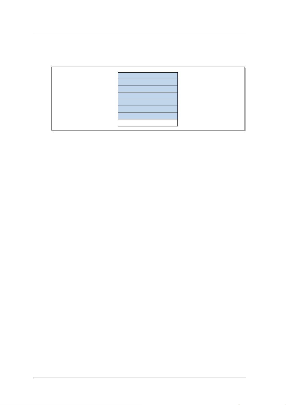
CHAPTER 3. SPI-2213 Architecture
Loader Implementation
Loader is implemented on the MMA-G and all lower board as shown below.
MRA-F #5
MRA-F #4
MRA-F #3
MRA-F #2
MRA-F #1
MRA-F #0
MMA-G
MEI-B
Figure 3.20 Loader Block
3.3.3.8 Universal Loading Management (ULM)
ULM downloads and executes the packages that are identified in the file list downloaded
by loader during pre-loading process. Also, ULM monitors the executed software and
provides the running software information, and supports the restart and the software upgrade
by the command. In addition, in the initialization stage, ULM sets the system time by using
the Time of Date information obtained from a GPS receiver and periodically performs the
synchronization with the NTP server by actuating as an NTP client after the loading is
completed.
ULM Main Functions
System initialization and reset
System reset by command
Act as internal RS & IS of lower board
Software management
Monitor the operation of software block and restart the software block in abnormal
state
Software restart by command
Provide information on software block and the status
Inventory Management
ULM provides the information such as the software version for the components,
the PBA ID, the PBA version and the serial number, etc.
Function of reporting the inventory information when performing the initialization,
adding and extending the components
Online upgrade and version management for the software
ULM provides the functions of updating the software and the firmware, upgrading the
package and managing the version.
3-28
© SAMSUNG Electronics Co., Ltd.

Mobile WiMAX RAS SPI-2213 System Description/Ed.00
System time information synchronization
Synchronize system time information with NTP server as a NTP client and transmit
the time information to the lower boards
Time Zone setup
Setup Time Zone and Daylight Saving Time (DST)
Mortem time update
Setup mortem time after system time information synchronization
ULM Implementation
ULM is implemented on the MMA-G and all lower board as shown below.
MRA-F #5
MRA-F #4
MRA-F #3
MRA-F #2
MRA-F #1
MRA-F #0
MMA-G
MEI-B
Figure 3.21 ULM Block
© SAMSUNG Electronics Co., Ltd. 3-29

CHAPTER 3. SPI-2213 Architecture
3.3.3.9 Common Performance Management (OPM)
OPM collects and provides the performance data for the upper management system operator
to know the SPI-2213 performance. The OPM collects the event generated during the
system operation and the performance data and transmits them to the management system.
The collection cycle of the statistics data of the actual OPM can be set as 15 minutes,
30 minutes, 60 minutes, and if the entire statistics file of the binary format is created every
15 minutes, the management system collects it periodically via the FTP/SFTP.
OPM Main Functions
Record and collect statistics data
Record statistics data to the memory and generate the statistics file by regularly
collecting data per each board
Save the statistics data
Save the statistics data of each board in its own nonvolatile storage during up to eight
hours
Inquire and change the statistics configuration information
Inquire and change the collection cycle (BI) and the threshold of the statistics data
Threshold Cross Alert (TCA)
Generate the TCA (Critical, Major, Minor) according to the defined threshold in every
collection cycle and report it to the UFM
Monitor the statistics in real time
Provide the real-time monitoring function for the specific statistics item designated by
the operator
OPM Implementation
OPM is implemented on the MMA-G and all lower board as shown below.
MRA-F #5
MRA-F #4
MRA-F #3
MRA-F #2
MRA-F #1
MRA-F #0
MMA-G
MEI-B
3-30
Figure 3.22 OPM Block
© SAMSUNG Electronics Co., Ltd.

Mobile WiMAX RAS SPI-2213 System Description/Ed.00
3.3.3.10 Common Subscription Service Management (OSSM)
OSSM distributes the PLD data necessary for the software blocks, and reports the data
changed to the corresponding software block if PLD data are changed. Also, it supports the
function to maintain the consistency of PLD data that are scattered in the system.
OSSM Major Functions
PLD distribution
OSSM loads PLD to the shared memory for software block in order to access PLD
PLD change report
Report the changes of PLD to the corresponding software block
PLD audit
Maintain the consistency of PLDs which are distributed in the SPI-2213 (between
main board and lower boards)
OSSM Implementation
OSSM is implemented on the MMA-G and all lower board.
MRA-F #5
MRA-F #4
MRA-F #3
MRA-F #2
MRA-F #1
MRA-F #0
MMA-G
MEI-B
Figure 3.23 OSSM Block
© SAMSUNG Electronics Co., Ltd. 3-31

CHAPTER 3. SPI-2213 Architecture
3.3.3.11 Common Event Router (OER)/Common Event Viewer (OEV)
The OER/OEV manages the event history as the text format. The OER/OEV transmits the
information on all the events received from the OAM applications to the related agent
(OAGS, WebEMT), and creates and saves the history file of the daily/hourly events, and
displays the log contents on the operator window (IMISH) in real time.
OER Major Functions
Event transmission
OER/OEV transmits the information on the generated event to the OAGS or the
WebEMT block, thus it enables to report it to the management system.
Creating and saving the event history file
OER/OEV creates and saves the daily/hourly event history file in its own nonvolatile
storage as the 1 Mbyte maximum size.
Event display
OER/OEV displays the event generated in the SPI-2213 on the operator window
(IMISH) in real time.
OER/OEV Implementation
OER/OEV is implemented on the MMA-G as shown in the figure below.
MRA-F #5
MRA-F #4
MRA-F #3
MRA-F #2
MRA-F #1
MRA-F #0
MMA-G
MEI-B
Figure 3.24 OER/OEV Block
3-32
© SAMSUNG Electronics Co., Ltd.

Mobile WiMAX RAS SPI-2213 System Description/Ed.00
3.3.3.12 Common Configuration Management (OCM)
OCM manages the SPI-2213 configuration and parameter with PLD, and it provides the
data that are necessary for the software blocks. Other software blocks can approach PLD
by the internal subscription service (OSSM), and through the command from EMI.
OCM provides the following functions: SPI-2213 configuration grow/degrow, inquiry and
change of configuration data and operational parameters.
OCM Major Functions
ACR configuration management
Manage the SPI-2213 system configuration with PLD
PLD inquiry and change
Upper management system inquires and changes PLD by command
PLD changes are updated in its own nonvolatile storage by operator’s command.
PLD audit
For the consistent PLD data with the upper management system
Grow/degrow of resources
Link, board, sector, the auxiliary devices in the SPI-2213
OCM Implementation
OCM is implemented on the MMA-G. as shown in the figure below.
MRA-F #5
MRA-F #4
MRA-F #3
MRA-F #2
MRA-F #1
MRA-F #0
MMA-G
MEI-B
Figure 3.25 OCM Block
© SAMSUNG Electronics Co., Ltd. 3-33

CHAPTER 3. SPI-2213 Architecture
3.3.3.13 RAS Diagnosis Management (RDM)
The RDM checks if internal and external connection paths or resources of the SPI-2213 are
normal. The connection paths are roughly divided into the external path between t he SPI- 2213
internal IPC path and another NE and the path between ACR and the SPI-2213.
In addition, it supports the on-demand test at the request of an operator and the periodical
test according to the schedule defined by the operator.
RDM Functions
Path T est
Internal path test: Ping test for the IPC path of the board level in NE
External path test: Traceroute test for external hosts
Traffic path test: Test for the UDP message-based bearer path between ACR and
the SPI-2213
Backhaul quality test: Test for the loss, delay and delay variance of backhaul
between ACR and RAS (based on ping)
Software Block Test
Ping test for main programs by processors
RF Exchange Test
Tx path, Receive Signal Strength Indicator-based (RSSI-based) Rx path and VSWR
diagnosis
DU-RRH Loopback Test
Support of loopback function for ‘Digital I/Q and C & M’ interface
Backhaul performance monitoring test
Quality (packet loss, delay and delay variance) measurement for backhaul between
ACR and the SPI-2213
Periodical online test by the operator setting
Change of the Diagnosis Schedule
Schedule setup, such as diagnosis period, start time and end time of periodical online test
Support of Call Trace Function
It reports the call trace information (signaling message of a specific MS, RF parameter,
and traffic statistics) to the management system via SNMPD.
Virtual Interface (VIF) generation and removal
Generate and remove VIF based on physical link configuration in PLD
VIF state management
Change the state of physical VIF with link failure
RF Module Setup and Control
Transmission of the setup information required for the RF module, redundancy
structure and management of failure/status
3-34
© SAMSUNG Electronics Co., Ltd.

Mobile WiMAX RAS SPI-2213 System Description/Ed.00
RDM Configuration
The RDM is implemented on the MMA-G as shown in the figure below.
MRA-F #5
MRA-F #4
MRA-F #3
MRA-F #2
MRA-F #1
MRA-F #0
MMA-G
MEI-B
Figure 3.26 RDM Block
© SAMSUNG Electronics Co., Ltd. 3-35

CHAPTER 3. SPI-2213 Architecture
This page is intentionally left blank.
3-36
© SAMSUNG Electronics Co., Ltd.

Mobile WiMAX RAS SPI-2213 System Description
CHAPTER 4. Message Flow
4.1 Call Processing Message Flow
4.1.1 Initial Access
The following is the procedure to set the Provisioned Service Flow (SF) of the networkinitiated Dynamic Service Add (DSA) mode in the process of the initial network entry.
An MS periodically receives Downlink Channel Descriptor (DCD), Downlink-MAP (DLMAP), Uplink Channel Descriptor (UCD) and Uplink-MAP (UL-MAP) messages from the
RAS in the initial access, acquires the downlink channel synchronization and the uplink
parameter and sets the Provisioned SF connection. The NWG standard defines PMIP and
CMIP to support Mobile IP and the procedure below takes account of both PMIP and CMIP.
But, ACR supports PMIP only.
© SAMSUNG Electronics Co., Ltd. 4-1

CHAPTER 4. Message Flow
MS RAS ACR AAA
1) RNG-REQ
2) RNG-RSP
3) SBC-REQ
HA
4) MS_PreAttachment_Req
6) SBC-RSP
9) REG-REQ
12) REG-RSP
15) DSA-REQ
16) DSA-RSP
19) DSA-ACK
In PMIP case
In CMIPcase
5) MS_PreAttachment_Rsp
7) MS_PreAttachment_Ack
8) Authentication & Key Exchange
10) MS_Attachment_Req
11) MS_Attachment_Rsp
13) MS_Attachment_Ack
14) Path Registration Request
17) Path Registration Response
18) Path Registration Ack
20) DHCP Discover
21) MIP REG REQ
22) MIP REG RSP
23) DHCP Offer
24) DHCP Request
25) DHCP Ack
26) Agent Advertisement
27) MIP REG REQ
28) MIP REG REQ
29) MIP REG RSP
30) MIP REG RSP
4-2
31) ACR
32) ACA
Figure 4.1 Initial Access Process
© SAMSUNG Electronics Co., Ltd.

Mobile WiMAX RAS SPI-2213 System Description/Ed.00
Classification Description
(1)~(2) The MS transmits the RNG-REQ message including its own MAC address and the
Ranging Purpose Indication to the RAS, and the RAS allocates the Basic & Primary
Management CID and transmits the RNG-RSP message to the MS.
(3)~(4) The MS transmits the SBC-REQ message to the RAS including the physical
parameter and the authorization policy information which it supports.
The RAS transmits the MS_PreAttachment_Req message to the ACR including the
authorization policy support via the Default IP address and the UDP port number of
the ACR.
(5)~(7) The ACR transmits the MS_PreAttachment_Rsp message to the RAS including the
supported authorization policy, and the RAS extracts the information received from the
ACR, attaches it to the SBC-RSP message and transmits it to the MS.
Then, RAS transmits the MS_PreAttachment_Ack to the ACR, and notifies the start
point of the next process (EAP transmission) explicitly.
(8) The procedure of the subscriber authentication between the MS and the AAA server
is performed, and when the authentication is successful, the ACR receives the
provisioned policy information for each subscriber from the AAA server.
For the detailed information, see ‘4.1.2 Authentication’.
(9)~(13) The MS transmits the REG-REQ message to the RAS including the registration
information (MS Capabilities, CS Capabilities, HO Support, etc), and the RAS
transmits the MS_Attachment_Req message to the ACR to inquire the corresponding
MS Capability and the corresponding CS Capability. The ACR transmits the response
to the RAS including the result of the requested registration information, and the RAS
transmits the REG-RSP message to the MS. The RAS transmits the
MS_Attachment_Ack to the ACR, and notifies the start point of the next process
explicitly.
(14)~(19) To request the DSA for the Pre-Provisioned SF, the ACR transmits the RR-Request
message to the RAS, including the SFID, the Resource Description field (SF/CS
parameter) and the Data Path ID (=GRE Key) field to set the data path with the RAS.
The RAS receives this message and performs admission control for this, and then
transmits the DSA-REQ message to the MS. The MS attaches the Confirmation Code
to the DSA-RSP message as a result of DSA-REQ and transmits the message to the
RAS, and the RAS transmits the RR-Response message to the ACR including the
Data Path ID to set the data path with the ACR. Then the ACR transmits the RR-
Confirm message to the RAS, and the RAS transmits the DSA-ACK message to the
MS.
(20)~(25) This is the procedure to allocate the IP address to the MS, which uses the PMIP, if the
MS requests the DHCP procedure to acquire the IP address, the ACR performs the
PMIP procedure.
(26)~(30) This is the procedure to allocate the IP address to the MS, which uses the CMIP, if the
MS requests the MIP registration directly, the ACR operates as the FA and interworks
with the HA and allocates the MIP address to the MS.
(31)~(32) The start of accounting process for the service flow created in the stages of (14) to
(19) is notified to the AAA server.
© SAMSUNG Electronics Co., Ltd. 4-3

CHAPTER 4. Message Flow
4.1.2 Authentication
At the Time of Initial Access
The MS authentication procedure performed in ‘4.1.1 Initial Access’ is as follows:
MS RAS ACR
0) MS_PreAttachment_Ack
2) PKM-RSP
(PKMv2 EAP-Transfer)
3) PKM-REQ
(PKMv2 EAP-Transfer)
Repeat
8) PKM-RSP
(PKMv2 EAP-Transfer)
9) PKM-REQ
(PKMv2 EAP-Transfer)
14) PKM-RSP
(PKMv2 EAP-Transfer)
17) PKM-RSP
(PKMv2 SA-TEK-Challenge)
18) PKM-REQ
(PKMv2 SA-TEK-Request)
19) PKM-RSP
(PKMv2 SA-TEK-Response)
20) PKM-REQ
(PKMv2 Key Request)
21) PKM-RSP
(PKMv2 Key Reply)
1) AuthRelay-EAP-Transfer
4) AuthRelay-EAP-Transfer
7) AuthRelay-EAP-Transfer
10) AuthRelay-EAP-Transfer
13) AuthRelay-EAP-Transfer
15) Key_Change_Directive
16) Key_Change_Directive_Ack
5) DER
DEA
6)
11) DER
12) DEA
AAA
Figure 4.2 Authentication Procedure (At the time of initial access)
Classification Description
(0)~(2) When the ACR receives MS_PreAttachment_Req_Ack for SBC-RSP from the RAS,
the ACR includes the EAP Request/Identity payload in the AuthRelay-EAP-Transfer
message and transmits the message to the RAS to start the EAP authentication. The
RAS relays the received EAP payload to the MS by using the PKMv2 EAP-
Transfer/PKM-RSP message.
(3)~(5) The MS transmits the PKMv2 EAP-Transfer/PKM-REQ message to the RAS by
including the NAI in the EAP Response/Identity, and the RAS relays this to the ACR
by using the AuthRelay-EAP-Transfer message. Then, the authenticator of the ACR
analyzes the NAI and transmits the Diameter EAP Request (DER) message to the
home AAA of the MS.
(6)~(11) The subscriber authentication procedure is performed between the MS and the AAA
server according to the EAP-method.
4-4
© SAMSUNG Electronics Co., Ltd.

Mobile WiMAX RAS SPI-2213 System Description/Ed.00
(Continued)
Classification Description
(12)~(16) When the EAP authentication is completed successfully, the ACR receives the
Master Session Key (MSK) which is the prior key to provide the security and the
Provisioned Policy on each subscriber via the DEA message from the AAA server.
The ACR creates the AK from the MSK, and transmits the Key_Change_Directive
message including the created AK Context information and the Security Association
(SA) information of the MS to the RAS. In addition, the RAS relays EAP Success to
the MS by using PKMv2-EAP-Transfer.
(17)~(19) After the EAP authentication, the RAS verifies the AK key value which it has with MS,
and transmits the SA-TEK-Challenge message to the MS to notify the start of the SA
negotiation, and the MS verifies the CMAC of the SA-TEK-Challenge message,
checks the AK key value, and transmits the SA negotiation information to the RAS by
using SA-TEK-Request. The RAS transmits SA-TEK-Response including the AKID
and the SA Descriptor which is the final result of the SA negotiation to the MS.
(20)~(21) The MS requests the Traffic Encryption Key (TEK) to the RAS by using PKMv2 Key-
Request, and the RAS creates the TEK randomly and transmits it to the MS by using
the PKMv2 Key-Reply message. Then, the TEK is transmitted by being encrypted via
the Key Encryption Key (KEK).
Keys and Functions
The functions of the keys are as follows.
- MSK: creates the AK
- AK: creates the CMAC key
- KEK: encrypts the TEK
- CMAC key: provides integrity for the MAC management message
- TEK: encrypts traffics in wireless sections
© SAMSUNG Electronics Co., Ltd. 4-5

CHAPTER 4. Message Flow
At the Time of Authenticator Relocation
When the MS performs the CSN-anchored Handover (HO), or the Idle Mode MS moves to
another ACR area and performs the location update, the following re-authentication
procedure is performed to move the authenticator from the existing Serving ACR to the
T ar ge t ACR. The Target ACR triggers i n order that t he MS perform s the EAP authentication
procedure with the AAA server again, and then, when the result of the authentication result
is notified to the Serving ACR, the Authenticator Relocation procedure is completed.
MS T-RAS
4) PKMv2-RSP
T-ACR S-ACR
1) Relocation Notify
2) Relocation Notify Ack
3) AuthRelay EAP Transfer
5) Serving ASN triggers MS re-authentication with AAA Server
AAA
8) PKMv2-RSP
11) SA-TEK handshake
7) AuthRelay EAP Transfer
9) Key Change Directive
10) Key Change Directive Ack
12) Key Change Confirm
13) Key Change Confirm Ack
14) Relocation Complete_Req
15) Relocation Complete_Rsp
16) Relocation_Complete_Ack
17) Context_Rpt
18) Context_Ack
6) DEA
Figure 4.3 Authentication Procedure (At the time of the Authenticator Relocation)
Classification Description
(1)~(2) The new authenticator, T-ACR, exchanges the Relocation Notify/Ack message with
the previous authenticator, S-ACR, to perform re-authentication and authenticator
relocation.
4-6
(3)~(11) The new authenticator, T-ACR, exchanges the Relocation Notify/Ack message with
the previous authenticator, S-ACR, to perform re-authentication and authenticator
relocation.
(12)~(13) The RAS sends the Key Change Confirm message to the authenticator (T-ACR) to
notify it that re-authentication is complete with the MS.
(14)~(16) The T-ACR completes the authenticator relocation procedure by exchanging the
Relocation Confirm/Ack message with the S-ACR.
(17)~(18) After the authenticator relocation, the new authenticator notifies the anchor that the
authenticator has been changed through the context Rpt procedure.
© SAMSUNG Electronics Co., Ltd.

Mobile WiMAX RAS SPI-2213 System Description/Ed.00
4.1.3 Status Change
Awake Mode Idle Mode
If the data traffic is not transmitted/received for a certain time, the status of MS is changed
from the Awake Mode to the Idle Mode.
Sleep Mode Idle Mode Change
The MS of the Sleep Mode is not changed into the Idle Mode, immediately.
Before being changed from the Sleep Mode into the Idle Mode, the MS is changed
to the Awake Mode, first, and then, after requesting DREG, it is changed into the
Idle Mode.
The deregistration procedure to be changed into the Idle Mode is divided into the MSinitiated Idle Mode change and the Network-initiated Idle Mode change, and the following
indicates the procedure of the MS-initiated Idle Mode change.
MS RAS ACR
1) DREG-REQ
(Code=0x01, Paging Cycle Request)
4) DREG-CMD
(ActionCode, Paging Controller ID,
Paging Information)
2) IM_Entry_State_Change_Req
3) IM_Entry_State_Change_Rsp
5) IM_Entry_State_Change_Ack
6) Path_Dereg_Req
7) Path_Dereg_Rsp
8) Path_Dereg_Ack
9) ACR
10) ACA
AAA
Figure 4.4 Awake Mode Idle Mode Status Change Procedure
Classification Description
(1) When the MS is changed into the Idle Mode, it creates the DREG-REQ message and
transmits it to the RAS, and the value of the De-Registration Request Code field is set
as 0 x 01.
(2)~(5) The RAS creates the IM_Entry_State_Change_Req message including the context
information of the MS and transmits it to the ACR (Paging Controller), and the ACR
creates the IM_Entry_State_Change_Rsp message including the Action Code (0 x
05), the paging information (PAGING_CYCLE, PAGING_OFFSET) and the Idle Mode
Retain Flag and transmits the message to the RAS. The RAS transmits the DREG-
CMD including the received information to the MS.
© SAMSUNG Electronics Co., Ltd. 4-7

CHAPTER 4. Message Flow
Classification Description
(6)~(8) If the Network re-entry from the MS is not transmitted until the Idle Resource Retain
(9)~(10) As the MS status is changed to Idle Mode, the RAS notifies the charging termination
Awake Mode Sleep Mode
The Awake Mode and the Sleep Mode of the MS can be classified only by the RAS, and
the ACR does not classify the two kinds of status, and recognizes and manages both of
them as the Awake Mode.
(Continued)
timer expires, the RAS performs the Data Path (DP) Release procedure with the
ACR.
message to the AAA server and updates the charging information in the AAA server.
MS RAS ACR
Awake
1) MOB_SLP-REQ
2) MOB_SLP-RSP
Sleep
DL Traffic
3) MOB_TRF-IND
4) BW Request Header
Awake
Figure 4.5 Awake Mode Sleep Mode Status Change Procedure
Classification Description
(1)~(2) If the MS does not transmit/receive the data for a certain time (set by the MS/RAS as
the parameter), timeout is generated in its own timer, and thus the mode is changed
from the Awake Mode to the Sleep Mode. Then, the MS transmits the MOB_SLP-
REQ message to the RAS, and the RAS transmits the MOB_SLP-RSP message for
this, and the status of MS is changed into the Sleep Mode.
(3)~(4) If the terminating traffic exists in the Sleep Mode MS, the RAS transmits the
MOB_TRF-IND message in the listening period of the corresponding MS, and the
MS which receives this, sets the BW value as 0 in the UL BW Request and transmits
it to the RAS. The RAS receives this message and recognizes that the status of MS
has been changed into the Awake Mode, and transmits the traffic to the MS.
4-8
© SAMSUNG Electronics Co., Ltd.
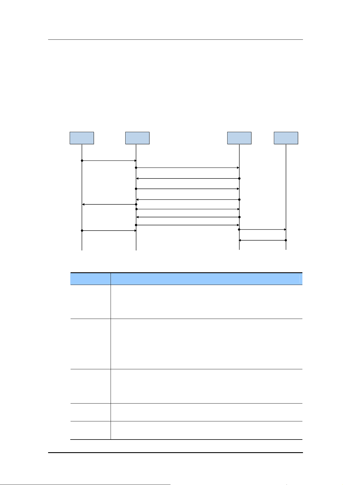
Mobile WiMAX RAS SPI-2213 System Description/Ed.00
Idle Mode Awake Mode (QCS)
When an MS in Idle Mode responds for the paging because of incoming traffic or sends the
traffic, the status of MS is changed from the Idle Mode into Awake Mode. In both cases,
the MS should perform the network re-entry procedure to change the status into the Awake
Mode and the Mobile WiMAX system of Samsung basically takes account of the QCS
procedure as the network re-entry method.
The following is the case where the mode is changed from the Idle Mode to the Awake
Mode at the time of the network re-entry (QCS).
MS RAS ACR
1) RNG-REQ
(PC ID, Ranging Purpose=0)
6) RNG-RSP
(CID Update)
10) BW Request Header
2) IM Exit State Change Request
3) IM Exit State Change Response
4) Path Reg Request
5) Path Reg Response
7) CMAC_Key_Count_Update
8) CMAC_Key_Count_Update_Ack
9) Path Reg Ack
11) ACR
12) ACA
AAA
Figure 4.6 Idle Mode Awake Mode (QCS) Procedure
Classification Description
(1) If the Idle Mode MS is changed into the Awake Mode, the MS creates the RNG-REQ
message including the MAC address and the Paging Controller ID value and
transmits the message to the RAS. Then, the value of the Ranging Purpose
Indication field is set as 0 x 00 (=Network Re-entry).
(2)~(3) The RAS creates the IM Exit State Change Request message including the
parameter of the received RNG-REQ message and transmits the message to the
ACR. The ACR checks the status information of the Idle Mode of the MS, creates the
IM Exit State Change Response message including the Idle Mode Retain information
to perform the QCS procedure and the AK Context information for the CMAC
authentication and transmits the message to the RAS.
(4)~(5) The RAS transmits the Path Registration Request message including the data path
(UL) information such as the GRE Key to the ACR to set the data path with the ACR.
The ACR responds to the RAS as the Path Registration Response message
including the data path (DL) information such as the GRE Key for this.
(6) The RAS replies with the RNG-RSP message along with HO Optimization Flag for
the QCS and relevant CID_Update and SA-TEK_Update information.
(7)~(8) The RAS notifies the new CMAC_KEY_COUNT value updated by the MS to the
ACR, which is an authenticator.
© SAMSUNG Electronics Co., Ltd. 4-9

CHAPTER 4. Message Flow
Classification Description
(9) The ACR receives the Path Registration Ack message and is notified of data path set
results.
(10) If an MS receives RNG-RSP, the MS transmits BW Request Header to notify the
system that the status is changed into the Awake Mode.
(11)~(12) As the mode is changed into the Awake Mode and new CID (Transport CID) is
assigned, new charging start message is notified to update the charging information
of the AAA server.
Changing from Idle Mode to Awake Mode
For the procedure that the MS status is changed from Idle Mode to Awake Mode
due to paging, refer to ‘4.1.5’.
4.1.4 Location Update
(Continued)
Inter-RAS Location Update
The following is the location update procedure when the MS moves to other paging group
in the same ACR.
MS
1) MOB-PAG_ADV
1) MOB-PAG_ADV
2) RNG-REG
(Location Update Request, Paging Controller ID)
5) RNG-RSP
(Location Update Response)
RAS 1
(PG 1)
Figure 4.7 Inter-RAS Location Update Procedure
RAS 2
(PG 2)
ACR
3) LU Request
4) LU Response
6) CMAC_Key_Count_Update
7) CMAC_Key_Count_Update
8) LU Confirm Ack
Classification Description
4-10
(1) When the Idle Mode MS in the paging group 1 moves to the paging group 2, it
receives the PAG-ADV message and recognizes that the location has been
changed.
(2)~(3) The MS transmits the RNG-REQ message to a new RAS (RAS 2) including the MAC
address, the Location Update Request, and the Paging Controller ID and the RAS 2
transmits the Location Update Request message to the ACR.
© SAMSUNG Electronics Co., Ltd.

Mobile WiMAX RAS SPI-2213 System Description/Ed.00
(Continued)
Classification Description
(4)~(5) The ACR transmits the Location Update Response message including the paging
information and the AK Context information to the RAS 2.
The RAS 2 checks the CMAC validation and transmits the RNG-RSP message
including the LU Response to the MS.
(6)~(7) The RAS notifies the new CMAC_KEY_COUNT value updated by MS to the ACR,
which is an authenticator.
(8) The ACR transmits the LU Confirm message and notifies that the location update
procedure is completed.
© SAMSUNG Electronics Co., Ltd. 4-11

CHAPTER 4. Message Flow
Inter-ACR Location Update (Anchor Relocation)
The following figure indicates the inter-ACR location update procedure when the MS
moves to other ACR area.
MS T-RAS
T-ACR
S-ACR AAA HA
1) RNG-REQ
6) RNG-RSP
7) CMAC_Key_Count_Update
10) CMAC_Key_Count_update_Ack
18) MOB_PAG-ADV
(0b10 Enter Net.) (Event Code 0x01)
19) RNG-REQ
28) RNG-RSP
29) CMAC_Key_Count_Update
32) CMAC_Key_Count_Update_Ack
2) LU Request
5) LU Response
11) LU Confirm
17) MS Paging Announce
20) Exit MS State Change Request
23) IM Exit State
Change Response
24) Path Reg Request
27) Path Reg Response
33) Path Reg Ack
3) LU Request
4) LU Response
8) CMAC_Key_Count_Update
9) CMAC_Key_Count_update_Ack
12) PC_relocation_Ind
13) PC_relocation_Ack
14) LU Confirm
15) Relocation Notify
16) Relocation Notify Ack
21) IM Exit State Change Req
22) IM Exit State Change Rsp
25) Path Reg Request
26) Path Reg Response
30) CMAC_Key_Count_Update
31) CMAC_Key_Count_Update_Ack
34) Path Reg Ack
35) Re-authentication
36) Context Report (to DPF)
37) Context Ack
4-12
38) Anchor DPF HO Trigger
39) Anchor DPF HO Request
In PMIP case
40) MIP REG REQ
41) MIP REG RSP
In CMIP case
42) Agent Advertisement
43) MIP REG REQ
46) CMIP REG RSP
47) Anchor DPF HO Response
44) MIP REG REQ
45) MIP REG RSP
48) ACR/AAA/HA Resource release action
Figure 4.8 Inter-ACR Location Update Procedure
© SAMSUNG Electronics Co., Ltd.

Mobile WiMAX RAS SPI-2213 System Description/Ed.00
Classification Description
(1)~(2) If the paging group is changed, the MS transmits the RNG-REQ message including
the MAC address, the Location Update Request and the Paging Controller ID to a new
T-RAS (Target RAS). The T-RAS transmits the Location Update Request message
including the Paging Controller ID to its own default ACR.
(3)~(5) When the received Paging Controller ID does not belong to the Target ACR
(T-ACR), the T-ACR transmits the Location Update Request message of which the
APC Relocation Destination is set as its own Paging Controller ID to the previous
Serving ACR (S-ACR) via the R4 interface to change the Paging Controller. The S-
ACR responds by using the Location Update Response message including the
information on whether to allow the Paging Controller Relocation and the Context
information of the corresponding MS.
(6) When the T-RAS receives the Location Update Response message, it sets as ‘LU
Response=Success’, transmits the RNG-RSP message to the MS, and checks if the
paging controller is changed into the T-ACR by transmitting the LU Confirm message.
(7)~(10) The T-RAS notifies the new CMAC_KEY_COUNT value updated by the MS to the S-
ACR, which is an authenticator.
(11) The LU Confirm message is sent to confirm that the T-ACR is now the paging
controller.
(12)~(14) The T-ACR, after Location Update Confirm, notifies the FA and the Authenticator which
are still located in the S-ACR of that the Paging Controller has been changed.
(15) The T-ACR requests the FA Relocation for the MS to the S-ACR.
(16)~(18) The S-ACR which receives the request of the FA/DPF Relocation from the T-ACR
allows the relocation in the T-ACR, then, the T-ACR/RAS requests paging to the
corresponding MS to trigger the relocation.
(19)~(34) The MS which receives the MOB_PAG-ADV message performs the QCS which is the
Network Re-Entry procedure with the network.
(35)~(37) This is the procedure to relocate the Authenticator from the S-ACR to the T-ACR, the
T-ACR triggers in order that the MS performs the EAP authentication procedure with
the AAA server, and notifies the S-ACR of the authentication result, then completes
the Authenticator Relocation procedure.
(38)~(39)
(40)~(41) If the MS uses the PMIP, the T-ACR instead of the MS registers the MIP to the HA.
(42)~(46) If the MS uses the CMIP, the ACR operates only as the FA, and the MS registers the
(47)~(48) When the anchor DPF relocation is completed successfully, S-ACR releases the
The T-ACR requests the Anchor DPF Relocation for the MS to the S-ACR.
MIP in the HA directly.
existing connection with AAA and HA.
Inter-ASN Location Update
The inter-ASN location update procedure is the same with the inter-ACR location update
procedure.
© SAMSUNG Electronics Co., Ltd. 4-13

CHAPTER 4. Message Flow
4.1.5 Paging
Paging can be classified into the following two types.
The RAS broadcasts the MOB_PAG-ADV message periodically and notifies the MS
of the corresponding paging group. The MS is changed into the Idle Mode and checks
if the paging group of the MS is changed by checking the MOB_PAG-ADV message
periodically based on the paging information (Paging Cycle, Paging Offset, PGID)
received from the system.
If the traffic to be transmitted to the Idle Mode MS exists in the ACR, the ACR
triggers the MOB_PAG-ADV message to the RAS to change the corresponding MS
into the Awake Mode.
The following figure is the procedure to perform paging on the Idle Mode MS.
MS RAS ACR
1) MS Paging Announcement
2) MOB PAG-ADV
QCS
Figure 4.9 Paging Procedure
Incoming traffic
Classification Description
(1)~(2) When receiving the packet to be transmitted to the specific MS, the ACR transmits the
MS Paging Announce message including the MAC address, the Paging Group ID and
the Action Code (0x10) of the MS when the corresponding MS is the Idle Mode to the
RAS. The RAS transmits the MOB_PAG-ADV message including the information
received from the ACR to the MS.
After this, the MS performs the QCS procedure with the network. For the information on
the QCS procedure, see the procedure of ‘Idle Mode Awake Mode’ in ‘4.1.3’.
4-14
© SAMSUNG Electronics Co., Ltd.

Mobile WiMAX RAS SPI-2213 System Description/Ed.00
4.1.6 Handover
Inter-RAS Handover
The following is the inter-RAS handover procedure.
MS S-RAS T-RAS1 T-RAS2ACR
1) MOB-MSHO-REQ
2) HO-Request
3) HO-Request
6) MOB-BSHO-RSP
9) MOB-HO-IND
5) HO-Response
7) HO-Ack
10) HO-Confirm
15) HO-Ack
19) Path Reg Request (For Data Integrity)
20) Path Reg Response
21) Path Reg Ack
27) Path De-Reg Request
(For Data Integrity)
30) Path De-Reg Response
16) Path Pre-Reg Request
17) Path Pre-Reg Response
22) Fast Ranging IE ()
23) RNG-REQ
25) Path Reg Response
26) RNG-RSP
28) Path De-Reg Request
29) Path De-Reg Response
4) HO-Response
8) HO-Ack
11) HO-Confirm
12) Context-Request
13) Context-Report
14) HO-Ack
18) Path Pre-Reg Ack
24) Path Reg Request
31) MAC PDU with SN Report Header (Opt.) or BW Request with 0 (Opt.)
33) HO-Complete
35) CMAC_KEY_COUNT Update Ack
36) Path De-Reg Request
37) Path De-Reg Response
38) Path De-Reg Ack
32) HO-Complete
34) CMAC_KEY_COUNT Update
Figure 4.10 Inter-RAS Handover Procedure
© SAMSUNG Electronics Co., Ltd. 4-15

CHAPTER 4. Message Flow
Classification Description
(1)~(3) The MS transmits the MOB_MSHO-REQ message including the Neighbor BS
(4)~(8) The T-RAS transmits the HO-Response message including its own capability
(9)~(11) The MS transmits the MOB_HO-IND message including the HO-IND Type and the
(12)~(15) The T-RAS transmits the Context-Request message to the ACR (Authenticator) to
(16)~(21) The path pre-registration is executed to set a new data path between the ACR and the
(22) If T-RAS allows the request of an MS, the T-RAS notifies UL_MAP IE to enable the
(23) The MS transmits to the T-RAS the RNG-REQ message that contains the MAC
(24)~(25) The path registration procedure is executed to exchange the SF information that is
(26) The T-RAS replies with the RNG-RSP message along with HO Optimization Flag,
(27)~(30) If the S-RAS transmits all the traffic to the T-RAS, the forwarding path is removed.
(31) If an MS successfully receives the RNG-RAS message, the MS transmits Bandwidth
(32)~(33) The T-RAS transmits the HO-Complete message to S-RAS to notify the completion of
(34)~(35) The RAS notifies the new CMAC_KEY_COUNT value updated by MS to the ACR,
(36)~(38) When the handover procedure is completed, the old path between the S-RAS and the
Inter-ACR Handover
Inter-ACR handover within the same ASN considers the path extension via the R6 interface.
The inter-ACR handover procedure is the same with the inter-RAS handover procedure,
but data forwarding between the serving RAS and the target RAS is not supported.
(RAS) ID and the parameter related to handover to the current Serving RAS
(S-RAS) to request handover. The S-RAS transmits the HO-Request message
including the received MOB_MSHO-REQ parameter and the context information to
the ACR, and the ACR forwards the HO-Request message to the Target RAS (T-RAS).
information to the ACR, and the S-RAS transmits the MOB_BSHO-RSP message
including the Recommended Neighbor BS-IDs, the HO-ID and the parameter result
value to the MS.
Target BS-ID to the S-RAS to notify handover finally, and the S-RAS transmits the HO-
Confirm message including the context information and the Data Integrity information
(e.g., Buffered SDU SN) of the MS to the T-RAS.
request the AK Context information, and the ACR responds by using the Context-
Response message including the AK context information.
T-RAS. In addition, a forwarding path is set to send to the T-RAS the traffics that the
S-RAS has not yet transmitted to the MS, and the traffics are sent to the T-RAS.
MS to transmit HO Ranging Request via uplink.
address, Serving BS-ID, HO indication, and HO-ID.
mapped with the data path created between the ACR and the T-RAS through the
steps (16)~(18).
CID_Update, and SA-TEK_Update.
Request (BR) MAC PDU to RAS to inform the reception of the message.
handover.
which is an authenticator.
ACR is removed.
4-16
© SAMSUNG Electronics Co., Ltd.

Mobile WiMAX RAS SPI-2213 System Description/Ed.00
Inter-ASN Handover: ASN-Anchored Mobility
Inter-ASN handover is divided into the ASN-anchored mobility method via the R4
interface and the CSN-anchored mobility method via the R3/R4 interface. The following
figure indicates the inter-ASN handover procedure of the ASN-anchored mobility method,
the Serving ACR (S-ACR) performs the anchor function.
MS S-RAS T-ACR T-RAS1 T-RAS2
1) MOB-MSHO-REQ
2) HO-Request
S-ACR
3) HO-Request
4) HO-Request
8) MOB-BSHO-RSP
12) MOB-HO-IND
AK Context Transfer
R4 Data Path Setup
6) HO-Response
7) HO-Response
9) HO-Ack
13) HO-Confirm 14) HO-Confirm
23) HO-Ack
10) HO-Ack
16) Fast Ranging IE ()
18) Context-Request
19) Context-Report
22) HO-Ack 21) HO-Ack
25) Path Pre-Reg Request
26) Path Pre-Reg Response
29) Path Pre-Reg Ack
30) RNG-REQ
32) Path Reg Request
33) Path Reg Response
5) HO-Response
11) HO-Ack
15) HO-Confirm
17) Context-Request
20) Context-Report
24) Path Pre-Reg Request
27) Path Pre-Reg Response
28) Path Pre-Reg Ack
31) Path Reg Request
34) Path Reg Response
36) Path Reg Ack
37) RNG-RSP
38) MAC PDU with SN Report Header (Opt.) or BW Request with 0 (Opt.)
41) HO-Complete
46) Path De-Reg Request
47) Path De-Reg Response
40) HO-Complete
43) CMAC_COUNT_
UPDATE
44) CMAC_COUNT_
UPDATE Ack
35) Path Reg Ack
39) HO-Complete
42) CMAC_COUNT_UPDATE
45) CMAC_COUNT_UPDATE Ack
Figure 4.11 Inter-ASN Handover (ASN-Anchored Mobility)
The HO signaling procedure is the same with the inter-RAS handover procedure, however
in the HO signaling procedure, the procedure of exchanging the HO signaling message via
the R4 interface is added between the S-ACR and the Target ACR (T-ACR).
© SAMSUNG Electronics Co., Ltd. 4-17

CHAPTER 4. Message Flow
A
Inter-ASN Handover: CSN-Anchored Mobility
The following is handover of the CSN-anchored mobility method among the types of interASN handover, the anchor function is relocated from the Serving ACR (S-ACR) to the
T arget ACR (T -ACR).
CSN-anchored mobility is composed of the process that Authenticator/DPF Anchor is
relocated to the target ACR after ASN-anchored mobility handover is performed.
For convenience, the case that T-ACR triggers the relocation is defined in pull mode and
the other case that S-ACR triggers is in push mode. Mobile WiMAX system of Samsung
supports both pull mode and push mode.
The CSN-anchored mobility method follows the MIP standard, and the NWG defines the
PMIP and the CMIP for the MIP method. The first part of the CSN-anchored handover
signaling process is the same as the procedure of ASN-anchored mobility handover and the
procedure after the ASN-anchored handover is as follows:
MS T-RAS
Pull
Model
T-ACR
Inter-ASN HHO
1) Relocation Notify
2) Relocation Notify Ack
CR
S-
(Anchor)
AAA
HA
PMIP Re-registration
CMIP Re-registration
10) Agent Advertisement
11) CMIP REG REQ
14) CMIP REG RSP
Push
Model
5) Re-authentication
3) Relocation Request
4) Relocation Response
6) Anchor DPF HO Trigger
7) Anchor DPF HO Request
8) MIP REG REQ
9) MIP REG RSP
12) MIP REG REQ
13) MIP REG RSP
15) Anchor DPF HO Response
Pull Mode
16) Registration Revocation Request
17) Registration Revocation Ack
18) ACR
19) ACA
20) STR
21) STA
Figure 4.12 Inter-ASN Handover (CSN-Anchored Mobility)
4-18
© SAMSUNG Electronics Co., Ltd.
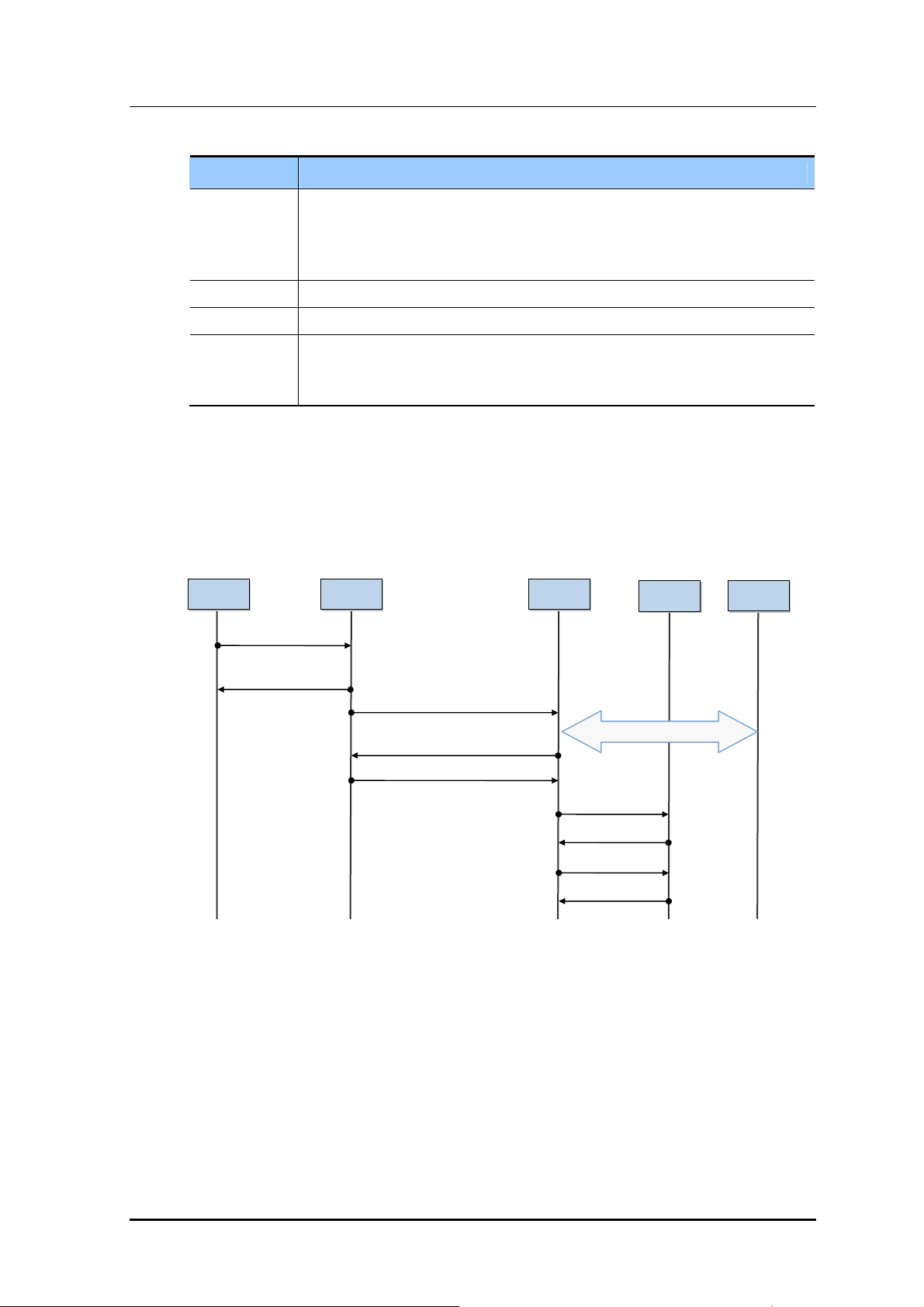
Mobile WiMAX RAS SPI-2213 System Description/Ed.00
(Req
)
(
)
Classification Description
(1)~(5) This is the procedure to relocate the Authenticator from the S-ACR to the T-ACR, the
T-ACR triggers in order that the MS performs the EAP authentication procedure with
the AAA server again. The T-ACR completes the Authenticator Relocation procedure
by notifying the S-RAS of the authentication result.
(6)~(15) FA relocation is triggered, and the registration of the PMIP or the CMIP is processed.
(16)~(17) The S-ACR cancels the S-ACR registration of the MS in the HA.
(18)~(21) The S-ACR updates the information on interworking with the AAA server and the final
accounting information of MS. Diameter is applied to AAA protocol, S-ACR performs
the session termination procedure.
4.1.7 Access Termination
Access Termination (Awake Mode)
The following is the procedure that the access is terminated because the power of the
Awake Mode MS is turned off.
MS RAS ACR
1) DREG-REQ
Code: 0
2) DREG-CMD
ActionCode: 4
3) Path Deregistration Request
(Power Down Indication)
5) Path Deregistration Response
6) Path Deregistration Ack
Figure 4.13 Access Termination (Awake Mode)
7) ACR
8) ACA
9) STR
10) STA
AAA
4) MIP release
HA
© SAMSUNG Electronics Co., Ltd. 4-19

CHAPTER 4. Message Flow
Classification Description
(1)~(3) If the power of the Awake Mode MS is turned off, the MS transmits the DREG-REQ
(4) ACR release the MIP related information with HA.
(5)~(6) The ACR notifies the RAS of the result of power down processing, and release the
(7)~(10) The S-ACR updates the information on interworking with the AAA server and the final
Access Termination (Idle Mode)
The following is the procedure that the access is terminated because the power of the Idle
Mode MS is turned off.
message including ‘Deregistration code=0’ to the RAS, and the RAS notifies the ACR
of this.
data path.
accounting information of MS. Diameter is applied to AAA protocol, S-ACR performs
the session termination procedure.
MS
1) RNG-REQ
(Location Update Request, Paging Controller ID)
4) RNG-RSP
(Location Update Response)
RAS ACR
2) LU Request
3) LU Response
5) LU Confirm
7) STR
8) STA
AAA
6) MIP release
Figure 4.14 Access Termination (Idle Mode)
Classification Description
(1)~(5) If the power of the Idle Mode MS is turned off, the MS transmits the RNG-REQ
message including the Power Down Indicator to the RAS, and the RAS notifies the
ACR of this. The ACR deletes the information of the MS.
(6) ACR release the MIP related information with HA.
(7)~(8) Diameter is applied to AAA protocol, S-ACR performs the session termination
procedure.
HA
4-20
© SAMSUNG Electronics Co., Ltd.

Mobile WiMAX RAS SPI-2213 System Description/Ed.00
4.2 Network Synchronization Message Flow
The SPI-2213 uses GPS for the system synchronization. The UCCM of the MMA-G, which
is the GPS reception module, creates the clock with the clock information received from a
GPS and then distributes the clock to each hardware module in the SPI-2213.
Clock information required by the RRH is sent from the MRA-F through ‘Digital I/Q and
C & M’, and the RRH recovers clock information from the signals to create necessary
clocks.
MMA-G(UCCM)
MBB-F
D
1Port
M
M
M
E
A
I
-
G
B
System Clock(56 MHz)
A
61.44 MHz
PP2S
40.96 S
80 msec
A
M
R
A
(0)
M
R
A
-
F
#
0
R
R
H
-
F
CCC
BBB
#
1
R
R
A
A
F
#
2
-
F
#
3
R
R
H
(1)
B
TDD signal
C
Digital I/Q and C & M
Analog 10 MHz
D
M
M
M
M
R
R
A
A
-
F
#
4
-
F
#
5
R
R
H
(2)
Figure 4.15 Network Synchronization Flow of SPI-2213
© SAMSUNG Electronics Co., Ltd. 4-21

CHAPTER 4. Message Flow
4.3 Alarm Signal Flow
The detection of failures in the SPI-2213 can be implemented by hardware interrupt or
software polling method. The failures generated in the SPI-2213 are reported to the
management system via the SNMP trap message.
Failure Alarm Types
System Failure Alarms
Time Sync Fail, Fan Fail, Temperature High, etc.
Board Failure Alarms
Hardware Failure Alarms: FUNCTION FAIL, BOARD DELETION, etc.
Software Failure Alarms: COMMUNICATION FAIL, PORT DOWN, CPU
OVERLOAD, etc.
RRH Failure Alarms
LOW GAIN, OVER POWER, VSWR FAIL, PLL UNLOCK, RRH INTERFACE
FAIL etc.
UDA
6 alarm input ports are supported for the rectifier alarm. Main AC Fail, Rectifier Fail,
Battery Fail, Cabinet Fan Fail, Heater Fail, Environment Alarm
Failure Report Message Flow
The main OAM (UFM) collects the failures detected from each board and UDA interface
of the SPI-2213 and notifies them to the management system. At this time, it only reports
the upper failure information by using the failure filtering function. If it receives the
command to inhibit the report for a specific failure or all system failures from the management
system, it does not report the failure report.
The flows for the failure detection and the report message are as shown in the figures below:
4-22
WSM
(SNMP Manage)
SPI-2213
MMA-G
MRA-F
#0~5
RRH-2
#0~2
Alarm detection
Alarm filtering
Alarm Report
(SNMP trap)
MEI-B
Figure 4.16 Alarm Signal Flow of SPI-2213
SPI-2213
MRA-F
RRH-2
#0~5
#0~2
Alarm detection
MMA-G
© SAMSUNG Electronics Co., Ltd.
Alarm detection
Alarm filtering
Alarm filtering
Alarm Report
Alarm Report
(SNMP trap)
(SNMP trap)
MEI-B

Mobile WiMAX RAS SPI-2213 System Description/Ed.00
MBB-F
F
A
N
-
F
D
48
MMA-G
A
B
M
M
M
R
E
I
UDA
-
B
(0)
(0)
D
M
R
R
A
F
R
R
H
A
-
-
F
(1)
(2)
M
A
-
F
(3)
R
R
H
(1)
M
R
R
A
A
F
F
(4)
M
R
A
-
-
F
(5)
C
R
R
H
(2)
Function Fail/DEL
A
Reset
B
Function Fail/DEL/Reset
C
Fan fail/High Temp.
D
Figure 4.17 Alarm and Control Structure of SPI-2213
© SAMSUNG Electronics Co., Ltd. 4-23

CHAPTER 4. Message Flow
4.4 Loading Message Flow
Loading is the procedure to download the software execution files and the data from the IS,
which are required to perform each function of each processor and each device of the SPI-
2213. Loading the SPI-2213 is performed in the procedure of initializing the system.
In addition, if a specific board is mounted on the system or the hardware is reset, or if the
operator of the upper management system reboots a specific board, loading is performed.
Loading is classified into two types, one is loading by using its own non-volatile storage
and the other is loading by using the remote IS. When the system is initialized for the first
time, the SPI-2213 receives the loading by using the remote IS, and after this, saves the
corresponding information in the internal storage, and backs up the recent information
periodically, and then it is available to avoid unnecessary loading. After the first
initialization, if the information saved in its own storage is the recent information by
comparing the version, the SPI-2213 does not receive the remote loading.
The loaded information includes the software image which is configured with the execution
file and the script file, the configuration information, the PLD related to the operation
parameter and various configuration files. Among them, all the information required for the
static routing function of the SPI-2213 is saved in its own storage as the startup configure
file format, and provides the information required at the time of the initialization.
Loading Procedure
To perform the loading procedure when initializing the SPI-2213, the loader performs the
followings first. (Pre-loading)
Boot-up
The booter of the Flash ROM loads the kernel and the Root File System (RFS) from
the flash ROM to the RAM Disk, and performs the kernel.
The DPSA, which uses the Intel CPU, loads the kernel and the RFS from the Disk On
Chip (DOC) to the RAM Disk via ROM BIOS booting and performs the kernel.
IP configuration
The IP address information is acquired from the flash ROM and is set to communicate
with the first upper management system.
Registration
The NE is registered to the RS, and the IP address of the IS is acquired during the
registration.
Version Comparison
The version of the software image and the version of the PLD saved in the remote IS
and in the internal storage are compared, and the location where to perform loading is
determined from that.
4-24
File List Download
The list of the files to be loaded is downloaded for each board.
© SAMSUNG Electronics Co., Ltd.

Mobile WiMAX RAS SPI-2213 System Description/Ed.00
Loading Message Flow
After performing the pre-loading procedure, if the method of loading is determined, the
Main OAM (ULM) of the MMA-G which performs the operation and the maintenance of
the entire SPI-2213 performs loading by using the FTP/SFTP to the corresponding IS
(remote ID or its own storage). Then, the Main OAM (ULM) becomes the internal image
server for the lower board and performs the loading procedure.
The information on the software loaded in the SPI-2213 can be checked in the upper
management system.
The loading message flow is as the following figure:
WSM (RS/IS)
SPI-2213
Non-volatile
Storage
MMA-G
MRA-F
SPI-2213
Registration
Image Loading
RS/IS
• • • •
Non-volatile
Storage
Figure 4.18 Loading Message Flow
MMA-G
MRA-F
Registration
Image Loading
RS/IS
© SAMSUNG Electronics Co., Ltd. 4-25

CHAPTER 4. Message Flow
4.5 Operation and Maintenance Message Flow
An operator can check and change the status of the SPI-2213 by means of the management
system. To this end, the SPI-2213 provides the SNMP agent function. The function enables
the WSM operator to perform the operation and maintenance function of the SPI-2213 at
remote site by using the SNMP.
In addition, the operator can perform Web-EMT based maintenance function by using a
Web browser in a console terminal or IMISH based maintenance function by using the SSH
connection. However, grow/degrow, paging information change and neighbor list change
functions are only available on WSM.
The statistical information provided by the SPI-2213 are provided to the operator according
to collection period and the real-time monitoring function for a specific statistical item
specified by the operator is, also, provided.
Operation and Maintenance Message Flow
The operation and maintenance of the SPI-2213 is carried out via the SNMP get/get_next/
get_bulk/set/trap message between the SNMP agent on the main OAM and the SNMP
manager of the WSM. The SPI-2213 deals with various operation and maintenance messages
received from the SNMP manager of the management system, transfers the results and
reports the events, such as failure generation or status change, in real time as applicable.
The statistical information is provided as statistical file format in unit of BI and the
collection period can be specified as one of 15, 30 and 60 minutes.
The OAM signal flow is as shown in the figure below:
Web-EMT
(HTTP Client)/IMISH
SPI-2213
HTTP Server
CLIM
MMA-G
SNMP
MRA-F
WSM
(SNMP Manager)
• • • •
SNMP get/set/get_next/get_bulk, SNMP trap
HTTP message (command/response)
CLI Command
Statistical Data
Figure 4.19 Operation and Maintenance Signal Flow
4-26
© SAMSUNG Electronics Co., Ltd.

Mobile WiMAX RAS SPI-2213 System Description
A
r
CHAPTER 5. Additional Functions
and Tools
5.1 RET
The SPI-2213 can support the RET function by connecting an antenna with an AISG 2.0
interface and an RRH with an AISG 2.0 interface.
To provide the RET function, the SPI-2213 sends and receives control messages to and
from the WSM through the RET controller within the RRH(AISG2.0 interface), MRAF(Digital I/Q and C & M: Optic) and RET controller of MMA-G. By using this path, the
WSM can carry out the RET function that controls the antenna tilting angle remotely.
In addition, for the RET operation, the RRH provides power to every antenna connected to it.
MMA-G
RET
Controlle
SPI-2213
WSM
(SNMP Manager)
MRA-F #0
MRA-F #1
.
.
.
MRA-F #5
DU
RRH#0
RET Relay
RRH#1
RET Relay
RRH#2
RET Relay
Digital I/Q
and C & M
Figure 5.1 RET Interface
RS-485
and
Power
Antenna (RET Motor)
Antenna (RET Motor)
Antenna (RET Motor)
Antenna (RET Motor)
Antenna (RET Motor)
Antenna (RET Motor)
ntenna (AISG interface)
© SAMSUNG Electronics Co., Ltd. 5-1

CHAPTER 5. Additional Functions and Tools
5.2 Web-EMT
The Web-EMT is a type of GUI-based consol terminals and the tool to access the SPI-2213
directly, monitor the device status and perform operation and maintenance.
An operator can execute the Web-EMT only with Internet Explorer and the installation of
additional software is not necessary. In addition, GUI is provided in HTTPs protocol type
internally.
HTTP message HTTP message
Web-EMT
SPI-2213
MMA-G
HTTP Server HTTP Server
OAM command/response OAM command/response
MRA-F
Figure 5.2 Web-EMT Interface
• • •
SPI-2213
MMA-G
MRA-F
The Web-EMT enables the operator to restart the SPI-2213 or internal boards, inquire/set
configuration and operation parameters, carry out status and failure monitoring and
perform the diagnosis function. However, the functions for resource grow/degrow or the
changes of the operation information concerned with neighbor list are only available on the
WSM managing the entire network and the loading image.
5-2
© SAMSUNG Electronics Co., Ltd.
 Loading...