

Samsung SPI 2210012502 User Manual

FCC ID : A3LSPI-2210012502
ATTACHMENT E.
- USER MANUAL -
HCT CO., LTD.
SAN 136-1, AMI-RI, BUBAL-EUP, ICHEON-SI, KYOUNGKI-DO, 467-701, KOREA
TEL:+82 31 639 8517 FAX:+82 31 639 8525 www.hct.co.kr
Report No. : HCTR1003FR03 1/1

EPBD-001848
Ed. 07
Mobile WiMAX Indoor RAS SPI-2210
100RAS Indoor Premium RAS
System Description

COPYRIGHT
This manual is proprietary to SAMSUNG Electronics Co., Ltd. and is protected by copyright.
No information contained herein may be copied, translated, transcribed or duplicated for any commercial
purposes or disclosed to the third party in any form without the prior written consent of SAMSUNG Electronics
Co., Ltd.
TRADEMARKS
Product names mentioned in this manual may be trademarks and/or registered trademarks of their respective
companies.
This manual should be read and used as a guideline for properly installing and operating the product.
This manual may be changed for the system improvement, standardization and other technical reasons without prior
notice.
If you need updated manuals or have an y questions concerning the contents of the manuals, contact our Document
Center at the following address or Web site:
Address: Document Center 3rd Floor Jeong-bo-tong-sin-dong. Dong-Suwon P.O. Box 105, 416, Maetan-3dong
Yeongtong-gu, Suwon-si, Gyeonggi-do, Korea 442-600
Homepage: http://www.samsungdocs.com
©2007~2009 SAMSUNG Electronics Co., Ltd. All rights reserved.

INTRODUCTION
Purpose
This description describes the characteristics, functions and structures of the Indoor
Premium RAS of Mobile WiMAX, also referred to as the indoor SPI-2210,
Throughout this document, the SPI-2210 designation will be used.
Mobile WiMAX Indoor RAS SPI-2210 System Description
Document Content and Organization
This description is composed of five Chapters, an Abbreviation and Index as follows:
CHAPTER 1. Overview of Mobile WiMAX Network
Mobile WiMAX System Introduction
Characteristics of Mobile WiMAX System
Components of Mobile WiMAX Network
Functions of Mobile WiMAX System
CHAPTER 2. Overview of Indoor SPI-2210
Indoor SPI-2210 Introduction
Major functions
Resources
System Configuration
Interface between the Systems
CHAPTER 3. Indoor SPI-2210 Architecture
System Configuration
Hardware Structure
Software Structure
Redundancy
© SAMSUNG Electronics Co., Ltd. I

Mobile WiMAX Indoor RAS SPI-2210 System Description/Ed.07
CHAPTER 4. Message Flow
Call Processing Message Flow
Network Synchronization Message Flow
Alarm Message Flow
Loading Message Flow
Operation and Maintenance Message Flow
CHAPTER 5. Additional Functions and Tools
TTLNA
Web-EMT
ABBREVIATION
Describes the acronyms used in this manual.
INDEX
Index provides main searching keywords to be found.
Conventions
The following types of paragraphs contain special information that must be carefully read
and thoroughly understood. Such information may or may not be enclosed in a rectangular
box, separating it from the main text, but is always preceded by an icon and/or a bold title.
NOTE
Indicates additional information as a reference.
© SAMSUNG Electronics Co., Ltd. II

Mobile WiMAX Indoor RAS SPI-2210 System Description/Ed.07
Revision History
EDITION DATE OF ISSUE REMARKS
00 05. 2007. First Draft
01 06. 2007. - MMA Æ MMA-S
- Modify the information related to backhaul (MMA-S, MEI)
- Modify the figure 4.17
- Modify the other errors
02 09. 2007. - ‘Input Power’ is changed. (2.3 Specifications)
- ‘Figure 3.1’, ‘Figure 3.8’, ‘Figure 4.15’ and ‘Figure 4.17’ are
changed.
- ‘FQM’ is deleted.
- ‘OPM Main Functions’ is changed.
- ‘Call Processing Message Flow’ is changed.
03 12. 2007. - ‘T1’ is deleted.
- ‘DS3’ is deleted
- ‘DN3 Interface’ is deleted.
- ‘DHCP’ is deleted.
- ‘MTA’ is deleted.
- ‘LPMT’ is deleted.
- ‘LPMD’ is deleted.
- ‘MTBF’ is deleted.
- ‘MEI Redundancy Structure (3.4.3)’ is deleted.
- ‘MEI port’ is changed.
- ‘MMA port’ is changed.
- ‘FFT size’ is changed.
- ‘Environmental Condition’ is changed.
- ‘RJIM’ is changed.
- ‘Call Processing Message Flow’ is changed.
04 06. 2008. -‘RF bandwidth’ is changed.
- ‘RRC & RRA Function’ is deleted.
- ‘MIMO Uplink’ is changed.
- ‘UDA’ is added.
- ‘TAC Control & OAM Traffic throttling’ are added.
- ‘Call Processing Message Flow’ is changed.
05 11. 2008.
06 03. 2009. - The RADIUS protocol support for interfacing with the AAA
07 06. 2009. - Modify Figures 1.1, 1.2, 2.4, 4.1 to 4.4, 4.6 to 4.8, and 4.13
- PDP-PI Æ PDP-PIR
server is added. (1.3, 2.5.1, 4.1)
- ‘Disabling ZCS’ function is added. (2.2.5)
- Figure 3.5 is changed.
- The alarm port specification is changed from 10 Tx UDA to
6 Tx UDA. (3.2.5, 3.2.6)
- The path test-related content is modified. (3.3.3.13)
- The failure alarm types are modified. (4.3)
- The acronyms in The ABBREVIATION section are modified.
to 4.15
- Add Figures 4.9
- Modify Sections 1.3, 3.3.3.6, 4.1.1 to 4.1.4, and 4.1.6
© SAMSUNG Electronics Co., Ltd. III

Mobile WiMAX Indoor RAS SPI-2210 System Description/Ed.07
© SAMSUNG Electronics Co., Ltd. IV

Mobile WiMAX Indoor RAS SPI-2210 System Description/Ed.07
This page is intentionally left blank.
© SAMSUNG Electronics Co., Ltd. V

Mobile WiMAX Indoor RAS SPI-2210 System Description
TABLE OF CONTENTS
INTRODUCTION I
Purpose ..................................................................................................................................................I
Document Content and Organization.....................................................................................................I
Conventions........................................................................................................................................... II
Revision History.................................................................................................................................... III
CHAPTER 1. Overview of Mobile WiMAX System 1-1
1.1 Introduction to Mobile WiMAX ..............................................................................................1-1
1.2 Characteristics of the Mobile WiMAX System .....................................................................1-3
1.3 Mobile WiMAX Network Configuration.................................................................................1-4
1.4 Mobile WiMAX System Functions.........................................................................................1-6
CHAPTER 2. Overview of Indoor SPI-2210 2-1
2.1 Introduction to Indoor SPI-2210............................................................................................2-1
2.2 Main Functions.......................................................................................................................2-3
2.2.1 Phy sical Laye r Processing Function....................................................................................2-3
2.2.2 Call Pro cessing Functi on......................................................................................................2-5
2.2.3 IP Processing Functi ons.......................................................................................................2-8
2.2.4 Auxiliary Device In ter face Fun ction......................................................................................2-9
2.2.5 Maintenance Function........................................................................................................2-10
2.3 Specifications.......................................................................................................................2-14
2.4 System Configuration..........................................................................................................2-17
2.5 Interface between Systems .................................................................................................2-19
2.5.1 Inte rface Structure...............................................................................................................2-19
2.5.2 Proto col Stack.....................................................................................................................2-20
2.5.3 Phy sical Interface Operation Method.................................................................................2-21
CHAPTER 3. Indoor SPI-2210 Architecture 3-1
3.1 System Configuration............................................................................................................3-1
3.2 Detailed Structure...................................................................................................................3-3
© SAMSUNG Electronics Co., Ltd. VI

Mobile WiMAX Indoor RAS SPI-2210 System Description/Ed.07
3.2.1 Digit al Main Block (DM B)......................................................................................................3-3
3.2.2 RF Block (RFB).....................................................................................................................3-7
3.2.3 PDP-P IR.............................................................................................................................3-10
3.2.4 Radiation Structure .............................................................................................................3-12
3.2.5 I/O Module..........................................................................................................................3-14
3.2.6 External Inte rface Structure................................................................................................3-15
3.3 Software Structure............................................................................................................... 3-17
3.3.1 Basic Structure....................................................................................................................3-17
3.3.2 Call Control (CC) Block.......................................................................................................3-19
3.3.3 Operation And Maintenance (OAM) Block.........................................................................3-21
3.4 Redundancy Structure........................................................................................................ 3-39
3.4.1 MMA-S Redun dancy Structure...........................................................................................3-39
3.4.2 MRA-S Redund ancy Structure...........................................................................................3-40
3.4.3 Backhaul Redu ndancy Structure........................................................................................3-40
CHAPTER 4. Message Flow 4-1
4.1 Call Processing Message Flow............................................................................................. 4-1
4.1.1 Initial Access .........................................................................................................................4-1
4.1.2 Authenti cation.......................................................................................................................4-5
4.1.3 Status Change ......................................................................................................................4-8
4.1.4 Location Update..................................................................................................................4-13
4.1.5 Paging.................................................................................................................................4-18
4.1.6 Handover............................................................................................................................4-19
4.1.7 Access Termination.............................................................................................................4-25
4.2 Network Synchronization Message Flow........................................................................... 4-27
4.3 Alarm Signal Flow................................................................................................................ 4-28
4.4 Loading Message Flow........................................................................................................ 4-30
4.5 Operation and Maintenance Message Flow....................................................................... 4-32
CHAPTER 5. Additional Functions and Tools 5-1
5.1 TTLNA/RET............................................................................................................................. 5-1
5.2 Web-EMT ................................................................................................................................ 5-2
© SAMSUNG Electronics Co., Ltd. VII

Mobile WiMAX Indoor RAS SPI-2210 System Description/Ed.07
ABBREVIATION I
A ~ C.......................................................................................................................................................I
D ~ H......................................................................................................................................................II
I ~ O......................................................................................................................................................III
P ~ S.....................................................................................................................................................IV
T ~ W.....................................................................................................................................................V
INDEX I
A ~ E....................................................................................................................................................... I
F ~ M......................................................................................................................................................II
N ~ R.....................................................................................................................................................III
S ~ W....................................................................................................................................................IV
© SAMSUNG Electronics Co., Ltd. VIII

Mobile WiMAX Indoor RAS SPI-2210 System Description/Ed.07
LIST OF FIGURES
Figure 1.1 Mobile WiMAX Network Configuration .................................................................. 1-4
Figure 1.2 Configuration of Mobile WiMAX System Functions (Based on Profile C).............. 1-6
Figure 2.1 IPv4/IPv6 Dual Stack Operation............................................................................ 2-8
Figure 2.2 SMIR Configuration............................................................................................. 2-17
Figure 2.3 SMIR Configuration (SMIR-A is added)............................................................... 2-18
Figure 2.4 Structure of Indoor SPI-2210 Interface................................................................ 2-19
Figure 2.5 Protocol Stack between NEs............................................................................... 2-20
Figure 2.6 Protocol Stack between Indoor SPI-2210 and WSM........................................... 2-20
Figure 3.1 Internal Configuration of Indoor SPI-2210............................................................. 3-2
Figure 3.2 DMB Configuration................................................................................................ 3-3
Figure 3.3 RFB Configuration................................................................................................. 3-7
Figure 3.4 PDP-PIR Configuration ....................................................................................... 3-10
Figure 3.5 Power Structure....................................................................................................3-11
Figure 3.6 Fan and Related Devices.................................................................................... 3-12
Figure 3.7 Radiation Structure of Indoor SPI-2210............................................................... 3-13
Figure 3.8 I/O Module Configuration .................................................................................... 3-14
Figure 3.9 External Interfaces of Indoor SPI-2210 ............................................................... 3-15
Figure 3.10 Software Structure of Indoor SPI-2210.............................................................. 3-17
Figure 3.11 CC Block Structure............................................................................................ 3-19
Figure 3.12 OAM Software Structure.................................................................................... 3-21
Figure 3.13 Interface between OAM Blocks......................................................................... 3-22
Figure 3.14 SNMPD Block ...................................................................................................3-23
Figure 3.15 OAGS Block...................................................................................................... 3-24
Figure 3.16 Web-EMT Block ................................................................................................ 3-25
Figure 3.17 CLIM Block........................................................................................................ 3-26
Figure 3.18 PAM Block......................................................................................................... 3-27
Figure 3.19 UFM Block ......................................................................................................... 3-29
Figure 3.20 Loader Block ..................................................................................................... 3-30
Figure 3.21 ULM Block......................................................................................................... 3-32
Figure 3.22 OPM Block ........................................................................................................ 3-33
Figure 3.23 OSSM Block...................................................................................................... 3-34
Figure 3.24 OER/OEV Block................................................................................................ 3-35
Figure 3.25 OCM Block........................................................................................................ 3-36
Figure 3.26 RDM Block ........................................................................................................ 3-38
Figure 3.27 Redundancy Structure of OAM Block (MMA-S)................................................. 3-39
© SAMSUNG Electronics Co., Ltd. IX

Mobile WiMAX Indoor RAS SPI-2210 System Description/Ed.07
Figure 3.28 Redundancy Structure of UCCM (MMA-S) ........................................................3-39
Figure 3.29 MRA-S Redundancy Structure........................................................................... 3-40
Figure 3.30 Load Sharing Structure of Backhaul...................................................................3-40
Figure 4.1 Initial Access Process ............................................................................................4-2
Figure 4.2 Authentication Procedure (At the time of initial access).........................................4-5
Figure 4.3 Authentication Procedure (At the time of the Authenticator Relocation).................4-7
Figure 4.4 Awake Mode Æ Idle Mode Status Change Procedure...........................................4-8
Figure 4.5 Awake Mode Q Sleep Mode Status Change Procedure......................................4-10
Figure 4.6 Idle Mode Æ Awake Mode (QCS) Procedure.......................................................4-11
Figure 4.7 Inter-RAS Location Update Procedure.................................................................4-13
Figure 4.8 Inter-ACR Location Update Procedure (CMIP/PMIP Case).................................4-14
Figure 4.9 Inter-ACR Location Update Procedure (Simple IP Case) ....................................4-16
Figure 4.10 Paging Procedure ..............................................................................................4-18
Figure 4.11 Inter-RAS Handover Procedure .........................................................................4-19
Figure 4.12 Inter-ASN Handover (ASN-Anchored Mobility) ..................................................4-21
Figure 4.13 Inter-ASN Handover (CSN-Anchored Mobility)..................................................4-23
Figure 4.14 Access Termination (Awake Mode).................................................................... 4-25
Figure 4.15 Access Termination (Idle Mode).........................................................................4-26
Figure 4.16 Network Synchronization Flow of Indoor SPI-2210............................................4-27
Figure 4.17 Alarm Signal Flow of Indoor SPI-2210...............................................................4-28
Figure 4.18 Alarm and Control Structure of Indoor SPI-2210................................................4-29
Figure 4.19 Loading Message Flow......................................................................................4-31
Figure 4.20 Operation and Maintenance Signal Flow...........................................................4-33
Figure 5.1 TTLNA/RET Interface ............................................................................................5-1
Figure 5.2 Web-EMT Interface................................................................................................5-2
© SAMSUNG Electronics Co., Ltd. X

Mobile WiMAX Indoor RAS SPI-2210 System Description/Ed.07
This page is intentionally left blank.
© SAMSUNG Electronics Co., Ltd. XI


Mobile WiMAX Indoor RAS SPI-2210 System Description
CHAPTER 1. Overview of Mobile
WiMAX System
1.1 Introduction to Mobile WiMAX
The Mobile WiMAX system is the wireless network system that supports IEEE 802.16.
The IEEE 802.16 standard constitutes the basis for Mobile WiMAX, and includes IEEE Std
802.16-2004 which defines the fixed wireless Internet connection service, and IEEE Std
802.16, P802.16-2004/Cor/D3 which defines mobility technology such as handover or
paging.
Mobile WiMAX Sta nda rd
In this description, the entire Mobile WiMAX standard is expressed IEEE 802.16.
The wireless LAN (WLAN, Wireless Local Area Network) can provide high speed data
services, but its radio wave is short and covers only small areas, and also gives limited user
mobility. It is difficult for WLAN to ensure Quality of Service (QoS) for data service.
On the contrary, the present mobile communication networks support the mobility of the
users, but the service charge and the cost of system operations are high due to the limited
wireless resources. To provide faster service in the existing mobile communication
networks, it requires a separate wireless communication technology such as High Speed
Packet Access (HSPA) for the data services.
Mobile WiMAX can, therefore, overcome the limitations of the WLAN and present mobile
communication networks, and accommodate only the advantages of the system.
Mobile WiMAX can ultimately provide the high speed wireless internet services with low
cost at any time and in anyplace.
Samsung Mobile WiMAX System provides high speed data services using the transmission
technology of Orthogonal Frequency Division Multiple Access (OFDMA) by the Time
Division Duplex (TDD), and can give wider coverage compared to the existing WLAN.
The system performance and the capacity have been expanded by the high performance
hardware, and thus, it can easily give various functions and services to the users.
© SAMSUNG Electronics Co., Ltd. 1-1

Mobile WiMAX Indoor RAS SPI-2210 System Description/Ed.07
The Mobile WiMAX system consists of Radio Access Station (RAS), Access Control
Router (ACR) and Mobile WiMAX System Manager (WSM). RAS manages 802.16
Medium Access Control (MAC)/Physical Layer (PHY) function for Mobile Station (MS),
ACR manages various control functions and interworking function between Mobile
WiMAX ASN system and CSN system...
System Support Standards
Network Working Group (NWG) of Mobile WiMAX Forum defines the Mobile WiMAX
network as Access Service Network (ASN) and Connectivity Service Netw ork
(CSN). Samsung’s RAS is Base Station (BS) and ACR is ASN-GW (Gateway) of
ASN, respectively. RAS and ACR are based on ASN Profile C and Wave 2 Profile
defined in the Mobile WiMAX Forum and the Wave 2 Profile contains Wave 1
Profile.
© SAMSUNG Electronics Co., Ltd. 1-2

Mobile WiMAX Indoor RAS SPI-2210 System Description/Ed.07
1.2 Characteristics of the Mobile WiMAX System
The major characteristics of Mobile WiMAX system are listed below.
High Compatibility and Cross-Interworking
The Mobile WiMAX system is based on IEEE 802.16 and complies with Wave 2 Profile
and ASN Profile C of the Mobile WiMAX Forum. Therefore, the Mobile WiMAX system
provides high compatibility and excellent cross-interworking.
High Performance Module Structure
The Mobile WiMAX system has high performance by using high-performance processor
and provides the module structure that it is easy to upgrade hardware and software.
High System Stability
The Mobile WiMAX system provides the redundancy structure for main modules to ensure
higher stability.
Variant Advance RF and Antenna Solution Support
The Mobile WiMAX system supports Multiple Input Multiple Output (MIMO) and applies
the power amplifier to support wideband operation bandwidth. In addition, it can readily
support 4-branch diversity and beamforming via upgrading software and additional
hardware.
Evolution Possibility
The Mobile WiMAX system complies with the structure of the Mobile WiMAX ASN
Profile C network and the ASN Profile C network composition is similar to the network
structure considered in 3GPP Long Term Evolution (LTE)/Service Architecture Evolution
(SAE). Therefore, the Mobile WiMAX system can easily evolve into the next generation
network.
Maintenance Function with Strengthened Security
The Mobile WiMAX system provides the security function (SNMPv3, SSH, SFTP and
HTTPs) to all channels for operation and maintenance. And it provides the operator
Authentication, Authorization and Accounting (AAA) function to authenticate the operator
and assign the right for system access and stores the operation history in a log.
(Beam Form and 4TXs will be an future option )
into Next Generation Networking
© SAMSUNG Electronics Co., Ltd. 1-3
Mobile WiMAX Indoor RAS SPI-2210 System Description/Ed.07
A
g
A
A
A
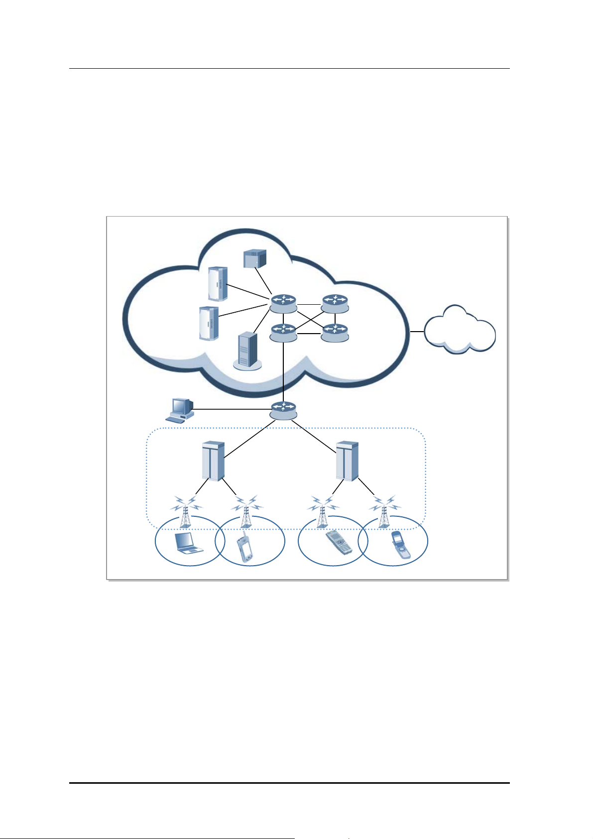
1.3 Mobile WiMAX Network Configuration
Mobile WiMAX network is composed of ASN and CSN. ACR and RAS are involved in
ASN and WSM is the Network Element (NE) to manage ACR and RAS. CSN is composed
of AAA server, HA, DNS server and PCRF server. ASN is connected with CSN by router
and switch.
The following diagram shows the composition of Mobile WiMAX network.
AA
H
Core Router/Switch
DHCP
Internet
PCRF
CSN
WSM
e Router/Switch
Ed
SN
CR
RAS
RAS
ACR
MS
Figure 1.1 Mobile WiMAX Net work Co nfig urati on
…
RAS
MS MS MS
RAS
Radio Access Station (RAS)
RAS as the system between ACR and MS has the interface with ACR and provides the
wireless connection to MS under IEEE 802.16 standards to support wireless
communication service for subscribers.
RAS carries out wireless signal exchange with MS, modulation/demodulation signal
processing for packet traffic signal, efficient use of wireless resources, packet scheduling
for Quality of Service (QoS) assurance, Admission Control, assignment of wireless
bandwidth, Automatic Repeat Request (ARQ) processing and ranging function. In addition,
RAS controls the connection for packet calls and handover.
© SAMSUNG Electronics Co., Ltd. 1-4

Mobile WiMAX Indoor RAS SPI-2210 System Description/Ed.07
Access Control Router (ACR)
ACR, which is the system between CSN and RAS, enables several RASs to interwork with
IP network, sends/receives traffic between external network and MS, and controls QoS.
The ACR interfaces with the Authentication, Authorization and Accounting (AAA) server
using the DIAMETER/RADIUS protocols and with the Policy & Charging Rules
Function(PCRF) server using the Diameter protocol . For Mobile IP services the ACR
interacts with the Home Agent.
Mobile WiMAX System Manager (WSM)
WSM provides the management environment for the operator to operate and maintain ACR
and RAS.
Home Agent (HA)
HA accesses other networks or private networks and enables Mobile IP (MIP) users to
access internet. HA interworks with ACR that performs Foreign Agent (FA) function for
Mobile IPv4 and interworks with MS to exchange data for Mobile IPv6.
Dynamic Host Configuration Protocol (DHCP) Server
The DHCP server allocates IP addresses to simple IP users. When an MS requests an IP
address to be allocated, the DHCP server allocates an IP address by interacting with the
the ACR that functions as a DHCP relay agent.
Authorization, Authentication and Accounting (AAA) Server
AAA server interfaces with ACR and carries out subscriber authentication and accounting
functions. The AAA server interfaces with ACR via Diameter/RADIUS protocol and
provides Extensible Authentication Protocol (EAP) certification.
Policy & Charging Rules Function (PCRF) Server
The PCRF server is the server that manages the service policy and interfaces with ACR via
Diameter protocol. The PCRF server sends QoS setting information for each user session
and accounting rule information to ACR.
© SAMSUNG Electronics Co., Ltd. 1-5
Mobile WiMAX Indoor RAS SPI-2210 System Description/Ed.07
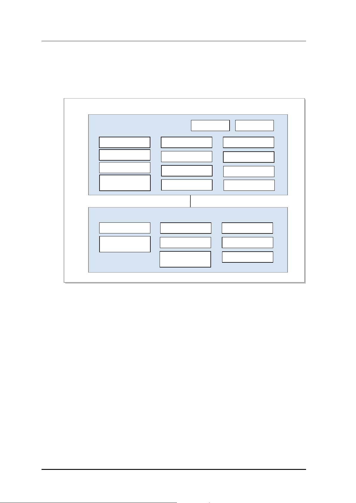
1.4 Mobile WiMAX System Functions
The figure below shows the functions of the ASN systems (ACR and RAS) based on Profile C.
Each block name complies with the standard of Mobile WiMAX NWG.
ASN
ASN-GW (ACR)
Paging Controller
Location Register
Context Function
Handover Function
(Handover Relay)
BS (RAS)
Context Function
Handover Function
(Handover Control)
Figure 1.2 Configuration of Mobile W iMA X Sy ste m Fu ncti ons (Ba sed on Pr of ile C)
Authenticator
Key Distributor
SFA
AAA Client
Key Receiver
RRC & RRA
SFM
(Admission Control)
MIP FA PMIP client
IP Packet Forwarding
Header Compression
Packet Classification
DHCP relay agent
R6
ARQ Operation
MAC PDU
Encapsulation/PHY
The ACR supports the Convergence Sublayer (CS) and performs the packet classification
and Packet Header Suppression (PHS) functions. When the ACR carries out the header
compression function, it supports ROHC defined in the NWG standard.
In addition, the ACR performs the paging controller and location register functions for a
MS in Idle Mode.
In authentication, the ACR performs the authenticator function and carries out the key
distributor function to manage the higher security key by interworking with the AAA server
as an AAA client. At this time, RAS performs the key receiver function to receive the
security key from the key distributor and manage it.
The ACR interworks with the AAA server of CSN for authentication and charging services
and with the HA of CSN for Mobile IP (MIP) service. The ACR as FA of MIP supports
Proxy MIP (PMIP).
© SAMSUNG Electronics Co., Ltd. 1-6

Mobile WiMAX Indoor RAS SPI-2210 System Description/Ed.07
The RAS performs the Service Flow Management (SFM) function to create/change/release
connections for each Service Flow (SF) and the admission control function while
creating/changing connections. In regard to the SFM function of the RAS, the ACR carries
out the SF Authentication (SFA) and SFID management functions. The ACR carries out the
SFA function to obtain the QoS information from Policy Function (PF) and apply it in the
SF creation and performs the SFID management function to create/change/release SFID
and map SF according to the packet classification.
In handover, the RAS performs the handover control function to determine the execution of
the handover and deal with corresponding handover signaling. The ACR confirms the
neighbor BS list and relays the handover signaling message to the target system.
At this time, the ACR and the RAS carries out the context function to exchange the context
information between the target system and the serving system.
The RAS provides admission control to collect/manage the MS's radio resource information and
the RAS’s own radio resource information (e.g., BSID). When load balancing is required based
on admission control results, it performs resource management through FA overriding and BS init
HO (Handover).
ASN System Function
For the detailed description about the RAS functions, refer to Chapter 2 of this
system description. For the description about the ACR functions, refer to the
system description for ACR provided by Samsung.
© SAMSUNG Electronics Co., Ltd. 1-7

Mobile WiMAX Indoor RAS SPI-2210 System Description/Ed.07
This page is intentionally left blank.
© SAMSUNG Electronics Co., Ltd. 1-8

Mobile WiMAX Indoor RAS SPI-2210 System Description
CHAPTER 2. Overview of Indoor SPI-
2210
2.1 Introduction to Indoor SPI-2210
The indoor SPI-2210, RAS of Mobile WiMAX, is controlled by ACR and connects Mobile
WiMAX calls to MS.
The indoor SPI-2210 interfaces with MS via a wireless channel observing the Mobile
WiMAX standard (IEEE 802.16) and provides high-speed data service and multimedia
service in wireless broadband.
To this end, the indoor SPI-2210 provides the following functions:
modulation/demodulation of packet traffic signal, scheduling and radio bandwidth
allocation to manage air resources efficiently and ensure Quality of Service (QoS), Automatic
Repeat Request (ARQ) processing, ranging function, connection control function to
transmit the information on the indoor SPI-2210 and set/hold/disconnect the packet call
connection, handover control and ACR interface function and system operation
management function.
The indoor SPI-2210 interfaces with ACR in one way of Fast Ethernet/Gigabit Ethernet
and can exchange various control signals and traffic signals stably.
The indoor SPI-2210 is installed in the indoor environment and managed in the omni or
sector method according to the property of the installed area. In addition, the indoor SPI2210 supports the capacity of the maximum 3Carrier/3Sector and MIMO only with the
basic rack.
The characteristics of the indoor SPI-2210 are as follows:
Application of the OFDMA Method
OFDMA is used to transmit data to several users simultaneously by using the sub-carrier
allocated to each user and transmit data by allocating one or more sub-carriers to a specific
subscriber according to the channel status and the transmission rate requested by a user.
In addition, since it can select the sub-carriers with excellent features for each subscriber
and allocate them to the subscribers when some subscribers divide and use the whole subcarrier, it can raise the data throughput by distributing the resources efficiently.
© SAMSUNG Electronics Co., Ltd. 2-1

Mobile WiMAX Indoor RAS SPI-2210 System Description/Ed.07
Support of Broadband Channel Bandwidth
The indoor SPI-2210 supports wide bandwidth of 5/10 MHz per carrier and high-speed and
high capacity packet service.
Support of 3Carrier/3Sector
The indoor SPI-2210 can support 3Carrier/3Sector by the basic rack.
Support of MIMO
The indoor SPI-2210 basically supports MIMO of 2Tx/2Rx RF path. There are two
methods of MIMO as follows;
y Downlink
Space Time Coding (STC): method for raising reliability of link
Spatial Multiplexing (SM): method for raising data transmission rate
y Uplink
Collaborative SM (CSM): Doubled frequency efficiency
Support of Frequency Reuse Pattern (FRP)
The indoor SPI-2210 supports FRP N=1 that provides the service to 3-sector by using a
carrier and FRP N=3 that provides the service to 3-sector by using different carriers.
A service provider can efficiently operate its own frequency resources by using the FRP
function.
Support of 4-Branch Rx Diversity (Optional)
The indoor SPI-2210 supports 4-branch Rx diversity providing four Rx paths to each sector
to raise the Rx performance. In the indoor SPI-2210, Mobile WiMAX base station RF
Receiver (MRR), an Rx module, should be additionally mounted to support 4-branch Rx
diversity.
Support of Various Frequency Allocation
The indoor SPI-2210 supports various frequency allocation methods such as contiguous
carrier, noncontiguous carrier, FRP N=1 or FRP N=3. The indoor SPI-2210 can apply RF
combiner optionally to such frequency allocation methods.
Support of Beamforming (Optional)
The indoor SPI-2210 is designed as the structure to support beamforming later. The indoor
SPI-2210 mitigates the interference efficiently by uplink and downlink beamforming to
raises the average capacity and expand the data coverage. Also the indoor SPI-2210 needs
the process to calibrate the reciprocity between uplink channel and downlink channel.
Schedule to Provide the System Feature
For the schedule to provide the features described in this system description, see
separate document.
© SAMSUNG Electronics Co., Ltd. 2-2

Mobile WiMAX Indoor RAS SPI-2210 System Description/Ed.07
2.2 Main Functions
The main functions of the indoor SPI-2210 are as follows:
y Physical layer processing function
y Call processing function
y IP processing function
y Auxiliary device interface function
y Convenient operation and maintenance function
2.2.1 Physical Layer Processing Function
OFDMA Ranging
The ranging supported by the OFDMA system is roughly divided by the uplink timing
synchronization method and the contention based bandwidth request method.
y Uplink Timing Synchronization
In the uplink timing synchronization method, the indoor SPI-2210 detects the timing
error of the uplink signal by using the ranging code transmitted from MS and transmits
the timing correction command to each MS to correct the transmission timing of the uplink.
The uplink timing synchronization method has initial ranging, periodic ranging,
handover ranging, etc.
y Contention Based Bandwidth Request
In the contention based bandwidth request method, the indoor SPI-2210 receives the
bandwidth request ranging code from each MS and allocates uplink resources to the
corresponding MS to enable to transmit the bandwidth request header.
The contention based bandwidth request method has bandwidth request ranging or
something.
Channel Encoding/Decoding
The indoor SPI-2210 carries out the Forward Error Correction (FEC) encoding for the
downlink packet created in the upper layer by using Conventional Turbo Code (CTC).
On the contrary, it decodes the uplink packet received from the MS after demodulating.
Modulation/Demodulation
The indoor SPI-2210 carries out the FEC encoding for the downlink packet created in the
upper layer and modulates the encoded packet into the QAM signal. In addition, the indoor
SPI-2210 demodulates and decodes the uplink packet received from MS.
© SAMSUNG Electronics Co., Ltd. 2-3

Mobile WiMAX Indoor RAS SPI-2210 System Description/Ed.07
OFDMA Sub-carrier Allocation
The subchannelization is the process to tie the sub-carriers of OFDMA as a transmission
unit after grouping them by a certain rule. The indoor SPI-2210 performs the
subchannelization to mitigate the interference between cells.
The indoor SPI-2210 maps the column of the modulated downlink QAM symbol structure
with each sub-carrier and carries out the subchannelization when the column of the QAM
symbol structure is transmitted to the MS over the wireless line.
In such way, the indoor SPI-2210 transmits the column of the QAM symbol structure to the
MS via the sub-carriers pertained to each subchannel.
DL/UL MAP Construction
The indoor SPI-2210 informs the air resources for the uplink and the downlink to the MS
by using DL/UL MAP. The DL/UL MAP consists of the scheduling information of the
indoor SPI-2210 and includes various control information for the MS.
Power Control
The indoor SPI-2210 carries out the power control function for the uplink signal received
from multiple MSs and then set the power intensity of the uplink signal to a specific level.
The indoor SPI-2210 transmits the power correction command to each MS and then makes
the MS power intensity be the level required in the indoor SPI-2210 when the MS transmits
the modulated uplink signal in a specific QAM modulation method.
Hybrid-ARQ (H-ARQ) Operation
H-ARQ is the physical layer retransmission method using the stop-and-wait protocol.
The indoor SPI-2210 carries out the H-ARQ function and raises data throughput by retransmitting or combining the frame from the physical layer to minimize the effect
attending to the change of wireless channel environment or the change in the interference
signal level.
MIMO
The indoor SPI-2210 provides the MIMO function as follows according to Mobile WiMAX
Wave 2 Profile:
y Downlink
Matrix A (Space-Time Coding)
Transmission ratio of the Matrix A or Space-Time Coding (STC) is 1 and equal to
that of Single Input Single Output (SISO). However The Matrix A or the STC
reduces the error of the signal received from the MS by raising the stability of the
signal received from the MS by means of the Tx diversity. This technology is, also,
effective in Signal to Noise Ratio (SNR) and provides excellent performance even
when the MS moves in high speed.
− Matrix B (Spatial Multiplexing, vertical encoding)
Matrix B or Spatial Multiplexing (SM) method raises the effectiveness of the
frequency by the number of antennas the transmission ratio in comparison with SISO.
This technology is effective when the reception SNR is high.
© SAMSUNG Electronics Co., Ltd. 2-4

Mobile WiMAX Indoor RAS SPI-2210 System Description/Ed.07
y Uplink
− Collaborative SM (CSM)
Collaborative SM is the technology that doubles the frequency efficiency in view
of the indoor SPI-2210 as two MSs with each individual antenna send data
simultaneously by using the same channel.
Beamforming
The indoor SPI-2210 can carry out the following beamforming function later according to
Mobile WiMAX Wave 2 Profile: For the beamforming, the indoor SPI-2210 is designed on
the basis of 4Tx and 4Rx.
y Downlink
DL dedicated pilots for Partial Usage of Subchannels (PUSC) and B-AMC (2¯3)
y Uplink
UL sounding channel (type A) with decimation and cyclic shift
UL PUSC and B-AMC (2¯3)
The beamforming operation method following the Wave 2 Profile is as follows:
1) If an MS in a specific area transmits the sounding signal to the indoor SPI-2210, the
indoor SPI-2210 analyzes this signal.
2) The indoor SPI-2210 estimates an appropriate beamforming coefficient on the basis of
the result analyzed in step 1).
3) The indoor SPI-2210 carries out the beamforming for the uplink and the downlink.
Since the uplink and downlink channels have the high correlation in TDD method, the
beamforming can be supported.
2.2.2 Call Processing Function
Cell Initialization Function
The indoor SPI-2210 announces the MAC Management message such as DCD/UCD/
MOB_NBR-ADV to the cell area in service periodically to enable the MS receiving the
message to carry out the appropriate call processing function.
Call Control and Wireless Resource Allocation Function
The indoor SPI-2210 enables an MS to enter to or exit from the network. When an MS enters
to or exit from the network, the indoor SPI-2210 transmits/receives the signaling message
required for call processing via R1 interface with the MS or R6 interface with ACR.
The indoor SPI-2210 allocates various management/transport Connection Identifier (CID)
required for the network entry and service to a MS. When the MS exit from the network,
the indoor SPI-2210 collects and release the allocated CID.
© SAMSUNG Electronics Co., Ltd. 2-5

Mobile WiMAX Indoor RAS SPI-2210 System Description/Ed.07
Handover
The indoor SPI-2210 carries out the signaling and bearer processing for inter-sector HO
(Handover), inter-ACR HO and inter-carrier HO. At this time, ACR relays the handover
message between serving RAS and target RAS through the R6 interface.
To minimize the traffic disconnection in inter-RAS HO, the indoor SPI-2210 performs the
data switching function. In handover, the indoor SPI-2210 enables the serving RAS to
switch the user data in queuing to the target RAS and, therefore, the MS to recover the
traffic without loss.
Handover Procedure
For the detailed handover procedure, refer to Chapter 4 ‘Message Flow’.
Support of Sleep Mode
Sleep mode is the mode defined to save the MS power under IEEE 802.16 standard and
indicates the status that air resources allocated to an MS are released when the MS does not
need traffic reception/transmission temporarily. If the MS in Sleep Mode needs the traffic
reception/transmission, the MS returns to the normal status immediately.
Both Idle Mode and Sleep Mode are modes to save the MS power. The Idle Mode relea se
all service flows allocated to an MS, while the Sleep Mode releases only the air resources
between the MS and RAS temporarily, continuously keeping the service flow information
allocated to the MS.
The indoor SPI-2210 carries out the related call processing function by receiving/sending
the signaling message required for the MS's status transition into Sleep Mode and the MS
return from the Sleep Mode to Awake Mode.
Admission Control (AC) Function
If the indoor SPI-2210 receives the call setup request, such as network entry, QCS and
handover, from an MS, it monitors the traffic and signaling load for each subcell and the
number of user in Active/Sleep Mode and performs the AC function to prevent the system
overload.
AC can be roughly divided into AC by MS and AC by service flow.
y AC by MS
If the number of users who the subcell is in Active/Sleep Mode exceeds the threshold
when the indoor SPI-2210 receives the call setup request from an MS, it rejects the
call setup request of the MS.
y AC by service flow
When service flow is added, the indoor SPI-2210 checks if the air resources of the
requested subcell exceed the threshold and determines the creation of the service
© SAMSUNG Electronics Co., Ltd. 2-6

Mobile WiMAX Indoor RAS SPI-2210 System Description/Ed.07
MAC ARQ Function
The indoor SPI-2210 carries out the ARQ function of the MAC layer. In packet data exchange,
ARQ transmits SDU from the transmission side to the ARQ block and retransmits the
packet according to the ARQ feedback information received from the reception side to
raise the reliability of data communication.
The indoor SPI-2210 carries out the following function for the service flows applying ARQ:
y Creation and transmission concerned with ARQ operation
y Feedback processing depending on ARQ types
y Block processing (fragmentation/reassemble/retransmission) depending on ARQ types
y ARQ timer/window management
QoS Support Function
The packet traffic exchanged between ACR and indoor SPI-2210 is delivered to the modem
in the indoor SPI-2210. At this time, the indoor SPI-2210 allocates the queue in the modem
to each service flow that QoS type is specified to observe the QoS constraint given for each
QoS class or service flow and performs the strict-priority scheduling according to the priority.
The modem that receives the packet traffic performs the scheduling by using the uplink/downlink
algorithm, such as Proportional Fair (PF) or Round Robin (RR) and transmits the
scheduled allocation information to an MS through DL/UL MAP.
The MS receiving the DL/UL MAP checks the air resources allocated to the MS and
modulates/demodulates the downlink packet or transmits the uplink packet from the
allocated uplink area.
Since the indoor SPI-2210 provides the QoS monitoring function, it can compile statistics
on packets unsatisfying the latency requested from the QoS parameter according to TDD
frames and report the statistics to an operator via the OAM interface.
© SAMSUNG Electronics Co., Ltd. 2-7
 Loading...