

Page 1

Alignment and Adjustments
Samsung Electronics 4-1
4. Alignment and Adjustments
1. Usually, a color TV-VCR needs only slight
touch-up adjustment upon installation. Check
the basic characteristics such as height,
horizontal and vertical sync and focus.
2. Observe the picture for good black and white
details. There should be objectionable color
shading; if color shading is present,
demagnetize, perform purity and convergence
adjustments described below.
3. Use the specified test equipment or its
equivalent.
4. Correct impedance matching is essential.
5. Avoid overload. Excessive signal from a
sweep generator might overload the front-end
of the TV. When inserting signal markers, do
not allow the marker generator to distort test
results.
6. Connect the TV only to an AC power source
with voltage and frequency as specified on the
backcover nameplate.
7. Do not attempt to connect or disconnect any
wires while the TV is turned on. Make sure
that the power cord is disconnected before
replacing any parts.
8. To protect against shock hazard, use an
isolation transformer.
CAUTION : There is no high voltage adjustment on this
chassis. The B+ power supply should be +135 volts (with
full color- bar input and normal picture level).
1. Connect a digital voltmeter to the second
anode of the picture tube.
2. Turn on the TV. Set the Brightness and
Contrast controls to minimum (zero beam
current).
3. Adjust the Brightness and contrast controls to
both extremes. Ensure that the high voltage
does not exceed 32 KV under any conditions.
1. Enter & Concel the Factory Mode
(1) Usual Remote Control
Enter : PICTURE OFF -> DISPLAY KEY ->
MENU KEY -> MUTE KEY -> POWER ON
(Press each remote control key with in 3
seconds).
Cancel : POWER OFF -> ON
(2) Factory Remote Mode
Enter : DISPLAY KEY -> FACTORY KEY
(Press each remote control key with in 3
seconds).
Cancel : POWER OFF -> ON
Press the FACTORY key twice at intervals
of at lease 1 second.
(Enter the AGING Mode once)
(3) Set Value When Entering the Factory Mode
- Picture Mode & Sound Mode are set to
the standard data.
(4) Adjustments
- CH.UP/DOWN Key : Use to select the
item you want.
- VOLUME UP/DOWN Key : Increases or
decreases the value of data.
- MENU Key : Use to save the current set
value in EEPROM and exit to the upper
mode.
- Use the TV/VIDEO Key the conver to the
AV Mode.
4-2 High voltage Check
4-1 General Alignment Instructions
4-3 FACTORY MODE CONTROL
Page 2
Alignment and Adjustments
4-2 Samsung Electronics
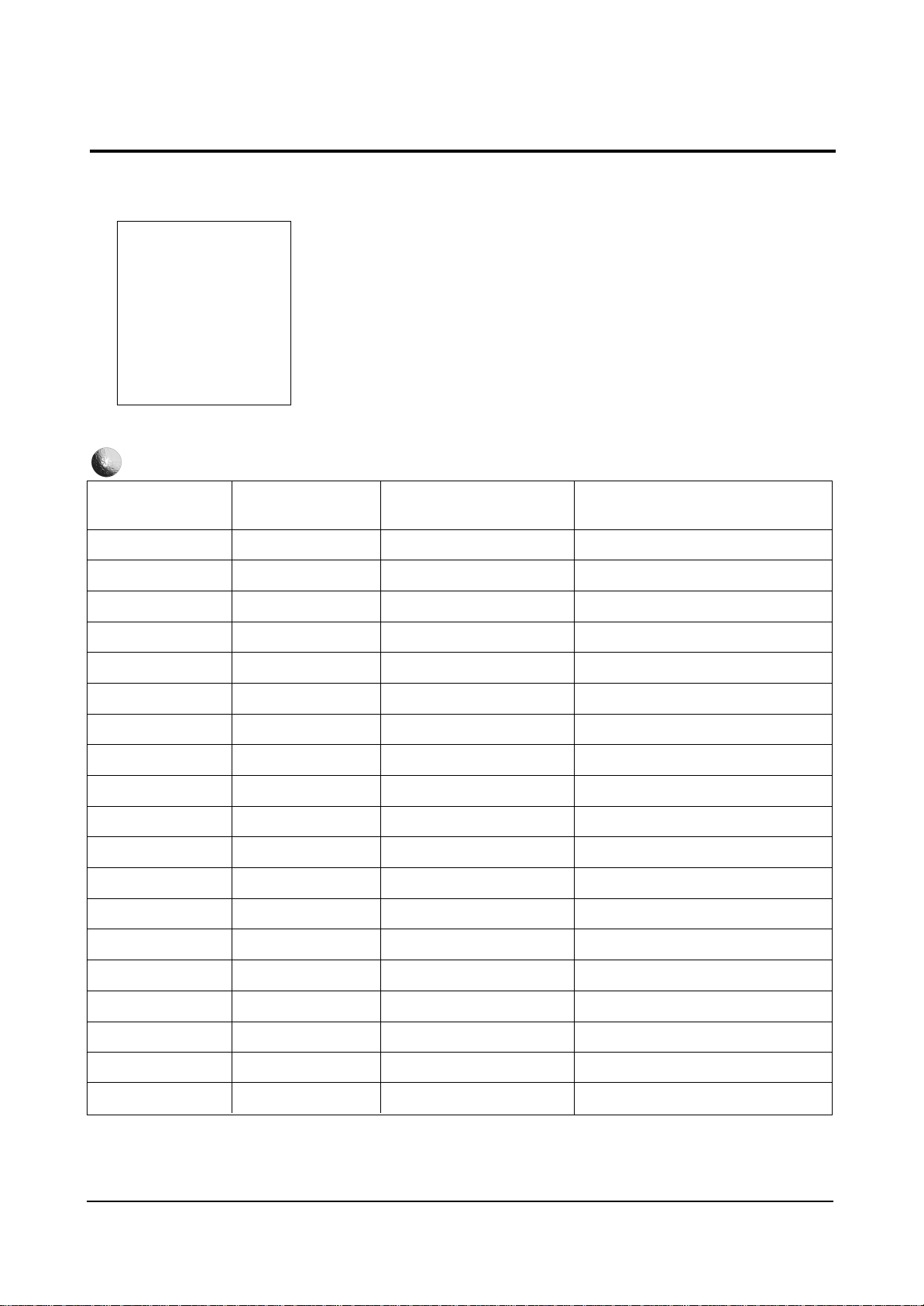
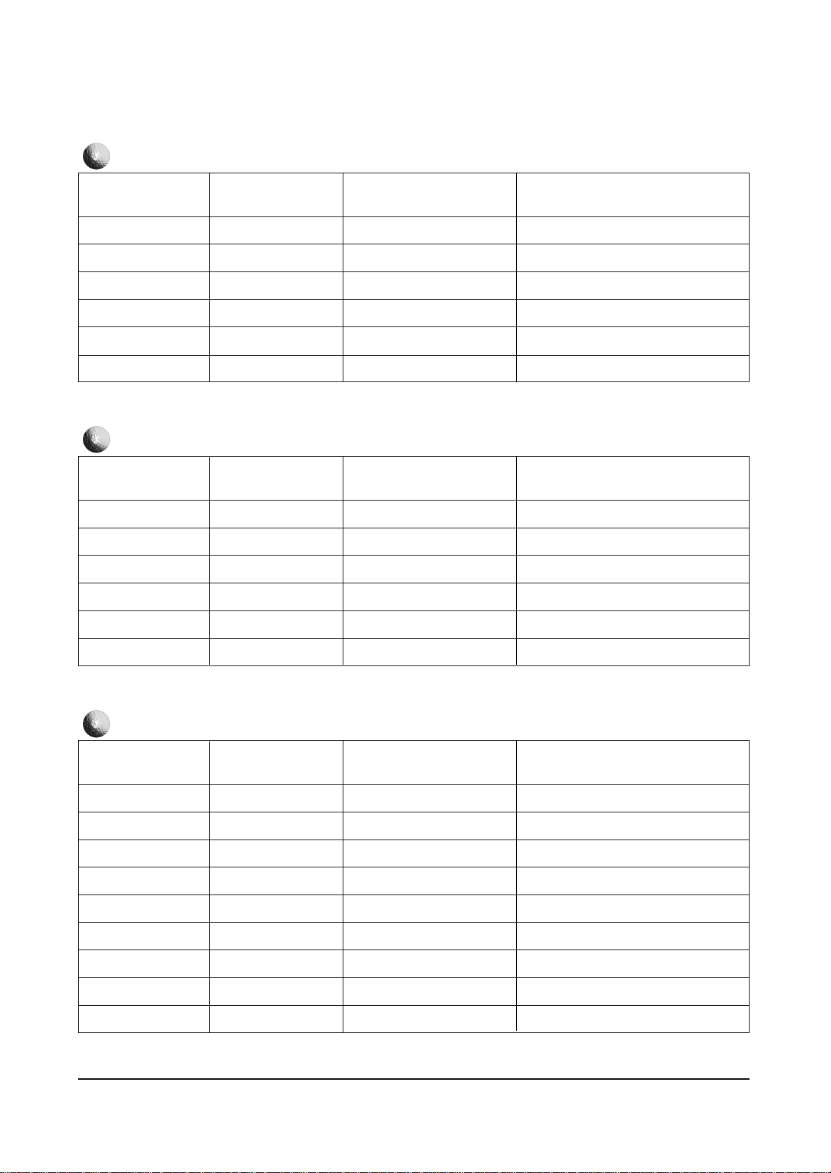
R Drive
B Drive
G Drive
Gamma
R Cutoff
B Cutoff
G Cutoff
Sub Cont
Sub Brt.
Sub Color
Sub Tint
V Peaking
TTX Cont
TTX Bright
PIP Cont
PIP Bright
CG R Contrast
CG G Contrast
CG B Contrast
0 ~ 63
0 ~ 63
0 ~ 63
0 ~15
0 ~ 63
0 ~ 63
0 ~ 63
0 ~15
0 ~ 63
0 ~15
0 ~15
0 ~12
0 ~15
0 ~ 63
0 ~15
0 ~15
0 ~ 63
0 ~ 63
0 ~ 63
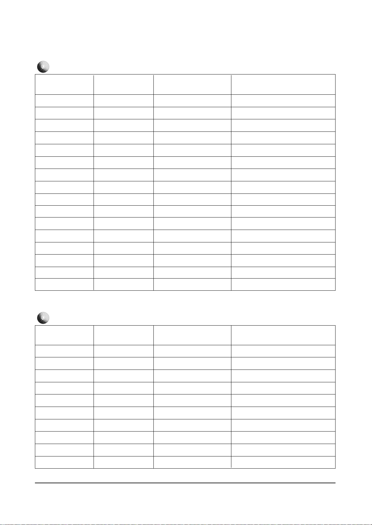
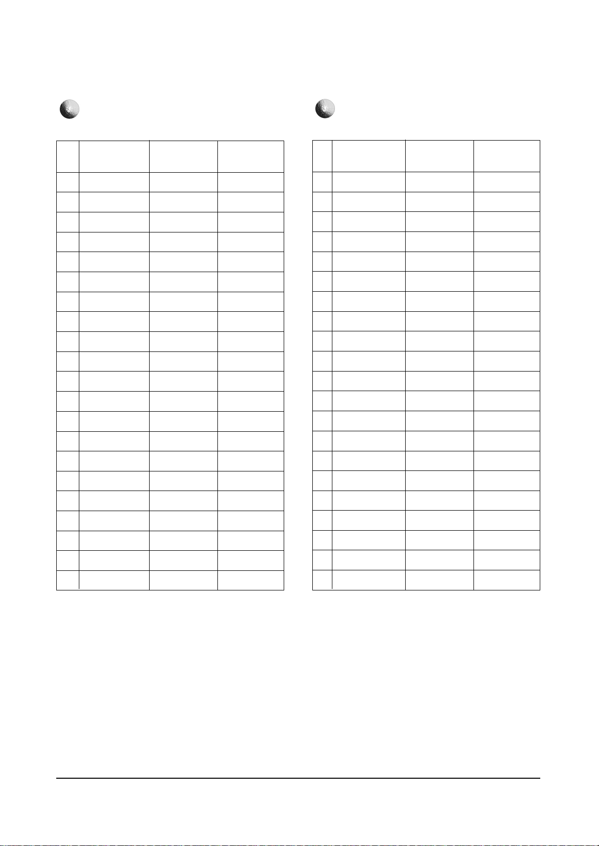
4-4 FACTORY MODE MENU
4-4-1 CW MODEL
FUNCTION RANGE
INITIAL DATA
31
31
31
12
31
31
31
7
31
7
7
7
10
10
0
0
40
40
40
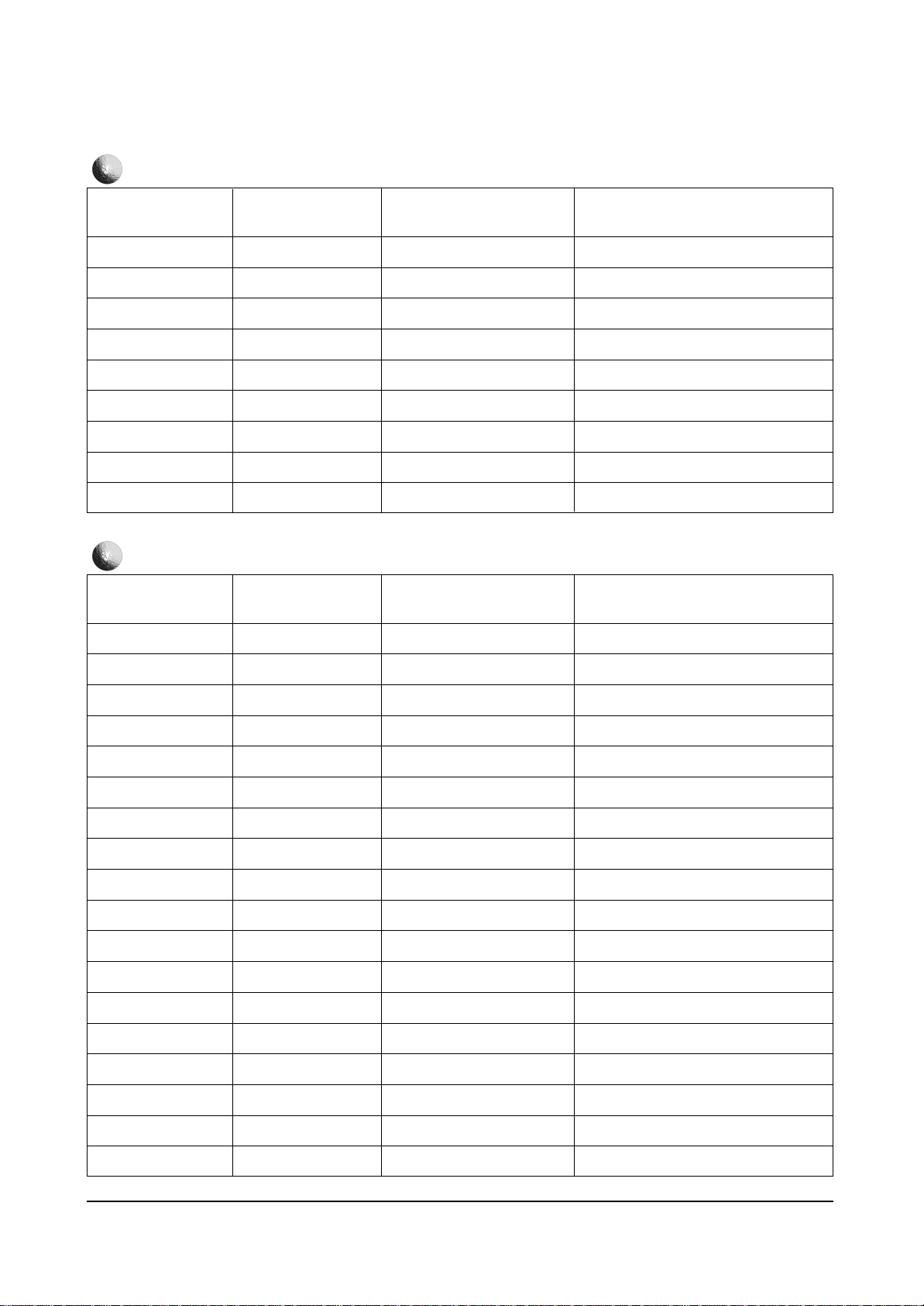
Service Mode
Video Adjustment
Y.C-Delay
Deflection normal
Deflection VGA
Option byte
Reset
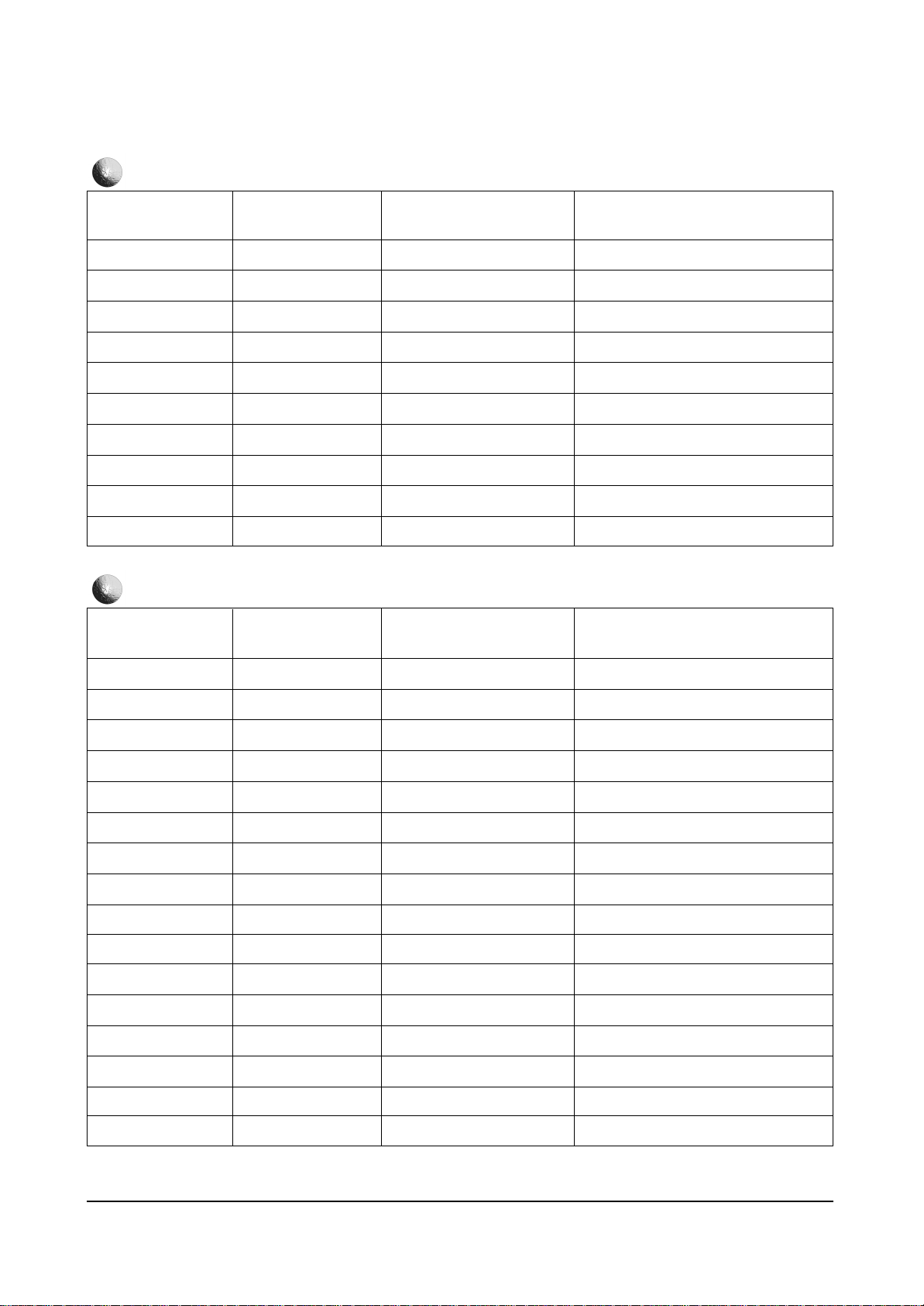
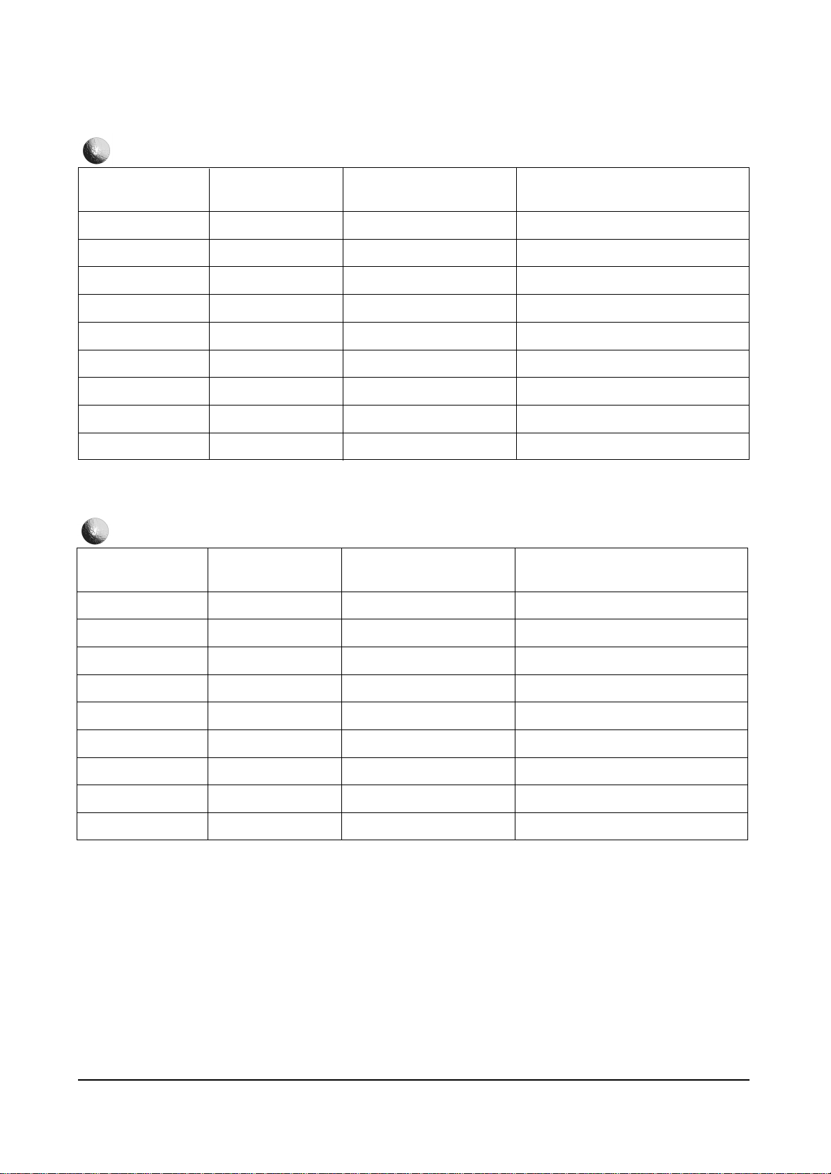
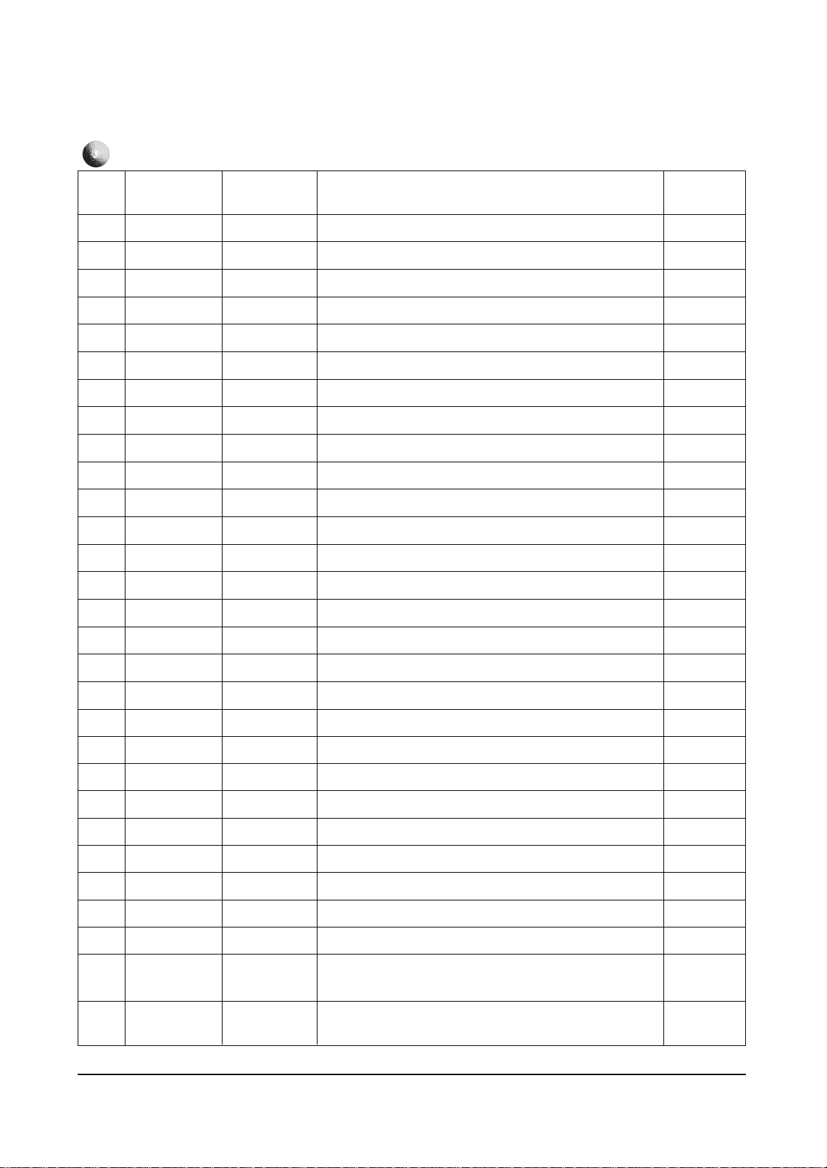
VIDEO ADJUSTMENT
REMARK
Page 3
Alignment and Adjustments
Samsung Electronics 4-3
PAL-B/G
PAL-D/K/L
PAL-I
SECAM-B/G
SECAM-D/K/L
NTSC
PAL-AV
SECAM-AV
NTSC-AV
DVD
0 ~15
0 ~15
0 ~15
0 ~15
0 ~15
0 ~15
0 ~15
0 ~15
0 ~15
0 ~15
FUNCTION RANGE
INITIAL DATA
6
8
8
4
6
7
5
4
6
9
Y.C-DELAY
REMARK
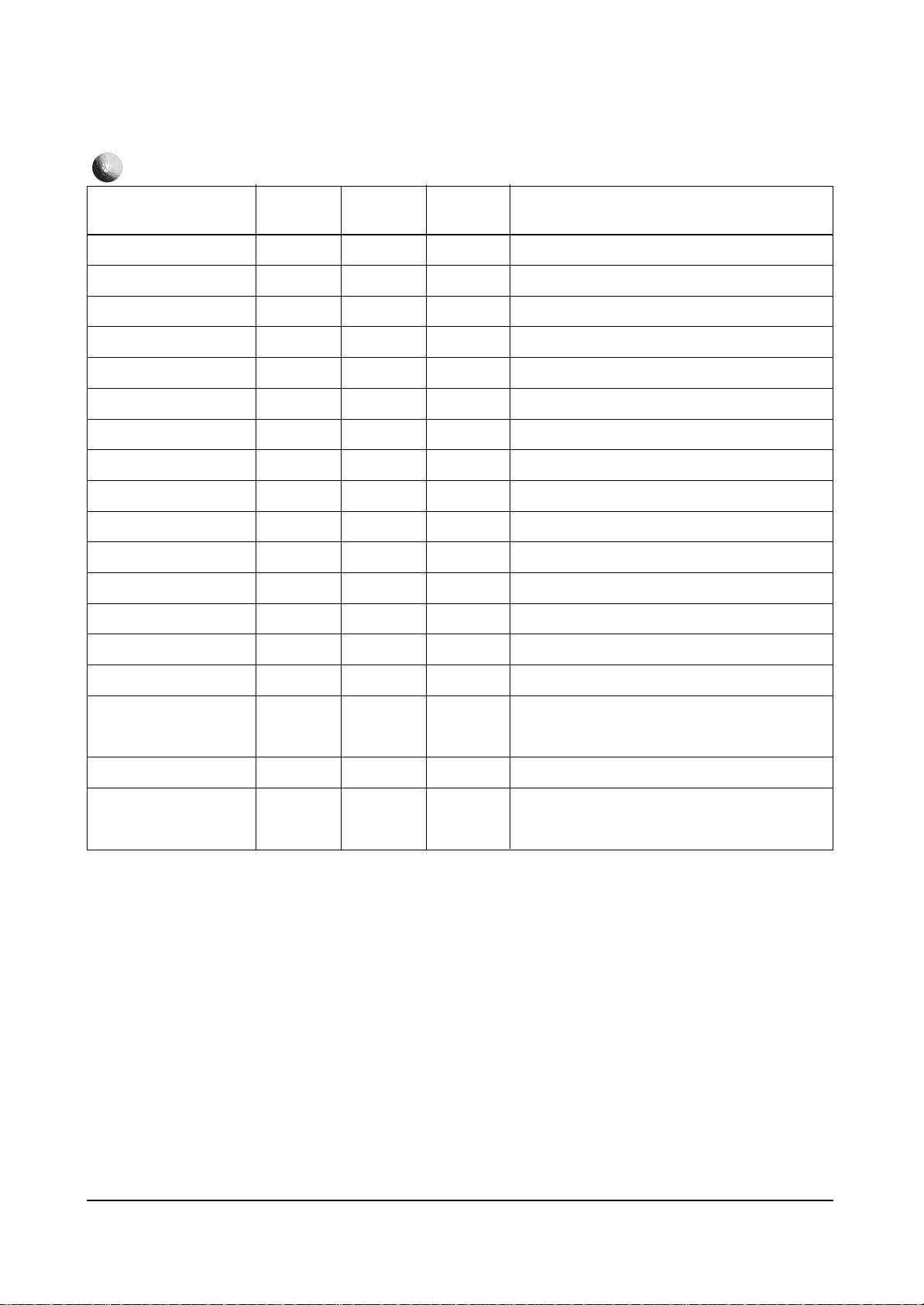
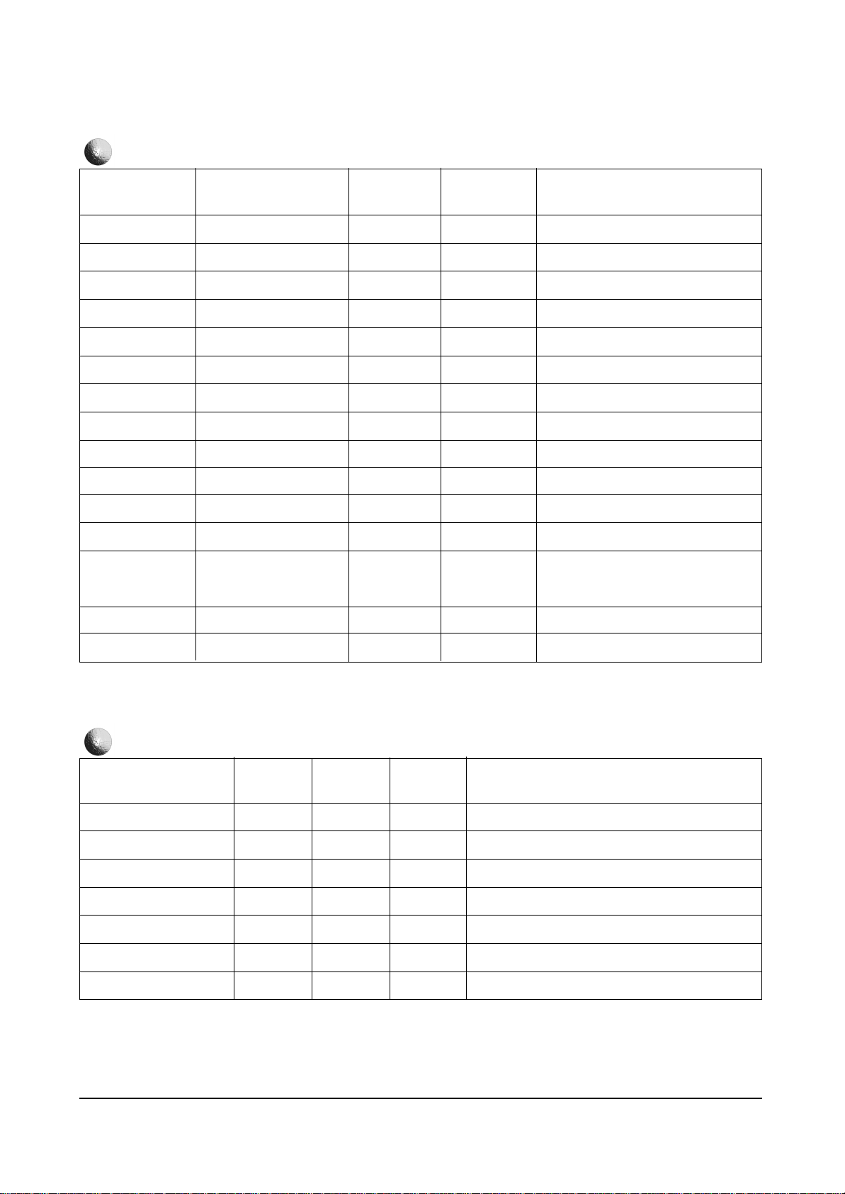
P.V-SIZE
P.V-SFT
P.V-LIN
P.S-CORR
P.EW-WTH
P.EW-PBL
P.H-SFT
P.EW-TPZ
P.BOW
P.ANGLE
P.EW-UPCR
P.EW-LOCR
P.HOR-EHT
P.VER-EHT
P.INT. VOL. REF
P.HSYNC DELAY
-128 ~ +127
-128 ~ +127
-128 ~ +127
-128 ~ +127
-128 ~ +127
-128 ~ +127
-64 ~ +63
-128 ~ +127
-128 ~ +127
-128 ~ +127
-128 ~ +127
-128 ~ +127
0 ~ +255
0 ~ +255
-16 ~ +15
-128 ~ +127
FUNCTION RANGE
INITIAL DATA
-40
-39
0
0
+28
-27
-22
0
0
0
0
0
0
0
0
+10
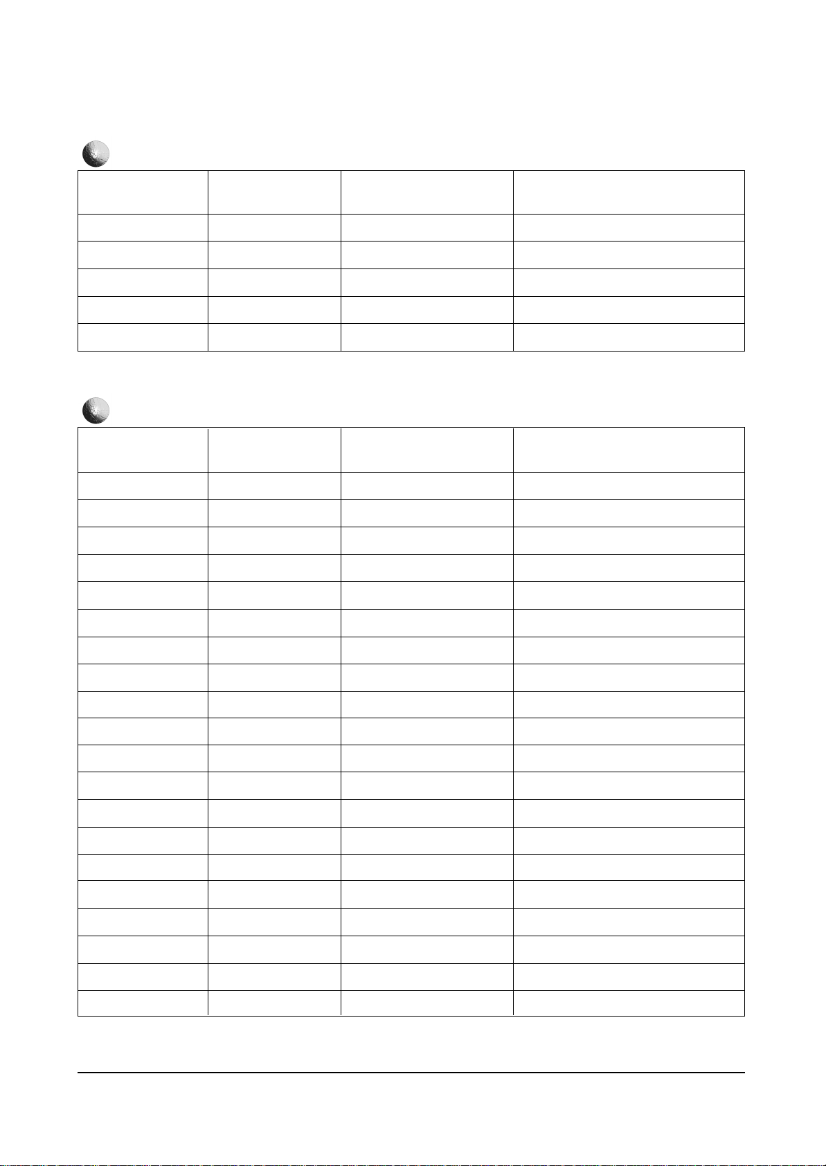
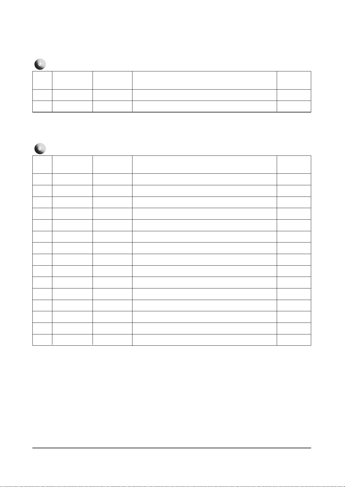
DEFLECTION NORMAL
REMARK
Page 4
Alignment and Adjustments
4-4 Samsung Electronics
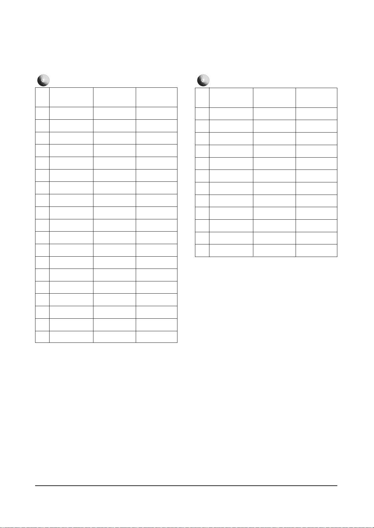
P.PHP
P.PVP
P.PHS
P.PVS
P.CG V-AMP OFFSET
0 ~ 255
0 ~ 255
0 ~15
0 ~15
-128 ~ +127
FUNCTION RANGE
INITIAL DATA
32
32
0
0
+30
DEFLECTION NORMAL
REMARK
LIMIT LEVEL
SYSEM
CLP-MSK
ABL-MODE
ABL-TH
DTV-SYNC
CR-OFFSET1
CB-OFFSET1
CR-OFFSET2
CB-OFFSET2
CTI-LEVEL
R-Y/R
R-Y/B
G-Y/R
G-Y/B
LRGB2-LEVEL
PABL-LEVEL
BLK-BOTTOM
SUB-SHP
SUB-FO
0 ~ 3
0 ~ 3
0 ~ 3
0 ~ 3
0 ~ 3
0 ~ 255
0 ~ 15
0 ~ 15
0 ~ 15
0 ~ 15
0 ~ 3
0 ~ 15
0 ~ 15
0 ~ 15
0 ~ 15
0 ~ 15
0 ~ 15
0 ~ 15
0 ~ 3
0 ~ 3
FUNCTION RANGE
INITIAL DATA
0
1
0
1
1
69
10
10
7
7
1
3
7
15
2
7
15
15
3
2
PICT. IMPROVE
REMARK
Page 5
Alignment and Adjustments
Samsung Electronics 4-5
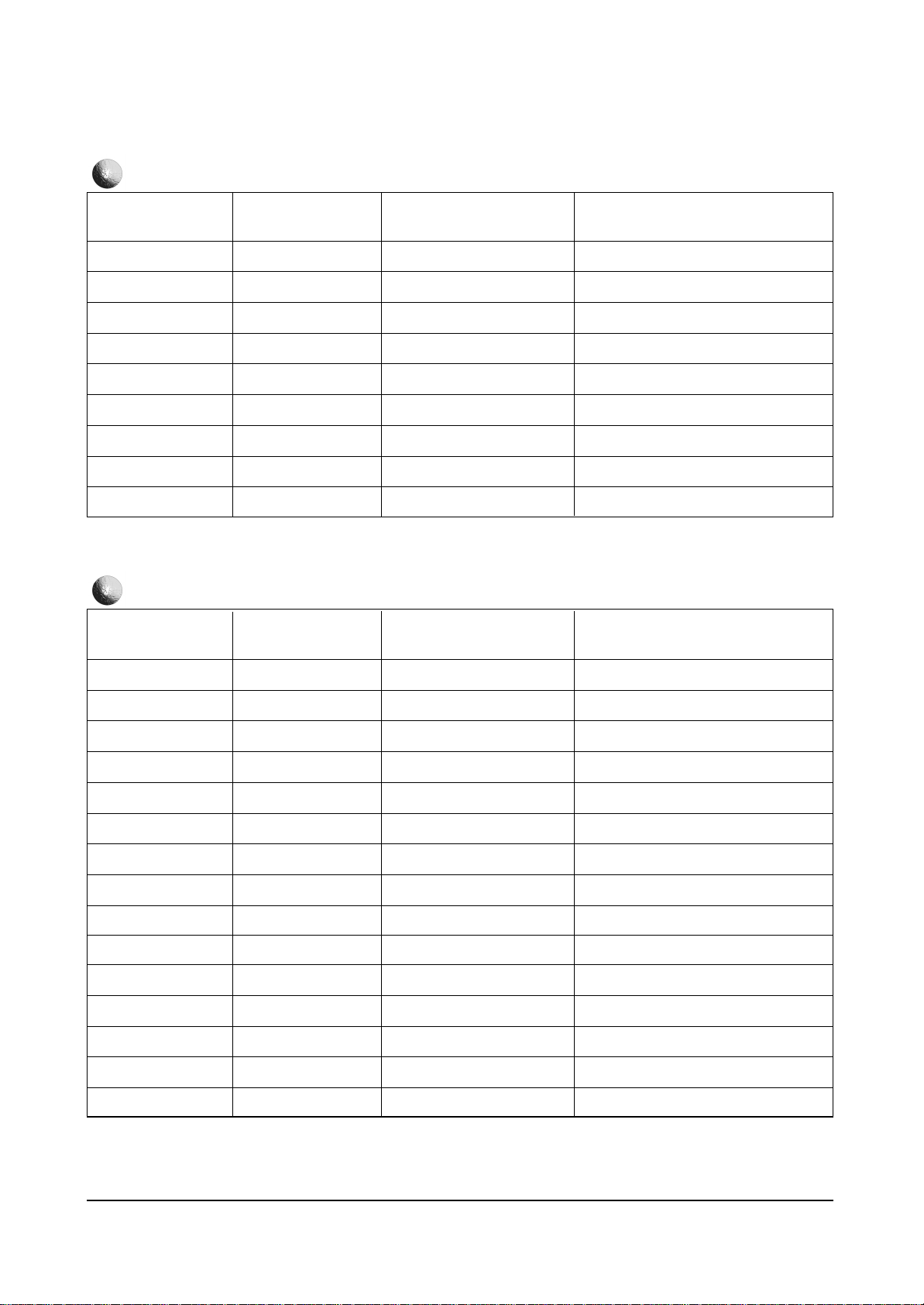
PRE-OVER
LT1-LEVEL
VM-LEVEL
VM-DELAY
DC-TRAN
D-PIC
DCTI
BPF-LPF
HPE-CORING
0 ~ 3
0 ~ 3
0 ~ 3
0 ~ 3
0 ~ 3
0 ~ 3
0 ~ 255
0 ~ 255
0 ~ 255
FUNCTION RANGE
INITIAL DATA
3
2
2
3
3
3
8
72
8
PICT. IMPROVE
REMARK
SYSTEM
CR-OFFSET1
CB-OFFSET1
R-Y/R
R-Y/B
G-Y/R
G-Y/B
SUB-SHP
SUB-FO
PRE-OVER
LT1-LEVEL
VM-LEVEL
VM-DELAY
DC-TRAN
D-PIC
0 ~ 3
0 ~ 15
0 ~ 15
0 ~ 15
0 ~ 15
0 ~ 15
0 ~ 15
0 ~ 3
0 ~ 3
0 ~ 3
0 ~ 3
0 ~ 3
0 ~ 3
0 ~ 3
0 ~ 3
FUNCTION RANGE
INITIAL DATA
2
7
9
2
15
7
0
0
0
0
0
0
0
3
3
PICT. IMPROVE
REMARK
Page 6
Alignment and Adjustments
4-6 Samsung Electronics
CR-OFFSET1
CB-OFFSET1
R-Y/R
R-Y/B
G-Y/R
G-Y/B
0 ~ 15
0 ~ 15
0 ~ 15
0 ~ 15
0 ~ 15
0 ~ 15
FUNCTION RANGE
INITIAL DATA
6
11
2
15
7
0
PICT. IMPRV. SECA
REMARK
CR-OFFSET1
CB-OFFSET1
CT1-LEVEL
DCTI
BPF-LPF
HPE-CORING
0 ~ 15
0 ~ 15
0 ~ 3
0 ~ 255
0 ~ 255
0 ~ 255
FUNCTION RANGE
INITIAL DATA
7
9
1
0
72
8
PICT. IMPRV. DVD
REMARK
SYSTEM
CLP-MASK
DTV-SYNC
CR-OFFSET1
CB-OFFSET1
CTI-LEVEL
R-Y/R
R-Y/B
G-Y/R
0 ~ 3
0 ~ 3
0 ~ 255
0 ~ 15
0 ~ 15
0 ~ 3
0 ~ 15
0 ~ 15
0 ~ 15
FUNCTION RANGE
INITIAL DATA
0
0
0
0
0
0
0
0
0
PICT. IMPRV. 480p
REMARK
Page 7
Alignment and Adjustments
Samsung Electronics 4-7
G-Y/B
SUB-SHP
SUB-FO
PRE-OVER
LTI-LEVEL
VM-LEVEL
VM-DELAY
DC-TRAN
D-PIC
0 ~ 15
0 ~ 3
0 ~ 3
0 ~ 3
0 ~ 3
0 ~ 3
0 ~ 3
0 ~ 3
0 ~ 3
FUNCTION RANGE
INITIAL DATA
0
0
0
0
0
0
0
0
0
PICT. IMPRV. 480P
REMARK
SYSTEM
CLP-MSK
DTV-SYNC
CR-OFFSET1
CB-OFFSET1
CTI-LEVEL
R-Y/R
R-Y/B
G-Y/R
G-Y/B
SUB-SHP
SIB-FO
PRE-OVER
LTI-LEVEL
VM-LEVEL
VM-DELAY
DC-TRAN
D-PIC
0 ~ 3
0 ~ 3
0 ~ 255
0 ~ 15
0 ~ 15
0 ~ 3
0 ~ 15
0 ~ 15
0 ~ 15
0 ~ 15
0 ~ 15
0 ~ 3
0 ~ 3
0 ~ 3
0 ~ 3
0 ~ 3
0 ~ 3
0 ~ 3
FUNCTION RANGE
INITIAL DATA
0
0
0
0
0
0
0
0
0
0
0
0
0
0
0
0
0
0
PICT. IMPRV. 1080
REMARK
Page 8
Alignment and Adjustments
4-8 Samsung Electronics
WIDE
EUROPE
ENGLISH
ON
SCART
OFF
ON
ON
ON
CW
ON
ON
OFF
OFF
ON
W-EUROPE
ON
STANDARD
OPTION BYTE
SP55W3HF
SP47W3HF
SIM-826HEW OPTION-BYTE
SP65W3HF REMARK
CRT
LANGUAGE GROUP
LANGUAGE
ATM
SCRT/RCA
VGA
PLUG&PLAY
DOLBY PROLOGIC
PIP
CW/CS
LNA
CHILD-LOCK
HP JACK IDENT
TOP TTX
HIGH DEVIATION
TTX GROUP
GARRIER MUTE
STANDARD
WIDE
EUROPE
ENGLISH
ON
SCART
OFF
ON
ON
ON
CW
ON
ON
OFF
OFF
ON
W-EUROPE
ON
STANDARD
WIDE
EUROPE
ENGLISH
ON
SCART
OFF
ON
ON
ON
CW
ON
ON
OFF
OFF
ON
W-EUROPE
ON
STANDARD
WIDE <--> 4:3
EUROPE <--> ASIA
EIGHTEEN LANGUAGES
ON <--> OFF
SCART <--> RCA
ON <--> OFF
ON <--> OFF
ON <--> OFF
ON <--> OFF
CW <--> CS
ON <--> OFF
ON <--> OFF
ON <--> OFF
ON <--> OFF
ON <--> OFF
E-EUROPE -> RUSSIAN -> ARABIC
-> ICELANDIC -> HEBREW
ON <--> OFF
STANDARD -> SPORT -> MILD
-> NATURAL -> CUSTOM -> NDEN
Page 9
Alignment and Adjustments
Samsung Electronics 4-9
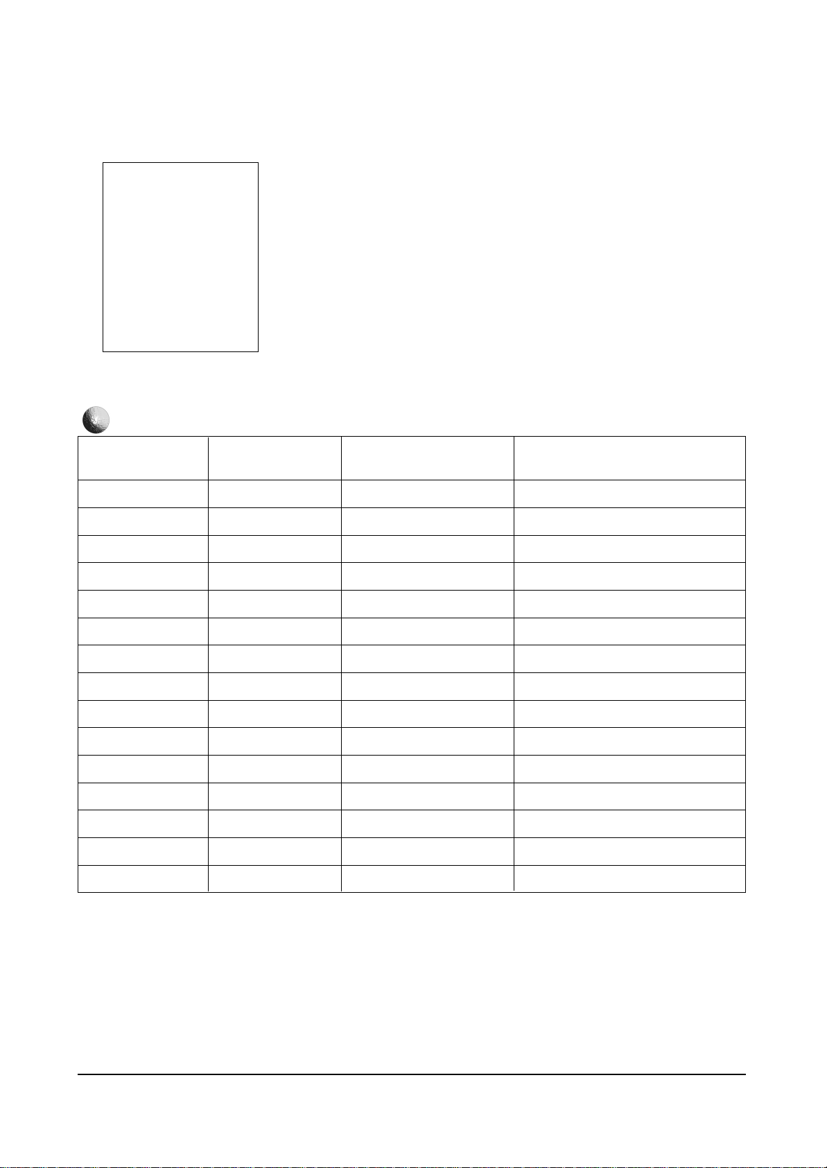
V Shift
V AMP
V Lin
V SC
V EHT
H AMP
Pin Phase
Pin AMP
Up Corner
Low Corner
H EHT
H Shift
V Angle
V BOW
H Sync Phase
0 ~ 255
0 ~ 255
0 ~ 255
0 ~ 255
0 ~ 255
0 ~ 255
0 ~ 255
0 ~ 255
0 ~ 255
0 ~ 255
0 ~ 255
0 ~ 127
0 ~ 255
0 ~ 255
0 ~ 255
4-4-2 CS MODEL
FUNCTION RANGE
INITIAL DATA
124
134
11
104
0
161
143
70
128
128
0
80
124
128
128
Service Mode
Deflection
Video Adjust1
Video Adjust2
NTSC OFFSET & CG
DW PIP & OTHERS
OPTION
RESET
DEFLECTION
REMARK
Page 10
Alignment and Adjustments
4-10 Samsung Electronics
VIDEO ADJUST1
0 ~ 63
0 ~ 63
0 ~ 63
0 ~ 63
0 ~ 63
0 ~ 63
0 ~ 63
0 ~ 15
0 ~ 15
0 ~ 15
0 ~ 15
0 ~ 15
0 ~ 15
0 ~ 15
0 ~ 15
0 ~ 8
FUNCTION RANGE
INITIAL DATA
31
31
31
31
31
31
31
7
15
7
3
7
15
2
12
7
REMARK
Red Cutoff
Green Cutoff
Blue Cutoff
Red Drive
Green Drive
Blue Drive
Sub Bright
Sub Contrast
Sub Color
Sut Tint
RYR
RYB
GYR
GYB
Gamma
P.YC Delay
FUNCTION RANGE
INITIAL DATA
VIDEO ADJUST2
REMARK
SUB Sharp
Sharp FO
Prev Over
LT 1
CT1
VM-Level
VM-Delay
DC-TRAN
D Picture
H Width
0 ~ 3
0 ~ 3
0 ~ 3
0 ~ 3
0 ~ 3
0 ~ 3
0 ~ 3
0 ~ 3
0 ~ 3
0 ~ 3
3
2
3
2
1
2
3
3
3
1
Page 11
Alignment and Adjustments
Samsung Electronics 4-11
FUNCTION RANGE
INITIAL DATA
VIDEO ADJUST2
REMARK
H Time Mask
ABL Mode
ABL TH
TTX Position
TTX Contrast
VSU
RGB Bright
RGB Contrast
Melody Volume
0 ~ 3
0 ~ 3
0 ~ 3
0 ~ 40
0 ~ 255
0 ~ 15
0 ~ 127
0 ~ 63
0 ~ 20
1
1
1
5
200
3
0
24
10
FUNCTION RANGE
INITIAL DATA
NTSC OFFSET & CG
REMARK
Offset V Shift
Offset V AMP
Offset H AMP
Offset H Shift
Cg R Contrast
Cg G Contrast
Cg B Contrast
Cg VAO PAL
Cg VAO NTSC
-64 ~ 63
-64 ~ 63
-64 ~ 63
-64 ~ 63
0 ~ 100
0 ~ 100
0 ~ 100
0 ~ 100
0 ~ 100
2
0
6
4
100
60
10
24
24
Page 12
Alignment and Adjustments
4-12 Samsung Electronics
PIP VSTR
PIP HSTR
PIP Contrast
DW 43 BCKPOS
DW 43 BCKWID
Cr offset1
Cb offset1
Cr offset2
Cb offset2
SDA9280 LPF
SDA9280 BPF
SDA9280 HPF
SDA9280
CORING/PHACOM
SDA9400 Y NR
SDA9400 C NR
0 ~ 15
0 ~ 15
0 ~ 63
0 ~ 255
0 ~ 255
0 ~ 15
0 ~ 15
0 ~ 15
0 ~ 15
0 ~ 7
0 ~ 15
0 ~ 15
0 ~ 7
0 ~ 15
0 ~ 15
FUNCTION RANGE
INITIAL DATA
VPC3230 0 X 0087
VPC3230 0 X 008A
VPC3230 fp 0 X 0053
SDA9280 0 X 09
SDA9280 0 X 0A
CXA2101 0 X 0F D7:D4
CXA2101 0 X 0F D3:D0
CXA2101 0 X 10 D7:D4
CXA2101 0 X 10 D7:D4
SDA9280 0 X 04 D6:D4
SDA9280 0 X 04 D3:D0
SDA9280 0 X 05 D3:D0
SDA9280 0 X 05 D6:D4
SDA9400 0 X 1E D7:D4
SDA9400 0 X 10 D3:D0
DW PIP & OTHERS
REMARK
ITEM
7
7
48
148
61
10
10
7
7
4
12
10
4
15
15
0 ~ 15
0 ~ 15
0 ~ 63
0 ~ 255
0 ~ 255
0 ~ 15
0 ~ 15
0 ~ 15
0 ~ 15
0 ~ 7
0 ~ 15
0 ~ 15
0 ~ 7
0 ~ 15
0 ~ 15
DOLBY
OFF
OFF
ON
ON
DOUBLE
ON
OPTION BYTE
SP47W3HF
SP43T6HF
SIM-816HC OPTION-BYTE
SP55W3HF REMARK
SOUND
WIDE
SCART1
PC
AUTO FM
PIP
HIGH DEVIATION
DOLBY
OFF
OFF
ON
ON
DOUBLE
ON
DOLBY
OFF
OFF
ON
ON
DOUBLE
ON
DOLBY <--> A2/NICAM <--> V-DOLBY
ON <--> OFF
ON <--> OFF
ON <--> OFF
ON <--> OFF
OFF <--> 1-TUNER <--> 2-TUNER <--> DOUBLE
ON <--> OFF
Page 13
Alignment and Adjustments
Samsung Electronics 4-13
4-4-3 W3 EU FACTORY DATA
VIDEO ADJUSTMENT
PAL-B/G
PAL-D/K/L
PAL-I
SECAM-B/G
SECAM-D/K/L
NTSC
PAL-AV
SECAM-AV
NTSC-AV
RGB
DVD
YC
SDA9280
SDA9280
SDA9280
SDA9280
SDA9280
-
SDA9280
SDA9280
SDA9280
SDA9280
SDA9280
SDA9280
ITEM CONTROL IC
DEFAULT VALUE
6 (0 ~15)
8 (0 ~15)
8 (0 ~15)
5 (0 ~15)
7 (0 ~15)
-
6 (0 ~15)
4 (0 ~15)
5 (0 ~15)
7 (0 ~15)
9 (0 ~15)
9 (0 ~15)
Y.C DELAY
NO
0
1
2
3
4
5
6
7
8
9
10
11
R Drive
B Drive
G Drive
Gamma
R Cutoff
B Cutoff
G Cutoff
Sub Contrast
Sub Bright
Sub Color
Sub Tint
V Peaking
TTX Contrast
TTX Bright
PIP Contrast
Not used
Cg R Contrast
Cg G Contrast
Cg B Contrast
CXA2101
CXA2101
CXA2101
CXA2101
CXA2101
CXA2101
CXA2101
CXA2101
CXA2101
CXA2101
CXA2101
VPC3230
CXA2101
CXA2101
VPC3230
-
CXA2101
CXA2101
CXA2101
ITEM CONTROL IC
DEFAULT VALUE
29 (0 ~ 63)
36 (0 ~ 63)
32 (0 ~ 63)
8 (0 ~ 15)
31 (0 ~ 63)
15 (0 ~ 63)
32 (0 ~ 63)
15 (0 ~ 63)
28 (0 ~ 63)
9 (0 ~ 63)
9 (0 ~ 63)
8 (0 ~ 63)
7 (0 ~ 63)
0 (0 ~ 63)
43 (0 ~ 63)
-
31 (0 ~ 63)
31 (0 ~ 63)
15 (0 ~ 63)
NO
0
1
2
3
4
5
6
7
8
9
10
11
12
13
14
15
16
17
18
Page 14
Alignment and Adjustments
4-14 Samsung Electronics
DEFIECTION NORMAL
(When a PAL signal is input)
P.V-Size
P.V-Sft
P. V - L i n
P.V-Corr
P.EW-Wht
P.EW-Pbl
P.H-Sft
P.EW-Tpz
P.Bow
P.Angle
P.EW-UpCr
P.EW-LoCr
P.Hor-EHT
P.Ver-EHT
P.Int.Vol.Ref
P.Hsync Delay
P.PIP H-Position
P.PIP V-Position
P.Not used
P.Not used
P.CG V-amp Offset
SDA9361
SDA9361
SDA9361
SDA9361
SDA9361
SDA9361
SDA9361
SDA9361
SDA9361
SDA9361
SDA9361
SDA9361
SDA9361
SDA9361
SDA9361
SDA9361
VPC3230
VPC3230
-
-
SDA9361
ITEM CONTROL IC
DEFAULT VALUE
-40 (-128 ~ 127)
-34 (-128 ~ 127)
0 (-128 ~ 127)
0 (-128 ~ 127)
44 (-128 ~ 127)
-27 (-128 ~ 127)
0 (-63 ~ 64)
0 (-128 ~ 127)
0 (-128 ~ 127)
0 (-128 ~ 127)
0 (-128 ~ 127)
0 (-128 ~ 127)
0 (0 ~ 255
0 (0 ~ 255)
0 (-16 ~ 15)
10 (-128 ~ 127)
7 (0 ~ 15)
7 (0 ~ 15)
-
-
30 (-128 ~ 127)
NO
0
1
2
3
4
5
6
7
8
9
10
11
12
13
14
15
16
17
18
19
20
DEFIECTION NORMAL
(When a NTSC signal is input)
N.V-Size
N.V-Sft
N.V-Lin
N.V-Corr
N.EW-Wht
N.EW-Pbl
N.H-Sft
N.EW-Tpz
N.Bow
N.Angle
N.EW-UpCr
N.EW-LoCr
N.Hor-EHT
N.Ver-EHT
N.Int.Vol.Ref
N.Hsync Delay
N.PIP H-Position
N.PIP V-Position
N.Not used
N.Not used
N.CG V-amp Offset
SDA9361
SDA9361
SDA9361
SDA9361
SDA9361
SDA9361
SDA9361
SDA9361
SDA9361
SDA9361
SDA9361
SDA9361
SDA9361
SDA9361
SDA9361
SDA9361
VPC3230
VPC3230
-
-
SDA9361
ITEM CONTROL IC
DEFAULT VALUE
-40 (-128 ~ 127)
-34 (-128 ~ 127)
0 (-128 ~ 127)
0 (-128 ~ 127)
44 (-128 ~ 127)
-27 (-128 ~ 127)
0 (-63 ~ 64)
0 (-128 ~ 127)
0 (-128 ~ 127)
0 (-128 ~ 127)
0 (-128 ~ 127)
0 (-128 ~ 127)
0 (0 ~ 255
0 (0 ~ 255)
0 (-16 ~ 15)
10 (-128 ~ 127)
7 (0 ~ 15)
7 (0 ~ 15)
-
-
30 (-128 ~ 127)
NO
0
1
2
3
4
5
6
7
8
9
10
11
12
13
14
15
16
17
18
19
20
Page 15
Alignment and Adjustments
Samsung Electronics 4-15
Limit Level
System
CLP-MSK
ABL-MODE
ABL-TH
DTV-SYNC
Cr-Offset1
Cb-Offset1
Cr-Offset2
Cb-Offset2
CTI-Level
R-Y/R
R-Y/B
G-Y/R
G-Y/B
LRGB2-Level
PABL-Level
BLK-Bottom
SUB-SHP
SUB-FO
PRE-OVER
LTI-Level
VM-Levle
VM-Delay
DC-TRAN
D-PIC
DCTI
BPF-LPF
HPF-Coing
Luminance signal edge enhancement setting
Signal frequency band switching
Switching of clamping pulse width in various ways
Switching of ABL mode
Adjustment of threshold voltage for ABL-IN input
DTV-Sync
For canceling the offset between CrCb of IN1and SEL IN systems
For canceling the offset between CrCb of IN1and SEL IN systems
For canceling the offset between CrCb of EXT systems
For canceling the offset between CrCb of EXT systems
Color difference signal edge enhancement setting
R-Y axis +(R-Y) component setting
R-Y axis -(B-Y) component setting
G-Y axis -(R-Y) component setting
G-Y axis -(B-Y) component setting
LRGB2 system picture level control
Setting of level detection DC at RGB-OUT of PEAK-ABL
RGB-OUT bottom limiter level control(valid when BLKSW = 1)
Sharpness center control
Sharpness f
o
setting
Presoot to overshoot ratio setting
Luminance signal edge enhancement setting
VM-OUT level control
VM-OUT phase control
Y system DC transmission ratio setting
Dynamic picture(black expansion)control
Digital Color Transition Improvement Control
Luminance Peaking Control
-Gain of band-pass filter -Gain of low-pass filter
Luminance Peaking Control
-Gain of high-pass filter -Gain of high-and band-pass filter
ITEM DESCRIPTION
DEFAULT VALUE
3 (0 ~ 3)
2 (0 ~ 3)
0 (0 ~ 3)
3 (0 ~ 3)
1 (0 ~ 3)
9 (0 ~ 255)
9 (0 ~ 15)
9 (0 ~ 15)
9 (0 ~ 15)
7 (0 ~ 15)
1 (0 ~ 3)
2 (0 ~ 15)
5 (0 ~ 15)
10 (0 ~ 15)
7 (0 ~ 15)
5 (0 ~ 15)
14 (0 ~ 15)
0 (0 ~ 15)
2 (0 ~ 3)
2 (0 ~ 3)
3 (0 ~ 3)
1 (0 ~ 3)
2 (0 ~ 3)
0 (0 ~ 3)
3 (0 ~ 3)
3 (0 ~ 3)
8 (0 ~ 255)
70 (0 ~ 255)
8 (0 ~ 255)
PICT. IMPROVE
CONTROL IC
CXA2101
CXA2101
CXA2101
CXA2101
CXA2101
CXA2101
CXA2101
CXA2101
CXA2101
CXA2101
CXA2101
CXA2101
CXA2101
CXA2101
CXA2101
CXA2101
CXA2101
CXA2101
CXA2101
CXA2101
CXA2101
CXA2101
CXA2101
CXA2101
CXA2101
CXA2101
SDA9280
SDA9280
SDA9280
0
1
2
3
4
5
6
7
8
9
10
11
12
13
14
15
16
17
18
19
20
21
22
23
24
25
26
27
28
NO
Page 16
Alignment and Adjustments
4-16 Samsung Electronics
NR-Luminance
NR-Chrominace
Luminance Noise Reduction
Chrominance Noise Reduction
ITEM DESCRIPTION
DEFAULT VALUE
8 (0 ~ 14)
6 (0 ~ 14)
PICT. IMPROVE
CONTROL IC
SDA9400
SDA9400
29
30
NO
System
Cr-Offset1
Cb-offset1
R-Y/R
R-Y/B
G-Y/R
G-Y/B
SUB-SHP
SUB-FO
PRE-OVER
LTI-Level
VM-Level
VM-Delay
DC-TRAN
D-PIC
Signal frequency band switching
For canceling the offset between CrCb of IN1 and SEL IN systems
For canceling the offset between CrCb of IN1 and SEL IN systems
R-Y axis +(R-Y) component setting
R-Y axis -(B-Y) component setting
G-Y axis -(R-Y) component setting
G-Y axis -(B-Y) component setting
Sharpness center control
Sharpness f
o
setting
Preshoot to overshoot ratio setting
Luminance signal edge enhancement setting
VM-OUT level control
VM-OUT phase control
Y system DC transmission ratio setting
Dynamic picture(black expansion)control
ITEM DESCRIPTION
DEFAULT VALUE
2 (0 ~ 3)
9 (0 ~ 15)
9 (0 ~ 15)
2 (0 ~ 15)
5 (0 ~ 15)
10 (0 ~ 15)
7 (0 ~ 15)
2 (0 ~ 3)
3 (0 ~ 3)
3 (0 ~ 3)
1 (0 ~ 3)
2 (0 ~ 3)
0 (0 ~ 3)
2 (0 ~ 3)
3 (0 ~ 3)
PICT. IMPROVE. VGA(NOT USED)
CONTROL IC
CXA2101
CXA2101
CXA2101
CXA2101
CXA2101
CXA2101
CXA2101
CXA2101
CXA2101
CXA2101
CXA2101
CXA2101
CXA2101
CXA2101
CXA2101
0
1
2
3
4
5
6
7
8
9
10
11
12
13
14
NO
Page 17

Alignment and Adjustments
Samsung Electronics 4-17
Cr-Offset1
Cb-offset1
R-Y/R
R-Y/B
G-Y/R
G-Y/B
For canceling the offset between CrCb of IN1 and SEL IN systems
For canceling the offset between CrCb of IN1 and SEL IN systems
R-Y axis +(R-Y) component setting
R-Y axis -(B-Y) component setting
G-Y axis -(R-Y) component setting
G-Y axis -(B-Y) component setting
ITEM DESCRIPTION
DEFAULT VALUE
7 (0 ~ 15)
11 (0 ~ 15)
3 (0 ~ 15)
7 (0 ~ 15)
10 (0 ~ 15)
2 (0 ~ 15)
PICT. IMPROVE. SECAM
CONTROL IC
CXA2101
CXA2101
CXA2101
CXA2101
CXA2101
CXA2101
0
1
2
3
4
5
NO
Cr-Offset1
Cb-offset1
DCT1
R-Y/R
R-Y/B
G-Y/R
G-Y/B
VM-Level
VM-Delay
V-PEAKING
BPF-LPF
HPF-Coring
For canceling the offset between CrCb of IN1 and SEL IN systems
For canceling the offset between CrCb of IN1 and SEL IN systems
Digital Color Transition Improvement Control
R-Y axis +(R-Y) component setting
R-Y axis -(B-Y) component setting
G-Y axis -(R-Y) component setting
G-Y axis -(B-Y) component setting
VM-OUT level control
VM-OUT phase control
Vertical Peaking
Luminance Peaking Control
-Gain of band-pass filter -Gain of low-pass filter
Luminance Peaking Control
-Gain of band-pass filter -Gain of low-pass filter
ITEM DESCRIPTION
DEFAULT VALUE
9 (0 ~ 15)
9 (0 ~ 15)
0 (0 ~ 255)
2 (0 ~ 15)
5 (0 ~ 15)
10 (0 ~ 15)
7 (0 ~ 15)
0 (0 ~ 3)
0 (0 ~ 3)
0 (0 ~ 12)
72 (0 ~ 255)
10 (0 ~ 255)
PICT. IMPROVE. RGB
CONTROL IC
CXA2101
CXA2101
SDA9280
CXA2101
CXA2101
CXA2101
CXA2101
CXA2101
CXA2101
VPC3230
SDA9280
SDA9280
0
1
2
3
4
5
6
7
8
9
10
11
NO
Page 18

Alignment and Adjustments
4-18 Samsung Electronics
Cr-Offset1
Cb-offset1
DCT1
R-Y/R
R-Y/B
G-Y/R
G-Y/B
VM-Level
VM-Delay
V-PEAKING
BPF-LPF
HPF-Coring
For canceling the offset between CrCb of IN1 and SEL IN systems
For canceling the offset between CrCb of IN1 and SEL IN systems
Digital Color Transition Improvement Control
R-Y axis +(R-Y) component setting
R-Y axis -(B-Y) component setting
G-Y axis -(R-Y) component setting
G-Y axis -(B-Y) component setting
VM-OUT level control
VM-OUT phase control
Vertical Peaking
Luminance Peaking Control
-Gain of band-pass filter -Gain of low-pass filter
Luminance Peaking Control
-Gain of high-pass filter -Gain of high-and band-pass filter
ITEM DESCRIPTION
DEFAULT VALUE
9 (0 ~ 15)
9 (0 ~ 15)
0 (0 ~ 255)
2 (0 ~ 15)
5 (0 ~ 15)
10 (0 ~ 15)
7 (0 ~ 15)
1 (0 ~ 3)
0 (0 ~ 3)
0 (0 ~ 12)
72 (0 ~ 255)
10 (0 ~ 255)
PICT. IMPROVE. DVD
CONTROL IC
CXA2101
CXA2101
SDA9280
CXA2101
CXA2101
CXA2101
CXA2101
CXA2101
CXA2101
VPC3230
SDA9280
SDA9280
0
1
2
3
4
5
6
7
8
9
10
11
NO
Cr-Offset1
Cb-offset1
DCT1
R-Y/R
R-Y/B
G-Y/R
G-Y/B
VM-Level
VM-Delay
V-PEAKING
BPF-LPF
HPF-Coring
For canceling the offset between CrCb of IN1 and SEL IN systems
For canceling the offset between CrCb of IN1 and SEL IN systems
Digital Color Transition Improvement Control
R-Y axis +(R-Y) component setting
R-Y axis -(B-Y) component setting
G-Y axis -(R-Y) component setting
G-Y axis -(B-Y) component setting
VM-OUT level control
VM-OUT phase control
Vertical Peaking
Luminance Peaking Control
-Gain of band-pass filter -Gain of low-pass filter
Luminance Peaking Control
-Gain of high-pass filter -Gain of high-and band-pass filter
ITEM DESCRIPTION
DEFAULT VALUE
9 (0 ~ 15)
9 (0 ~ 15)
0 (0 ~ 255)
2 (0 ~ 15)
5 (0 ~ 15)
10 (0 ~ 15)
7 (0 ~ 15)
1 (0 ~ 3)
0 (0 ~ 3)
0 (0 ~ 12)
72 (0 ~ 255)
10 (0 ~ 255)
PICT. IMPROVE. YC
CONTROL IC
CXA2101
CXA2101
SDA9280
CXA2101
CXA2101
CXA2101
CXA2101
CXA2101
CXA2101
VPC3230
SDA9280
SDA9280
0
1
2
3
4
5
6
7
8
9
10
11
NO
Page 19

Alignment and Adjustments
Samsung Electronics 4-19
STD Bright
STD Contrast
STC Color
STD Sharpness
STD Tint
STD Colortone
Sports Bright
Sports Contrast
Sports Color
Sports Sharpness
Sports Tint
Sports Colortone
Mild Bright
Mild Contrast
Mild Color
Mild Sharpness
Mild Tint
Mild Colortone
Natural Bright
Natural Contrast
Natural Color
Natural Sharpness
Natural Tint
Natural Colortone
VGA Bright
VGA Contrast
RGB Color
RGB Color_L
RGB Tint
RGB Bri_Cont
Standard Mode Brightness
Standard Mode Contrast
Standard Mode Color
Standard Mode Sharpness
Standard Mode Tint
Standard Mode Colortone
Sports Mode Brightness
Sports Mode Contrast
Sports Mode Color
Sports Mode Sharpness
Sports Mode Tint
Sports Mode Colortone
Mild Mode Brightness
Mild Mode Contrast
Mild Mode Color
Mild Mode Sharpness
Mild Mode Tint
Mild Mode Colortone
Natural Mode Brightness
Natural Mode Contrast
Natural Mode Color
Natural Mode Sharpness
Natural Mode Tint
Natural Mode Colortone
Not used
Not used
RGB Mode Color
RGB Mode Color
RGB Mode Tint
RGB Mode Brightness, Contrast
ITEM DESCRIPTION
DEFAULT VALUE
32 (0 ~ 63)
42 (0 ~ 63)
32 (0 ~ 63)
32 (0 ~ 63)
0 (-31 ~ 31)
0 (0 ~ 4)
32 (0 ~ 63)
51 (0 ~ 63)
32 (0 ~ 63)
38 (0 ~ 63)
0 (-31 ~ 31)
3 (0 ~ 4)
35 (0 ~ 63)
32 (0 ~ 63)
32 (0 ~ 63)
28 (0 ~ 63)
0 (-31 ~ 31)
1 (0 ~ 4)
28 (0 ~ 63)
63 (0 ~ 63)
32 (0 ~ 63)
45 (0 ~ 63)
0 (-31 ~ 31)
3 (0 ~ 4)
32 (0 ~ 63)
32 (0 ~ 63)
5 (0 ~ 255)
209 (0 ~ 255)
0 (0 ~ 255)
27 90 ~ 255)
P.STD CHANGE
CONTROL IC
CXA2101
CXA2101
CXA2101
CXA2101
VPC3230
CXA2101
CXA2101
CXA2101
CXA2101
CXA2101
VPC3230
CXA2101
CXA2101
CXA2101
CXA2101
CXA2101
VPC230
CXA2101
CXA2101
CXA2101
CXA2101
CXA2101
VPC3230
CXA2101
CXA2101
CXA2101
VPC3230
VPC3230
VPC3230
VPC3230
0
1
2
3
4
5
6
7
8
9
10
11
12
13
14
15
16
17
18
19
20
21
22
23
24
25
26
27
28
29
NO
Page 20

Alignment and Adjustments
4-20 Samsung Electronics
RGB Bri-Cont_L
FB Gain
Slicer Level
RGB Mode Brightness, Contrast
Fast Blanking Signal Gain Control
Slicer Level Control
ITEM DESCRIPTION
DEFAULT VALUE
68 (0 ~ 255)
144 (0 ~ 255)
15 (0 ~ 255)
P.STD CHANGE
CONTROL IC
VPC3230
VPC3230
VPC3230
30
31
32
NO
Side Panel Pos.
Side Panel Width
Side Panel Level
Side Panel B-Y
Side Panel R-Y
Side Panel Position Control
Side Panel Width Control
Side Panel Luminance Control
Side Panel Chrominance Control
Side Panel Chrominance Control
ITEM DESCRIPTION
DEFAULT VALUE
153 (0 ~ 255)
69 (0 ~ 255)
7 (0 ~ 15)
0 (0 ~ 15)
0 (0 ~ 15)
SIDE PANEL ADJUST
CONTROL IC
SDA9280
SDA9280
SDA9280
SDA9280
SDA9280
0
1
2
3
4
NO
Page 21

Alignment and Adjustments
Samsung Electronics 4-21
4-5 Screen Change (When adjusting I2C Bus Geometric items)
1 V SHIFT
2 V LINEARITY
3 H SIZE
6 V SIZE
7 V - S - CORRECTION
8
PIN PHASE
4
PIN AMP
5 V ANGLE
9 H SHIFT
10 V BOW
Page 22

Alignment and Adjustments
4-22 Samsung Electronics
4-6 Other Adjustments
4-6-1 Screen Adjustment
1. Warm up the TV for at least 30 minutes.
2. Turn to the Video Mode (No Signal) using a
remote-control.
3. Connect an oscilloscope to RK,GK,BK.
4. Adjust the VR (VR501, VR531, VR561) screen
so that RK, GK, BK pulse is 20Vp-p each.
(Turn the R,G,B VR screen fully
counterclockwise in the area of each flyback
line.)
4-6-2 White Balance Adjustment
1. Select the “STANDARD” video mode.
2. Input 100% white pattern.
3. In the stand-by mode, press the remote-control
keys in the following sequence:
Displsy → Menu → Mute → Power ON
4. Warm up the TV for at least 30 minutes.
5. Input a 10-step signal.
6. R-cut off, B-cut off, and G-cut off by pressing
the Volume +/- keys.
7. Adjust the low light with viewing the dark
side of the screen.
8. Select R-drive, G-drive, and B-drive by
pressing the Volume +/- keys.
9. Adjust the high light with viewing the light
side of the screen.
10. If necessary, redo adjustments 6~9.
11. Press the Menu key to exit.
4-6-3 Sub-Brightness Adjustment
1. Input a sub-brightness adjustment signal.
(TOSHIBA PATTERN)
2. In the stand-by mode, press the remote-control
keys in the following sequence :
Displsy → Menu → Mute → Power ON
3. Select SBT by pressing the Volume +/- keys.
4. Adjust so that the 63 step on the right side of
the screen is not seen (Use the Volume +/keys).
5. Press the Menu key to exit.
4-6-4 High Voltage (29KV) Check
PRECAUTION
1. Input a lion head pattern.
2. Select “STANDARD” video mode.
3. Warm up the TV for at least 10 minutes.
4. Use a 1000:1 probe.
ADJUSTMENT
1. Connect the (+) terminal of the 1000:1 probe to
the high voltage distributor and the (-)
terminal to GND (located on the deflection
board).
2. Adjust RR471S (located on the deflection
board) so that the digital meter indicates
DC 29V ± 0.1V.
4-6-5 F.S. (Fail Safe) Adjustment
Note : The finished product has a well-mounted
VR (RR402S).
If necessary, do the F.S. adjustments in the
following sequence.
1. Use a digital multimeter.
2. Connect the digital multimeter to the JIG pin
(DZ482S) terminals
3. Adjust VR (RR402S) so that the voltage
becomes 2.25V.
4. After the adjustments are complete, be sure to
mount VR (RR402S) correctly.
Page 23

Alignment and Adjustments
Samsung Electronics 4-23
4-6-6 F.S. (Fail Safe) Circuit Check
Note : The F.S. Circuit check must be performed
after servicing.
1. Turn on the TV.
2. Select the “STANDARD” video mode.
3. Short F/S Test point (located on the SUB PCB).
Then, both sound and picture disappear.
(Note: Even if the shorted terminals are
removed, both sound and
picture do not appear. This proves the F.S.
circuit is working. )
4. To restore both sound and picture, turn off the
TV and reset it after about 30 seconds.
4-6-7 Static Focus Adjustment
PRECAUTION
1. Select the “STANDARD” video mode.
2. Input a crosshatch pattern.
3. Cover the lenses that are not being adjusted.
4. Connect a convergence jig and read data.
5. Adjust the lens for best focus.
(See Fig, 4-1, next page)
STATIC FOCUS (CONTINUED)
Vary the focus pack VR (Red, Blue) on the
front cabinet. Adjust the TV for best possible
focus around the center of the crosshatch
pattern, without losing overall screen balance.
Figure Crosshatch Pattern
Examine these points together.
4-6-8 Lens Focus Adjustment
PRECAUTIONS
1. Do this adjustment after the static focus
adjustment and the tilt adjustment.
2. Select the “STANDARD” video mode.
(Contrast:100, Brightness:50)
3. Input a crosshatch pattern.
ADJUSTMENT
1. Loosen the lens screws.
2. Cover the two lenses that are not being
adjusted.
3. Adjust the lens, observing the color aberration
vertically and horizontally within 3 blocks of
the center of the crosshatch pattern.
4. When the lens is turned clockwise, the color
aberration will change as follows:
Lens Color Aberration Change
R Orange - Crimson
G Blue - Red
B Purple - Green
5. Green lens adjustment:
Set the lens at the point where Blue just
changes to Red. If the color aberration is
irregular throughout the picture screen, adjust
the lens to show Red color aberration
(approximately 1~3 mm area) within a 3-block
grid around the horizontal center-line. If the
color aberration is irregular, adjust the lens as
shown in the diagram below. (Accurate
alignment of Green is important for overall
color quality.)
6. Red lens adjustment
Set the Red lens at the point where Orange
becomes Crimson.
7. Blue lens adjustment
Set the Blue lens at the point where Purple
becomes Green.
P
L1
L2
RED ABERRATION
BLUE ABERRATION
L1, L2 < P
_
Fig. 4-1 Crosshatch Pattern.
Fig. 4-2 Color Aberration
Examine these points together
Page 24

Alignment and Adjustments
4-24 Samsung Electronics
4-6-9 Horizontal Dynamic Focus Adjustment
PRECAUTION
1. Input a crosshatch pattern.
2. Select the “STANDARD” video mode.
3. Warm up the set for at least 10 minutes.
ADJUSTMENT
1. Cover the Red and Blue lenses.
2. Use a digital multimeter.
3. Connect the '+' terminal of digital multimeter
to D-Focus and the '-' terminal to GND.
4. Adjust L434 located on the sub PCB so that
the digital multimeter indicates
AC690 20Vp-p.(WIDE AC600 20Vp-p)
5. Balance the left and right sides of the dynamic
focus lines.
Page 25

Alignment and Adjustments
Samsung Electronics 4-25
4-7 SCREEN-JIG
4-7-1 43T6 Normal Mode
4-7-2 54T6 Normal Mode
Normal 4:3 Mode
Screen Size : X 873, Y 655 (X:378=9*2+ 30*12, Y:440=28*2+ 64*6)
20.79mm 69.29mm
41.68mm
95.27mm
41.68mm
Norm al 4:3 mode
Screen Size : X 1098.4, Y 827.4 (X:378=9*2+ 30*12, Y:440=28*2+ 64*6)
20.79mm
52.65mm
120.35mm
52.65mm
26.15mm 87.17mm
26.15mm
Page 26

Alignment and Adjustments
4-26 Samsung Electronics
4-7-3 47W3 Normal Mode
4-7-4 55W3 Normal Mode
Norm al 4:3 mode
Screen Size : X 1045, Y 588 (X:378=9*2+ 30*12, Y:440=28*2+ 64*6)
37.42mm
85.53mm
37.42mm
24.88mm 82.94mm
24.88mm
Norm al 4:3 mode
29.17mm 97.22mm
43.65mm
99.78mm
43.65mm
Screen Size : X 1225, Y 686 (X:378=9*2+ 30*12, Y:440=28*2+ 64*6)
29.17mm
Page 27

Alignment and Adjustments
Samsung Electronics 4-27
4-7-5 65W3 Normal Mode
Nor m al mo de
34.33mm 114.44mm
53.33mm
121.89mm
53.33mm
Screen Size : X 1442, Y 838 (X:378=9*2+ 30*12, Y:440=28*2+ 64*6)
34.33mm
Page 28

4-28 Samsung Electronics
Alignment and Adjustments
4-8 Remote Control for Servicing
4-8-1 WESTERN EUROPE
Power
Page 29

Alignment and Adjustments
Samsung Electronics 4-29
4-8-2 CHINA
Power
Page 30

Alignment and Adjustments
4-30 Samsung Electronics
4-8-3 KEY Function
1. R-SELECT
Press to select RED color.
2. G-SELECT
Press to select GREEN color.
3. B-SELECT
Press to select BLUE color.
4. R-MUTE
Press to mute RED color.
5. G-MUTE
Press to mute GREEN color.
6. B-MUTE
Press to mute BLUE color.
7. CANCEL KEY
Press to revert to the previous data during the Convergence
Adjustment.
8. TEST/NORMAL
Press to check TV mode in the Convergence Mode.
9. LINE SHIFT
Press to move a line up/down or left/right.
10. FACTORY DATA SELECT BUTTON
Press to call the factory default values.
11. H/V DIRECTION SELECT BUTTON
Press to switch the cursor direction horizontally or vertically.
12. SAVE BUTTON
After the Convergence Adjustments are completed, press to save data.
13 EXIT BUTTON
After the Convergence adjustments are completed, press to exit to TV mode.
Page 31

Alignment and Adjustments
Samsung Electronics 4-31
14. MOVE CURSOR FORWARD
Press to move the cursor right or down.
15. MOVE CURSOR REVERSE JOYSTICK(Option )
Press to move the cursor left or up.
16. CONVERGENCE PICTURE MOVE BUTTON
17. CONVERGENCE MOVE BUTTON
Press to move the convergence left ( ) or right ( ) .
18. CONVERGENCE DATA ZERO BUTTON
Press to zero the convergence correction data.
19. INITIAL DATA SET BUTTON
20. Data Shift Button Press to transmit data(PAL Mode/NTSC Mode)
Inch (Type)
43” (43T6)
54” (54T6)
62” (62T6)
47”(47W3)
55”(55W3)
65”(65W3)
Model Name
Representative
Model
SP43T6
SP54T6
SP62T6
SP47W3
SP55W3
SP65W3
Basic Data
Number after entring
the Cg-Mode
5-436 (Press in regular order)
5-546 (Press in regular order)
5-626 (Press in regular order)
5-479 (Press in regular order)
5-559 (Press in regular order)
5-659 (Press in regular order)
Screen Display
Discription
White Oval on the background
(white circle)
White Oval on the background
(white border)
White Oval on the background
(white circle)
White Oval on the background
(white border)
Changes when applying Almighty-Cg, Module (How to extract the basic Cg Data)
Page 32

Alignment and Adjustments
4-32 Samsung Electronics
4-9 Convergence Adjustment
Special Notes
✏ A sensor is attached on the center of each side of the Convergence Mode pattern
(see figure below). The sensors are required for normal Perfect Focus function.
✏ Use a screen jig to do the convergence adjustments correctly (Especially, perform
correct convergence adjustments on the center of each side where a sensor is located.)
✏ Do the convergence adjustments correctly. Otherwise, any Perfect Focus error can
happen.
1. Warm up the TV for a least 30 minutes.
2. Input an PAL Signal.(Use an antenna or AV source.)
Make sure that deflection yoke are properly adjusted so that the center of
Green, Red, Blue pattern is aligned on the center of screen jig.
3. Enter the Convergence Mode by Pressing the remote control keys in the following sequence:
If OSD displayed as shown in figure below, press the key to exit.
Then, redo step 3 to enter the Convergence Mode.
After entering the Convergence Mode, Stand by for about five seconds
before doing the adjustments.
Page 33

Alignment and Adjustments
Samsung Electronics 4-33
Page 34

Alignment and Adjustments
4-34 Samsung Electronics
Page 35

Samsung Electronics 4-35
Page 36

Alignment and Adjustments
4-36 Samsung Electronics
Page 37

Alignment and Adjustments
Samsung Electronics 4-37
4-10 MICOM and Pins Voltage
4-10-1 Pin Layout(CW)
P3.1
D1
P3.0
D2
P1.6
D3
NC
P1.5
P1.4
P1.3
P1.2
P1.1
P1.0
VSS
VDD
XTAL2
XTAL1
RST
ALE
A16
PROTECT
ST-BY LED1
TIMER LED2
POWER
POWER2
TXD
VSS
VDD
XTAL2
XTAL1
RESET
A16
CENTER RESET
RXD
IR
P3.3
P3.2
M3L ENABLE
M3L DATA
M3L CLK
P3.7
P3.6
P3.5
P3.4
VDDA
A3
A3
VDDA
SUB AFT
VSSA
P2.0
VSSA
MAIN AFT
KEYS2
P2.2
P2.1
BUS-STOP
KEYS1
P0.7
P2.3
AMP MUTE
P0.5
P0.6
64 63 62 61 60 59 58 57 56 55 54 53 52 51 50 49
P0.4 WP
48
P0.3 SCL2
47
P0.2 SDA2
46
P0.1 SDA1
45
P0.0 SCL1
44
P4.1 A18
43
P4.0 A17
42
VDD VDDD
41
SDA30C264
40
39
38
37
36
35
34
33
VSS VSSD
A2 A2
A1 A1
A0 A0
D3 D3
D2 D2
D4 D4
D1 D1
17 18 19 20 21 22 23 24 25 26 27 28 29 30 31 32
D5
D0
D6
D7
A10
A4
A11
A5
A6
A8
A7
A13
A12
A14
A15
D5
D0
D6
D7
A10
A4
A11
A5
A6
A8
A7
A13
A12
A14
A15
Page 38

Alignment and Adjustments
4-38 Samsung Electronics
4-10-2 MICOM Pins(CW)
1D1 D1
2D2 D2
3D3 D3
4 PROTECT PROTECT
5 ST-BY LED ST-BY LED
6 TIMER LED TIMER LED
7 POWER POWER
8 POWER2 POWER2
9 TXD TXD
10 VSS VSS
11 VDD VDD
12 XTAL2 XTAL2
13 XTAL1 XTAL1
14 RESET RESET
15 NC NC
16 A16 A16
17 A15 A15
18 A14 A14
19 A12 A12
20 A13 A13
21 A7 A7
22 A8 A8
23 A6 A6
24 A9 A9
25 A5 A5
26 A11 A11
PIN NO. ITEM FUNCTION OUT VOLT
Page 39

Alignment and Adjustments
Samsung Electronics 4-39
27 A4 A4
28 D10 D10
29 D7 D7
30 D6 D6
31 D0 D0
32 D5 D5
33 D1 D1
34 D4 D4
35 D2 D2
36 D3 D3
37 A0 A0
38 A1 A1
39 A2 A2
40 VSS VSS
41 VDD VDD
42 A17 A17
43 A18 A18
44 SCL1 SCL1
45 SDA1 SDA1
46 SDA2 SDA2
47 SCL2 SCL2
48 WP WP
49 AMP-MUTE AMP-MUTE
50 CENTER-MUTE CENTER-MUTE
51 BUS-STOP BUS-STOP
52 KEY1 KEY1
PIN NO. ITEM FUNCTION OUT VOLT
Page 40

Alignment and Adjustments
4-40 Samsung Electronics
53 KEY2 KEY2
54 MAIN-AFT MAIN-AFT
55 SUB-AFT SUB-AFT
56 VSS VSS
57 A3 A3
58 VDD VDD
59 M3L CLK M3L CLK
60 M3L DAT M3L DATA
61 M3L ENABLE M3L ENABLE
62 NC NC
63 RXD RXD
64 IR IR
PIN NO. ITEM FUNCTION OUT VOLT
Page 41

Alignment and Adjustments
Samsung Electronics 4-41
4-10-3 Pin Layout(CS)
W.P
SDA2
SCL2
BUS-STOP
SDA1
SCL1
S-RESET
V-MUTE
VDD 2.5V
GND
VDD 3.3V
CVBS IN
VDD 2.5V
GND
AFT
SUB-AFT
KEY2
KEY1
H-BLK
V-BLK
KEY3
PROTECT
SCONT1
IR-IN
D3
TIMER LED
1
2
3
4
5
6
7
8
9
10
11
12
13
14
15
16
17
18
19
20
21
22
23
24
25
26
S
D
A
5
5
5
X
52
SCONT 0
51
POWER 2
50
POWER
49
S-MUTE
48
DVD-CTL
47
LENTER SPK-MUTE
46
DTV-ID
45
DVD-ID
44
VDD 3.3V
43
GND
42
VDD 2.5V
41
OSD F/B
40
OSD B
39
OSD G
38
OSD R
37
VDD 2.5V
36
GND
35
X-OUT
34
X-IN
33
RESET
32
D1
31
D2
VDD 3.3V
30
GND
29
RTXD
28
ST-BY LED
27
Page 42

Alignment and Adjustments
4-42 Samsung Electronics
4-10-4 MICOM Pins(CS)
1W.P
2 SDA2
3 SCL2-
4 BUS-STOP I2BUS STOP
5 SDA-1 DATA BUS LINE
6 SCL-1 CLOCK BUS LINE
7 S-RESET SOUND RESET
8 V-MUTE VIDEO SIGNAL MUTE
9 VDD VDD 2.5V
10 GND GND
11 VCC VCC 3.3V
12 CVBS CVBS IN
13 VDD VDD 2.5V
14 GND GND
15 MAIN-AFT MAIN TUNER AFT
16 SUB-AFT SUB AUTO FINE TURNING CONTROL
17 KEY2 KEY SCAN 2
18 KEY1 KEY SCAN 1
19 HSYNC HORIZONTAL SYNC INPUT
20 VSYNC VERTICAL SYNC INPUT
21 KEY3 KEY SCAN 3
22 PROTECT PROTECT PORT
23 S-CONTO SOUND MODE SELECT
24 IR IN REMOCON INPUT
25 D3 CONVERGENCE D3
26 TIMER-LED TIMER LED
PIN NO. ITEM FUNCTION OUT VOLT
Page 43

Alignment and Adjustments
Samsung Electronics 4-43
27 ST-BY-LEDD LED
28 RXD -
29 GND GND
30 VDD VDD 3.3V
31 D2 DATA BUS LINE
32 D1 CLOCK BUS LINE
33 /RESET RESET
34 XTAL1 XTAL1
35 XTAL2 XTAL2
36 GND GND
37 VDD VDD 2.5V
38 OSD R ON SCREEN DISPLAY RED OUTPUT
39 OSD G ON SCREEN DISPLAY GREEN OUTPUT
40 OSD B ON SCREEN DISPLAY BLUE OUTPUT
41 OSD F-B OSD BLAKING SIGNAL OUTPUT
42 VDD VDD 2.5V
43 GND GND
44 VDD VDD 3.3V
45 DVD-IDENT DVD-IDENT
46 DTV-INENT DTV-IDENT
47 CENTER SPK MUTE
48 MODE SELECT DVD MODE SELECT(480i/480p)
49 AMP-MUTE MAIN AMP MUTE
50 POWER POWERR ON/OFF RELAY CONTROL
51
52 S-CONTO SOUND MODE SELECT
PIN NO. ITEM FUNCTION OUT VOLT
Page 44

Alignment and Adjustments
4-44 Samsung Electronics
4-10-5 Proscan Module (CS)
1 Pr/R Pr/R INPUT 2.0V
2 Y/G Y/G INPUT 2.0V
3 Pb/B Pb/B INPUT 2.0V
4 FB FAST BLANKING INPUT 0.25V
5 GND GND -
6 HC 5V INPUT -
7 VS1 VS1 INPUT -
8 GND GND -
9 SDA SERIAL DATA LINE 4.7V
10 SCL SERIAL CLOCK LINE 4.8V
11 5V 5V 5V
12 27M OPTION -
13 GND GND GND
14 5V- 5V- 5V-
15 H-OUT HORIZENTAL-OUT N.C
16 V-OUT VERTICAL-OUT N.C
17 SCP -
18 EW EAST WEST OUT 2.2V
19 V-BLK V-BLANKING -
20 ABL ABL INPUT 2.15V
21 AD- VERTICAL DRIVE(-VOLTAGE) 2.95V
22 AD+ VERTICAL DRIVE(+VOLTAGE) 2.90V
23 H-BLK H-BLANKING INPUT -
24 HD H-DRIVE OUT 1.6V
25 GND GND GND
26 PIP-RF -
27 PIP-C -
28 PIP-V/Y -
29 GND GND GND
30 CVBS-Y -
PIN NO. ITEM FUNCTION OUT VOLT
Page 45

Alignment and Adjustments
Samsung Electronics 4-45
31 CHR CHROMA -
32 GND GND GND
33 PC-R N.C -
34 PC-G N.C -
35 PC-B N.C -
36 PC-H GND GND
37 PC-V OSD-R INPUT -
38 GND OSD-G INPUT -
39 OSD-R OSD-B INPUT -
40 OSD-G BLANK(MICOM OUT) -
41 OSD-B HALF TONE INPUT -
42 YS/YM VIDEO MUTE (V-CHIP ON) 4.72V
43 YS/YM GND GND
44 GND 9V 9V
45 9V D-Pr INPUT -
46 HD-Pr D-Y INPUT -
47 HD-Y D-Pb INPUT -
48 HD-Pb N.C -
49 GND GND GND
50 R-OUT R-OUT -
51 G-OUT G-OUT -
52 B-OUT B-OUT -
53 GND GND GND
54 IK IK OUT 3.65V
55 GND SPOT OUT -
56 GND GND GND
57 VM-Y VM-Y OUT 5.42V
58 YD N.C -
59 GND GND GND
60 CG-SYND CG-SYNC INPUT -
PIN NO. ITEM FUNCTION OUT VOLT
Page 46

Alignment and Adjustments
4-46 Samsung Electronics
61 CG-B CG-B INPUT -
62 CG-G CG-G INPUT -
63 CG-R CG-R INPUT -
64 GND GND GND
PIN NO. ITEM FUNCTION OUT VOLT
Page 47

Alignment and Adjustments
Samsung Electronics 4-47
4-10-6 Sound Module
1 GND GND GND
2 GND GND GND
3 GND GND GND
4 S-RESET SOUND RESET -
5 MAIN-L MAIN LEFT OUT -
6 GND GND GND
7 GND GND GND
85V 5V 5V
9 MAIN-R MAIN RIGHT OUT -
10 GND GND GND
11 GND GND GND
12 GND GND GND
13 8V 8V 8V
14 SCL-1 SERIAL CLOCK LINE -
15 GND GND GND
16 SDA-1 SERIAL DATA LINE -
17 CENTER CENTER OUT -
18 GND GND GND
19 GND GNAD GND
20 12V 12V 12V
21 SURROUND SURROUND OUT -
22 GND GND GND
23 GND GND GND
24 S-F1 S-F1(ANT1) -
25 GND GND GND
26 GND GND GND
27 AV4-L-IN AV4 LEFT INPUT -
28 A-MONO-IN A-MONO INPUT -
29 GND GND GND
30 GND GND GND
PIN NO. ITEM FUNCTION OUT VOLT
Page 48

Alignment and Adjustments
4-48 Samsung Electronics
31 AV4-R-IN AV4 RIGHT INPUT -
32 S-F2 S-F2(ANT2) -
33 GND GND GND
34 GND GND GND
35 GND GND GND
36 GND GND GND
37 EXT-L-IN EXTERNAL LEFT INPUT -
38 H-PHONE-L HEADPHONE LEFT OUT -
39 GND GND GND
40 GND GND GND
41 EXT-R-IN EXTERNAL RIGHT INPUT -
42 H-PHONE-R HEADPHONE RIGHT OUT -
43 GND GND GND
44 GND GND GND
45 GND GND GND
46 GND GND GND
47 AV2-L-IN AV2 LEFT INPUT -
48 MONITOR-L MONITOR OUT -
49 GND GND GND
50 GND GND GND
51 AV2-R-IN AV2 RIGHT INPUT -
52 MONITOR-R MONITOR OUT -
53 GND GND GND
54 GND GND GND
55 GND GND GND
56 GND GND GND
57 AV1-L-IN AV1 LEFT INPUT -
58 AV1-L-OUT AV1 LEFT OUTPUT -
59 GND GND GND
60 GND GND GND
PIN NO. ITEM FUNCTION OUT VOLT
Page 49

Alignment and Adjustments
Samsung Electronics 4-49
61 AV1-R-IN AV1 RIGHT INPUT -
62 AV1-R-OUT AV1 RIGHT OUT -
63 GND GND GND
64 GND GND GND
PIN NO. ITEM FUNCTION OUT VOLT
Page 50

Alignment and Adjustments
4-50 Samsung Electronics
4-10-7 CONV-Module
16V 6V 6V
2 GND GND GND
3 FOCUS N.C -
4 GND GND GND
5 D2 SDA -
6 D1 SCL -
7 GND GND GND
8 C-SYNC C-SYNC OUT 4.41V
9 R WHEN TEST PATTERN R OUT -
10 TEST-Y/G WHEN TEST PATTERN G OUT -
11 B WHEN TEST PATTERN B OUT -
12 D3 D3/NT-PAL SEL 0.2V
13 CTRL CTRL -
14 IR INPUT REMOCON 3V
15 COMP COMP VIDEO OUTPUT -
16 GND GND GND
17 GND GND GND
18 GND GND GND
19 BV BLUE VERTICAL OUT -
20 BH BLUE HORIZONTAL OUT -
21 GV GREEN VERTICAL OUT -
22 GH GREEN HORIZONTAL OUT -
23 RV RED VERTICAL OUT -
24 RH RED HORIZONTAL OUT -
25 GND GND GND
26 H-BLK H-BLANKING OUT 0.52V
27 V-BLK V-BLANKING OUT -
28 GND GND GND
29 N.C N.C -
30 -5.4V -5.4V -5.4V
PIN NO. ITEM FUNCTION OUT VOLT
Page 51

Alignment and Adjustments
Samsung Electronics 4-51
31 5.4V 5.4V 5.4V
32 GND GND GND
PIN NO. ITEM FUNCTION OUT VOLT
Page 52

Alignment and Adjustments
4-52 Samsung Electronics
MENO
 Loading...