

Samsung SP54T6HF1X/BWT, SP62T6HF1X/BWT, SP43T6HF1X/BWT, SP48T6HF1X/BWT Service Manual
PROJECTION TV RECEIVER
Chassis : J54A(P)C2.0
Model: SP54T6HF1X/BWT
SP62T6HF1X/BWT
SP43T6HF1X/BWT
SP48T6HF1X/BWT
PROJECTION TV RECEIVER CONTENTS
Alignment and Adjustments
Exploded View and Parts List
Electric Parts List
PCB Diagrams
Schematic Diagrams
1.
2.
3.
4.
5.

ELECTRONICS
© Samsung Electronics Co., Ltd. Jan. 2003
Printed in Korea
AA82-00266A
Alignment and Adjustments
Samsung Electronics 1-1
1. Alignment and Adjustments
1-1 When entering the service mode;
1. Turn on the TV, and then select “DYNAMIC” on the picture adjustment mode.
2. Turn off the TV(STAND-BY).
3. Enter the service mode by pressing the remote control keys in the following sequence:
Display -> Menu -> Mute -> Power ON
Note : If necessary, re-do steps 1~3.
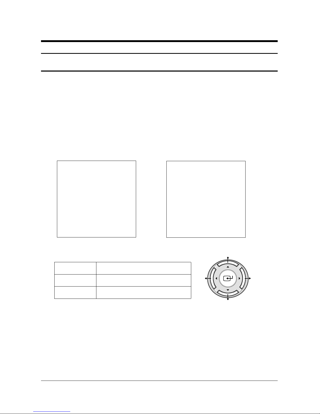
Initial display when the service mode is switched.
1-1-1 WHEN A RF SIGNAL IS RECEIVED
1-1-2 SERVICE MODE CONTROL KEYS
✍
PRECAUTIONS
1. When EEPROM IC (IC902) is replaced, first connect the power cord and wait for about 4~5 seconds.
2. After replacing EEPROM IC (IC902), enter the Service mode. Next, enter the standard data or the
previous EEPROM IC data before replacement. And then check and adjust any items related to
Geometric, Picture, Option.
DEFLECTION
VIDEO ADJUST 1
VIDEO ADJUST 2
VIDEO ADJUST 3
VIDEO ADJUST 4
OPTION (87h 05ch)
YC DELAY
RESET
T_CM2906_002 yy.mm.dd
MAIN MENU
UP / DOWN
RIGHT / LEFT
MENU DISPLAY
Select item by moving cursor
Decrease or increase the adjustment values
[Navigation Key]
MODEL((T_CM2P06_002)
DEFLECTION
VIDEO ADJUST 1
VIDEO ADJUST 2
VIDEO ADJUST 3
VIDEO ADJUST 4
OPTION (EF 8E 2E)
YC DELAY
RESET
T_CMDEAC_XXX yy.mm.dd
MODEL(T_CMDEAC_XXX)
Alignment and Adjustments
1-2 Samsung Electronics
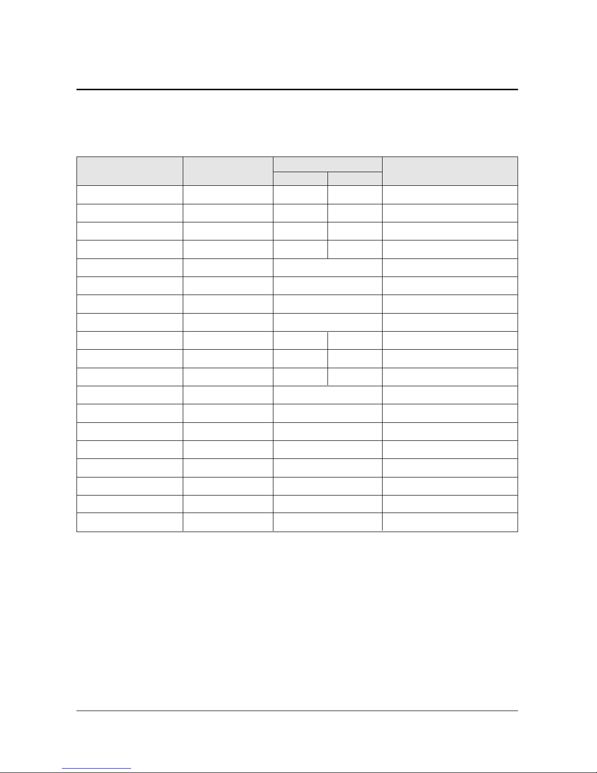
1-2 FACTORY MODE MENU
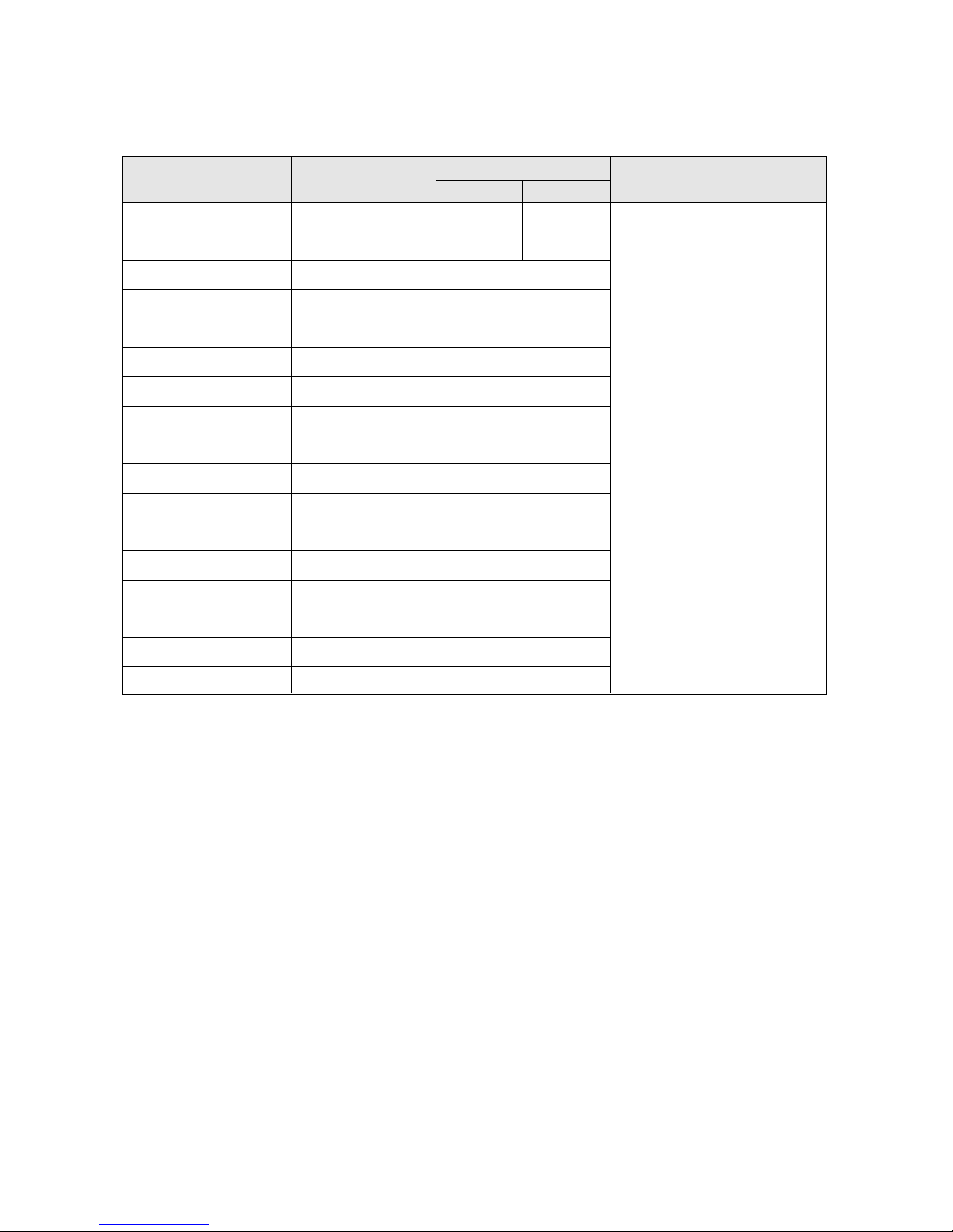
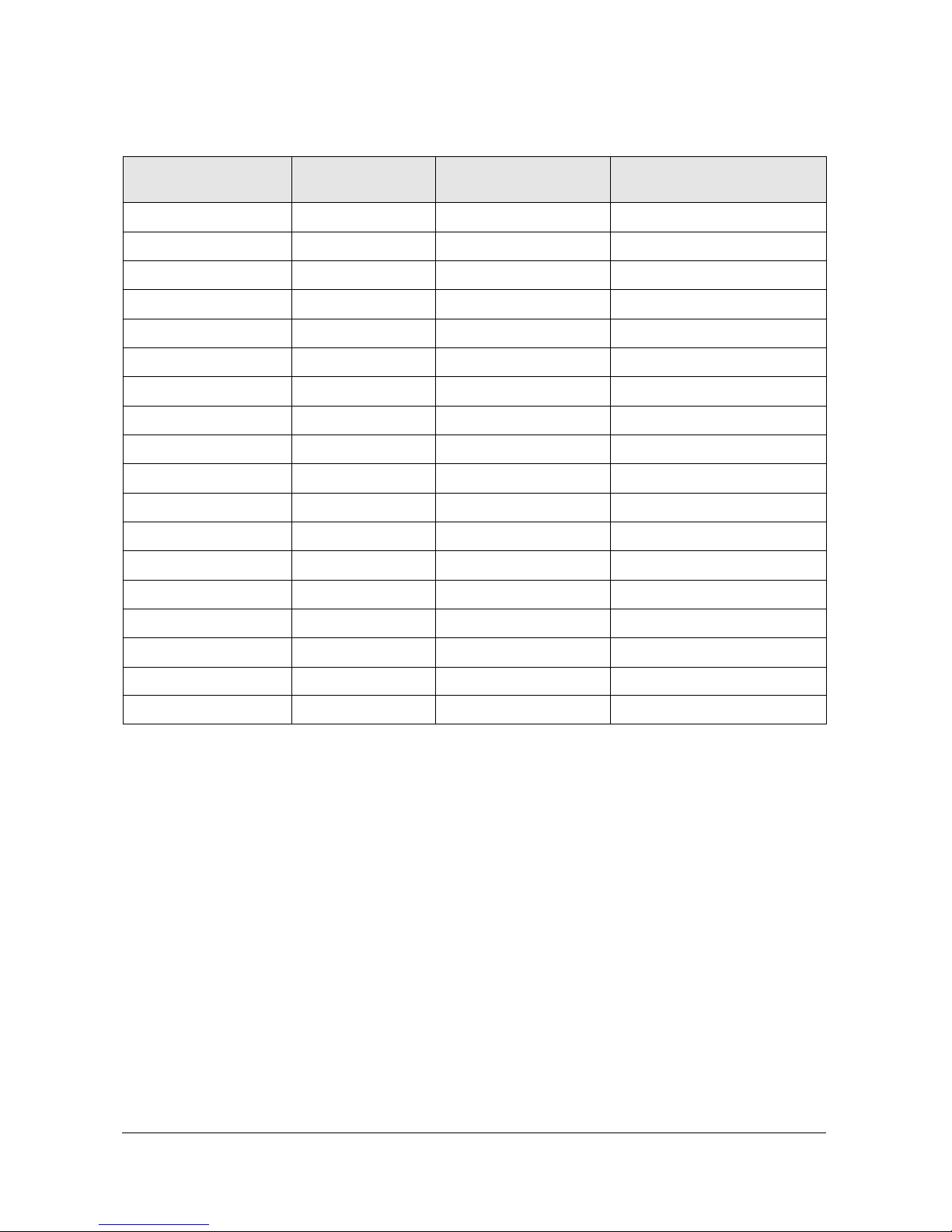
1-2-1(A) DEFLECTION
V Amp
V Shift
H EW
H Shift
V Linearity
Upper Linearity
Lower Linearity
V SC
H Parabolra
Upper Corner
Lower Corner
H Trapezium
Bow
Angle
V Position
Up UCG
Lo UCG
CXA Left Blk
CXA Right Blk
39 31
31 31
44 31
31 31
7
0
0
7
25 31
37 31
33 31
31
31
31
31
0
0
50
25
Item Range
Initial Data
4:3 Wide
0 ~ 63
0 ~ 63
0 ~ 63
0 ~ 63
0 ~ 15
0 ~ 15
0 ~ 15
0 ~ 15
0 ~ 63
0 ~ 63
0 ~ 63
0 ~ 63
0 ~ 63
0 ~ 63
0 ~ 63
0 ~ 3
0 ~ 3
0 ~ 63
0 ~ 63
Remark
Variable
FIX
Variable
FIX
FIX
FIX
FIX
FIX
FIX
FIX
FIX
FIX
FIX
FIX
FIX
FIX
FIX
FIX
FIX
1-2-1 MODEL(T_CM2906_002)
Alignment and Adjustments
Samsung Electronics 1-3
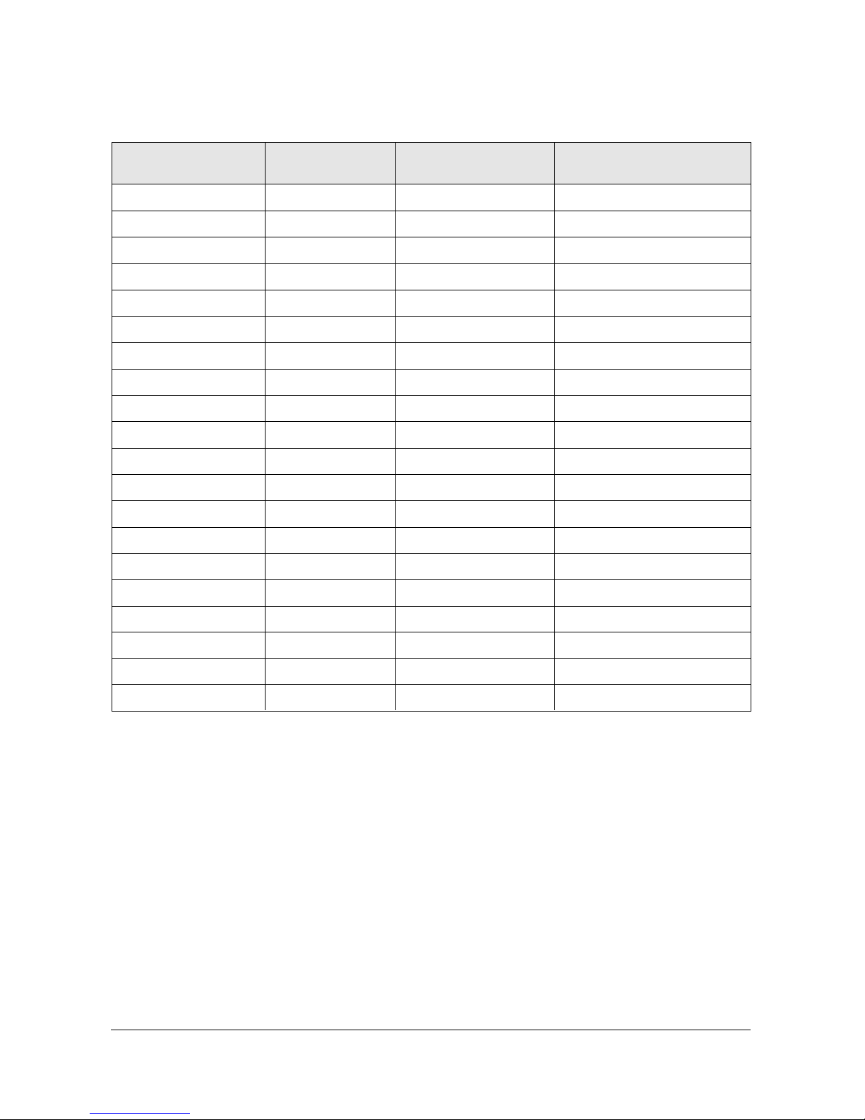
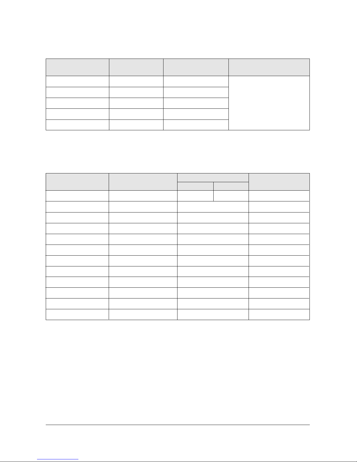
1-2-1(B) VIDEO ADJUST1
R Cutoff
G Cutoff
B Cutoff
Color On/Off
CB Offset
CR Offset
R Drive
G Drive
B Drive
Sub Bright
Sub Contrast
Sub Color
Sut Tint
CTI Level
COL Axis
LTI Level
VSU
Melody Volume
LIT Mode
System
25
25
25
1
31
31
25
25
25
15
8
3
31
1
1
1
2
7
1
1
Item Range
Initial Data
0 ~ 63
0 ~ 63
0 ~ 63
0 ~ 1
0 ~ 63
0 ~ 63
0 ~ 63
0 ~ 63
0 ~ 63
0 ~ 63
0 ~ 15
0 ~ 23
0 ~ 63
0 ~ 3
0 ~ 3
0 ~ 3
0 ~ 15
0 ~ 20
0 ~ 3
0 ~ 3
Remark
Variable
FIX
Variable
Variable
Variable
Variable
Variable
FIX
Variable
Variable
Variable
FIX
FIX
FIX
FIX
FIX
FIX
FIX
FIX
FIX

Alignment and Adjustments
1-4 Samsung Electronics
1-2-1(C) VIDEO ADJUST2
ABL Level
Gamma
DPIC Level
DC Trans
ABL TH
VM Level
VM Corint
VM f0
VM Limit
VM Delay
SHP CD
SHP f0
SHP f1 & P/O
AKB Time
BandPass 9407
HighPass 9407
S ABL
P ABL
3
1
2
3
15
1
0
1
1
1
0
1
11
13
24
40
0
15
Item Range
Initial Data
0 ~ 3
0 ~ 3
0 ~ 3
0 ~ 3
0 ~ 15
0 ~ 3
0 ~ 15
0 ~ 3
0 ~ 3
0 ~ 3
0 ~ 3
0 / 1
-
0 ~ 63
-
0 ~ 3
0 ~ 15
Remark
FIX
FIX
FIX
FIX
FIX
FIX
FIX
FIX
FIX
FIX
FIX
FIX
-
FIX
FIX
Alignment and Adjustments
Samsung Electronics 1-5
1-2-1(D) VIDEO ADJUST3
H Comp
V Comp
Pin Comp
AFC Comp
H-Sync Phase
NR Off Value
CG HAO
CG VAO
NR High Ref
NR Low Ref
NR High Value
NR Low Value
NR Hight Ref(S)
NR Low Ref(s)
NR High Value(S)
NR Low Value(S)
NR Read M/S
8 13
5 12
0
0
0
6
10
15
40
3
17
51
20
0
17
51
0 0
Item Range
Initial Data
4:3 Wide
0 ~ 15
0 ~ 15
0 ~ 7
0 ~ 7
0 / 1
0 ~ 9
0 ~ 20
0 ~ 20
0 ~127
0 ~127
0 ~255
0 ~255
0 ~127
0 ~127
0 ~255
0 ~255
0/27
Remark
FIX
Alignment and Adjustments
1-6 Samsung Electronics
1-2-1(E) VIDEO ADJUST4
SECAM Color Main
SECAM Color Pip
Picture Limit
OSD Contrast
TTX Contrast
28
28
3
10
3
Item Range
Initial Data
0 ~255
0 ~255
0 ~ 3
0 ~ 15
0 ~ 15
Remark
FIX
1-2-1(F) OPTION
SYSTEM
SOUND
ASPECT
WIDE 4:3
X-RAY
AUTO FM
PIP
LNA
Letter Box
TTX Lang.Grp
AGC
Natural Zoom
CW CS
Dolby Prlogic
-
ON
ON
ON
ON
ON
-
OFF
OFF
Item Setting Data
Appliance
CW CS
CS/CW
A2-NICAM/Dolby-Prologic
WIDE / 4:3
ON/OFF
ON/OFF
ON/OFF
ON/OFF
ON/OFF
ON/OFF
West/East/CIS/Turk&Grk
ON/OFF
ON/OFF
Area Option
Inch Option
Inch Option
-
-
-
-
-
Area Option
-
-
Remark
Alignment and Adjustments
Samsung Electronics 1-7
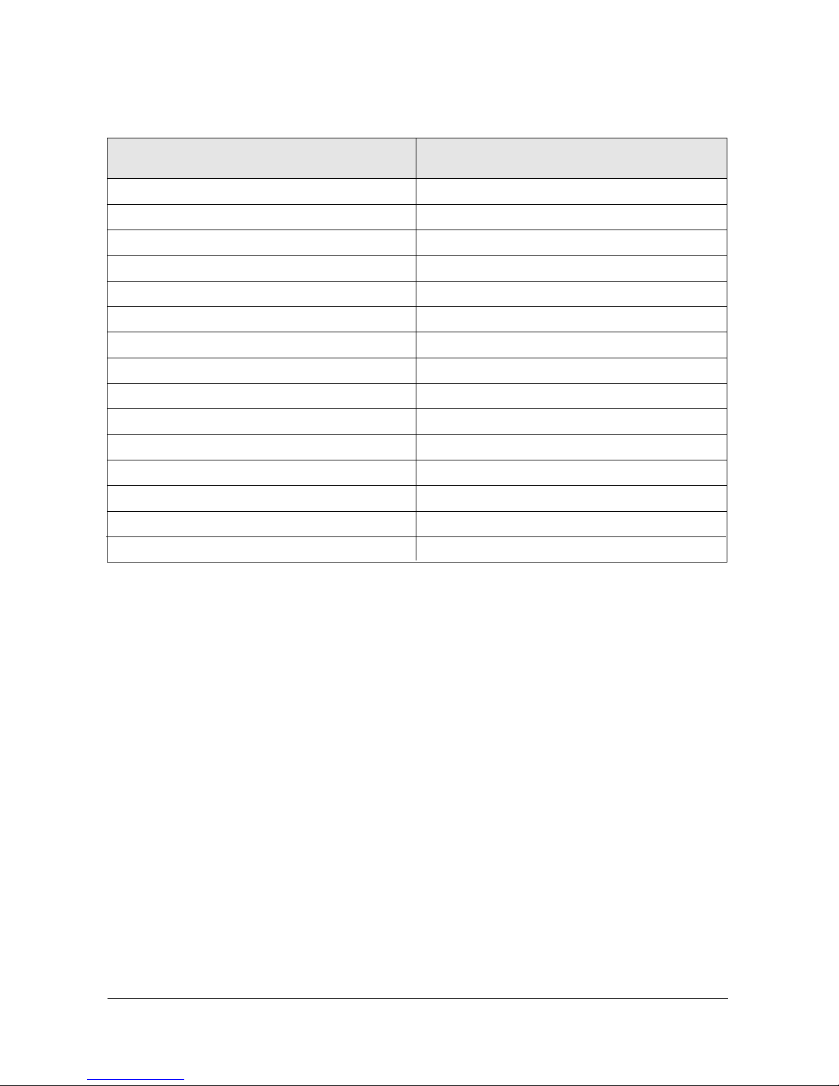
1-2-1(G) YC DELAY
P.YC(AV) Delay
S.YC(AV) Delay
N.YC(AV) Delay
P.BG.YC Dealy
P.DK.YC Delay
P.I.YC Delay
P.M.YC Delay
P.N.YC Delay
S.BG.YC Delay
S.DK.YC Delay
S.I.YC Delay
S.M.YC Delay
S.L.YC Delay
N.M.YC Delay
N4.43 YC Delay
Item Range
1
-5
1
1
-2
0
0
0
-7
-9
-9
-7
-10
3
-6
Alignment and Adjustments
1-8 Samsung Electronics
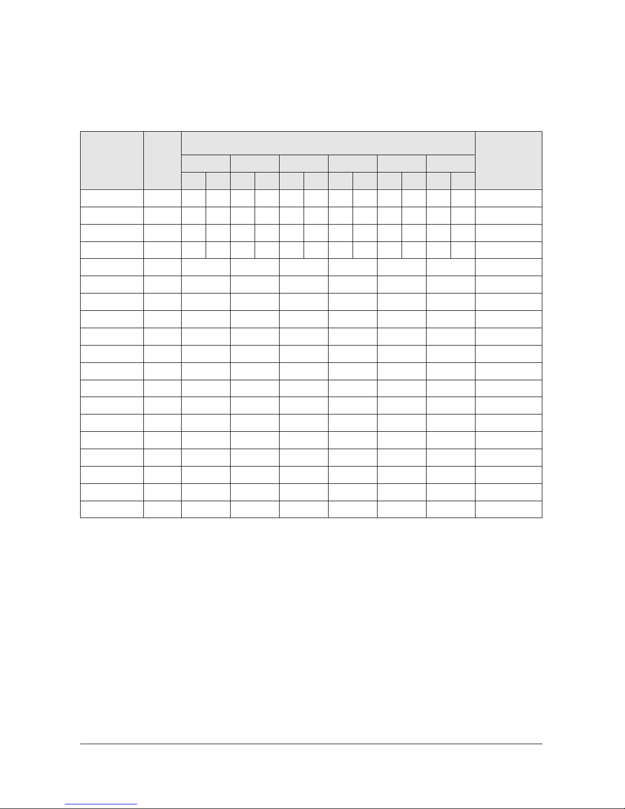
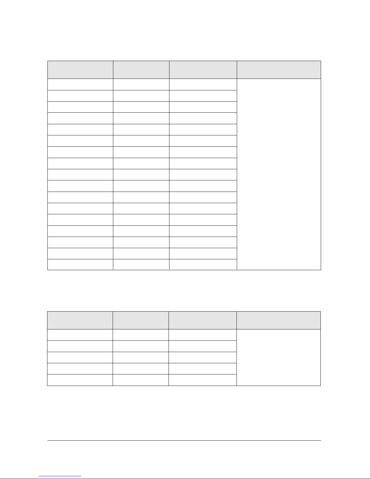
1-2-2(A) DEFLECTION
V Amp
V Shift
H EW
H Shift
V Linearity
Upper Linearity
Lower Linearity
V SC
H Parabolra
Upper Corner
Lower Corner
H Trapezium
Bow
Angle
V Position
Up UCG
Lo UCG
CXA Left Blk
CXA Right Blk
48
31
48
24
7
0
0
2
15
33
33
18
31
31
31
0
0
50
25
48
31
48
24
48
31
48
24
7
0
0
2
15
33
33
18
31
31
31
0
0
50
25
48
31
48
24
48
31
48
24
7
0
0
2
15
33
33
18
31
31
31
0
0
50
25
48
31
48
24
48
31
48
24
7
0
0
2
15
33
33
18
31
31
31
0
0
50
25
48
31
48
24
48
31
48
24
7
0
0
2
15
33
33
18
31
31
31
0
0
50
25
48
31
48
24
48
31
48
24
7
0
0
2
15
33
33
18
31
31
31
0
0
50
25
48
31
48
24
Item Range
Initial Data
0 ~ 63
0 ~ 63
0 ~ 63
0 ~ 63
0 ~ 15
0 ~ 15
0 ~ 15
0 ~ 15
0 ~ 63
0 ~ 63
0 ~ 63
0 ~ 63
0 ~ 63
0 ~ 63
0 ~ 63
0 ~ 3
0 ~ 3
0 ~ 63
0 ~ 63
Remark
Variable
FIX
Variable
FIX
FIX
FIX
FIX
FIX
FIX
FIX
FIX
FIX
FIX
FIX
FIX
FIX
FIX
FIX
FIX
1-2-2 CS MODEL(T_CMDEAC_XXX)
42W5
NTSC PAL
47W1
NTSC PAL
43T6/43T7
NTSC PAL
48T6
NTSC PAL
54T6
NTSC PAL
62T6
NTSC PAL

Alignment and Adjustments
Samsung Electronics 1-9
1-2-2(B) VIDEO ADJUST1
R Cutoff
G Cutoff
B Cutoff
Color On/Off
CB Offset
CR Offset
R Drive
G Drive
B Drive
Sub Bright
Sub Contrast
Sub Color
Sut Tint
CTI Level
COL Axis
LTI Level
VSU
Melody Volume
LIT Mode
System
20
20
20
1
31
31
31
31
31
20
8
15
31
1
2
1
2
4
1
1
Item Range
Initial Data
0 ~ 63
0 ~ 63
0 ~ 63
0 ~ 1
0 ~ 63
0 ~ 63
0 ~ 63
0 ~ 63
0 ~ 63
0 ~ 63
0 ~ 15
0 ~ 23
0 ~ 63
0 ~ 3
0 ~ 3
0 ~ 3
0 ~ 15
0 ~ 20
0 ~ 3
0 ~ 3
Remark
Variable
Variable
Variable
FIX
Variable
Variable
Variable
Variable
Variable
Variable
Variable
FIX
FIX
FIX
FIX
FIX
FIX
FIX
FIX
FIX
Alignment and Adjustments
1-10 Samsung Electronics
1-2-2(C) VIDEO ADJUST2
ABL Level
Gamma
DPIC Level
DC Trans
ABL TH
VM Level
VM Coring
VM f0
VM Limit
VM Delay
SHP CD
SHP f0
SHP f1 & P/O
AKB Time
BandPass 9407
HighPass 9407
S ABL
P ABL
3
1
3
2
15
2
0
1
1
1
0
1
11
13
24
40
0
15
Item Range
Initial Data
0 ~ 3
0 ~ 3
0 ~ 3
0 ~ 3
0 ~ 15
0 ~ 3
0 ~ 15
0 ~ 3
0 ~ 3
0 ~ 3
0 ~ 3
0 / 1
-
0 ~ 63
-
0 ~ 3
0 ~ 15
Remark
FIX
FIX
FIX
FIX
FIX
FIX
FIX
FIX
FIX
FIX
FIX
FIX
FIX
FIX
FIX
FIX
FIX
FIX
Alignment and Adjustments
Samsung Electronics 1-11
1-2-2(D) VIDEO ADJUST3
H Comp
V Comp
Pin Comp
AFC Comp
H-Sync Phase
NR Off Value
CG HAO
CG VAO
NR High Ref
NR Low Ref
NR High Value
NR Low Value
NR Hight Ref(S)
NR Low Ref(s)
NR High Value(S)
NR Low Value(S)
NR Read M/S
2
4
3
0
0
6
10
15
40
3
17
51
20
0
17
51
0 0
Item Range
Initial Data
0 ~ 15
0 ~ 15
0 ~ 7
0 ~ 7
0 / 1
-
0 ~ 20
0 ~ 20
0 ~127
0 ~127
-
0 ~127
0 ~127
-
-
-
Remark
FIX
1-2-2(E) VIDEO ADJUST4
SECAM Color Main
SECAM Color Pip
Picture Limit
OSD Contrast
TTX Contrast
28
28
3
10
3
Item Range
Initial Data
0 ~255
0 ~255
0 ~ 3
0 ~ 15
0 ~ 15
Remark
FIX
Alignment and Adjustments
1-12 Samsung Electronics
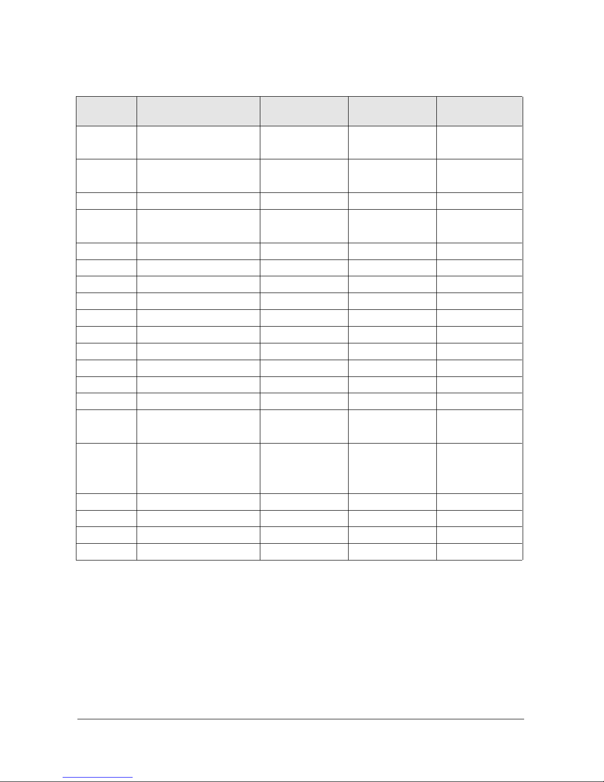
1-2-2(F) OPTION
LANGUAGE
SOUNG
CRT
CHANNEL
X-LAY
TTX
AUTO FM
PIP
MULTI PIP
LNA
HIGH DEV
SCART
LETTER BOX
DW PIP
LIST PRIOR
TTX LANG
AGC
AV MEMORY
AUSTRALIA
CG BRIGHT
ONLY ENG
ENG+THAI(Thailand)
Dolby Prologic
4:3(Option)
100-channel
ON
ON
ON
2-TUNER
ON
ON
OFF
RCA+1SCART+DVD
ON
ON
OFF
0N(AUSTRALIA)
WEST EUROPE
OFF/0N(Thailand)
OFF
OFF
OFF
Item Setting Data
Appliance
(Southeast Asia)
ENG+CHINA
Dolby Prologic
4:3(Option)
200-channle
ON
OFF
ON
2-TUNER
ON
ON
OFF
RCA+DVD
ON
ON
OFF
WEST EUROPE
OFF
OFF
OFF
OFF
Appliance
(CHINA)
ENG+MIDDLE
Dolby Prologic
4:3(Option)
250-channle
ON
ON
ON
2-TUNER
ON
ON
OFF
RCA+1SCART+DVD
ON
ON
OFF
ARABIC
OFF
OFF
OFF
OFF
Appliance
(Middle East)
ENG+THAI / ENG+CHINA
ENG+MIDDLE / ONLY ENG
A2-NICAM/Virtual Dolby
/Dolby Prologic
WIDE / 4:3
100-channel / 200-channel
/250-chanel
OFF / ON
OFF / ON
OFF / ON
OFF / 2-TUNER
OFF / ON
OFF / ON
OFF / ON
RCA+1SCART+DVD / RCA+DVD
OFF / ON
OFF / ON
OFF / ON
WEST EUROPE / EAST EUROPE
RUSSIAN / GREEK-TURKEY
ARABIC / FARSI / AREB-HEBREW
OFF / ON
OFF / ON
OFF / ON
OFF/ON
Alignment and Adjustments
Samsung Electronics 1-13
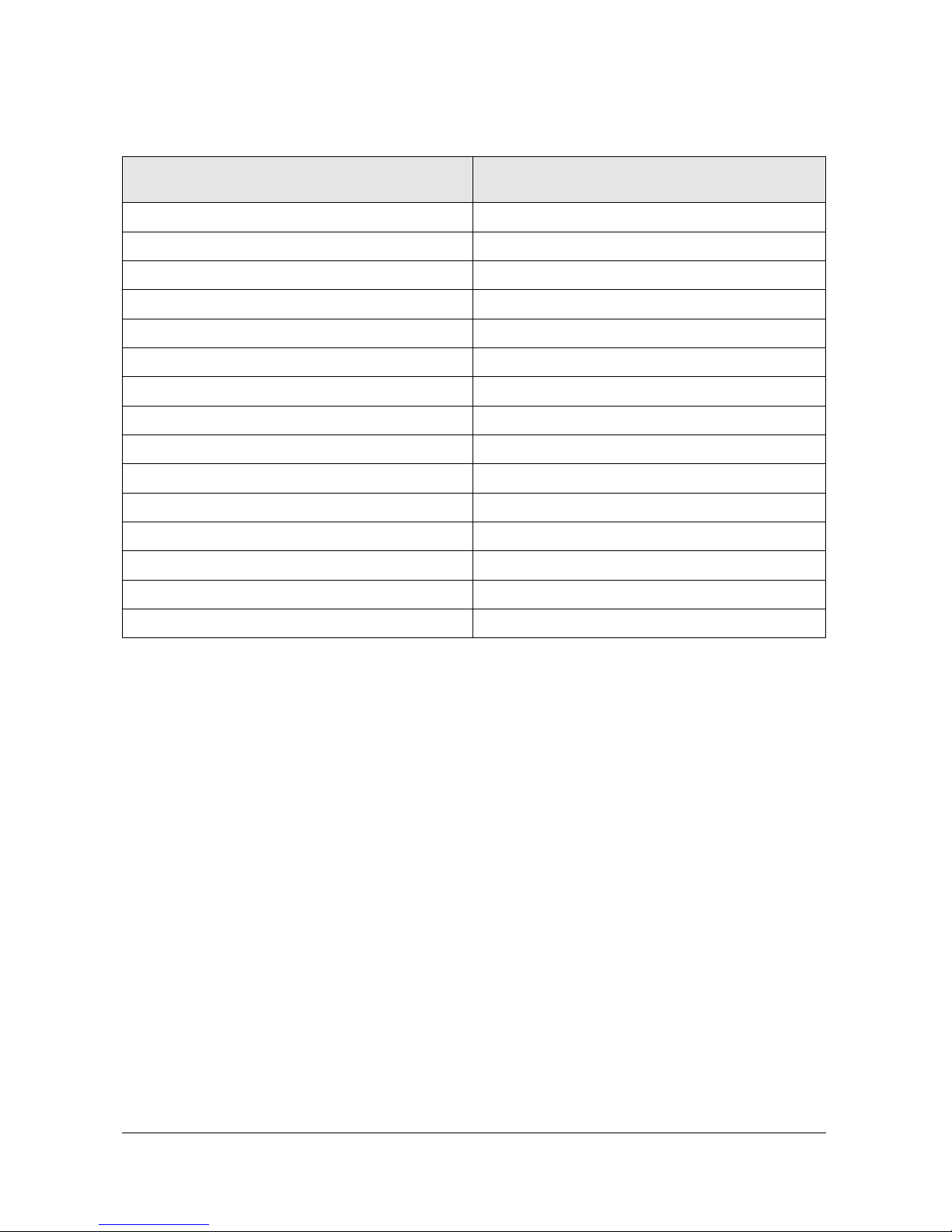
1-2-2(G) YC DELAY
P.YC(AV) Delay
S.YC(AV) Delay
N.YC(AV) Delay
P.BG.YC Dealy
P.DK.YC Delay
P.I.YC Delay
P.M.YC Delay
P.N.YC Delay
S.BG.YC Delay
S.DK.YC Delay
S.I.YC Delay
S.M.YC Delay
S.L.YC Delay
N.M.YC Delay
N.443.YC Delay
Item Range
1
-5
1
1
-2
-2
0
0
-7
-10
-9
-7
-10
3
-1
Alignment and Adjustments
1-14 Samsung Electronics
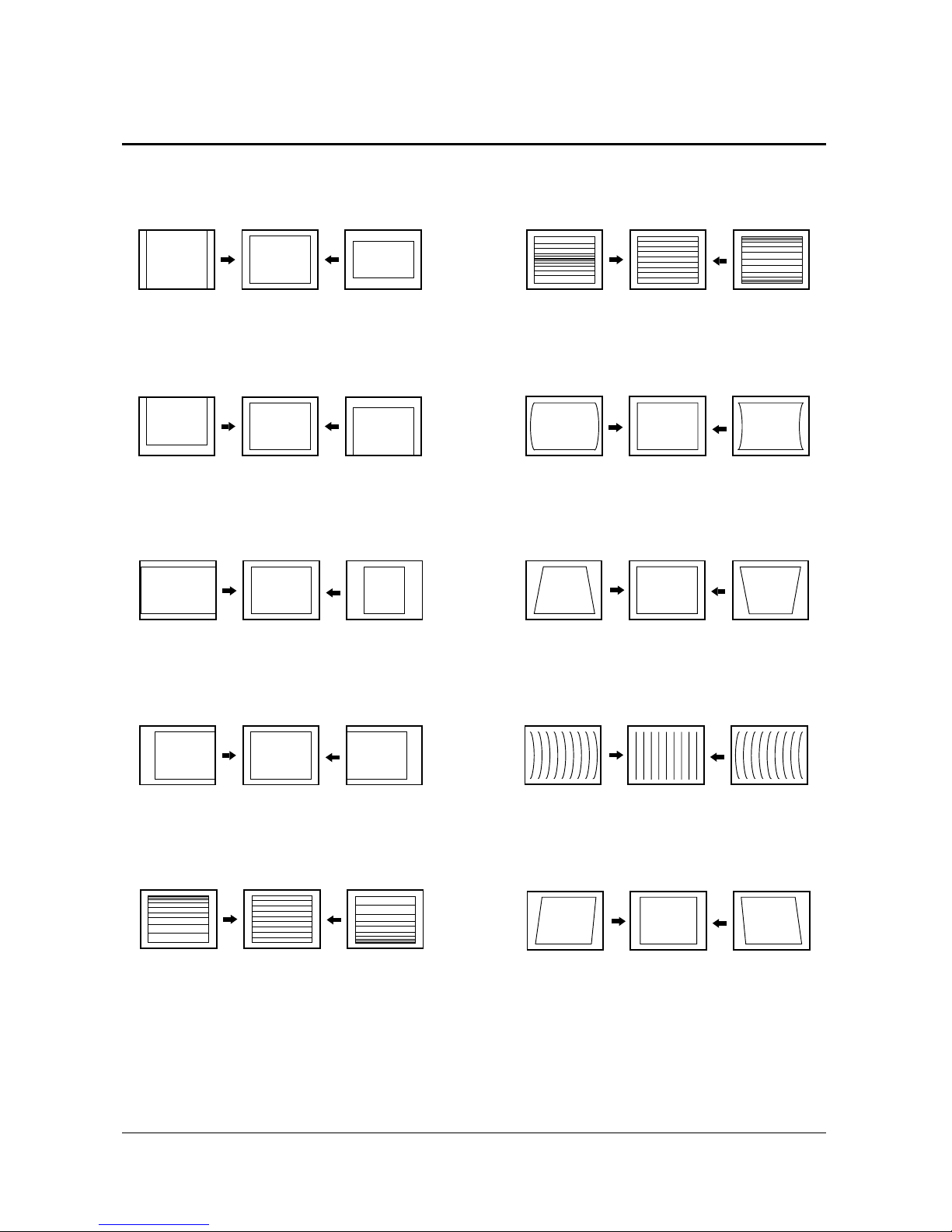
1-3 Screen Change (When Adjusting I2C Bus Geometric Items)
8
H Trapezium
9 BOW
10 ANGLE
7
H Parabolra
5 V LINEARITY
1 V AMP
3 H EW
4 H SHIFT
6 V - S - CORRECTION
2 V SHIFT

Alignment and Adjustments
Samsung Electronics 1-15
1-4 Other Adjustments
1-4-1 Screen Adjustment
1. Warm up the TV for at least 30 minutes.
2. Select the “DYNAMIC” Video mode.
3. Trun to the Video Mode(No Signal) using a
remote-control.
4. Connect an oscilloscope to RK, GK, BK.
5. Adjust the VR (VR501, VR531, VR561) screen
so that RK, GK, BK pulse is 20Vp-p each.
(Turn the R,G,B VR screen fully
counterclockwise in the area of each flyback
line.)
1-4-2 White Balance Adjustment
1. Select the “DYNAMIC” video mode.
2. Input 100% white pattern.
3. In the stand-by mode, press the remote-control
keys in the following sequence:
Displsy → Menu → Mute → Power ON
4. Warm up the TV for at least 30 minutes.
5. Input a 10-step signal.
6. R-cut off, B-cut off, and G-cut off by pressing
the Volume +/- keys.
7. Adjust the low light with viewing the dark
side of the screen.
8. Select R-drive, G-drive and B-drive by
pressing the Volume +/- keys.
9. Adjust the high light with viewing the light
side of the screen.
10. If necessary, redo adjustments 6~9.
11. Press the Menu key to exit.
1-4-3 Sub-Brightness Adjustment
1. Input a sub-brightness adjustment signal.
(TOSHIBA PATTERN)
2. In the stand-by mode, press the remote-control
keys in the following sequence :
Displsy → Menu → Mute → Power ON
3. Select Sub-Bright by pressing the Volume +/keys.
4. Adjust so that the 63 step on the right side of
the screen is not seen (Use the Volume +/keys).
5. Press the Menu key to exit.
1-4-4 High Voltage (29KV) Check
PRECAUTION
1. Input a lion head pattern.
2. Select “DYNAMIC” video mode.
3. Warm up the TV for at least 10 minutes.
4. Use a 1000:1 probe.
ADJUSTMENT
1. Connect the (+) terminal of the 10000:1 probe
to the high voltage distributor and the(-)
terminal to GND(located on the deflection
board).
2. Adjust RR471S (located on the deflection
board) so that the digital meter indicates
DC290V ± 0.1V.
4-4-5 F.S. (Fail Safe) Circuit Check
Note : The finished product has a well-mounted
VR(RR402S).
If necessary, do the F.S adjustments in the
following sequece.
1. Use a digital multimeter.
2. Connect the digital multimeter to the JIG pin
(DZ482S) terminals.
3. Adjust VR(RR402S) so that the voltage becoms
2.25V.
4. After the adjustments are complete be sure to
mount VR(RR402S) correctly.
Alignment and Adjustments
1-16 Samsung Electronics
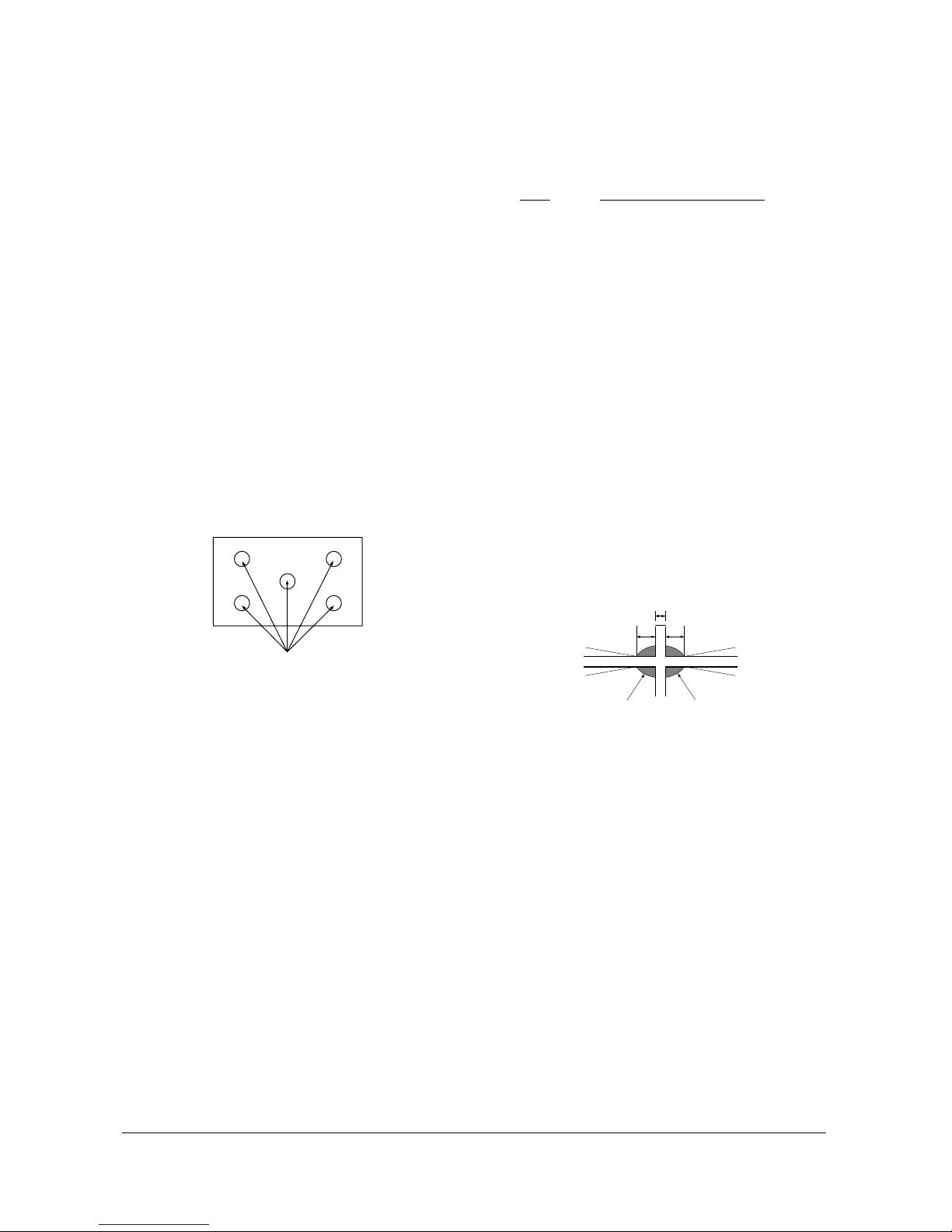
1-4-6 Static Focus Adjustment
PRECAUTION
1. Select the “DYNAMIC” video mode.
2. Input a crosshatch pattern.
3. Cover the lenses that are not being adjusted.
4. Connect a convergence jig and read data.
5. Adjust the lens for best focus.
(See Fig, 4-1)
STATIC FOCUS (CONTINUED)
Vary the focus pack VR (Red, Blue) on the
front cabinet. Adjust the TV for best possible
focus around the center of the crosshatch
pattern, without losing overall screen balance.
Figure Crosshatch Pattern
Examine these points together.
1-4-7 Lens Focus Adjustment
PRECAUTIONS
1. Do this adjustment after the static focus
adjustment and the tilt adjustment.
2. Select the “DYNAMIC” video mode.
(Contrast:100, Brightness:50)
3. Input a crosshatch pattern.
ADJUSTMENT
1. Loosen the lens screws.
2. Cover the two lenses that are not being
adjusted.
3. Adjust the lens, observing the color aberration
vertically and horizontally within 3 blocks of
the center of the crosshatch pattern.
4. When the lens is turned clockwise, the color
aberration will change as follows:
Lens Color
Aberration Change
R Orange - Crimson
G Blue - Red
B Purple - Green
5. Green lens adjustment:
Set the lens at the point where Blue just
changes to Red. If the color aberration is
irregular throughout the picture screen, adjust
the lens to show Red color aberration
(approximately 1~3 mm area) within a 3-block
grid around the horizontal center-line. If the
color aberration is irregular, adjust the lens as
shown in the diagram below. (Accurate
alignment of Green is important for overall
color quality.)
6. Red lens adjustment
Set the Red lens at the point where Orange
becomes Crimson.
7. Blue lens adjustment
Set the Blue lens at the point where Purple
becomes Green.
P
L1
L2
RED ABERRATION
BLUE ABERRATION
L1, L2 < P
_
Fig. 4-1 Crosshatch Pattern.
Examine these points together
Fig. 4-2 Color Aberration
Alignment and Adjustments
Samsung Electronics 1-17
1. Select the “DYNAMIC” video mode.
2. Warm up the set at least for 10 minutes.
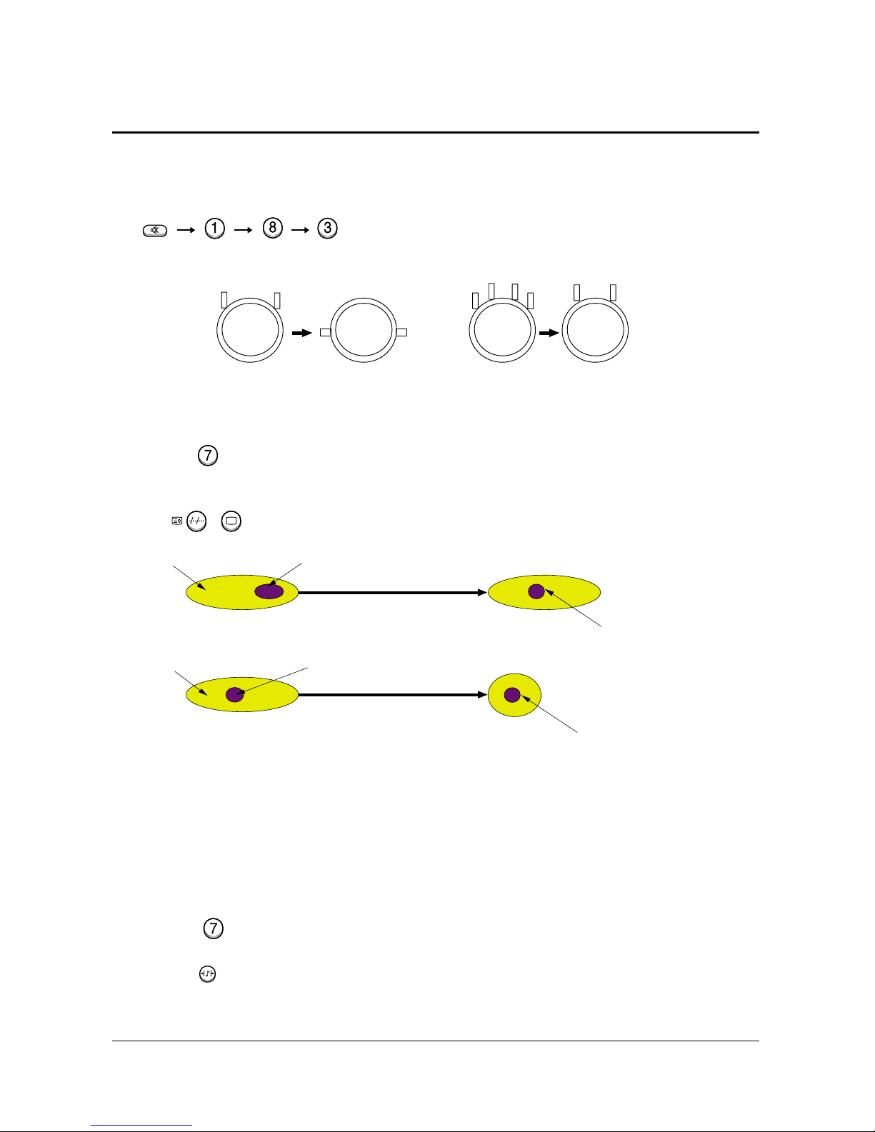
3. Enter the Convergence mode by pressing the remote control buttons in the following sequence :
4. Set the Beam Alignment Adjustment CY to Zero magnetic field area.
5. Check the squarewave at the point where the focus is misaligned.
6. Press the button on the remote control during 3~5 sec and vibrating dot-pattern appears.
7. Adjust the Focus-pack VR for defocusing.
8. Mute the other patterns (R/B) other than G-PATTERN.
(Use / buttons on the remote control.)
9. Adjust the 2, 4 polarities of VM-COIL as shown in figure below.
10. Adjust the G-Focus until any light around the core disappears.
11. Adjust G-Focus so that the surrounding flash can disappear from the spot.
12. After G-Focus adjustments are complete, adjust R-Focus as above procedures.
13. The B-CRT adjustments can be omitted because the variance of beam focus is small.
(Only Vm-coil is mounted.)
14. Adjust the Focus-pack VR for fine focusing.
15. Press the button on the remote control, and the mode changes to the Convergence Adjustment
mode.
16. Press the button on the remote control to return to normal viewing.
(Creation of CPM Zero Magnet)
(Creation of the 2-pole/4-pole zero magnets)
G-FOCUS
CORE
(Varying G-Focus Pack)
Varying the 2-pole of VM
(Positioning the Core in the Center)
Varying the 4-pole of VM
CORE
G-FOCUS
(When VM 2-Pole Adjustment is completed)
(Adjust until the light around
the core becomes a circle)
1-5 Beam alignment Adjustments
Mute
TV
S.STD
Alignment and Adjustments
1-18 Samsung Electronics
1-6 High Voltage Part
1-6-1 PWM REG Circuit
For the existing high voltage REG circuit (input
voltage variation type), a dynamic REG response
is not provided. So it is difficult for both beam
linearity and uniformity in screen size to be
maintained on the screen with rapidly changing
beams.
A PWM (Pulse Width Modulation) type of high
voltage, however, provides the maintenance of
beam linearity and uniformity in screen size via a
quick response to beam change by performing
sync lock every 1H line, and detecting beam
fluctuation at 1H line, and then controlling the IC
current of high voltage output circuit.
1. High Voltage Fluctuation Detect (DC Detect)
FBT pin 11 detects DC high voltage fluctuation.
The detected DC high voltage value is input to
PWM IC471 pin1 through R473, VR471, R471,
and then it is input to a differential AMP circuit
that differentiates the gap after comparing with
the reference voltage input to pin2.
2. High Voltage Fluctuation Detect (AC Detect)
To check AC high voltage fluctuation, the
output from FBT is detected by using a
capacitor inside the high voltage distributor. The
detection of AC high voltage fluctuation,
a detection of dynamic beam current change is
required in order to keep beam linearity and
uniformity in size.
Regarding the capacitor, a capacity of less than
3000P should be applied to a PWM type. (The
existing type needs a capacity of about 6000P.)
AC detect circuit eliminates unnecessary high
frequency by using C476, D472. Also, AC gain is
limited to + / - 0.7V (D472). This AC gain is
combined with the detection value of DC high
voltage fluctuation by using C478.
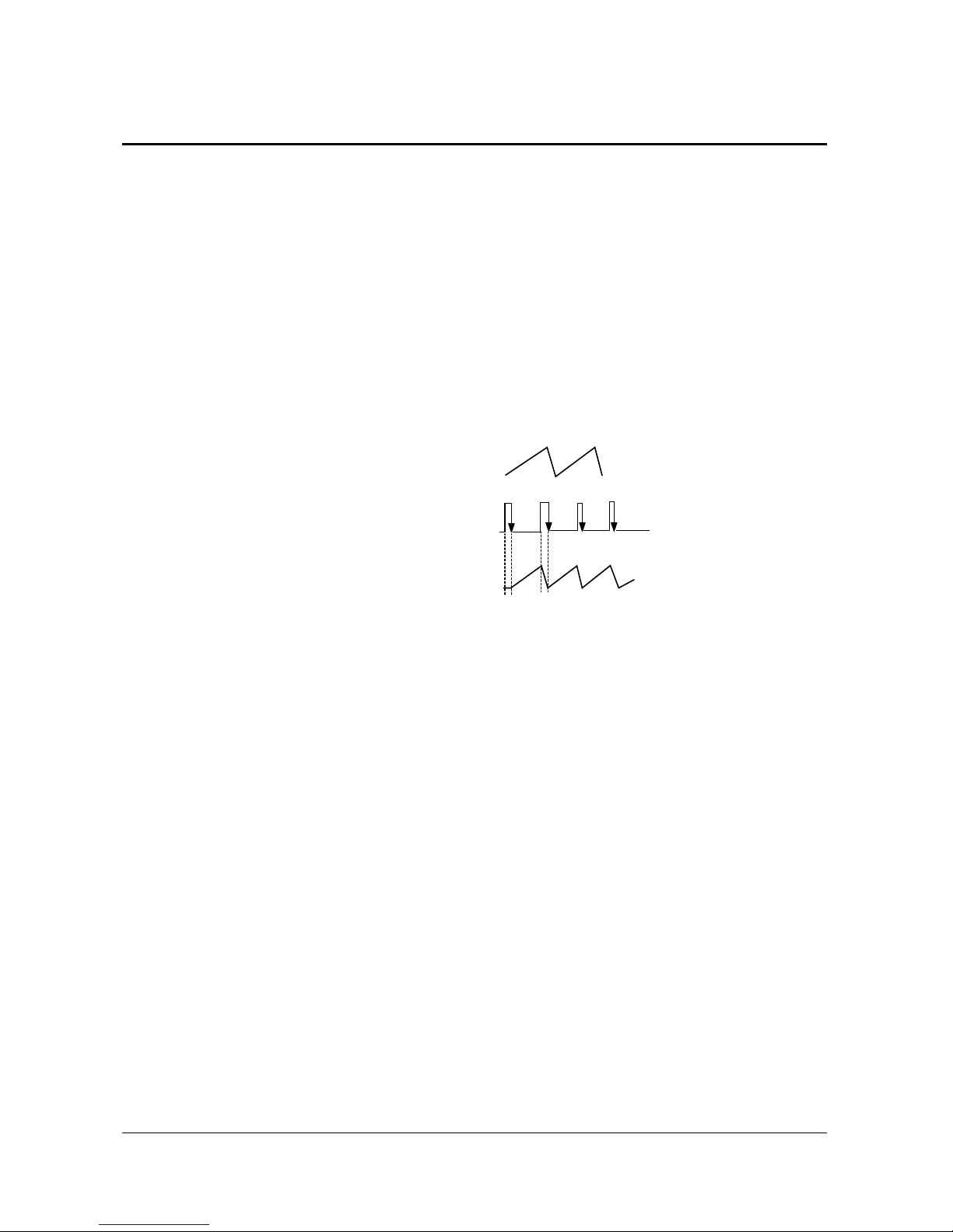
3. PWM IC OSC Sync Lock
A PWM type IC needs sync lock for PWM pulse
and horizontal scan line.
The standard time constant of OSC circuit is
determined by C487, R475 (PWM IC pins 5 and 6).
And the standard OSC frequency is about 27
kHz . The horizontal frequency of scan line is
31.5kHz(NT), 31.25kHz(PAL), so sync lock for this
horizontal frequency should be performed using
sync lock circuit. The sync lock circuit consists
of Q481(Tr KSC815-Y), D479, D478, and C492.
The input AFC signal is connected to PWM IC
pin 5 through D479 so that it can be negative
Trig.
4. Dead Time (HV Protect)
Dead Time (PWM IN pin4) consists of C481,
delays high voltage for a certain time to soft
start in power on, a x-ray protection circuit.
The voltage of Dead Time is detected by FBT
pin7 and through DC Feedback. The normal
voltage of Dead Time is +27V. When high
voltage increases, however, detected voltage is
in proportion to high voltage. Then, the detected
voltage is applied to ICR01S(TL431).
If the voltage is over 2.5V (normal:about 2.25V),
TL431 turns ON, the base port of QR401S
becomes low, and then an emitter current flows.
At this time, a high voltage protection point is
set. When QR401S turns ON, high voltage is
applied to PWM IC pin4 and then muted.
OSC : 27KHz
AFC Waveform : 31.5KHz(NT)
Locked OSC Waveform : 31.5KHz
Alignment and Adjustments
Samsung Electronics 1-19
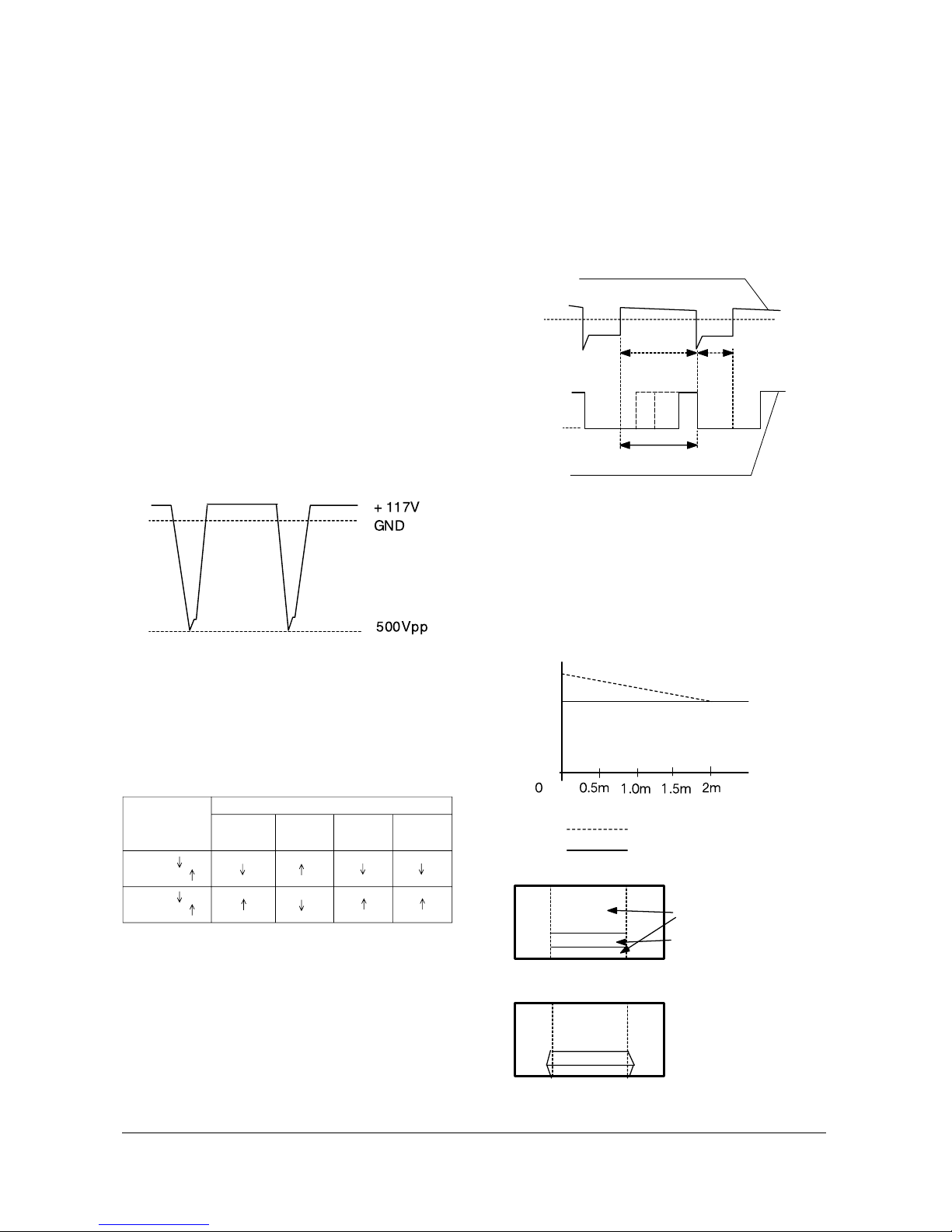
5. Output Circuit
The voltages, which are detected form an error
detection circuit of PWM IC (Differential AMP)
and Dead Time, each is applied to PWM
conparator . Due to these detection coltages, Q1,
Q2 (Output TR) parallel operate. Q482 (External
TR), however, functions as a buffer; natches
inpedance between the output port of PWM IC
and the final output TR(IRFS640). The PWM
pulse (applied to the final output FET (IRFS640
GATE) varies the IC current of high voltage
TR(Q473) by adjusting the load impedance of
starage Trans (T431). Due to this variation of
current, the gain for Q473 emitter pulse changes
T444(FBT)makes this emitter pulse became high
voltage. Such change keeps both dynamic and
static changes fixed. The output waveform of
high valtage TR emitter is as shown in the figure
below.
6. Paraneters according to beam
To maintain the set high voltage value (31kV),
parmaters such as +Ve (DC), Vcp High Voltage
change (See the table below).
7. Response Waveform
To reduce unstable high voltage fluctuation, the
existing high voltage type REG circuit controls
dynamic fluctuation by using C-block capacitor.
But, it can't detect actual dynamic fluctuation.
Also, its velocity of response to static fluctuation
is late because +B power supply changes per
about 1V. A PWM modulation type REG detects
static, dynamic high voltage fluctuation for only
Ton Time (when the current of the output TR
collector flows) each 1H, and modulates the
width of PWM pulse. So, this PWM type has
better improvement in the characteristic of high
voltage REG as compared to the existing type.
8. Application Effects
1) Improvement of horizontal size fluctuation
2) Linearity improved
3) Embodiment of X-ray protection circuit
The figures below show characteristics when a
PWM high voltage REG circuit is applied.
Beam
(High voltage )
Factor of high
voltage change
Beam
(High voltage )
Width of FET
Gate Pulse
+ Ve (DC)
Vcp
High
Voltage
Parameters
High Voltage Drive Base Current
PWM Input Waveform of FET GATE
GND
GND
PWM Variation tange
Ton Toff
Beam
High Voltage
High Voltage OFF
High Voltage REG ON
BLACK
WHITE
When a Toshiba Pattern
is recrived, the screen is
displayed as shown in
figute side
Existing type
PWM type
Alignment and Adjustments
1-20 Samsung Electronics
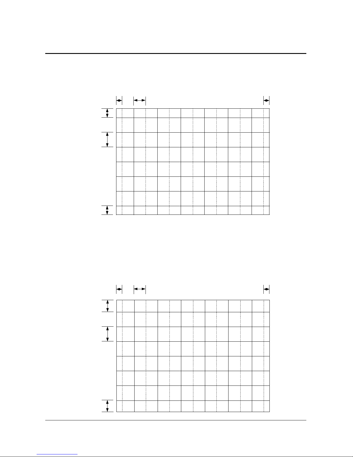
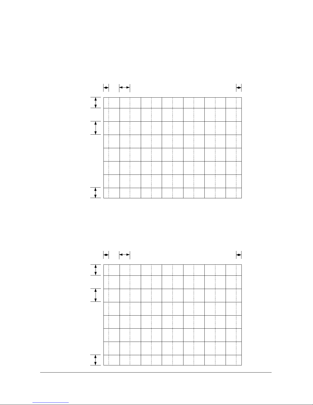
1-6 SCREEN-JIG
26.84mm 73.19mm
34.00mm
76.00mm
26.84mm
34.00mm
30.09mm 82.07mm
38.15 mm
85.28mm
30.09mm
38.15mm
42W5 Screen Size : X 932, Y 524 (X:764 = 22 x 2 + 60 x 12, Y:262 = 17 x 2 + 38 x 6)-PAL MODE
47W3 Screen Size : X 1045, Y 588 (X:764 = 22 x 2 + 60 x 12, Y:262 = 17 x 2 + 38 x 6)-PAL MODE
1-6-1 42W5
1-6-2 47W3
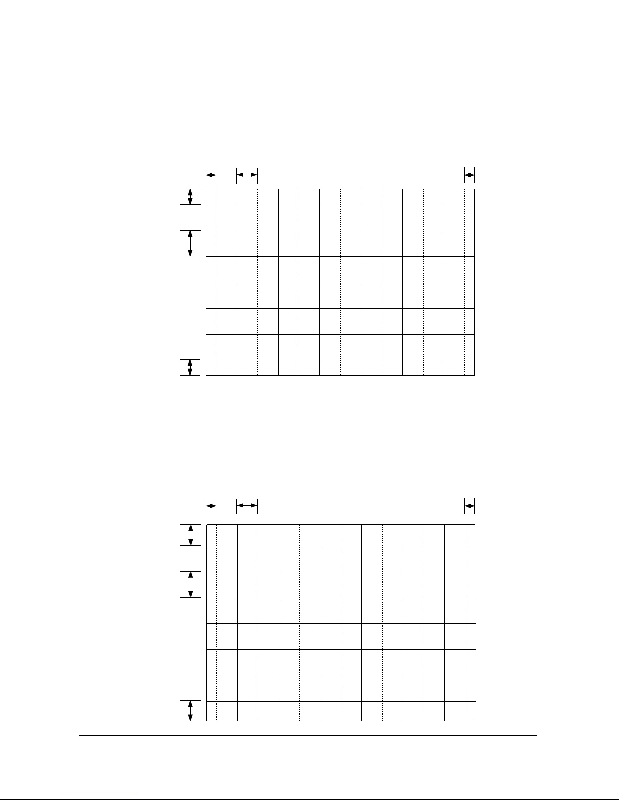
Alignment and Adjustments
Samsung Electronics 1-21
35.27mm 96.20mm
44.51mm
99.50mm
35.27mm
44.51mm
41.52mm
131
.2 5 mm
54.37 mm
211.54mm
41.52mm
54.37mm
55W3 Screen Size : X 1225, Y 686 (X:764 = 22 x 2 + 60 x 12, Y:262 = 17 x 2 + 38 x 6)-PAL MODE
65W3 Screen Size : X 1442, Y 838 (X:764 = 22 x 2 + 60 x 12, Y:262 = 17 x 2 + 38 x 6)-PAL MODE
1-6-3 55W3
1-6-4 65W3
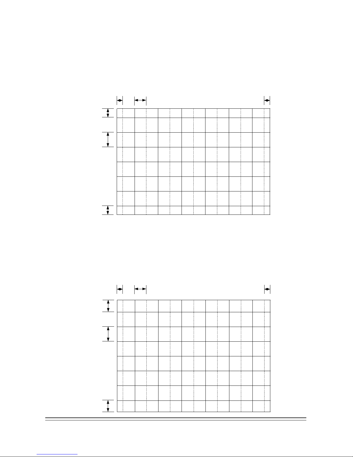
Alignment and Adjustments
1-22 Samsung Electronics
25.48mm 69.50mm
43.21mm
96.60mm
25.48mm
43.21mm
28.03mm 28.03mm
7
6.45mm
47.91 mm
47.91 mm
071.10mm
43T6 Screen Size : X 885, Y 666 (X:764 = 22 x 2 + 60 x 12, Y:262 = 17 x 2 + 38 x 6)-PAL MODE
48T6 Screen Size : X 973.4 Y 738.4 (X:764 = 22 x 2 + 60 x 12, Y:262 = 17 x 2 + 38 x 6)-PAL MODE
1-6-5 43T6/43T7
1-6-6 48T6
Alignment and Adjustments
Samsung Electronics 1-23
31 8.6 5mm 31.65mm6.3 1mm
53.40 mm
53.40 mm
191.37mm
54T6 Screen Size : X 1099 Y 823 (X:764 = 22 x 2 + 60 x 12, Y:262 = 17 x 2 + 38 x 6)-PAL MODE
36 9.2 7 mm 8 .8 1 mm
61.51 mm
371.50mm
36.27mm
61.51mm
62T6 Screen Size : X 1259.4, Y 948 (X:764 = 22 x 2 + 60 x 12, Y:262 = 17 x 2 + 38 x 6)-PAL MODE
1-6-7 54T6
1-6-8 62T6
1-24 Samsung Electronics
Alignment and Adjustments
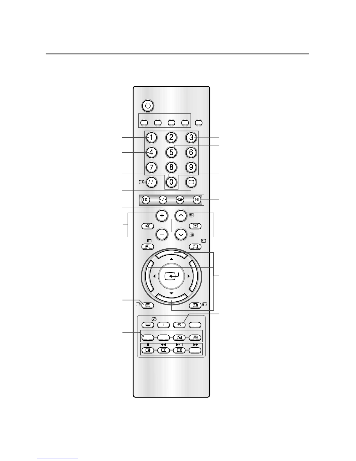
1-7 Remote Control for Servicing(Convergence Mode)
SET
DVDCable
VCRTV
TV
Surround
S.STD
P.STD
S.Mode
Text/Mix Info. Sleep
Perfect Focus
PIP Scan Swap Locate
StillMute
VOL P
Menu Video
Display P.Size
ON
Power
Last Data Save button/CanccelConvergence Data
R-Mute
B-Mute
Exit Button
Test Normal
Convergence Data
Left/Right Move Button
G-Mute
LINE Adjust
ENTIRE Adjust
B-Selete
Save Button
Convergence Data
UP/DOWN Move Button
Convergence Data
UP/DOWN Move Button
Convergence H-PHASE
Move Button(Right)
Cg Factory Data
Select Key(Each Inch)
R-Selete
G-Selete
Convergence H-PHASE
Move Button(Left)

Alignment and Adjustments
Samsung Electronics 1-25
Display
TV
S.STD
S.Mode
1-7-1 KEY Function
1. R-SELECT
Press to select RED color.
2. G-SELECT
Press to select GREEN color.
3. B-SELECT
Press to select BLUE color.
4. R-MUTE
Press to mute RED color.
5. G-MUTE
Press to mute GREEN color.
6. B-MUTE
Press to mute BLUE color.
7. CANCEL KEY
Press to revert to the previous data during the Convergence Adjustment.
8. TEST/NORMAL
Press to check TV mode in the Convergence Mode.
9. LINE SHIFT
Press to move a line up/down or left/right.
10. FACTORY DATA SELECT BUTTON
Press to call the factory default values.
11. SAVE BUTTON
After the Convergence Adjustments are completed, press to save data.
12. EXIT BUTTON
After the Convergence adjustments are completed, press to exit to TV mode.
Alignment and Adjustments
1-26 Samsung Electronics
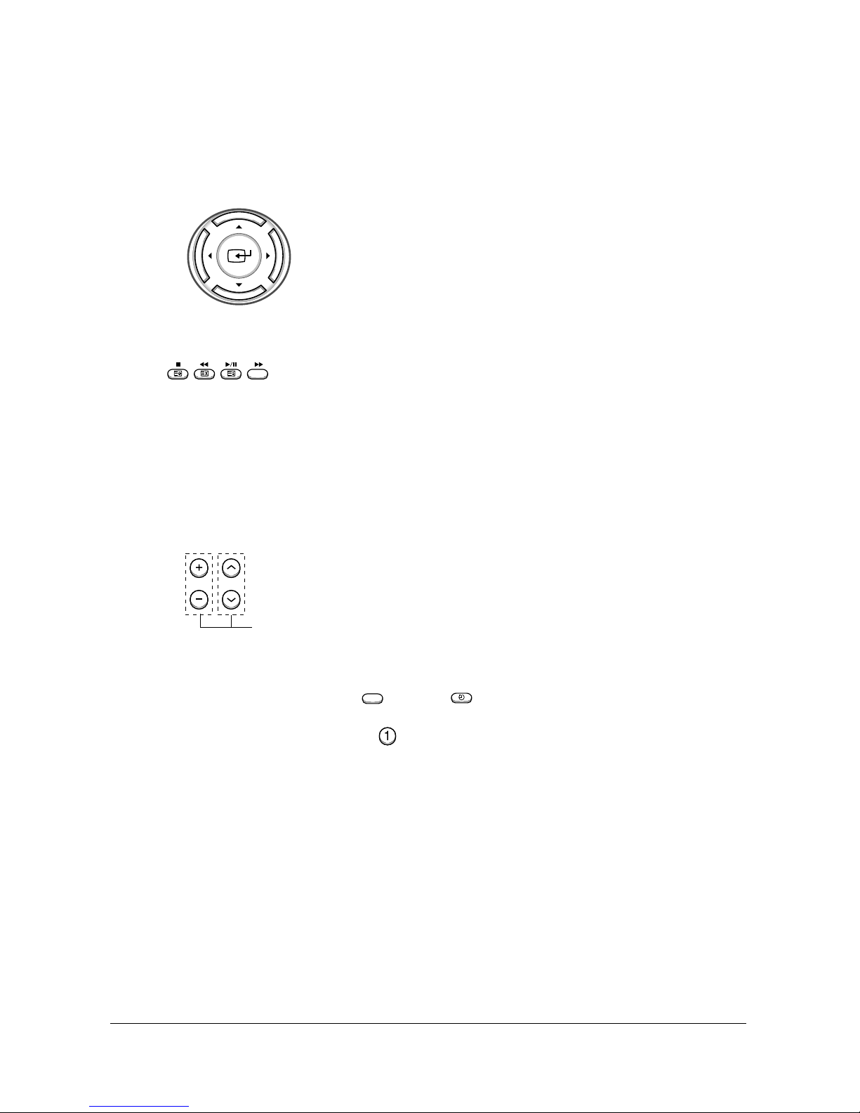
UP
LEFT RIGHT
DOWN
VOL P
Cg -Data Move Button
Sleep
PIP
ON
UP DOWN LEFT RIGHT
(Right)
(Left)
(Up)
(Down)
13. CURSOR MOVE BUTTON
Press to move the cursor up/down or right/left.
!
@
# (Mute) Press to move the cursor left or up.
(Video) Press to move the cursor right or down.
(Menu) Press switch the cursor direction horizontally or vertically.
14. CONVERGENCE PICTURE MOVE BUTTON
15. CONVERGENCE MOVE BUTTON
Press to move the convergence right ( ) or left ( ) .
16. CONVERGENCE DATA ZERO BUTTON
Press to zero the convergence correction data.
Alignment and Adjustments
Samsung Electronics 1-27
Locate
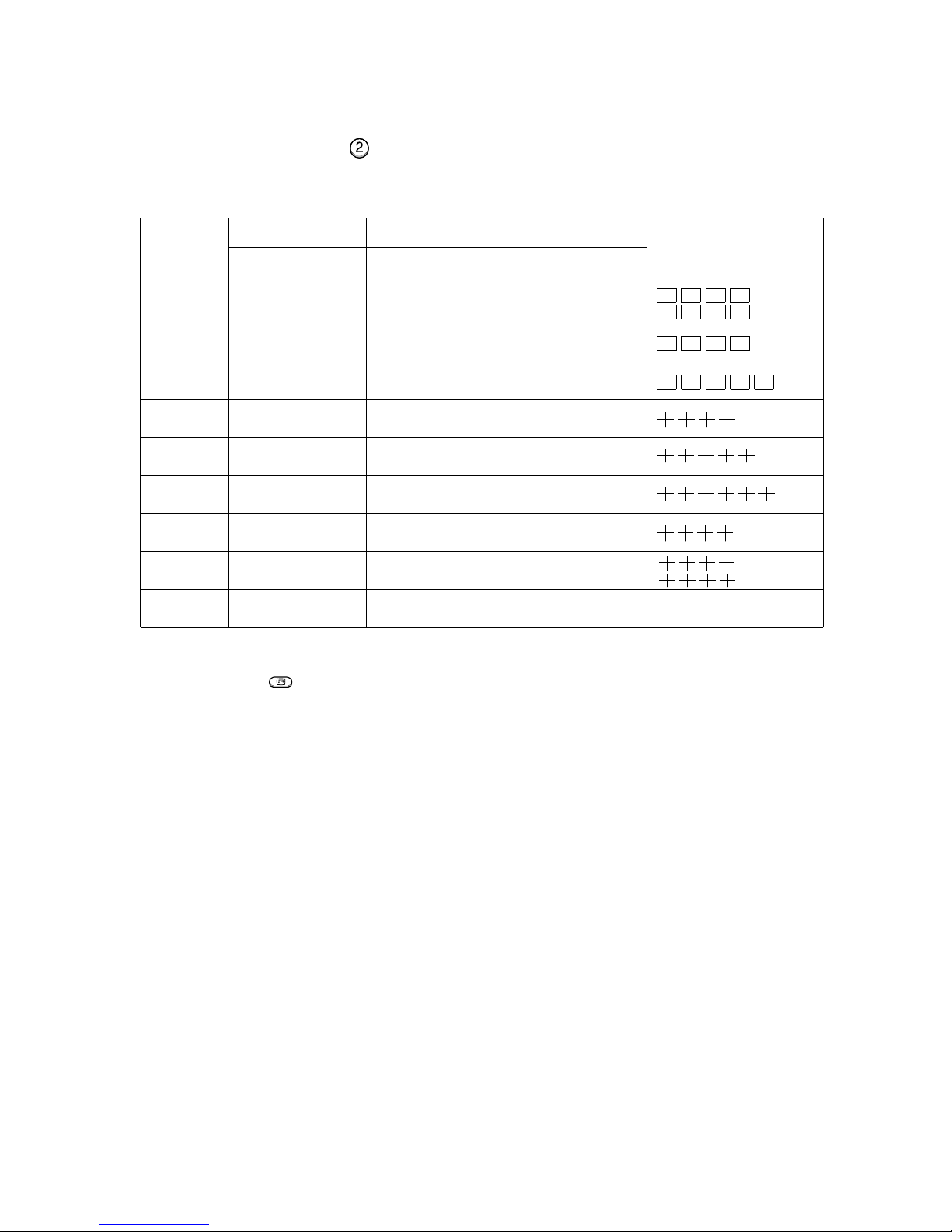
17. INITIAL DATA SET BUTTON
18. Data shift Button Press to transmit data(PAL Mode/NTSC Mode).
Inch (Type)
42” (42W5)
47” (47W3)
55” (55W3)
43” (43T6
43” (43T7)
48” (48T6)
54” (54T6)
62” (62T6)
65”(65W3)
Model Name
Representative
Model
SP42W5
SP47W3
SP55W3
SP43T6
SP43T7
SP48T6
SP54T6
SP62T6
SP65W3
Basic Data
Number after entring
the Cg-Mode
5-425 (Press in regular order)
5-473(Press in regular order)
5-553(Press in regular order)
5-436(Press in regular order)
5-437(Press in regular order)
5-485(Press in regular order)
5-545(Press in regular order)
5-625(Press in regular order)
Screen Display
Changes when applying Almighty-Cg, Module (How to extract the basic Cg Data)
Alignment and Adjustments
1-28 Samsung Electronics
Mute
S.STD
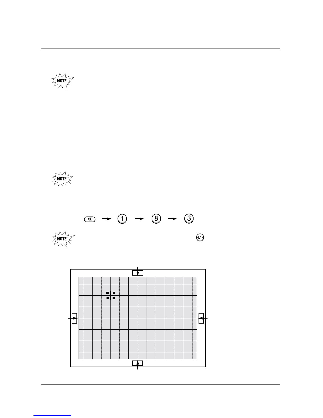
1-8 Convergence Adjustment
1-8-1 Convergence Adjustment
Special Notes
✏ A sensor is attached on the center of each side of the Convergence Mode pattern
(see figure below). The sensors are required for normal Perfect Focus function.
✏ Use a screen jig to do the convergence adjustments correctly (Especially, perform
correct convergence adjustments on the center of each side where a sensor is located.)
✏ Do the convergence adjustments correctly. Otherwise, any Perfect Focus error can
happen.
1. Warm up the TV for a least 30 minutes.
2. Input an PAL Signal.(Use an antenna or AV source.)
Make sure that deflection yoke are properly adjusted so that the center of
Green, Red, Blue pattern is aligned on the center of screen jig.
3. Enter the Convergence Mode by Pressing the remote control keys in the following sequence:
If OSD displayed as shown in figure below, press the key to exit.
Then, redo step 3 to enter the Convergence Mode.
After entering the Convergence Mode, Stand by for about five seconds
before doing the adjustments.
 Loading...