

Samsung SP47W3HFX/COM, SP47W3HFX/EUE, SP47W3HFX/BOB, SP55W3HFX/XEC, SP47W3HFX/XEH Service Manual

PROJECTION TV RECEIVER
Chassis : J52A(P)_REV.4
Model: SP47W3HFX/BOB
SP47W3HFX/COM
SP47W3HFX/EUE
SP47W3HFX/XEH
SP55W3HFX/XEC
PROJECTION TV RECEIVER CONTENTS
Precautions
Reference Information
Specifications
Alignment and Adjustments
Troubleshooting
Exploded View and Parts List
Electric Parts List
Block Diagrams
Wiring Diagram
Schematic Diagrams
1.
2.
3.
4.
5.
6.
7.
8.
9.
10.

ELECTRONICS
© Samsung Electronics Co., Ltd. Nov. 2002
Printed in Korea
3J52A-SESA-47W3
1. Precautions
1-1 Safety Precautions
1. Be sure that all of the built-in protective
devices are replaced. Restore any missing
protective shields.
2. When reinstalling the chassis and its
assemblies, be sure to restore all protective
devices, including: nonmetallic control knobs
and compartment covers.
3. Make sure that there are no cabinet openings
through which people—particularly
children—might insert fingers and contact
dangerous voltages. Such openings include
the spacing between the picture tube and the
cabinet mask, excessively wide cabinet
ventilation slots, and improperly fitted back
covers.
If the measured resistance is less than 1.0
megohm or greater than 5.2 megohms, an
abnormality exists that must be corrected
before the unit is returned to the customer.
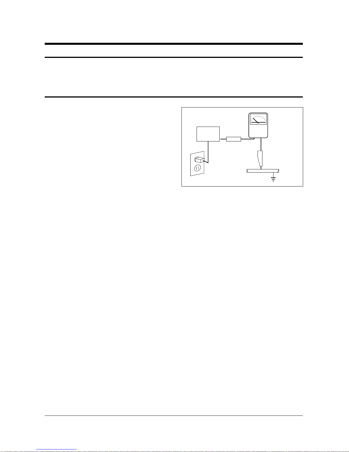
4. Leakage Current Hot Check (Figure 1-1):
Warning: Do not use an isolation
transformer during this test. Use a leakagecurrent tester or a metering system that
complies with American National Standards
Institute (ANIS C101.1, Leakage Current for
Appliances), and Underwriters Laboratories
(UL Publication UL1410, 59.7).
5. With the unit completely reassembled, plug
the AC line cord directly into the power
outlet. With the unit’s AC switch first in the
ON position and then OFF, measure the
current between a known earth ground (metal
water pipe, conduit, etc.) and all exposed
metal parts, including: antennas, handle
brackets, metal cabinets, screwheads and
control shafts. The current measured should
not exceed 0.5 milliamp. Reverse the powerplug prongs in the AC outlet and repeat the
test.
Fig. 1-1 AC Leakage Test
6. Antenna Cold Check:
With the unit’s AC plug disconnected from the
AC source, connect an electrical jumper across
the two AC prongs. Connect one lead of the
ohmmeter to an AC prong. Connect the other
lead to the coaxial connector.
7. X-ray Limits:
The picture tube is especially designed to prohibit X-ray emissions. To ensure continued
X-ray protection, replace the picture tube only
with one that is the same type as the original.
Carefully reinstall the picture tube shields and
mounting hardware; these also provide X-ray
protection.
8. High Voltage Limits:
High voltage must be measured each time servicing is done on the B+, horizontal deflection
or high voltage circuits. Correct operation of
the X-ray protection circuits must be
reconfirmed whenever they are serviced.
(X-ray protection circuits also may be called
“horizontal disable” or “hold-down”.)
Heed the high voltage limits. These include
the X–ray Protection Specifications Label, and
the Product Safety and X-ray Warning Note on
the service data schematic.
Precautions
Samsung Electronics 1-1
LEAKAGE
CURRENT
TESTER
DEVICE
UNDER
TEST
TEST ALL
EXPOSED METAL
SURFACES
2-WIRE CORD
ALSO TEST WITH
PLUG REVERSED
(USING AC ADAPTER
PLUG AS REQUIRED)
EARTH
GROUND
(READING SHOULD
NOT BE ABOVE
0.5mA)
Follow these safety, servicing and ESD precautions to prevent damage and protect against potential
hazards such as electrical shock and X-rays.

1-1 Safety Precautions (Continued)
9. High voltage is maintained within specified
limits by close-tolerance, safety-related
components and adjustments. If the high
voltage exceeds the specified limits, check
each of the special components.
10. Design Alteration Warning:
Never alter or add to the mechanical or
electrical design of this unit. Example: Do not
add auxiliary audio or video connectors. Such
alterations might create a safety hazard. Also,
any design changes or additions will void the
manufacturer’s warranty.
11. Hot Chassis Warning:
Some TV receiver chassis are electrically
connected directly to one conductor of the AC
power cord. If an isolation transformer is not
used, these units may be safely serviced only
if the AC power plug is inserted so that the
chassis is connected to the ground side of the
AC source.
To confirm that the AC power plug is inserted
correctly, do the following: Using an AC
voltmeter, measure the voltage between the
chassis and a known earth ground. If the
reading is greater than 1.0V, remove the AC
power plug, reverse its polarity and reinsert.
Re-measure the voltage between the chassis
and ground.
12. Some TV chassis are designed to operate with
85 volts AC between chassis and ground,
regardless of the AC plug polarity. These units
can be safely serviced only if an isolation
transformer inserted between the receiver and
the power source.
13. Some TV chassis have a secondary ground
system in addition to the main chassis ground.
This secondary ground system is not
isolated from the AC power line. The two
ground systems are electrically separated by
insulating material that must not be defeated
or altered.
14. Components, parts and wiring that appear to
have overheated or that are otherwise
damaged should be replaced with parts that
meet the original specifications. Always
determine the cause of damage or overheating, and correct any potential hazards.
15. Observe the original lead dress, especially
near the following areas: Antenna wiring,
sharp edges, and especially the AC and high
voltage power supplies. Always inspect for
pinched, out-of-place, or frayed wiring. Do
not change the spacing between components
and the printed circuit board. Check the AC
power cord for damage. Make sure that leads
and components do not touch thermally hot
parts.
16. Picture Tube Implosion Warning:
The picture tube in this receiver employs
“integral implosion” protection. To ensure
continued implosion protection, make sure
that the replacement picture tube is the same
as the original.
17. Do not remove, install or handle the picture
tube without first putting on shatterproof
goggles equipped with side shields. Never
handle the picture tube by its neck. Some
“in-line” picture tubes are equipped with a
permanently attached deflection yoke; do not
try to remove such “permanently attached”
yokes from the picture tube.
18. Product Safety Notice:
Some electrical and mechanical parts have
special safety-related characteristics which
might not be obvious from visual inspection.
These safety features and the protection they
give might be lost if the replacement component differs from the original—even if the
replacement is rated for higher voltage,
wattage, etc.
Components that are critical for safety are
indicated in the circuit diagram by shading,
( ) or ( ).
Use replacement components that have the
same ratings, especially for flame resistance
and dielectric strength specifications.
A replacement part that does not have the
same safety characteristics as the original
might create shock, fire or other hazards.
Precautions
1-2 Samsung Electronics

1-2 Servicing Precautions
1. Servicing precautions are printed on the
cabinet. Follow them.
2. Always unplug the unit’s AC power cord from
the AC power source before attempting to: (a)
Remove or reinstall any component or
assembly, (b) Disconnect an electrical plug or
connector, (c) Connect a test component in
parallel with an electrolytic capacitor.
3. Some components are raised above the printed
circuit board for safety. An insulation tube or
tape is sometimes used. The internal wiring is
sometimes clamped to prevent contact with
thermally hot components. Reinstall all such
elements to their original position.
4. After servicing, always check that the screws,
components and wiring have been correctly
reinstalled. Make sure that the portion around
the serviced part has not been damaged.
5. Check the insulation between the blades of the
AC plug and accessible conductive parts
(examples: metal panels, input terminals and
earphone jacks).
6. Insulation Checking Procedure: Disconnect the
power cord from the AC source and turn the
power switch ON. Connect an insulation
resistance meter (500V) to the blades of the AC
plug.
The insulation resistance between each blade
of the AC plug and accessible conductive parts
(see above) should be greater than 1 megohm.
7. Never defeat any of the B+ voltage interlocks.
Do not apply AC power to the unit (or any of
its assemblies) unless all solid-state heat sinks
are correctly installed.
8. Always connect a test instrument’s ground
lead to the instrument chassis ground before
connecting the positive lead; always remove
the instrument’s ground lead last.
9. When some parts inside the optical engine
(except lamp) are damaged, replace the whole
optical engine.
Precautions
Samsung Electronics 1-3
Warning 1 : First read the “Safety Precautions” section of this manual. If some unforeseen circumstance creates a
conflict between the servicing and safety precautions, always follow the safety precautions.
Warning 2 : An electrolytic capacitor installed with the wrong polarity might explode.
“CAUTION : Double-pole/neutral fusing”

1-3 Precautions for Electrostatically Sensitive Devices (ESDs)
1. Some semiconductor (“solid state”) devices
are easily damaged by static electricity. Such
components are called Electrostatically
Sensitive Devices (ESDs); examples include
integrated circuits and some field-effect
transistors. The following techniques will
reduce the occurrence of component damage
caused by static electricity.
2. Immediately before handling any semicon
ductor components or assemblies, drain the
electrostatic charge from your body by
touching a known earth ground. Alternatively,
wear a discharging wrist-strap device. (Be
sure to remove it prior to applying power—
this is an electric shock precaution.)
3. After removing an ESD-equipped assembly,
place it on a conductive surface such as
aluminum foil to prevent accumulation of
electrostatic charge.
4. Do not use freon-propelled chemicals. These
can generate electrical charges that damage
ESDs.
5. Use only a grounded-tip soldering iron when
soldering or unsoldering ESDs.
6. Use only an anti-static solder removal device.
Many solder removal devices are not rated as
“anti-static”; these can accumulate sufficient
electrical charge to damage ESDs.
7. Do not remove a replacement ESD from its
protective package until you are ready to
install it. Most replacement ESDs are
packaged with leads that are electrically
shorted together by conductive foam,
aluminum foil or other conductive materials.
8. Immediately before removing the protective
material from the leads of a replacement ESD,
touch the protective material to the chassis or
circuit assembly into which the device will be
installed.
9. Minimize body motions when handling
unpackaged replacement ESDs. Motions such
as brushing clothes together, or lifting a foot
from a carpeted floor can generate enough
static electricity to damage an ESD.
Precautions
1-4 Samsung Electronics

Reference Information
Samsung Electronics 2-1
2. Reference Information
2-1 Tables of Abbreviations and Acronyms
A
Ah
Å
dB
dBm
°C
°F
°K
F
G
GHz
g
H
Hz
h
ips
kWh
kg
kHz
kΩ
km
km/h
kV
kVA
kW
I
MHz
Ampere
Ampere-hour
Angstrom
Decibel
Decibel Referenced to One
Milliwatt
Degree Celsius
Degree Fahrenheit
degree Kelvin
Farad
Gauss
Gigahertz
Gram
Henry
Hertz
Hour
Inches Per Second
Kilowatt-hour
Kilogram
Kilohertz
Kilohm
Kilometer
Kilometer Per Hour
Kilovolt
Kilovolt-ampere
Kilowatt
Liter
Megahertz
MV
MW
MΩ
m
µA
µF
µH
µm
µs
µW
mA
mg
mH
mI
mm
ms
mV
nF
Ω
pF
Ib
rpm
rps
s
V
VA
W
Wh
Megavolt
Megawatt
Megohm
Meter
Microampere
Microfarad
Microhenry
Micrometer
Microsecond
Microwatt
Milliampere
Milligram
Millihenry
Milliliter
Millimeter
Millisecond
Millivolt
Nanofarad
Ohm
Picofarad
Pound
Revolutions Per Minute
Revolutions Per Second
Second (Time)
Volt
Volt-ampere
Watt
Watt-hour
Table 2-1 Abbreviations

Reference Information
2-2 Samsung Electronics
Table 2-2 Table of Acronyms
ABL
AC
ACC
AF
AFC
AFT
AGC
AM
ANSI
APC
APC
A/V
AVC
BAL
BPF
B-Y
CATV
CB
CCD
CCTV
Ch
CRT
CW
DC
DVM
EIA
ESD
ESD
FBP
FBT
FF
FM
FS
GND
G-Y
H
HF
HI-FI
IC
IC
IF
Automatic Brightness Limiter
Alternating Current
Automatic Chroma Control
Audio Frequency
Automatic Frequency Control
Automatic Fine Tuning
Automatic Gain Control
Amplitude Modulation
American National Standards Institute
Automatic Phase Control
Automatic Picture Control
Audio-Video
Automatic Volume Control
Balance
Bandpass Filter
Blue-Y
Community Antenna Television (Cable TV)
Citizens Band
Charge Coupled Device
Closed Circuit Television
Channel
Cathode Ray Tube
Continuous Wave
Direct Current
Digital Volt Meter
Electronics Industries Association
Electrostatic Discharge
Electrostatically Sensitive Device
Feedback Pulse
Flyback Transformer
Flip-Flop
Frequency Modulation
Fail Safe
Ground
Green-Y
High
High-Frequency
High Fidelity
Inductance-Capacitance
Integrated Circuit
Intermediate Frequency
I/O
L
L
LED
LF
MOSFET
MTS
NAB
NEC
NTSC
OSD
PCB
PLL
PWM
QIF
R
RC
RF
R-Y
SAP
SAW
SIF
SMPS
S/N
SW
TP
TTL
TV
UHF
UL
UV
VCD
VCO
VCXO
VHF
VIF
VR
VTR
VTVM
TR
Input/output
Left
Low
Light Emitting Diode
Low Frequency
Metal-Oxide-Semiconductor-Field-Effect-Tr
Multi-channel Television Sound
National Association of Broadcasters
National Electric Code
National Television Systems Committee
On Screen Display
Printed Circuit Board
Phase-Locked Loop
Pulse Width Modulation
Quadrature Intermediate Frequency
Right
Resistor & Capacitor
Radio Frequency
Red-Y
Second Audio Program
Surface Acoustic Wave(Filter)
Sound Intermediate Frequency
Switching Mode Power Supply
Signal/Noise
Switch
Test Point
Transistor Transistor Logic
Television
Ultra High Frequency
Underwriters Laboratories
Ultraviolet
Variable-Capacitance Diode
Voltage Controlled Oscillator
Voltage Controlled Crystal Oscillator
Very High Frequency
Video Intermediate Frequency
Variable Resistor
Video Tape Recorder
Vacuum Tube Voltmeter
Transistor
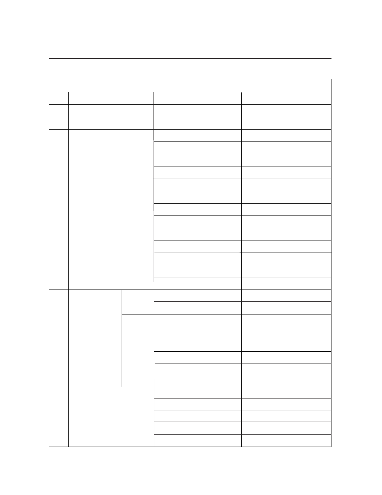
IC101 SAA1300
IC655 TDA7265
ICS801 TNY253P
IC301 LA7845
IC471 TL494CN
ICZ103,104 STK392-040
IC431 MC4558C
IC703 PCF8574P
ICP706 PCF8574P(Option)
IC701,702 TDA6920X
IC705 TC4052BP
ICP705 TEA6422
ICP707 TEA5114A
ICP704 TDA8601
IC706 PCF8591P
IC901 Z9037116PS1
IC902 24C16
IC901 SDA30C264
IC902 27C040
IC903 8574
IC904 24C16
ICT01 SDA5275
ICT02 KM44C4004C
IC06 SDA9361
IC07 CXA2101AQ
IC01 VPC3230D-B2
IC02 SDP9400
IC03 SDS9280
1
2
3
4
5
Block NameNo. IC Location IC Name
Table 2 - 3 IC Line - Up
Reference Information
Samsung Electronics 2-3
2-2 IC Line Up
2-2-1 100Hz
MAIN
SUB
TERMINAL
MICOM
Double Window(D/W)
CS
MODEL
CW
MODEL
MICOM
+
TTX
Reference Information
2-4 Samsung Electronics
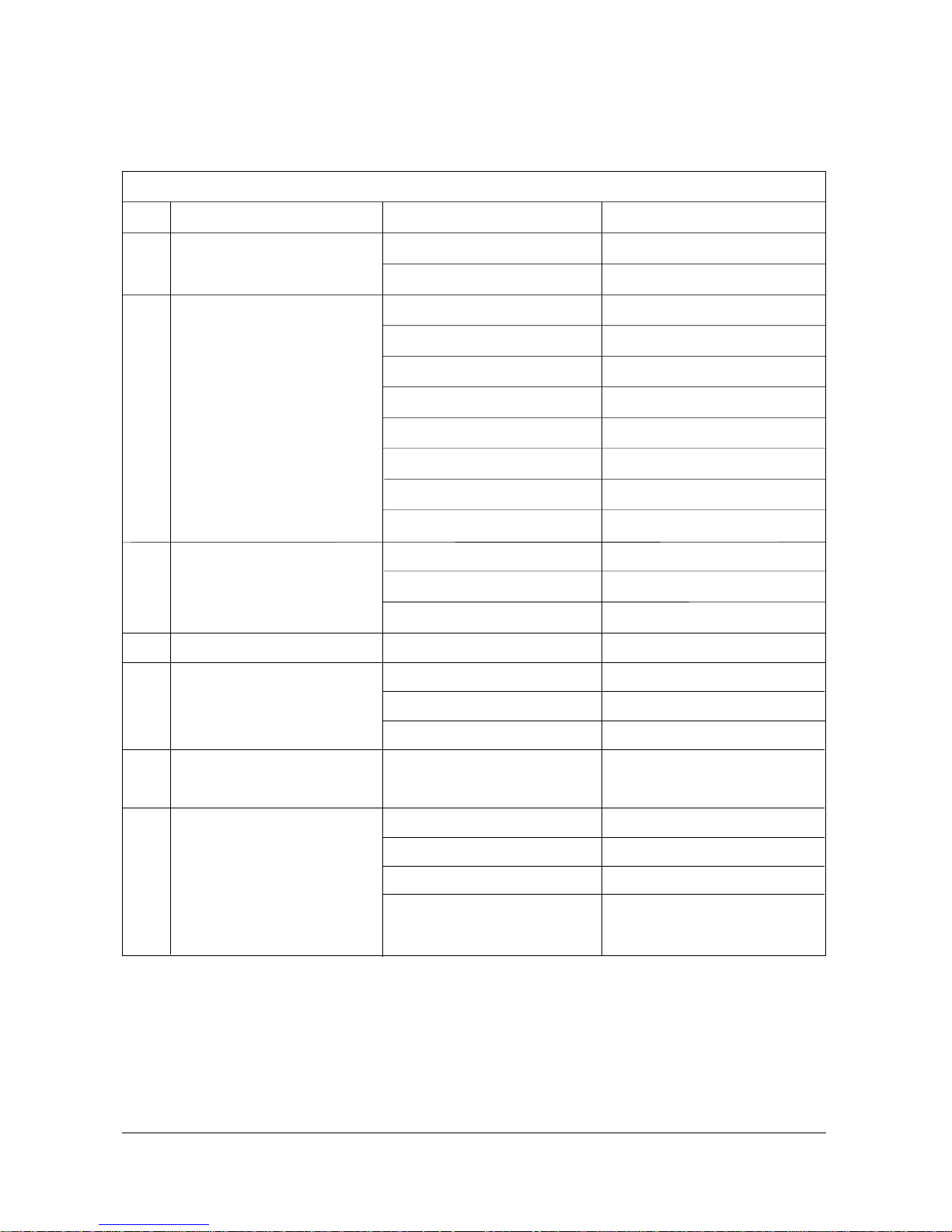
5
6
7
8
9
10
11
Block NameNo. IC Location IC Name
Table 2 - 3 IC Line - Up (Continued)
Double Window(D/W)
Convergence
Sound
CRT
POWER
Sub AMP
Format Converter
PIC01 VPC3230D-B2
PIC02 MS81V04160
IC111,112 CD40668BCM
IC109,110 74HC4066
IC102 74HC4046
IC106,107,108 TL072
IC105 EL2210CS
IC103 TSC87251G2D
IC101 SDC91
IC104 AT82C64
ICD601 MSP3452G-A1
*ICD601 MSP3450G-B6
ICD602,603 TL062
IC501,531,561 TDA6111Q
IC801S STRF6656
IC802 SVD001(OPTION)
IC804 SE11ON
ICS601 TDA 7265
(DOLBLY, SULLOON,OPTION)
IC01 FS401S
IC02 416S11/20
IC03 Z9021106PSC
IC04 24C02
(PC,INPUT,OPTION)
Reference Information
Samsung Electronics 2-5
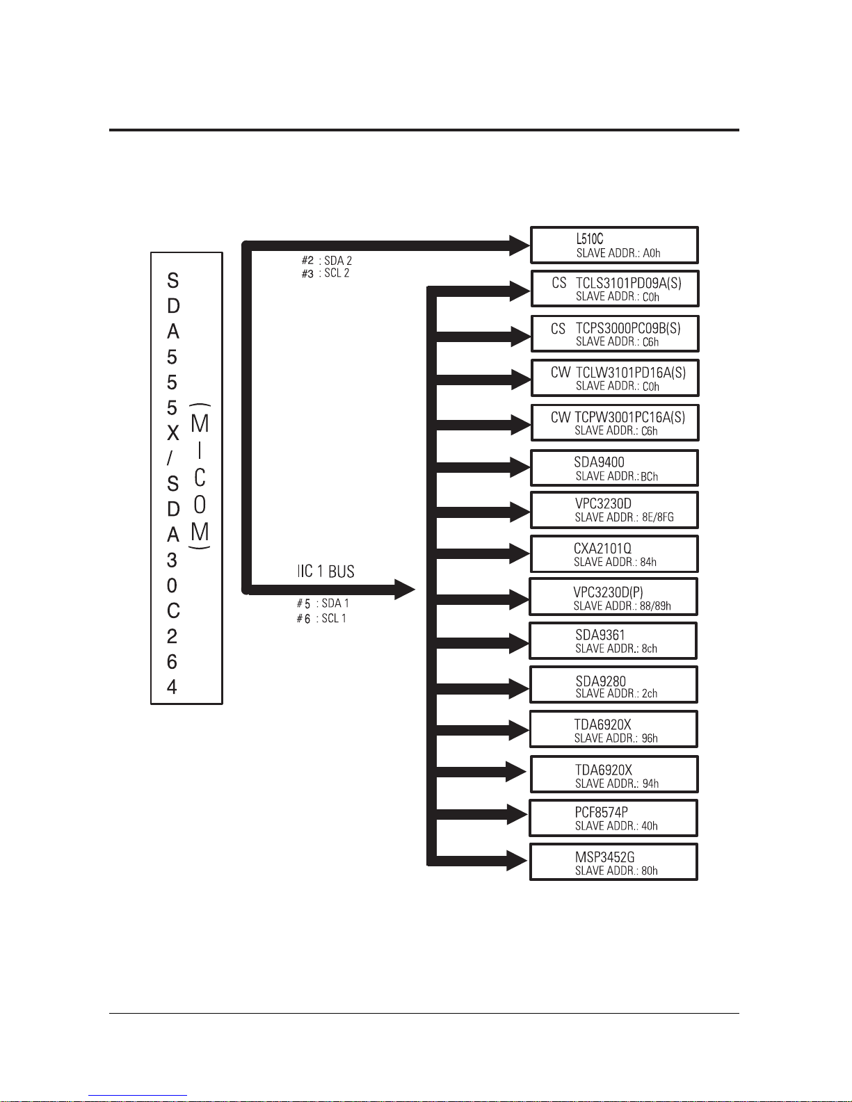
2-3 MICOM IIC BUS LINE -UP

Reference Information
2-6 Samsung Electronics
MENO
Specifications
Samsung Electronics 3-1
3. Specifications
Broadcasting System
Scanning System
Tuning Range
Antenna Impedance
Intermediate Frequency
Sound Output
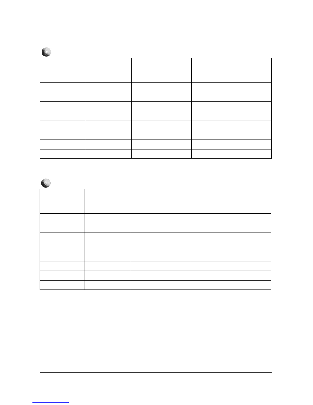
Rated Voltage
White Balance
High Voltage
FUSE
Power Consumption
PAL MULTI
100HZ
VHF : CH2 ~ CH13
UHF : CH14 ~ CH69
Cable : CH1, CH14 ~ 125
75 ohm Unbalanced
Video : 38.9 MHz
Sound : 33.4 MHz
STD : 10W
FULL MAX : 15W
AC220V/AC110~250V/AC180~240V/50Hz
CW
47” Hx : 290 Hy : 285 Y : 8.0
Lx : 290 Ly : 285 Y : 0.3
55” Hx : 290 Hy : 285 Y : 7.5
Lx : 290 Hy : 285 Y : 0.25
CS
43” Hx : 275 Hy : 275 Y : 9.5
Lx : 258 Ly : 255 Y : 0.4
47” Hx : 278 Hy : 275 Y : 8.25
Lx : 268 Hy : 262 Y : 0.29
55” Hx : 276 Hy : 271 Y : 7.9
Lx : 267 Hy : 258 Y : 0.29
29KV
250V/6.3A
CODE NO : 3601-000300
280W
Specifications
3-2 Samsung Electronics
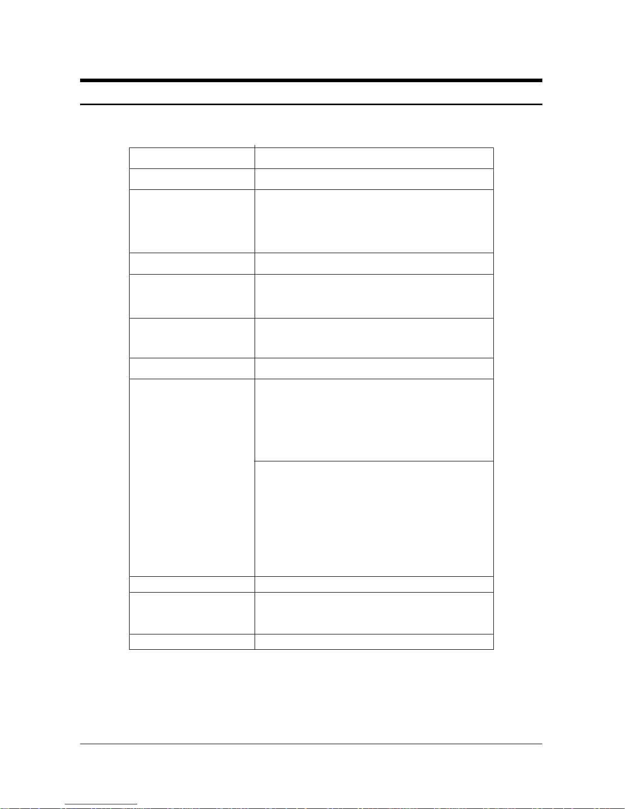
3-1 TV Setup Mode
TV SETUP MENU
H POS LEFT RIGHT
H SCALE SHRINK GROW
V POS DOWN UP
V SCALE SHRINK GROW
RECALL SETTINGS
EXIT
SAVE AND EXIT
MAIN MENU
ZOOM
COMPRESS
FREEZE
SETUP
RESET
EXIT
SETUP MENU
T V S ETUP
COMPUTER SETUP
PICTURE SETUP
EXIT
TV SETUP MENU
H P OS L E F T R I GHT
TV SETUP MENU
H SCA LE SHR I
N
K
GROW
TV SETUP MENU
V P OS DOWN UP
TV SETUP MENU
H POS LEFT RIGHT
H SCALE SHRINK GROW
V P OS DOWN UP
V SCALE SHRINK GROW
RECALL SETTINGS
EXIT
SAVE AND EXIT
TV SETUP M EN U
H POS LEFT RIGHT
H SCALE SHRINK GROW
V POS DOWN UP
V SCALE SHRINK GROW
RECALL SETTINGS
EXIT
SAVE AN D E XI T
SETUP MENU
T V S ETUP
COMPUTER SETUP
PICTURE SETUP
EXIT
TV SETUP MENU
V SCAL E SHRI NK GROW
PC Enter
PC Enter
Switch to External Mode
TV/External Key
Switch to PC Mode
Select Key
Select menu
F.Menu Key
Select TV Setup
CH Down key
Select TV Setup
Volume+ key
Adjust horizontal position (left)
Volume- key
Adjust screen left to balance
Adjust screen left to balance
Adjust horizontal position (right)
Volume - key
Select vertical position adjustment
CH Down key
Adjust screen top to balance
Adjust vertical position (top)
Volume + key
Adjust screen left to balance
Adjust horizontal position (bottom)
Volume+ key
. Save and Exit
CH Down,Volume+ key
Exit
Alignment and Adjustments
Samsung Electronics 3-3
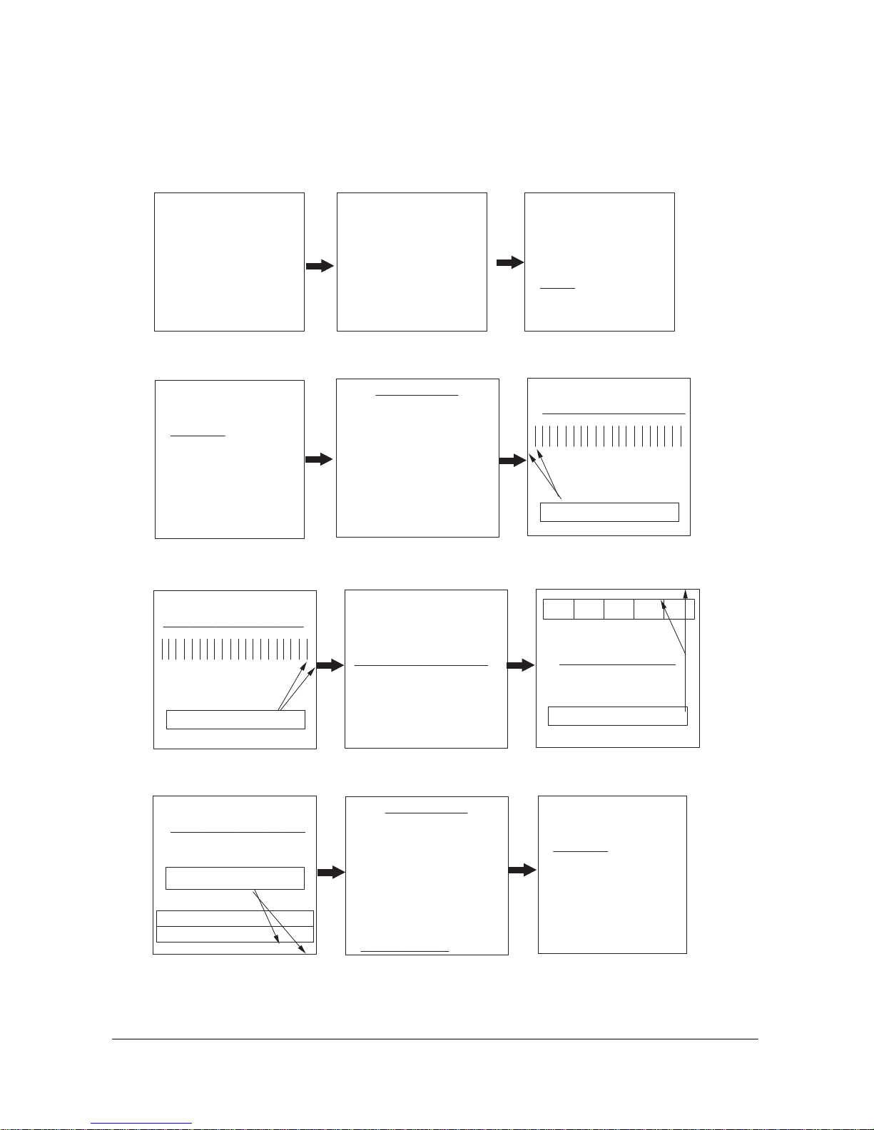
3-2 Picture Setup Mode
1. Adjust four different modes:VGA3 (VGA), VGA (DOS), VESA (SVGA),
VEAS (XGA).
2). Perform the setup for each PC mode and picture setup.
SETUP MENU
TV SETUP
COMPUTER SETUP
P ICTURE S ETUP
EXIT
PICTURE SETUP MENU
BRI GHTNESS
PICTURE SETUP MENU
C OL OR SAT URAT I ON
PI CTURE SETUP MENU
BRIGHTNESS
COLOR SATURETION
FLICKER FILTER
VIDEO FILTER
RECALL SETTINGS
EXIT
SAVE AND EXIT
PICTURE SETUP MENU
F L I CK ER F I L T ER
PICTURE SETUP MENU
BRIGHTNESS
COLOR SATURETION
FLICKER FILTER
VIDEO FILTER
RECALL SETTINGS
EXIT
SAVE AND E XI T
SETUP MENU
TV SETUP
COMPUTER SETUP
P I C TURE SETUP
EXIT
P C
MAIN MENU
ZOOM
COMPRESS
FREEZE
S ETUP
RESET
EXIT
Select Picture Setup
CH Down key
Select Picture Setup
Volume+ key
Set in the bright screen
Adjust brightness
Volume+ key
Set in the bright screen
Adjust color saturation
CH Down, Volume+ key
Set in the bright screen
Adjust flicker filter
CH Down, Volume+ key
Save and Exit
CH Down, Volume- key
Finish picture setup
Volume+ key
Finish Computer Setup
F.Menu key
Exit
Alignment and Adjustments
3-4 Samsung Electronics
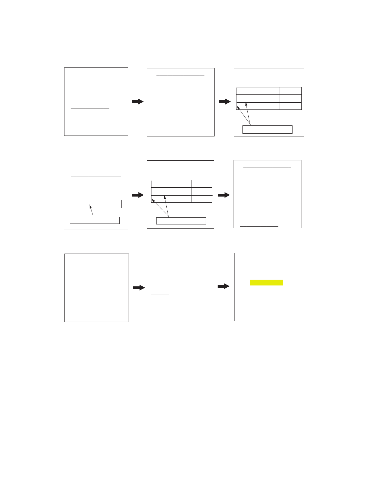
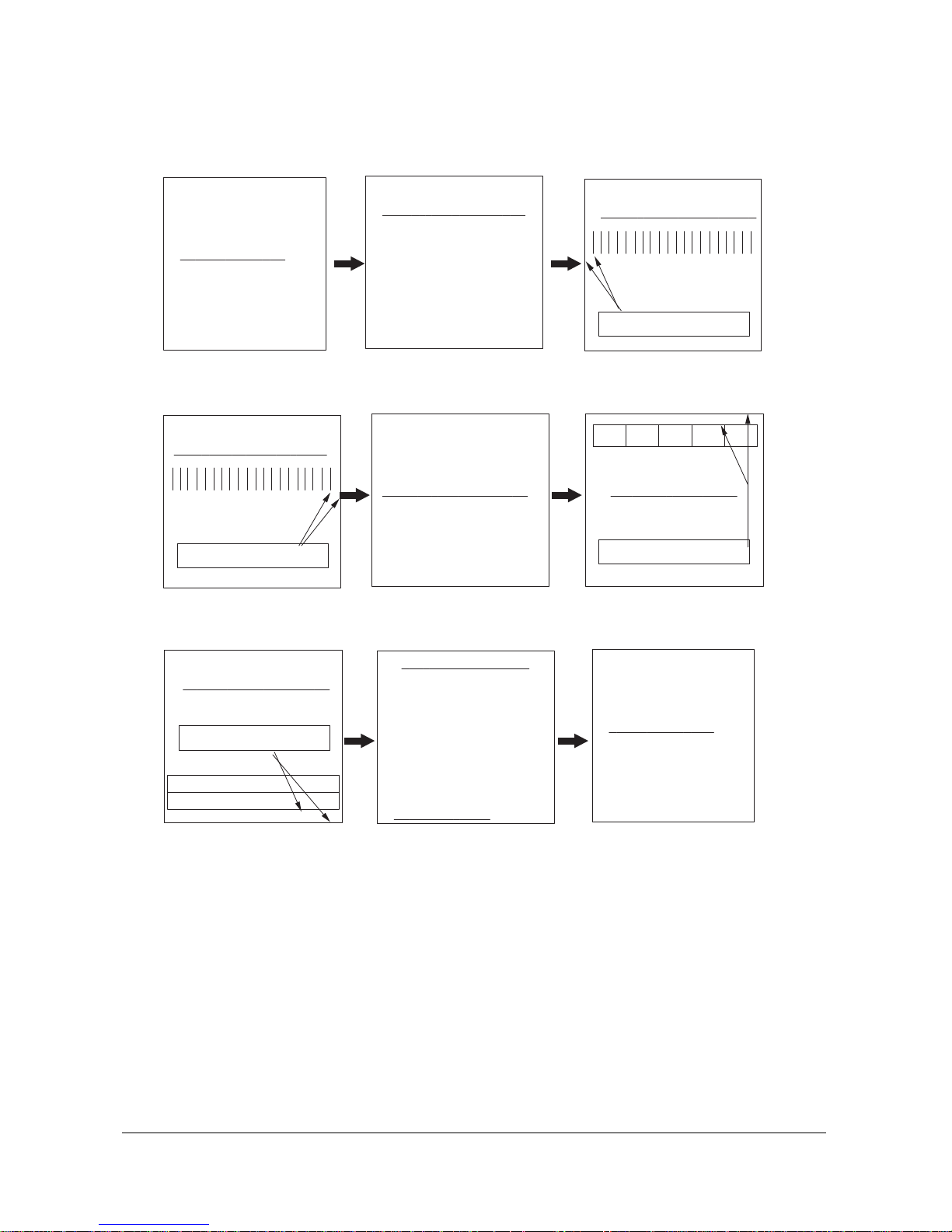
3-3 Picture Setup Mode (computer setup mode only)
1. Adjust four different modes:VGA3 (VGA), VGA (DOS), VESA (SVGA),
VEAS (XGA).
2. Perform the setup for each PC mode and picture setup.
COMPUTER SETUP MENU
H P OS L E F T RI GHT
H SCALE SHRINK GROW
V POS DOWN UP
V SCALE SHRINK GROW
RECALL SETTINGS
EXIT
SAVE AND EXIT
SETUP MENU
TV SETUP
COMP UT ER S ETUP
PICTURE SETUP
EXIT
COMPUTER SETUP MENU
H P OS L E F T R I GHT
COMPUTER SETUP MENU
H SCAL E SHRI NK GROW
COMPUTER SETUP MENU
V P OS DOWN UP
COMPUTER SETUP MENU
H POS LEFT RIGHT
H SCALE SHRINK GROW
V P OS DOWN UP
V SCALE SHRINK GROW
RECALL SETTINGS
EXIT
SAVE AND EXIT
COMPUTER SETUP MENU
H POS LEFT RIGHT
H SCALE SHRINK GROW
V POS DOWN UP
V SCALE SHRINK GROW
RECALL SETTINGS
EXIT
SAVE AND E XI T
SETUP MENU
TV SETUP
COMPUT ER SETUP
PICTURE SETUP
EXIT
COMPUTER SETUP MENU
V SCAL E SHRI NK GROW
Select Computer Setup
CH Down key
Select Computer Setup
Volume+ key
Adjust screen left to balance
Adjust horizontal position (left)
Volume- key
Adjust screen left to balance
Adjust horizontal position (right)
Volume+ key
Select vertical position adjustment
CH Down key
Adjust screen top to balance
Adjust vertical position (top)
Volume+ key
Adjust screen left to balance
Adjust horizontal position (bottom)
Volume+ key
Save and Exit
CH Down, Volume+ key
Exit

Alignment and Adjustments
Samsung Electronics 4-1
4. Alignment and Adjustments
1. Usually, a color TV-VCR needs only slight
touch-up adjustment upon installation. Check
the basic characteristics such as height,
horizontal and vertical sync and focus.
2. Observe the picture for good black and white
details. There should be objectionable color
shading; if color shading is present,
demagnetize, perform purity and convergence
adjustments described below.
3. Use the specified test equipment or its
equivalent.
4. Correct impedance matching is essential.
5. Avoid overload. Excessive signal from a
sweep generator might overload the front-end
of the TV. When inserting signal markers, do
not allow the marker generator to distort test
results.
6. Connect the TV only to an AC power source
with voltage and frequency as specified on the
backcover nameplate.
7. Do not attempt to connect or disconnect any
wires while the TV is turned on. Make sure
that the power cord is disconnected before
replacing any parts.
8. To protect against shock hazard, use an
isolation transformer.
CAUTION : There is no high voltage adjustment on this
chassis. The B+ power supply should be +135 volts (with
full color- bar input and normal picture level).
1. Connect a digital voltmeter to the second
anode of the picture tube.
2. Turn on the TV. Set the Brightness and
Contrast controls to minimum (zero beam
current).
3. Adjust the Brightness and contrast controls to
both extremes. Ensure that the high voltage
does not exceed 32 KV under any conditions.
1. Enter & Concel the Factory Mode
(1) Usual Remote Control
Enter : PICTURE OFF -> DISPLAY KEY ->
MENU KEY -> MUTE KEY -> POWER ON
(Press each remote control key with in 3
seconds).
Cancel : POWER OFF -> ON
(2) Factory Remote Mode
Enter : DISPLAY KEY -> FACTORY KEY
(Press each remote control key with in 3
seconds).
Cancel : POWER OFF -> ON
Press the FACTORY key twice at intervals
of at lease 1 second.
(Enter the AGING Mode once)
(3) Set Value When Entering the Factory Mode
- Picture Mode & Sound Mode are set to
the standard data.
(4) Adjustments
- CH.UP/DOWN Key : Use to select the
item you want.
- VOLUME UP/DOWN Key : Increases or
decreases the value of data.
- MENU Key : Use to save the current set
value in EEPROM and exit to the upper
mode.
- Use the TV/VIDEO Key the conver to the
AV Mode.
4-2 High voltage Check
4-1 General Alignment Instructions
4-3 FACTORY MODE CONTROL
Alignment and Adjustments
4-2 Samsung Electronics
R Drive
B Drive
G Drive
Gamma
R Cutoff
B Cutoff
G Cutoff
Sub Cont
Sub Brt.
Sub Color
Sub Tint
V Peaking
TTX Cont
TTX Bright
PIP Cont
PIP Bright
CG R Contrast
CG G Contrast
CG B Contrast
0 ~ 63
0 ~ 63
0 ~ 63
0 ~15
0 ~ 63
0 ~ 63
0 ~ 63
0 ~15
0 ~ 63
0 ~15
0 ~15
0 ~12
0 ~15
0 ~ 63
0 ~15
0 ~15
0 ~ 63
0 ~ 63
0 ~ 63
4-4 FACTORY MODE MENU
4-4-1 CW MODEL
FUNCTION RANGE
INITIAL DATA
31
31
31
12
31
31
31
7
31
7
7
7
10
10
0
0
40
40
40
Service Mode
Video Adjustment
Y.C-Delay
Deflection normal
Deflection VGA
Option byte
Reset
VIDEO ADJUSTMENT
REMARK
Alignment and Adjustments
Samsung Electronics 4-3
PAL-B/G
PAL-D/K/L
PAL-I
SECAM-B/G
SECAM-D/K/L
NTSC
PAL-AV
SECAM-AV
NTSC-AV
DVD
0 ~15
0 ~15
0 ~15
0 ~15
0 ~15
0 ~15
0 ~15
0 ~15
0 ~15
0 ~15
FUNCTION RANGE
INITIAL DATA
6
8
8
4
6
7
5
4
6
9
Y.C-DELAY
REMARK
P.V-SIZE
P.V-SFT
P.V-LIN
P.S-CORR
P.EW-WTH
P.EW-PBL
P.H-SFT
P.EW-TPZ
P.BOW
P.ANGLE
P.EW-UPCR
P.EW-LOCR
P.HOR-EHT
P.VER-EHT
P.INT. VOL. REF
P.HSYNC DELAY
-128 ~ +127
-128 ~ +127
-128 ~ +127
-128 ~ +127
-128 ~ +127
-128 ~ +127
-64 ~ +63
-128 ~ +127
-128 ~ +127
-128 ~ +127
-128 ~ +127
-128 ~ +127
0 ~ +255
0 ~ +255
-16 ~ +15
-128 ~ +127
FUNCTION RANGE
INITIAL DATA
-40
-39
0
0
+28
-27
-22
0
0
0
0
0
0
0
0
+10
DEFLECTION NORMAL
REMARK
Alignment and Adjustments
4-4 Samsung Electronics
P.PHP
P.PVP
P.PHS
P.PVS
P.CG V-AMP OFFSET
0 ~ 255
0 ~ 255
0 ~15
0 ~15
-128 ~ +127
FUNCTION RANGE
INITIAL DATA
32
32
0
0
+30
DEFLECTION NORMAL
REMARK
LIMIT LEVEL
SYSEM
CLP-MSK
ABL-MODE
ABL-TH
DTV-SYNC
CR-OFFSET1
CB-OFFSET1
CR-OFFSET2
CB-OFFSET2
CTI-LEVEL
R-Y/R
R-Y/B
G-Y/R
G-Y/B
LRGB2-LEVEL
PABL-LEVEL
BLK-BOTTOM
SUB-SHP
SUB-FO
0 ~ 3
0 ~ 3
0 ~ 3
0 ~ 3
0 ~ 3
0 ~ 255
0 ~ 15
0 ~ 15
0 ~ 15
0 ~ 15
0 ~ 3
0 ~ 15
0 ~ 15
0 ~ 15
0 ~ 15
0 ~ 15
0 ~ 15
0 ~ 15
0 ~ 3
0 ~ 3
FUNCTION RANGE
INITIAL DATA
0
1
0
1
1
69
10
10
7
7
1
3
7
15
2
7
15
15
3
2
PICT. IMPROVE
REMARK
Alignment and Adjustments
Samsung Electronics 4-5
PRE-OVER
LT1-LEVEL
VM-LEVEL
VM-DELAY
DC-TRAN
D-PIC
DCTI
BPF-LPF
HPE-CORING
0 ~ 3
0 ~ 3
0 ~ 3
0 ~ 3
0 ~ 3
0 ~ 3
0 ~ 255
0 ~ 255
0 ~ 255
FUNCTION RANGE
INITIAL DATA
3
2
2
3
3
3
8
72
8
PICT. IMPROVE
REMARK
SYSTEM
CR-OFFSET1
CB-OFFSET1
R-Y/R
R-Y/B
G-Y/R
G-Y/B
SUB-SHP
SUB-FO
PRE-OVER
LT1-LEVEL
VM-LEVEL
VM-DELAY
DC-TRAN
D-PIC
0 ~ 3
0 ~ 15
0 ~ 15
0 ~ 15
0 ~ 15
0 ~ 15
0 ~ 15
0 ~ 3
0 ~ 3
0 ~ 3
0 ~ 3
0 ~ 3
0 ~ 3
0 ~ 3
0 ~ 3
FUNCTION RANGE
INITIAL DATA
2
7
9
2
15
7
0
0
0
0
0
0
0
3
3
PICT. IMPROVE
REMARK
Alignment and Adjustments
4-6 Samsung Electronics
CR-OFFSET1
CB-OFFSET1
R-Y/R
R-Y/B
G-Y/R
G-Y/B
0 ~ 15
0 ~ 15
0 ~ 15
0 ~ 15
0 ~ 15
0 ~ 15
FUNCTION RANGE
INITIAL DATA
6
11
2
15
7
0
PICT. IMPRV. SECA
REMARK
CR-OFFSET1
CB-OFFSET1
CT1-LEVEL
DCTI
BPF-LPF
HPE-CORING
0 ~ 15
0 ~ 15
0 ~ 3
0 ~ 255
0 ~ 255
0 ~ 255
FUNCTION RANGE
INITIAL DATA
7
9
1
0
72
8
PICT. IMPRV. DVD
REMARK
SYSTEM
CLP-MASK
DTV-SYNC
CR-OFFSET1
CB-OFFSET1
CTI-LEVEL
R-Y/R
R-Y/B
G-Y/R
0 ~ 3
0 ~ 3
0 ~ 255
0 ~ 15
0 ~ 15
0 ~ 3
0 ~ 15
0 ~ 15
0 ~ 15
FUNCTION RANGE
INITIAL DATA
0
0
0
0
0
0
0
0
0
PICT. IMPRV. 480p
REMARK

Alignment and Adjustments
Samsung Electronics 4-7
G-Y/B
SUB-SHP
SUB-FO
PRE-OVER
LTI-LEVEL
VM-LEVEL
VM-DELAY
DC-TRAN
D-PIC
0 ~ 15
0 ~ 3
0 ~ 3
0 ~ 3
0 ~ 3
0 ~ 3
0 ~ 3
0 ~ 3
0 ~ 3
FUNCTION RANGE
INITIAL DATA
0
0
0
0
0
0
0
0
0
PICT. IMPRV. 480P
REMARK
SYSTEM
CLP-MSK
DTV-SYNC
CR-OFFSET1
CB-OFFSET1
CTI-LEVEL
R-Y/R
R-Y/B
G-Y/R
G-Y/B
SUB-SHP
SIB-FO
PRE-OVER
LTI-LEVEL
VM-LEVEL
VM-DELAY
DC-TRAN
D-PIC
0 ~ 3
0 ~ 3
0 ~ 255
0 ~ 15
0 ~ 15
0 ~ 3
0 ~ 15
0 ~ 15
0 ~ 15
0 ~ 15
0 ~ 15
0 ~ 3
0 ~ 3
0 ~ 3
0 ~ 3
0 ~ 3
0 ~ 3
0 ~ 3
FUNCTION RANGE
INITIAL DATA
0
0
0
0
0
0
0
0
0
0
0
0
0
0
0
0
0
0
PICT. IMPRV. 1080
REMARK
Alignment and Adjustments
4-8 Samsung Electronics
WIDE
EUROPE
ENGLISH
ON
SCART
OFF
ON
ON
ON
CW
ON
ON
OFF
OFF
ON
W-EUROPE
ON
STANDARD
OPTION BYTE
SP55W3HF
SP47W3HF
SIM-826HEW OPTION-BYTE
SP65W3HF REMARK
CRT
LANGUAGE GROUP
LANGUAGE
ATM
SCRT/RCA
VGA
PLUG&PLAY
DOLBY PROLOGIC
PIP
CW/CS
LNA
CHILD-LOCK
HP JACK IDENT
TOP TTX
HIGH DEVIATION
TTX GROUP
GARRIER MUTE
STANDARD
WIDE
EUROPE
ENGLISH
ON
SCART
OFF
ON
ON
ON
CW
ON
ON
OFF
OFF
ON
W-EUROPE
ON
STANDARD
WIDE
EUROPE
ENGLISH
ON
SCART
OFF
ON
ON
ON
CW
ON
ON
OFF
OFF
ON
W-EUROPE
ON
STANDARD
WIDE <--> 4:3
EUROPE <--> ASIA
EIGHTEEN LANGUAGES
ON <--> OFF
SCART <--> RCA
ON <--> OFF
ON <--> OFF
ON <--> OFF
ON <--> OFF
CW <--> CS
ON <--> OFF
ON <--> OFF
ON <--> OFF
ON <--> OFF
ON <--> OFF
E-EUROPE -> RUSSIAN -> ARABIC
-> ICELANDIC -> HEBREW
ON <--> OFF
STANDARD -> SPORT -> MILD
-> NATURAL -> CUSTOM -> NDEN
Alignment and Adjustments
Samsung Electronics 4-9
V Shift
V AMP
V Lin
V SC
V EHT
H AMP
Pin Phase
Pin AMP
Up Corner
Low Corner
H EHT
H Shift
V Angle
V BOW
H Sync Phase
0 ~ 255
0 ~ 255
0 ~ 255
0 ~ 255
0 ~ 255
0 ~ 255
0 ~ 255
0 ~ 255
0 ~ 255
0 ~ 255
0 ~ 255
0 ~ 127
0 ~ 255
0 ~ 255
0 ~ 255
4-4-2 CS MODEL
FUNCTION RANGE
INITIAL DATA
124
134
11
104
0
161
143
70
128
128
0
80
124
128
128
Service Mode
Deflection
Video Adjust1
Video Adjust2
NTSC OFFSET & CG
DW PIP & OTHERS
OPTION
RESET
DEFLECTION
REMARK
Alignment and Adjustments
4-10 Samsung Electronics
VIDEO ADJUST1
0 ~ 63
0 ~ 63
0 ~ 63
0 ~ 63
0 ~ 63
0 ~ 63
0 ~ 63
0 ~ 15
0 ~ 15
0 ~ 15
0 ~ 15
0 ~ 15
0 ~ 15
0 ~ 15
0 ~ 15
0 ~ 8
FUNCTION RANGE
INITIAL DATA
31
31
31
31
31
31
31
7
15
7
3
7
15
2
12
7
REMARK
Red Cutoff
Green Cutoff
Blue Cutoff
Red Drive
Green Drive
Blue Drive
Sub Bright
Sub Contrast
Sub Color
Sut Tint
RYR
RYB
GYR
GYB
Gamma
P.YC Delay
FUNCTION RANGE
INITIAL DATA
VIDEO ADJUST2
REMARK
SUB Sharp
Sharp FO
Prev Over
LT 1
CT1
VM-Level
VM-Delay
DC-TRAN
D Picture
H Width
0 ~ 3
0 ~ 3
0 ~ 3
0 ~ 3
0 ~ 3
0 ~ 3
0 ~ 3
0 ~ 3
0 ~ 3
0 ~ 3
3
2
3
2
1
2
3
3
3
1
Alignment and Adjustments
Samsung Electronics 4-11
FUNCTION RANGE
INITIAL DATA
VIDEO ADJUST2
REMARK
H Time Mask
ABL Mode
ABL TH
TTX Position
TTX Contrast
VSU
RGB Bright
RGB Contrast
Melody Volume
0 ~ 3
0 ~ 3
0 ~ 3
0 ~ 40
0 ~ 255
0 ~ 15
0 ~ 127
0 ~ 63
0 ~ 20
1
1
1
5
200
3
0
24
10
FUNCTION RANGE
INITIAL DATA
NTSC OFFSET & CG
REMARK
Offset V Shift
Offset V AMP
Offset H AMP
Offset H Shift
Cg R Contrast
Cg G Contrast
Cg B Contrast
Cg VAO PAL
Cg VAO NTSC
-64 ~ 63
-64 ~ 63
-64 ~ 63
-64 ~ 63
0 ~ 100
0 ~ 100
0 ~ 100
0 ~ 100
0 ~ 100
2
0
6
4
100
60
10
24
24
Alignment and Adjustments
4-12 Samsung Electronics
PIP VSTR
PIP HSTR
PIP Contrast
DW 43 BCKPOS
DW 43 BCKWID
Cr offset1
Cb offset1
Cr offset2
Cb offset2
SDA9280 LPF
SDA9280 BPF
SDA9280 HPF
SDA9280
CORING/PHACOM
SDA9400 Y NR
SDA9400 C NR
0 ~ 15
0 ~ 15
0 ~ 63
0 ~ 255
0 ~ 255
0 ~ 15
0 ~ 15
0 ~ 15
0 ~ 15
0 ~ 7
0 ~ 15
0 ~ 15
0 ~ 7
0 ~ 15
0 ~ 15
FUNCTION RANGE
INITIAL DATA
VPC3230 0 X 0087
VPC3230 0 X 008A
VPC3230 fp 0 X 0053
SDA9280 0 X 09
SDA9280 0 X 0A
CXA2101 0 X 0F D7:D4
CXA2101 0 X 0F D3:D0
CXA2101 0 X 10 D7:D4
CXA2101 0 X 10 D7:D4
SDA9280 0 X 04 D6:D4
SDA9280 0 X 04 D3:D0
SDA9280 0 X 05 D3:D0
SDA9280 0 X 05 D6:D4
SDA9400 0 X 1E D7:D4
SDA9400 0 X 10 D3:D0
DW PIP & OTHERS
REMARK
ITEM
7
7
48
148
61
10
10
7
7
4
12
10
4
15
15
0 ~ 15
0 ~ 15
0 ~ 63
0 ~ 255
0 ~ 255
0 ~ 15
0 ~ 15
0 ~ 15
0 ~ 15
0 ~ 7
0 ~ 15
0 ~ 15
0 ~ 7
0 ~ 15
0 ~ 15
DOLBY
OFF
OFF
ON
ON
DOUBLE
ON
OPTION BYTE
SP47W3HF
SP43T6HF
SIM-816HC OPTION-BYTE
SP55W3HF REMARK
SOUND
WIDE
SCART1
PC
AUTO FM
PIP
HIGH DEVIATION
DOLBY
OFF
OFF
ON
ON
DOUBLE
ON
DOLBY
OFF
OFF
ON
ON
DOUBLE
ON
DOLBY <--> A2/NICAM <--> V-DOLBY
ON <--> OFF
ON <--> OFF
ON <--> OFF
ON <--> OFF
OFF <--> 1-TUNER <--> 2-TUNER <--> DOUBLE
ON <--> OFF
Alignment and Adjustments
Samsung Electronics 4-13
4-4-3 W3 EU FACTORY DATA
VIDEO ADJUSTMENT
PAL-B/G
PAL-D/K/L
PAL-I
SECAM-B/G
SECAM-D/K/L
NTSC
PAL-AV
SECAM-AV
NTSC-AV
RGB
DVD
YC
SDA9280
SDA9280
SDA9280
SDA9280
SDA9280
-
SDA9280
SDA9280
SDA9280
SDA9280
SDA9280
SDA9280
ITEM CONTROL IC
DEFAULT VALUE
6 (0 ~15)
8 (0 ~15)
8 (0 ~15)
5 (0 ~15)
7 (0 ~15)
-
6 (0 ~15)
4 (0 ~15)
5 (0 ~15)
7 (0 ~15)
9 (0 ~15)
9 (0 ~15)
Y.C DELAY
NO
0
1
2
3
4
5
6
7
8
9
10
11
R Drive
B Drive
G Drive
Gamma
R Cutoff
B Cutoff
G Cutoff
Sub Contrast
Sub Bright
Sub Color
Sub Tint
V Peaking
TTX Contrast
TTX Bright
PIP Contrast
Not used
Cg R Contrast
Cg G Contrast
Cg B Contrast
CXA2101
CXA2101
CXA2101
CXA2101
CXA2101
CXA2101
CXA2101
CXA2101
CXA2101
CXA2101
CXA2101
VPC3230
CXA2101
CXA2101
VPC3230
-
CXA2101
CXA2101
CXA2101
ITEM CONTROL IC
DEFAULT VALUE
29 (0 ~ 63)
36 (0 ~ 63)
32 (0 ~ 63)
8 (0 ~ 15)
31 (0 ~ 63)
15 (0 ~ 63)
32 (0 ~ 63)
15 (0 ~ 63)
28 (0 ~ 63)
9 (0 ~ 63)
9 (0 ~ 63)
8 (0 ~ 63)
7 (0 ~ 63)
0 (0 ~ 63)
43 (0 ~ 63)
-
31 (0 ~ 63)
31 (0 ~ 63)
15 (0 ~ 63)
NO
0
1
2
3
4
5
6
7
8
9
10
11
12
13
14
15
16
17
18
Alignment and Adjustments
4-14 Samsung Electronics
DEFIECTION NORMAL
(When a PAL signal is input)
P.V-Size
P.V-Sft
P. V - L i n
P.V-Corr
P.EW-Wht
P.EW-Pbl
P.H-Sft
P.EW-Tpz
P.Bow
P.Angle
P.EW-UpCr
P.EW-LoCr
P.Hor-EHT
P.Ver-EHT
P.Int.Vol.Ref
P.Hsync Delay
P.PIP H-Position
P.PIP V-Position
P.Not used
P.Not used
P.CG V-amp Offset
SDA9361
SDA9361
SDA9361
SDA9361
SDA9361
SDA9361
SDA9361
SDA9361
SDA9361
SDA9361
SDA9361
SDA9361
SDA9361
SDA9361
SDA9361
SDA9361
VPC3230
VPC3230
-
-
SDA9361
ITEM CONTROL IC
DEFAULT VALUE
-40 (-128 ~ 127)
-34 (-128 ~ 127)
0 (-128 ~ 127)
0 (-128 ~ 127)
44 (-128 ~ 127)
-27 (-128 ~ 127)
0 (-63 ~ 64)
0 (-128 ~ 127)
0 (-128 ~ 127)
0 (-128 ~ 127)
0 (-128 ~ 127)
0 (-128 ~ 127)
0 (0 ~ 255
0 (0 ~ 255)
0 (-16 ~ 15)
10 (-128 ~ 127)
7 (0 ~ 15)
7 (0 ~ 15)
-
-
30 (-128 ~ 127)
NO
0
1
2
3
4
5
6
7
8
9
10
11
12
13
14
15
16
17
18
19
20
DEFIECTION NORMAL
(When a NTSC signal is input)
N.V-Size
N.V-Sft
N.V-Lin
N.V-Corr
N.EW-Wht
N.EW-Pbl
N.H-Sft
N.EW-Tpz
N.Bow
N.Angle
N.EW-UpCr
N.EW-LoCr
N.Hor-EHT
N.Ver-EHT
N.Int.Vol.Ref
N.Hsync Delay
N.PIP H-Position
N.PIP V-Position
N.Not used
N.Not used
N.CG V-amp Offset
SDA9361
SDA9361
SDA9361
SDA9361
SDA9361
SDA9361
SDA9361
SDA9361
SDA9361
SDA9361
SDA9361
SDA9361
SDA9361
SDA9361
SDA9361
SDA9361
VPC3230
VPC3230
-
-
SDA9361
ITEM CONTROL IC
DEFAULT VALUE
-40 (-128 ~ 127)
-34 (-128 ~ 127)
0 (-128 ~ 127)
0 (-128 ~ 127)
44 (-128 ~ 127)
-27 (-128 ~ 127)
0 (-63 ~ 64)
0 (-128 ~ 127)
0 (-128 ~ 127)
0 (-128 ~ 127)
0 (-128 ~ 127)
0 (-128 ~ 127)
0 (0 ~ 255
0 (0 ~ 255)
0 (-16 ~ 15)
10 (-128 ~ 127)
7 (0 ~ 15)
7 (0 ~ 15)
-
-
30 (-128 ~ 127)
NO
0
1
2
3
4
5
6
7
8
9
10
11
12
13
14
15
16
17
18
19
20
Alignment and Adjustments
Samsung Electronics 4-15
Limit Level
System
CLP-MSK
ABL-MODE
ABL-TH
DTV-SYNC
Cr-Offset1
Cb-Offset1
Cr-Offset2
Cb-Offset2
CTI-Level
R-Y/R
R-Y/B
G-Y/R
G-Y/B
LRGB2-Level
PABL-Level
BLK-Bottom
SUB-SHP
SUB-FO
PRE-OVER
LTI-Level
VM-Levle
VM-Delay
DC-TRAN
D-PIC
DCTI
BPF-LPF
HPF-Coing
Luminance signal edge enhancement setting
Signal frequency band switching
Switching of clamping pulse width in various ways
Switching of ABL mode
Adjustment of threshold voltage for ABL-IN input
DTV-Sync
For canceling the offset between CrCb of IN1and SEL IN systems
For canceling the offset between CrCb of IN1and SEL IN systems
For canceling the offset between CrCb of EXT systems
For canceling the offset between CrCb of EXT systems
Color difference signal edge enhancement setting
R-Y axis +(R-Y) component setting
R-Y axis -(B-Y) component setting
G-Y axis -(R-Y) component setting
G-Y axis -(B-Y) component setting
LRGB2 system picture level control
Setting of level detection DC at RGB-OUT of PEAK-ABL
RGB-OUT bottom limiter level control(valid when BLKSW = 1)
Sharpness center control
Sharpness f
o
setting
Presoot to overshoot ratio setting
Luminance signal edge enhancement setting
VM-OUT level control
VM-OUT phase control
Y system DC transmission ratio setting
Dynamic picture(black expansion)control
Digital Color Transition Improvement Control
Luminance Peaking Control
-Gain of band-pass filter -Gain of low-pass filter
Luminance Peaking Control
-Gain of high-pass filter -Gain of high-and band-pass filter
ITEM DESCRIPTION
DEFAULT VALUE
3 (0 ~ 3)
2 (0 ~ 3)
0 (0 ~ 3)
3 (0 ~ 3)
1 (0 ~ 3)
9 (0 ~ 255)
9 (0 ~ 15)
9 (0 ~ 15)
9 (0 ~ 15)
7 (0 ~ 15)
1 (0 ~ 3)
2 (0 ~ 15)
5 (0 ~ 15)
10 (0 ~ 15)
7 (0 ~ 15)
5 (0 ~ 15)
14 (0 ~ 15)
0 (0 ~ 15)
2 (0 ~ 3)
2 (0 ~ 3)
3 (0 ~ 3)
1 (0 ~ 3)
2 (0 ~ 3)
0 (0 ~ 3)
3 (0 ~ 3)
3 (0 ~ 3)
8 (0 ~ 255)
70 (0 ~ 255)
8 (0 ~ 255)
PICT. IMPROVE
CONTROL IC
CXA2101
CXA2101
CXA2101
CXA2101
CXA2101
CXA2101
CXA2101
CXA2101
CXA2101
CXA2101
CXA2101
CXA2101
CXA2101
CXA2101
CXA2101
CXA2101
CXA2101
CXA2101
CXA2101
CXA2101
CXA2101
CXA2101
CXA2101
CXA2101
CXA2101
CXA2101
SDA9280
SDA9280
SDA9280
0
1
2
3
4
5
6
7
8
9
10
11
12
13
14
15
16
17
18
19
20
21
22
23
24
25
26
27
28
NO

Alignment and Adjustments
4-16 Samsung Electronics
NR-Luminance
NR-Chrominace
Luminance Noise Reduction
Chrominance Noise Reduction
ITEM DESCRIPTION
DEFAULT VALUE
8 (0 ~ 14)
6 (0 ~ 14)
PICT. IMPROVE
CONTROL IC
SDA9400
SDA9400
29
30
NO
System
Cr-Offset1
Cb-offset1
R-Y/R
R-Y/B
G-Y/R
G-Y/B
SUB-SHP
SUB-FO
PRE-OVER
LTI-Level
VM-Level
VM-Delay
DC-TRAN
D-PIC
Signal frequency band switching
For canceling the offset between CrCb of IN1 and SEL IN systems
For canceling the offset between CrCb of IN1 and SEL IN systems
R-Y axis +(R-Y) component setting
R-Y axis -(B-Y) component setting
G-Y axis -(R-Y) component setting
G-Y axis -(B-Y) component setting
Sharpness center control
Sharpness f
o
setting
Preshoot to overshoot ratio setting
Luminance signal edge enhancement setting
VM-OUT level control
VM-OUT phase control
Y system DC transmission ratio setting
Dynamic picture(black expansion)control
ITEM DESCRIPTION
DEFAULT VALUE
2 (0 ~ 3)
9 (0 ~ 15)
9 (0 ~ 15)
2 (0 ~ 15)
5 (0 ~ 15)
10 (0 ~ 15)
7 (0 ~ 15)
2 (0 ~ 3)
3 (0 ~ 3)
3 (0 ~ 3)
1 (0 ~ 3)
2 (0 ~ 3)
0 (0 ~ 3)
2 (0 ~ 3)
3 (0 ~ 3)
PICT. IMPROVE. VGA(NOT USED)
CONTROL IC
CXA2101
CXA2101
CXA2101
CXA2101
CXA2101
CXA2101
CXA2101
CXA2101
CXA2101
CXA2101
CXA2101
CXA2101
CXA2101
CXA2101
CXA2101
0
1
2
3
4
5
6
7
8
9
10
11
12
13
14
NO

Alignment and Adjustments
Samsung Electronics 4-17
Cr-Offset1
Cb-offset1
R-Y/R
R-Y/B
G-Y/R
G-Y/B
For canceling the offset between CrCb of IN1 and SEL IN systems
For canceling the offset between CrCb of IN1 and SEL IN systems
R-Y axis +(R-Y) component setting
R-Y axis -(B-Y) component setting
G-Y axis -(R-Y) component setting
G-Y axis -(B-Y) component setting
ITEM DESCRIPTION
DEFAULT VALUE
7 (0 ~ 15)
11 (0 ~ 15)
3 (0 ~ 15)
7 (0 ~ 15)
10 (0 ~ 15)
2 (0 ~ 15)
PICT. IMPROVE. SECAM
CONTROL IC
CXA2101
CXA2101
CXA2101
CXA2101
CXA2101
CXA2101
0
1
2
3
4
5
NO
Cr-Offset1
Cb-offset1
DCT1
R-Y/R
R-Y/B
G-Y/R
G-Y/B
VM-Level
VM-Delay
V-PEAKING
BPF-LPF
HPF-Coring
For canceling the offset between CrCb of IN1 and SEL IN systems
For canceling the offset between CrCb of IN1 and SEL IN systems
Digital Color Transition Improvement Control
R-Y axis +(R-Y) component setting
R-Y axis -(B-Y) component setting
G-Y axis -(R-Y) component setting
G-Y axis -(B-Y) component setting
VM-OUT level control
VM-OUT phase control
Vertical Peaking
Luminance Peaking Control
-Gain of band-pass filter -Gain of low-pass filter
Luminance Peaking Control
-Gain of band-pass filter -Gain of low-pass filter
ITEM DESCRIPTION
DEFAULT VALUE
9 (0 ~ 15)
9 (0 ~ 15)
0 (0 ~ 255)
2 (0 ~ 15)
5 (0 ~ 15)
10 (0 ~ 15)
7 (0 ~ 15)
0 (0 ~ 3)
0 (0 ~ 3)
0 (0 ~ 12)
72 (0 ~ 255)
10 (0 ~ 255)
PICT. IMPROVE. RGB
CONTROL IC
CXA2101
CXA2101
SDA9280
CXA2101
CXA2101
CXA2101
CXA2101
CXA2101
CXA2101
VPC3230
SDA9280
SDA9280
0
1
2
3
4
5
6
7
8
9
10
11
NO

Alignment and Adjustments
4-18 Samsung Electronics
Cr-Offset1
Cb-offset1
DCT1
R-Y/R
R-Y/B
G-Y/R
G-Y/B
VM-Level
VM-Delay
V-PEAKING
BPF-LPF
HPF-Coring
For canceling the offset between CrCb of IN1 and SEL IN systems
For canceling the offset between CrCb of IN1 and SEL IN systems
Digital Color Transition Improvement Control
R-Y axis +(R-Y) component setting
R-Y axis -(B-Y) component setting
G-Y axis -(R-Y) component setting
G-Y axis -(B-Y) component setting
VM-OUT level control
VM-OUT phase control
Vertical Peaking
Luminance Peaking Control
-Gain of band-pass filter -Gain of low-pass filter
Luminance Peaking Control
-Gain of high-pass filter -Gain of high-and band-pass filter
ITEM DESCRIPTION
DEFAULT VALUE
9 (0 ~ 15)
9 (0 ~ 15)
0 (0 ~ 255)
2 (0 ~ 15)
5 (0 ~ 15)
10 (0 ~ 15)
7 (0 ~ 15)
1 (0 ~ 3)
0 (0 ~ 3)
0 (0 ~ 12)
72 (0 ~ 255)
10 (0 ~ 255)
PICT. IMPROVE. DVD
CONTROL IC
CXA2101
CXA2101
SDA9280
CXA2101
CXA2101
CXA2101
CXA2101
CXA2101
CXA2101
VPC3230
SDA9280
SDA9280
0
1
2
3
4
5
6
7
8
9
10
11
NO
Cr-Offset1
Cb-offset1
DCT1
R-Y/R
R-Y/B
G-Y/R
G-Y/B
VM-Level
VM-Delay
V-PEAKING
BPF-LPF
HPF-Coring
For canceling the offset between CrCb of IN1 and SEL IN systems
For canceling the offset between CrCb of IN1 and SEL IN systems
Digital Color Transition Improvement Control
R-Y axis +(R-Y) component setting
R-Y axis -(B-Y) component setting
G-Y axis -(R-Y) component setting
G-Y axis -(B-Y) component setting
VM-OUT level control
VM-OUT phase control
Vertical Peaking
Luminance Peaking Control
-Gain of band-pass filter -Gain of low-pass filter
Luminance Peaking Control
-Gain of high-pass filter -Gain of high-and band-pass filter
ITEM DESCRIPTION
DEFAULT VALUE
9 (0 ~ 15)
9 (0 ~ 15)
0 (0 ~ 255)
2 (0 ~ 15)
5 (0 ~ 15)
10 (0 ~ 15)
7 (0 ~ 15)
1 (0 ~ 3)
0 (0 ~ 3)
0 (0 ~ 12)
72 (0 ~ 255)
10 (0 ~ 255)
PICT. IMPROVE. YC
CONTROL IC
CXA2101
CXA2101
SDA9280
CXA2101
CXA2101
CXA2101
CXA2101
CXA2101
CXA2101
VPC3230
SDA9280
SDA9280
0
1
2
3
4
5
6
7
8
9
10
11
NO

Alignment and Adjustments
Samsung Electronics 4-19
STD Bright
STD Contrast
STC Color
STD Sharpness
STD Tint
STD Colortone
Sports Bright
Sports Contrast
Sports Color
Sports Sharpness
Sports Tint
Sports Colortone
Mild Bright
Mild Contrast
Mild Color
Mild Sharpness
Mild Tint
Mild Colortone
Natural Bright
Natural Contrast
Natural Color
Natural Sharpness
Natural Tint
Natural Colortone
VGA Bright
VGA Contrast
RGB Color
RGB Color_L
RGB Tint
RGB Bri_Cont
Standard Mode Brightness
Standard Mode Contrast
Standard Mode Color
Standard Mode Sharpness
Standard Mode Tint
Standard Mode Colortone
Sports Mode Brightness
Sports Mode Contrast
Sports Mode Color
Sports Mode Sharpness
Sports Mode Tint
Sports Mode Colortone
Mild Mode Brightness
Mild Mode Contrast
Mild Mode Color
Mild Mode Sharpness
Mild Mode Tint
Mild Mode Colortone
Natural Mode Brightness
Natural Mode Contrast
Natural Mode Color
Natural Mode Sharpness
Natural Mode Tint
Natural Mode Colortone
Not used
Not used
RGB Mode Color
RGB Mode Color
RGB Mode Tint
RGB Mode Brightness, Contrast
ITEM DESCRIPTION
DEFAULT VALUE
32 (0 ~ 63)
42 (0 ~ 63)
32 (0 ~ 63)
32 (0 ~ 63)
0 (-31 ~ 31)
0 (0 ~ 4)
32 (0 ~ 63)
51 (0 ~ 63)
32 (0 ~ 63)
38 (0 ~ 63)
0 (-31 ~ 31)
3 (0 ~ 4)
35 (0 ~ 63)
32 (0 ~ 63)
32 (0 ~ 63)
28 (0 ~ 63)
0 (-31 ~ 31)
1 (0 ~ 4)
28 (0 ~ 63)
63 (0 ~ 63)
32 (0 ~ 63)
45 (0 ~ 63)
0 (-31 ~ 31)
3 (0 ~ 4)
32 (0 ~ 63)
32 (0 ~ 63)
5 (0 ~ 255)
209 (0 ~ 255)
0 (0 ~ 255)
27 90 ~ 255)
P.STD CHANGE
CONTROL IC
CXA2101
CXA2101
CXA2101
CXA2101
VPC3230
CXA2101
CXA2101
CXA2101
CXA2101
CXA2101
VPC3230
CXA2101
CXA2101
CXA2101
CXA2101
CXA2101
VPC230
CXA2101
CXA2101
CXA2101
CXA2101
CXA2101
VPC3230
CXA2101
CXA2101
CXA2101
VPC3230
VPC3230
VPC3230
VPC3230
0
1
2
3
4
5
6
7
8
9
10
11
12
13
14
15
16
17
18
19
20
21
22
23
24
25
26
27
28
29
NO
Alignment and Adjustments
4-20 Samsung Electronics
RGB Bri-Cont_L
FB Gain
Slicer Level
RGB Mode Brightness, Contrast
Fast Blanking Signal Gain Control
Slicer Level Control
ITEM DESCRIPTION
DEFAULT VALUE
68 (0 ~ 255)
144 (0 ~ 255)
15 (0 ~ 255)
P.STD CHANGE
CONTROL IC
VPC3230
VPC3230
VPC3230
30
31
32
NO
Side Panel Pos.
Side Panel Width
Side Panel Level
Side Panel B-Y
Side Panel R-Y
Side Panel Position Control
Side Panel Width Control
Side Panel Luminance Control
Side Panel Chrominance Control
Side Panel Chrominance Control
ITEM DESCRIPTION
DEFAULT VALUE
153 (0 ~ 255)
69 (0 ~ 255)
7 (0 ~ 15)
0 (0 ~ 15)
0 (0 ~ 15)
SIDE PANEL ADJUST
CONTROL IC
SDA9280
SDA9280
SDA9280
SDA9280
SDA9280
0
1
2
3
4
NO

Alignment and Adjustments
Samsung Electronics 4-21
4-5 Screen Change (When adjusting I2C Bus Geometric items)
8
PIN PHASE
10 V BOW
5 V ANGLE
4
PIN AMP
2 V LINEARITY
6 V SIZE
3 H SIZE
9 H SHIFT
7 V - S - CORRECTION
1 V SHIFT

Alignment and Adjustments
4-22 Samsung Electronics
4-6 Other Adjustments
4-6-1 Screen Adjustment
1. Warm up the TV for at least 30 minutes.
2. Turn to the Video Mode (No Signal) using a
remote-control.
3. Connect an oscilloscope to RK,GK,BK.
4. Adjust the VR (VR501, VR531, VR561) screen
so that RK, GK, BK pulse is 20Vp-p each.
(Turn the R,G,B VR screen fully
counterclockwise in the area of each flyback
line.)
4-6-2 White Balance Adjustment
1. Select the “STANDARD” video mode.
2. Input 100% white pattern.
3. In the stand-by mode, press the remote-control
keys in the following sequence:
Displsy → Menu → Mute → Power ON
4. Warm up the TV for at least 30 minutes.
5. Input a 10-step signal.
6. R-cut off, B-cut off, and G-cut off by pressing
the Volume +/- keys.
7. Adjust the low light with viewing the dark
side of the screen.
8. Select R-drive, G-drive, and B-drive by
pressing the Volume +/- keys.
9. Adjust the high light with viewing the light
side of the screen.
10. If necessary, redo adjustments 6~9.
11. Press the Menu key to exit.
4-6-3 Sub-Brightness Adjustment
1. Input a sub-brightness adjustment signal.
(TOSHIBA PATTERN)
2. In the stand-by mode, press the remote-control
keys in the following sequence :
Displsy → Menu → Mute → Power ON
3. Select SBT by pressing the Volume +/- keys.
4. Adjust so that the 63 step on the right side of
the screen is not seen (Use the Volume +/keys).
5. Press the Menu key to exit.
4-6-4 High Voltage (29KV) Check
PRECAUTION
1. Input a lion head pattern.
2. Select “STANDARD” video mode.
3. Warm up the TV for at least 10 minutes.
4. Use a 1000:1 probe.
ADJUSTMENT
1. Connect the (+) terminal of the 1000:1 probe to
the high voltage distributor and the (-)
terminal to GND (located on the deflection
board).
2. Adjust RR471S (located on the deflection
board) so that the digital meter indicates
DC 29V ± 0.1V.
4-6-5 F.S. (Fail Safe) Adjustment
Note : The finished product has a well-mounted
VR (RR402S).
If necessary, do the F.S. adjustments in the
following sequence.
1. Use a digital multimeter.
2. Connect the digital multimeter to the JIG pin
(DZ482S) terminals
3. Adjust VR (RR402S) so that the voltage
becomes 2.25V.
4. After the adjustments are complete, be sure to
mount VR (RR402S) correctly.

Alignment and Adjustments
Samsung Electronics 4-23
4-6-6 F.S. (Fail Safe) Circuit Check
Note : The F.S. Circuit check must be performed
after servicing.
1. Turn on the TV.
2. Select the “STANDARD” video mode.
3. Short F/S Test point (located on the SUB PCB).
Then, both sound and picture disappear.
(Note: Even if the shorted terminals are
removed, both sound and
picture do not appear. This proves the F.S.
circuit is working. )
4. To restore both sound and picture, turn off the
TV and reset it after about 30 seconds.
4-6-7 Static Focus Adjustment
PRECAUTION
1. Select the “STANDARD” video mode.
2. Input a crosshatch pattern.
3. Cover the lenses that are not being adjusted.
4. Connect a convergence jig and read data.
5. Adjust the lens for best focus.
(See Fig, 4-1, next page)
STATIC FOCUS (CONTINUED)
Vary the focus pack VR (Red, Blue) on the
front cabinet. Adjust the TV for best possible
focus around the center of the crosshatch
pattern, without losing overall screen balance.
Figure Crosshatch Pattern
Examine these points together.
4-6-8 Lens Focus Adjustment
PRECAUTIONS
1. Do this adjustment after the static focus
adjustment and the tilt adjustment.
2. Select the “STANDARD” video mode.
(Contrast:100, Brightness:50)
3. Input a crosshatch pattern.
ADJUSTMENT
1. Loosen the lens screws.
2. Cover the two lenses that are not being
adjusted.
3. Adjust the lens, observing the color aberration
vertically and horizontally within 3 blocks of
the center of the crosshatch pattern.
4. When the lens is turned clockwise, the color
aberration will change as follows:
Lens Color Aberration Change
R Orange - Crimson
G Blue - Red
B Purple - Green
5. Green lens adjustment:
Set the lens at the point where Blue just
changes to Red. If the color aberration is
irregular throughout the picture screen, adjust
the lens to show Red color aberration
(approximately 1~3 mm area) within a 3-block
grid around the horizontal center-line. If the
color aberration is irregular, adjust the lens as
shown in the diagram below. (Accurate
alignment of Green is important for overall
color quality.)
6. Red lens adjustment
Set the Red lens at the point where Orange
becomes Crimson.
7. Blue lens adjustment
Set the Blue lens at the point where Purple
becomes Green.
P
L1
L2
RED ABERRATION
BLUE ABERRATION
L1, L2 < P
_
Fig. 4-1 Crosshatch Pattern.
Fig. 4-2 Color Aberration
Examine these points together

Alignment and Adjustments
4-24 Samsung Electronics
4-6-9 Horizontal Dynamic Focus Adjustment
PRECAUTION
1. Input a crosshatch pattern.
2. Select the “STANDARD” video mode.
3. Warm up the set for at least 10 minutes.
ADJUSTMENT
1. Cover the Red and Blue lenses.
2. Use a digital multimeter.
3. Connect the '+' terminal of digital multimeter
to D-Focus and the '-' terminal to GND.
4. Adjust L434 located on the sub PCB so that
the digital multimeter indicates
AC690 20Vp-p.(WIDE AC600 20Vp-p)
5. Balance the left and right sides of the dynamic
focus lines.

Alignment and Adjustments
Samsung Electronics 4-25
4-7 SCREEN-JIG
Normal 4:3 Mode
Sc reen Size : X 873, Y 655 (X:378=9*2+ 30*12, Y:440=28*2+ 64*6)
20.79mm 69.29mm
41.68mm
95.27mm
20.79mm
41.68mm
4-7-1 43T6 Normal Mode
4-7-2 54T6 Normal Mode
Norm al 4:3 mode
Sc reen Size : X 1098.4, Y 827.4 (X:378=9*2+ 30*12, Y:440=28*2+ 64*6)
26.15mm 87.17mm
52.65mm
120.35mm
26.15mm
52.65mm

Alignment and Adjustments
4-26 Samsung Electronics
Norm al 4:3 mode
Sc reen Size : X 1045, Y 588 (X:378=9*2+ 30*12, Y:440=28*2+ 64*6)
24.88mm 82.94mm
37.42mm
85.53mm
24.88mm
37.42mm
4-7-3 47W3 Normal Mode
4-7-4 55W3 Normal Mode
Norm al 4:3 mode
Sc reen Size : X 1225, Y 686 (X:378=9*2+ 30*12, Y:440=28*2+ 64*6)
29.17mm 97.22mm
43.65mm
99.78mm
29.17mm
43.65mm

Alignment and Adjustments
Samsung Electronics 4-27
Nor m al m ode
Screen Size : X 1442, Y 838 (X:378=9*2+ 30*12, Y:440=28*2+ 64*6)
34.33mm 114.44mm
53.33mm
121.89mm
34.33mm
53.33mm
4-7-5 65W3 Normal Mode

4-28 Samsung Electronics
Alignment and Adjustments
4-8 Remote Control for Servicing
Power
4-8-1 WESTERN EUROPE

Alignment and Adjustments
Samsung Electronics 4-29
Power
4-8-2 CHINA

Alignment and Adjustments
4-30 Samsung Electronics
4-8-3 KEY Function
1. R-SELECT
Press to select RED color.
2. G-SELECT
Press to select GREEN color.
3. B-SELECT
Press to select BLUE color.
4. R-MUTE
Press to mute RED color.
5. G-MUTE
Press to mute GREEN color.
6. B-MUTE
Press to mute BLUE color.
7. CANCEL KEY
Press to revert to the previous data during the Convergence
Adjustment.
8. TEST/NORMAL
Press to check TV mode in the Convergence Mode.
9. LINE SHIFT
Press to move a line up/down or left/right.
10. FACTORY DATASELECT BUTTON
Press to call the factory default values.
11. H/V DIRECTION SELECT BUTTON
Press to switch the cursor direction horizontally or vertically.
12. SAVE BUTTON
After the Convergence Adjustments are completed, press to save data.
13 EXIT BUTTON
After the Convergence adjustments are completed, press to exit to TV mode.

Alignment and Adjustments
Samsung Electronics 4-31
14. MOVE CURSOR FORWARD
Press to move the cursor right or down.
15. MOVE CURSOR REVERSE JOYSTICK(Option )
Press to move the cursor left or up.
16. CONVERGENCE PICTURE MOVE BUTTON
17. CONVERGENCE MOVE BUTTON
Press to move the convergence left ( ) or right ( ) .
18. CONVERGENCE DATAZERO BUTTON
Press to zero the convergence correction data.
19. INITIAL DATASET BUTTON
20. Data Shift Button Press to transmit data(PAL Mode/NTSC Mode)
Inch (Type)
43” (43T6)
54” (54T6)
62” (62T6)
47”(47W3)
55”(55W3)
65”(65W3)
Model Name
Representative
Model
SP43T6
SP54T6
SP62T6
SP47W3
SP55W3
SP65W3
Basic Data
Number after entring
the Cg-Mode
5-436 (Press in regular order)
5-546 (Press in regular order)
5-626 (Press in regular order)
5-479 (Press in regular order)
5-559 (Press in regular order)
5-659 (Press in regular order)
Screen Display
Discription
White Oval on the background
(white circle)
White Oval on the background
(white border)
White Oval on the background
(white circle)
White Oval on the background
(white border)
Changes when applying Almighty-Cg, Module (How to extract the basic Cg Data)

Alignment and Adjustments
4-32 Samsung Electronics
4-9 Convergence Adjustment
Special Notes
✏ A sensor is attached on the center of each side of the Convergence Mode pattern
(see figure below). The sensors are required for normal Perfect Focus function.
✏ Use a screen jig to do the convergence adjustments correctly (Especially, perform
correct convergence adjustments on the center of each side where a sensor is located.)
✏ Do the convergence adjustments correctly. Otherwise, any Perfect Focus error can
happen.
1. Warm up the TV for a least 30 minutes.
2. Input an PAL Signal.(Use an antenna or AV source.)
Make sure that deflection yoke are properly adjusted so that the center of
Green, Red, Blue pattern is aligned on the center of screen jig.
3. Enter the Convergence Mode by Pressing the remote control keys in the following sequence:
If OSD displayed as shown in figure below, press the key to exit.
Then, redo step 3 to enter the Convergence Mode.
After entering the Convergence Mode, Stand by for about five seconds
before doing the adjustments.

Alignment and Adjustments
Samsung Electronics 4-33

Alignment and Adjustments
4-34 Samsung Electronics

Samsung Electronics 4-35

Alignment and Adjustments
4-36 Samsung Electronics

Alignment and Adjustments
Samsung Electronics 4-37
4-10 MICOM and Pins Voltage
4-10-1 Pin Layout(CW)
17 18 19 20 21 22 23 24 25 26 27 28 29 30 31 32
48
47
46
45
44
43
42
41
40
39
38
37
36
35
34
33
64 63 62 61 60 59 58 57 56 55 54 53 52 51 50 49
P0.4 WP
P0.3 SCL2
P0.2 SDA2
P0.1 SDA1
P0.0 SCL1
P4.1 A18
P4.0 A17
VDD VDDD
VSS VSSD
A2 A2
A1 A1
A0 A0
D3 D3
D2 D2
D4 D4
D1 D1
D1
D2
D3
PROTECT
ST-BY LED1
TIMER LED2
POWER
POWER2
TXD
VSS
VDD
XTAL2
XTAL1
RESET
NC
A16
P3.1
P3.0
P1.6
P1.5
P1.4
P1.3
P1.2
P1.1
P1.0
VSS
VDD
XTAL2
XTAL1
RST
ALE
A16
D5
D0
D6
D7
A10
A4
A11
A5
A6
A8
A7
A13
A12
A14
A15
D5
D0
D6
D7
A10
A4
A11
A5
A6
A8
A7
A13
A12
A14
A15
AMP MUTE
CENTER RESET
BUS-STOP
KEYS1
KEYS2
MAIN AFT
SUB AFT
VSSA
A3
VDDA
M3L CLK
M3L DATA
M3L ENABLE
RXD
IR
P0.5
P0.6
P0.7
P2.3
P2.2
P2.1
P2.0
VSSA
A3
VDDA
P3.7
P3.6
P3.5
P3.4
P3.3
P3.2
SDA30C264

Alignment and Adjustments
4-38 Samsung Electronics
4-10-2 MICOM Pins(CW)
1D1 D1
2D2 D2
3D3 D3
4 PROTECT PROTECT
5 ST-BY LED ST-BY LED
6 TIMER LED TIMER LED
7 POWER POWER
8 POWER2 POWER2
9 TXD TXD
10 VSS VSS
11 VDD VDD
12 XTAL2 XTAL2
13 XTAL1 XTAL1
14 RESET RESET
15 NC NC
16 A16 A16
17 A15 A15
18 A14 A14
19 A12 A12
20 A13 A13
21 A7 A7
22 A8 A8
23 A6 A6
24 A9 A9
25 A5 A5
26 A11 A11
PIN NO. ITEM FUNCTION OUT VOLT

Alignment and Adjustments
Samsung Electronics 4-39
27 A4 A4
28 D10 D10
29 D7 D7
30 D6 D6
31 D0 D0
32 D5 D5
33 D1 D1
34 D4 D4
35 D2 D2
36 D3 D3
37 A0 A0
38 A1 A1
39 A2 A2
40 VSS VSS
41 VDD VDD
42 A17 A17
43 A18 A18
44 SCL1 SCL1
45 SDA1 SDA1
46 SDA2 SDA2
47 SCL2 SCL2
48 WP WP
49 AMP-MUTE AMP-MUTE
50 CENTER-MUTE CENTER-MUTE
51 BUS-STOP BUS-STOP
52 KEY1 KEY1
PIN NO. ITEM FUNCTION OUT VOLT

Alignment and Adjustments
4-40 Samsung Electronics
53 KEY2 KEY2
54 MAIN-AFT MAIN-AFT
55 SUB-AFT SUB-AFT
56 VSS VSS
57 A3 A3
58 VDD VDD
59 M3L CLK M3L CLK
60 M3L DAT M3L DATA
61 M3L ENABLE M3L ENABLE
62 NC NC
63 RXD RXD
64 IR IR
PIN NO. ITEM FUNCTION OUT VOLT

Alignment and Adjustments
Samsung Electronics 4-41
4-10-3 Pin Layout(CS)
W.P
SDA2
SCL2
BUS-STOP
SDA1
SCL1
S-RESET
V-MUTE
VDD 2.5V
GND
VDD 3.3V
CVBS IN
VDD 2.5V
GND
AFT
SUB-AFT
KEY2
KEY1
H-BLK
V-BLK
KEY3
PROTECT
SCONT1
IR-IN
D3
TIMER LED
SCONT 0
POWER 2
POWER
S-MUTE
DVD-CTL
LENTER SPK-MUTE
DTV-ID
DVD-ID
VDD 3.3V
GND
VDD 2.5V
OSD F/B
OSD B
OSD G
OSD R
VDD 2.5V
GND
X-OUT
X-IN
RESET
D1
D2
VDD 3.3V
GND
RTXD
ST-BY LED
1
2
3
4
5
6
7
8
9
10
11
12
13
14
15
16
17
18
19
20
21
22
23
24
25
26
52
51
50
49
48
47
46
45
44
43
42
41
40
39
38
37
36
35
34
33
32
31
30
29
28
27
S
D
A
5
5
5
X

Alignment and Adjustments
4-42 Samsung Electronics
4-10-4 MICOM Pins(CS)
1W.P
2 SDA2
3 SCL2-
4 BUS-STOP I2BUS STOP
5 SDA-1 DATA BUS LINE
6 SCL-1 CLOCK BUS LINE
7 S-RESET SOUND RESET
8 V-MUTE VIDEO SIGNAL MUTE
9 VDD VDD 2.5V
10 GND GND
11 VCC VCC 3.3V
12 CVBS CVBS IN
13 VDD VDD 2.5V
14 GND GND
15 MAIN-AFT MAIN TUNER AFT
16 SUB-AFT SUB AUTO FINE TURNING CONTROL
17 KEY2 KEY SCAN 2
18 KEY1 KEY SCAN 1
19 HSYNC HORIZONTAL SYNC INPUT
20 VSYNC VERTICAL SYNC INPUT
21 KEY3 KEY SCAN 3
22 PROTECT PROTECT PORT
23 S-CONTO SOUND MODE SELECT
24 IR IN REMOCON INPUT
25 D3 CONVERGENCE D3
26 TIMER-LED TIMER LED
PIN NO. ITEM FUNCTION OUT VOLT

Alignment and Adjustments
Samsung Electronics 4-43
27 ST-BY-LEDD LED
28 RXD -
29 GND GND
30 VDD VDD 3.3V
31 D2 DATA BUS LINE
32 D1 CLOCK BUS LINE
33 /RESET RESET
34 XTAL1 XTAL1
35 XTAL2 XTAL2
36 GND GND
37 VDD VDD 2.5V
38 OSD R ON SCREEN DISPLAY RED OUTPUT
39 OSD G ON SCREEN DISPLAY GREEN OUTPUT
40 OSD B ON SCREEN DISPLAY BLUE OUTPUT
41 OSD F-B OSD BLAKING SIGNAL OUTPUT
42 VDD VDD 2.5V
43 GND GND
44 VDD VDD 3.3V
45 DVD-IDENT DVD-IDENT
46 DTV-INENT DTV-IDENT
47 CENTER SPK MUTE
48 MODE SELECT DVD MODE SELECT(480i/480p)
49 AMP-MUTE MAIN AMP MUTE
50 POWER POWERR ON/OFF RELAY CONTROL
51
52 S-CONTO SOUND MODE SELECT
PIN NO. ITEM FUNCTION OUT VOLT

Alignment and Adjustments
4-44 Samsung Electronics
4-10-5 Proscan Module (CS)
1 Pr/R Pr/R INPUT 2.0V
2 Y/G Y/G INPUT 2.0V
3 Pb/B Pb/B INPUT 2.0V
4 FB FAST BLANKING INPUT 0.25V
5 GND GND -
6 HC 5V INPUT -
7 VS1 VS1 INPUT -
8 GND GND -
9 SDA SERIAL DATA LINE 4.7V
10 SCL SERIAL CLOCK LINE 4.8V
11 5V 5V 5V
12 27M OPTION -
13 GND GND GND
14 5V- 5V- 5V-
15 H-OUT HORIZENTAL-OUT N.C
16 V-OUT VERTICAL-OUT N.C
17 SCP -
18 EW EAST WEST OUT 2.2V
19 V-BLK V-BLANKING -
20 ABL ABL INPUT 2.15V
21 AD- VERTICAL DRIVE(-VOLTAGE) 2.95V
22 AD+ VERTICAL DRIVE(+VOLTAGE) 2.90V
23 H-BLK H-BLANKING INPUT -
24 HD H-DRIVE OUT 1.6V
25 GND GND GND
26 PIP-RF -
27 PIP-C -
28 PIP-V/Y -
29 GND GND GND
30 CVBS-Y -
PIN NO. ITEM FUNCTION OUT VOLT

Alignment and Adjustments
Samsung Electronics 4-45
31 CHR CHROMA -
32 GND GND GND
33 PC-R N.C -
34 PC-G N.C -
35 PC-B N.C -
36 PC-H GND GND
37 PC-V OSD-R INPUT -
38 GND OSD-G INPUT -
39 OSD-R OSD-B INPUT -
40 OSD-G BLANK(MICOM OUT) -
41 OSD-B HALF TONE INPUT -
42 YS/YM VIDEO MUTE (V-CHIP ON) 4.72V
43 YS/YM GND GND
44 GND 9V 9V
45 9V D-Pr INPUT -
46 HD-Pr D-Y INPUT -
47 HD-Y D-Pb INPUT -
48 HD-Pb N.C -
49 GND GND GND
50 R-OUT R-OUT -
51 G-OUT G-OUT -
52 B-OUT B-OUT -
53 GND GND GND
54 IK IK OUT 3.65V
55 GND SPOT OUT -
56 GND GND GND
57 VM-Y VM-Y OUT 5.42V
58 YD N.C -
59 GND GND GND
60 CG-SYND CG-SYNC INPUT -
PIN NO. ITEM FUNCTION OUT VOLT

Alignment and Adjustments
4-46 Samsung Electronics
61 CG-B CG-B INPUT -
62 CG-G CG-G INPUT -
63 CG-R CG-R INPUT -
64 GND GND GND
PIN NO. ITEM FUNCTION OUT VOLT

Alignment and Adjustments
Samsung Electronics 4-47
4-10-6 Sound Module
1 GND GND GND
2 GND GND GND
3 GND GND GND
4 S-RESET SOUND RESET -
5 MAIN-L MAIN LEFT OUT -
6 GND GND GND
7 GND GND GND
85V 5V 5V
9 MAIN-R MAIN RIGHT OUT -
10 GND GND GND
11 GND GND GND
12 GND GND GND
13 8V 8V 8V
14 SCL-1 SERIAL CLOCK LINE -
15 GND GND GND
16 SDA-1 SERIAL DATA LINE -
17 CENTER CENTER OUT -
18 GND GND GND
19 GND GNAD GND
20 12V 12V 12V
21 SURROUND SURROUND OUT -
22 GND GND GND
23 GND GND GND
24 S-F1 S-F1(ANT1) -
25 GND GND GND
26 GND GND GND
27 AV4-L-IN AV4 LEFT INPUT -
28 A-MONO-IN A-MONO INPUT -
29 GND GND GND
30 GND GND GND
PIN NO. ITEM FUNCTION OUT VOLT

Alignment and Adjustments
4-48 Samsung Electronics
31 AV4-R-IN AV4 RIGHT INPUT -
32 S-F2 S-F2(ANT2) -
33 GND GND GND
34 GND GND GND
35 GND GND GND
36 GND GND GND
37 EXT-L-IN EXTERNAL LEFT INPUT -
38 H-PHONE-L HEADPHONE LEFT OUT -
39 GND GND GND
40 GND GND GND
41 EXT-R-IN EXTERNAL RIGHT INPUT -
42 H-PHONE-R HEADPHONE RIGHT OUT -
43 GND GND GND
44 GND GND GND
45 GND GND GND
46 GND GND GND
47 AV2-L-IN AV2 LEFT INPUT -
48 MONITOR-L MONITOR OUT -
49 GND GND GND
50 GND GND GND
51 AV2-R-IN AV2 RIGHT INPUT -
52 MONITOR-R MONITOR OUT -
53 GND GND GND
54 GND GND GND
55 GND GND GND
56 GND GND GND
57 AV1-L-IN AV1 LEFT INPUT -
58 AV1-L-OUT AV1 LEFT OUTPUT -
59 GND GND GND
60 GND GND GND
PIN NO. ITEM FUNCTION OUT VOLT

Alignment and Adjustments
Samsung Electronics 4-49
61 AV1-R-IN AV1 RIGHT INPUT -
62 AV1-R-OUT AV1 RIGHT OUT -
63 GND GND GND
64 GND GND GND
PIN NO. ITEM FUNCTION OUT VOLT
Alignment and Adjustments
4-50 Samsung Electronics
4-10-7 CONV-Module
16V 6V 6V
2 GND GND GND
3 FOCUS N.C -
4 GND GND GND
5 D2 SDA -
6 D1 SCL -
7 GND GND GND
8 C-SYNC C-SYNC OUT 4.41V
9 R WHEN TEST PATTERN R OUT -
10 TEST-Y/G WHEN TEST PATTERN G OUT -
11 B WHEN TEST PATTERN B OUT -
12 D3 D3/NT-PAL SEL 0.2V
13 CTRL CTRL -
14 IR INPUT REMOCON 3V
15 COMP COMP VIDEO OUTPUT -
16 GND GND GND
17 GND GND GND
18 GND GND GND
19 BV BLUE VERTICAL OUT -
20 BH BLUE HORIZONTAL OUT -
21 GV GREEN VERTICAL OUT -
22 GH GREEN HORIZONTAL OUT -
23 RV RED VERTICAL OUT -
24 RH RED HORIZONTAL OUT -
25 GND GND GND
26 H-BLK H-BLANKING OUT 0.52V
27 V-BLK V-BLANKING OUT -
28 GND GND GND
29 N.C N.C -
30 -5.4V -5.4V -5.4V
PIN NO. ITEM FUNCTION OUT VOLT

Alignment and Adjustments
Samsung Electronics 4-51
31 5.4V 5.4V 5.4V
32 GND GND GND
PIN NO. ITEM FUNCTION OUT VOLT

Alignment and Adjustments
4-52 Samsung Electronics
MENO

Troubleshooting
Samsung Electronics 5-1
5. Troubleshooting
5-1 Convergence Misaligned
Check the
output voltage and waveform
of CN801, 803, CNZ02 on
the Convergence Board
Normal
Normal
Abnormal
Abnormal
Check CNZ01 out pin
(BZ, BH, RV, RH, GV, GH)
Check the associated
circuitry
Check Convergence
Moudle
1. Check FD802S, FD855S,
FD805S, FD806S On the
Power Board
2. Check the output
from H-BLK, V-BLK
the Main Board

5-2 No Sound
Troubleshooting
5-2 Samsung Electronics
Check if CN601
is inserted
Check IC665
output pins 2, 4
Check IC665
input pin 5
Check IC665
Mute pin 5
Check IC665
output pins 7, 11
Check IC601
input pins 35, 38
Check CNS01
input pins 5, 9
Check IC703
input pins
Check CNS01
output pins 28
Abnormal
Abnormal
Abnormal
normal
normal
normal
normal
Abnormal
Abnormal
Abnormal
Abnormal
Abnormal
normal
normal
normal
normal
Insert CN601
(Connector)
Check FD854S on
the Power Board
Check Speaker
Check the Mute circuit
Check the Control
Check the Control
Check the Sound Module
circuit
Check IC703

Troubleshooting
Samsung Electronics 5-3
5-3 No Raster (Sound OK)
Check Heater
Normal
Normal
Normal
Normal
Normal
Normal
Normal
Normal
Normal
Normal
Normal
Abnormal
Abnormal
Abnormal
Abnormal
Abnormal
Abnormal
Abnormal
Abnormal
Check High Voltage
Check CN501
pins 1, 3, 5
Check
IC501, 531, 561
Check CRT PCB
pin 1
Check Q473
HV-REG
Check
Q473, IC471
Check
Q473, R437A
Check Q472 input
pin "G"(HV-DRIVER)
Check
HV-OUT BLOCK
Check
HV-OUT BLOCK
Check CN501
(Connector)
Check CN501
(Connector)
Check CN01
inpur pins 30, 31
Check CNT02
input pins 19, 21
Check IC02
input pin 24
Check IC701
input pin 8
Check CN01 Check IC701
Check IC02
Check CNT02
Normal
Check CN01

MEMO
5-4 Samsung Electronics

Exploded View & Parts List
Samsung Electronics 6-1
6. Exploded View & Parts List
6-1 SP47W3HFX
No Code No Description;Specification Q’ty S.N.A Remark
1 TAPE-OPP MASKING
2 SPACER-COVER,DUST;W3,PS SHEET,T0.35 1 S.N.A
3 BRACKET-CRT,MAIN;54,SECC,T1.6,-,-,-,- 1
4 GUIDE-FLOW;54J8,J7,ABS,-,-,-,BLK,HB 1 S.N.A
5 HOLDER-SCREEN,R;47H1,ABS HB,GRAY 1 S.N.A
5 HOLDER-SCREEN,TB;W3,W1,ABS HB,L1102,BLK, 2 S.N.A
5 HOLDER-SCREEN,L;47H1,ABS HB,GRAY 1 S.N.A
6 CABINET-BACK,BOT;47W3,HIPS HB,BLK 1
7 CABINET-BACK,TOP;47W3,HIPS HB,BLK,DO 1
8 CABINET-BACK,SIDE;47.55W3,HIPS HB,BLK,DO 2
9 SCREEN-TINT;47W,1070*612,T=0.7,P=0.52 1
10 SCREEN-FRESNEL;47W,-,T2,1072*614,-,-,-,- 1
11 SUN SCREEN-AG;47W,-,T=82%,1072*614*2,-,- 1
12 MIRROR-FRONT;47W3,GLASS ,861*677*421,FSM 1
13 BRACKET-MIRROR;47W3,SECC,T1.0 1 S.N.A
14 ASSY CHASSIS;SP47W3HFX/BWT 1 S.N.A
15 ASSY-C/FRONT,MASK;,HB GRAY,SVM1126 TANTU 1
16 DOOR-RACK;47.55.65W3,HIPS HB,GRAY,SV808P 1
17 ASSY-CABINET,WOOD;,WOOD,CIS,47W3 1 S.N.A
18 ASSY SUB-PCB,A/V TERMINAL;W3,J52A,RUSSIA 1
19 ASSY-C/FRONT,BOT;,HB GRAY,SV808P+SVM1126 1
20 ASSY-CENTER,SPK;,W3

Exploded View & Parts List
6-2 Samsung Electronics
6-2 SP55W3HFX
No Code No Description;Specification Q’ty S.N.A Remark
1 ASSY-C/FRONT,MASK;,HIPS HB,GRAY SVM1126 1
2 ASSY-C/FRONT,BOT;,HIPS HB,GRAY SV808P+SV 1
3 ASSY-DOOR,RACK;,HB GRAY,SV808P+SVM1126,W 1
4 ASSY-CENTER,SPK;,W3 1
5 SUN SCREEN-AG;55W,-,T=82%,1251*712*2,-,- 1
6 SCREEN-FRESNEL;55W,-,T2,1251*712,-,-,-,- 1
8 ASSY-CABINET,WOOD;,WOOD M-EAST,55W3 1
9 CABINET-BACK,SIDE;47.55W3,HIPS HB,BLK,DO 2
10 HOLDER-SCREEN,TB;55W3,ABS HB,L1282,BLK 2
10 HOLDER-SCREEN,L;55W3,ABS HB,BLK 1
10 HOLDER-SCREEN,R;55W3,ABS HB,BLK 1
11 ASSY SUB-PCB,A/V FRONT;SP47W3HFX/XEG,J52 1
12 ASSY CPT-B;P16LSG03BMB,55,+380MGSSM-100 1
13 SPACER-COVER,DUST;W3,PS SHEET,T0.35 1
14 MIRROR-FRONT;55W9,FSM,1027*799*540 1
15 BRACKET-FRAME,MIRROR L;55W9,SECC,T1.6,BL 1
16 BRACKET-FRAME,MIRROR R;55W9,SECC,T1.6,BL 1
17 SPACER-MIRROR,TOP;50J6,PVC HB,BLK,L1020 1
18 SPACER-MIRROR,L;50J6,PVC HB,BLK,L1020 1
19 SPACER-MIRROR,BOT;50J6,PVC HB,L799,BLK 1
20 SPACER-MIRROR,R;50J6,PVC HB,BLK,L1020 1
21 BRACKET-MIRROR,BOT;55W9,SECC,T1.0 1
22 BRACKET-MIRROR,TOP;55W9,SECC,T1.0,BLK 1
23 CABINET BACK-TOP;55W3,PS SHEET,T4.0 1
24 CABINET BACK-BOT;55W3,HIPS HB,BLK 1
25 ASSY CHASSIS;SP55W3HFX/BWT 1

1 AA59-00220A REMOCON;,TM63,SHARK,51,L/GRAY,EAST ASI
1 AA94-03599A ASSY CRT-(R);P16LSG03RJA,+380MG,7,PCL621
1 AA94-03600A ASSY CRT-(G);P16LSG03HKA,+380MG,7,PCL621
1 AA94-03601A ASSY CRT-(B);P16LSG03BMB,+380MG,7,PCL621
1 0203-001329 TAPE-OPP MASKING;ANT-300P,T0.07,W15.0,L5
1 AA02-00022A TAPE ETC;SESA,T0.3,75,132,BLK
1 6005-001004 SCREW-WOOD;HH,+,M4,L27,BLK,SWRCH18A
1 6001-000137 SCREW-MACHINE;BH,+,M3,L8,ZPC(YEL),SM20C,
1 6003-001019 SCREW-TAPTITE;RH,+,B,M4,L12,ZPC(BLK),SWR
1 6003-001026 SCREW-TAPTITE;RH,+,B,M4,L15,ZPC(BLK)
1 6005-001003 SCREW-WOOD;HH,+,M4,L19,ZPC(BLK),SWRCH18A
1 6005-001005 SCREW-WOOD;HH,+,M4.0,L19,NI PLT,SWRCH18A
1 6006-001094 SCREW-ASS’Y WOOD;WW,HH,+,M7,L32,ZPC(YEL)
1 AA60-00132A SPACER-COVER,DUST;DP,W3,T0.5,60-00123B
1 AA60-10011A SCREW-TAPTITE;-,SWRCH18A,M4,L12,HH,+,PC,
1 AA61-00617B BRACKET-CRT,MAIN;DP,54J7,AA61-00475B
1 AA61-00859A PLATE-CENTER,SPK;W3,WOOD
1 AA91-00921A ASSY-HOLDER,MIRROR;,HIPS HB BLK,47W3
1 AA91-00921B ASSY-HOLDER,MIRROR;,HIPS HB BLK,47W3
1 AA61-00972B HOLDER-SCREEN,R;47H1,ABS HB,GRAY
1 AA61-00049B HOLDER-BOX;-,PP,-,-,-,NTR,V0,AA61-20285A
1 AA73-00005B RUBBER-CAP;FLAT,PRJ,SILICONE RUBBER,WHIT
1 AA63-10007C BAND-PP;-,-,-,W18,-,CLEAR,1G
1 AA63-60131A SPACER-FELT;SVP403J,FELT,-,-,-,BLK,T0.5,
1 AA63-70002A SHEET;-,PE FOAM,T1.0,-,-,-,50G
1 AA64-01395Q INLAY-TERMINAL;47W3,PS SHEET,T0.5,BLK,J5
1 AA64-02336A CABINET-BACK,BOT;W3,HIPS,V0,BLK
1 AA64-02074D INLAY-SPEAKER;T6,W3,PS SHEET,T0.5,J52A P
1 AA64-02224B CABINET-BACK,TOP;DP,47W3,HIPS HB,BLK,641 AA64-02225B CABINET-BACK,SIDE;DP,47.55W3,HIPS HB,BLK
1 AA64-60449B INLAY-COVER;SP-434JMF,PS,T0.5,149.3X69.5
1 AA65-30008A CLAMP-CORD;-,PE,HB,-,BLK,1 AA67-00196A AA95-00714B70*612,T=0.73,P=0.52
1 AA67-00119B SCREEN-FRESNEL;47W,-,T2,1072*6
1 AA67-00136A SUN SCREEN-AG;47W,-,T=82%,1072*614*2,-,1 AA67-00165A MIRROR-FRONT;47W3,GLASS ,861*677*421,FS
1 AA69-00744L BAG-SHEET;-,HDPE PE FOAM,T0.015,W1650,H1
1 AA69-01227B CUSHION SET;47W3,EPS C=0.02
1 AA69-01298A PACKING CASE-IN;47W3,CB H-3 AB,YEL,1207
1 AA69-01299E PACKING CASE-OUT;47W3,CB H-3 AB,YEL,SESA
1 AA73-00008A RUBBER-SHEET;47W3,MBR,18*50,T2.0
1 AA91-00773A ASSY-BRACKER,MIRROR;DP,91-00751A 19.5KG,
1 AA91-03555A ASSY CHASSIS;SP47W3HFS/XEF
1 AA94-11168D ASSY PCB MISC-V/M;DP,PCL545R,P54A
1 AA95-01841C ASSY SUB-PCB,SENSOR;DP,PCL545R,P54A,AA95
1 AA95-01790K ASSY SUB-PCB,A/V TERMINAL;DP,SP55W3HF,J5
1 AA95-01847G ASSY SUB-PCB,SUB AMP;DP,SP55W3HF,J52AAA9
1 AA95-01785E ASSY SUB-PCB,A/V FRONT;DP,SP55W3HF,J52A3
1 AA94-11166E ASSY PCB MISC-CRT;DP,SP47W3HF,J52A
1 AA95-01753D ASSY SUB-PCB CONTROL;DP,SP47W3HF,J52A,AA
1 AA96-20130A ASSY-POWER,CORD;-,CP2/NO(4.0R),H/C150,KJ
1 0201-001059 ADHESIVE-SIL;#9590,WHT,-,CARTRIGE
1 AA26-00101A TRANS FBT;FWZ50A001E/FFA97513B,12KV,5P,1 AA39-20577B LEAD CONNECTOR ASSY;P54A/SVP-55W3HD,UL16
1 AA40-00094A TUNER;TCLW3101PD16A(S),PAL/SECAM,181
1 AA40-00095A TUNER;TCPW3001PC16A(S),PAL/SECAM,181
1 AA59-00171A MODULE-FOCUS,PACK;SVP-5200,S300-P3,-,-,1 AA63-10002A BAND-TIE;-,NYLON66 V2,-,-,L100,NTR,1 AA65-30013A CLAMP-WIRE;-,NYLON-6
1 AA65-30018A CLAMP-WIRE;DONG-A,NYLON-66,-,-,-,DATL-60
1 AA65-30104B CLAMP-WIRE;ALL MODEL,NYLON 66,V2,-,BLK,W
1 AA68-02302A MANUAL USERS;W3/T6,BULGARIA,W/P100(G),1,
1 AA68-50509A LABEL-BOX;A/P 90(G),ALL MODEL,-,WHT,L250
1 AA68-00344A LABEL-TRANSFER BOX;-,TF-53B
1 AA68-00341A LABEL-RATING;-,TF53B5DF,-,SILVER,5
1 AC68-00347A LABEL-TRANSFER RATING;ALTA RESISTENCI
1 AA68-00340A LABEL-WARRANTY;-,-,-,WHT,75MM,20
1 AA68-00345A LABEL-TRANSFER WARRANTY;-,TF-53B5D
1 AA61-20126A HOLDER-LEG;-,ABS,-,-,-,BLK,
1 AA69-30009C BAG-SHEET;LDPE,T0.08,W150,L120,-,-,1 4301-000115 BATTERY-ALKALINE;1.5V,750mAH,AAA,10.
1 AA39-40001B CABLE-RCA;,1500MM
1 AA69-00862A BAG PE;-,HDPE PE FOAM,T0.03,W400,H240
1 AA68-50523A LABEL-BACK,DOLBY;A/P 100(G),CW764AHD,DOL
1 AA39-30007B IF-CABLE;-,T,150mm,1365#26
1 0203-000402 TAPE-KRAFT;KRAFT,T0.17,W18,L50,BLK
1 6003-001023 SCREW-TAPTITE;RWH,+,B,M3,L10,ZPC(YEL),SW
1 6003-001022 SCREW-TAPTITE;RH,+,B,M3,L12,ZPC(BLK),SWR
1 AA68-02155A LABEL-POP,RACK;W3 ,PASCAL, ,REMOVABLE
1 AA68-02156A LABEL-POP,AGS;W3 ,PASCAL, ,REMOVABLE
1 AA68-02415A CARD-RTF;COLORIT 54 CREMA,MOJO80G,SPA,A
1 BP65-00001A TERMINAL-BOARD,ANT;,DP,42W5,AA65-00021A
1 AA69-01874A PALLET;ALL MODEL,WOOD,800,1250,120
ASSY-C/FRONT,BOT
1 AA91-00775H ASSY-C/FRONT,BOT;DP,64-02063P,47W3
2 AA64-02063C CABINET-FRONT,BOT;47W3,,HIPS HB,GRAY,SV8
2 AA61-00791B HOLDER-FRONT,BOT;W3,ABS HB,L40,BLK,D
2 AA61-01068A HOLDER-CABINET,BOT(B);W3,ABS HB,L40,BLK,
2 AA64-02205B BADGE-DECORATION;W3,NI+AL FORGING+NI,RS
2 BP96-00127A ASSY COVER P-HOLDER,CONTROL;DP,W3,ABS HB
2 6003-001026 SCREW-TAPTITE;RH,+,B,M4,L15,ZPC(BLK)
2 AA61-00785B GUIDE-KNOB,POWER;W3,ABS HB ,BLK,C
2 AA61-00786B HOLDER-CONTROL;W3,ABS HB,WHT,SV104M
2 AA61-60003J SPRING-CS;-,SUS304,-,-,OD6,
2 AA64-02080B KNOB POWER;W3,ABS HB WHT,SV104M
2 AA64-02081B KNOB-CH,VOL;W3,ABS HB,BLK,CH
2 AA64-02082B WINDOW-RMC,LED;W3,PC,CLEAR
ASSY-DOOR,RACK
1 AA91-00774E ASSY-DOOR,RACK;DP,W3,HB GRAY,64-02066
2 AA64-02066C DOOR-RACK;47.55.65W3,HIPS HB,GRAY,SV808
2 AA64-02206B WINDOW-DOOR;W3,GLASS,T3.0,BR
2 AA91-00758A ASSY-HINGE,DOOR(R);SPRING,SECC T1.6 W3,W
2 AA91-00749A ASSY-HINGE,DOOR(L);,NO-SPRING SECC T1.6,
2 BP61-00128A BRACKET-DOOR;DP,47W3,AA61-00856B
2 AA61-00782B BRACKET-MAGNET;W3,SPC,T2.0,FZW
2 AA73-00007B RUBBER-CAP;W3,MBR,GRAY,60
2 6003-001019 SCREW-TAPTITE;RH,+,B,M4,L12,ZPC(BLK),SWR
ASSY-C/FRONT,MASK
1 AA91-00824D ASSY-C/FRONT,MASK;DP,HB GRAY,02058C 22K
2 AA64-02058C CABINET-FRONT,MASK;47W3,HIPS HB,GRAY,SVM
2 AA64-02211B BADGE-BRAND;72MM,AL FORGING,SVM1-126PS,S
2 AA63-00063A SPACER-DUAL,LOCK;#400,-,-,19X19,SVP-614J
2 AA61-00974A HOLDER-MASK;47H1,HIPS HB,BLK
ASSY-CABINET,WOOD
1 AA90-00970A ASSY-CABINET,WOOD;SP47W3HFS/XEF,47W3
2 AA91-00759E ASSY-CABINET,WOOD;,WOOD XSA,47W3
2 AA64-02207A CABINET-WOOD;47W3,WOOD
Electrical Parts List
Samsung Electronics 7-1
Level Loc. No. Code No. Description ; Specification Remark Level Loc. No. Code No. Description ; Specification Remark
7. Electrical Parts List
7-1 SP47W3HFX/BOB

2 AA60-00078B SPACER-DUAL,LOCK;W3,#250,19*40
2 AA60-10051A SCREW-WOOD;-,SWRCH18A,M4,L16,PH,+,-,-,ZP
2 AA60-10051B SCREW-WOOD;-,SWRCH18A,M3.5,L11,RH,+,-,-,
2 AA61-00094C HOLDER-RAIL;PCJ533R,ABS,-,-,-,BLK,HB,480
2 AA61-00097A HOLDER-WIRE;-,NYLON 6/6,-,-,-,NTR,2 AA61-00723A HOLDER-PIN,DABO;PRJT,WOODEN NAIL,OD6XL20
2 AA61-00507B HOLDER-CABINET,WOOD;43,54,62J8,ABS,-,-,2 BP61-00075A HOLDER-JERSEY,ASSY;W3,ABS V0,GRAY,63-000
2 AA61-00616B HOLDER-CRT,MAIN;54J7,DP,-,-,-,-,AA61-005
2 AA61-01117A HOLDER-SENSOR,SIDE;W3,ABS HB,G3676,SIDE
2 AA61-00864A HOLDER-PCB;W3,HIPS,V0,BLK
2 AA61-00894B HOLDER-SCREEN,TOP;W3,DP,L1082,BLK,61-008
2 AA61-00894A HOLDER-SCREEN,TOP;W3,DP,L1102,BLK,61-008
2 AA61-00458B CASTER;-,TP4020-05 PLY,-,OH56,-,-,SR4
2 AA61-00865A HOLDER-SCREEN,RL;W3,DP,61-00788B 16.2KG
2 BP61-00087A RAIL-DOOR,R;W3,ABS HB,BLK
2 BP61-00087B RAIL-DOOR,L;W3,ABS HB,BLK
2 AA61-00857B BRACKET-NUT,INSERT;W3,M3 ZN
2 AA61-00858B BRACKET-FRAME;W3,SECC,T2.0
2 AA61-10247A BRACKET-FOCUS;S46DS,SECC,T1.0,-,-,-,2 AA63-00348B COVER-DUCT;54,62J8,HIPS,-,HB,BLK,-,2 AA65-00014C CLAMP-WIRE;54J9,SINGLE NYLON,-,-,BLK,2 AA91-00750A ASSY-MAGNET,PUSH;,MAGNET,W3
2 AA96-00753A ASSY SPEAKER;,3001-001107)
3 3001-000151 SPEAKER;20W,8ohm,92dB,130Hz
3 3001-001107 SPEAKER;20W,8ohm,95dB,1300Hz
3 3001-001134 SPEAKER;30W,8ohm,93dB,60Hz
3 AA39-00086A LEAD CONNECTOR-ASSY;,2.2UF,REC,REC,200MM
3 AA39-00287A LEAD CONNECTOR ASSY;PCL54RX,UL2547#26,UL
3 AA39-20609A LEAD CONNECTOR-ASSY;,2P,SMH250-02,REC,40
3 AA98-00049B ASSY-LEAD,CON;-,LEAD-CON,CORE,AA39-20505
2 6005-001006 SCREW-WOOD;FH,+,M3,L15.0,ZPC(BLK),SWRCH1
2 AA60-10050Y SCREW-WOOD;-,SWRCH18A,M4,L40,FH,+,-,-,ZP
2 AA61-00999A HOLDER-DUAL,LOCK;W3,W1,ABS HB,BLK
2 AA61-20219A HOLDER-FRONT,BOT,E;,ABS,HB,L40,BLK
2 AA61-01070A HOLDER-CABINET,BOT(D);W3,ABS HB,L990,BLK
2 AA61-00975A HOLDER-CABINET,BOT-F;W3,ABS HB,GRAY
2 BP63-00001A SHEET-EMI;55W3,PS V2+AL LAMI,T0.35,350*
Electrical Parts List
7-2 Samsung Electronics
Level Loc. No. Code No. Description ; Specification Remark Level Loc. No. Code No. Description ; Specification Remark

1 AA59-00220A REMOCON;,TM63,SHARK,51,L/GRAY,EAST ASI
1 AA94-03599A ASSY CRT-(R);P16LSG03RJA,+380MG,7,PCL621
1 AA94-03600A ASSY CRT-(G);P16LSG03HKA,+380MG,7,PCL621
1 AA94-03601A ASSY CRT-(B);P16LSG03BMB,+380MG,7,PCL621
1 0203-001329 TAPE-OPP MASKING;ANT-300P,T0.07,W15.0,L5
1 AA02-00022A TAPE ETC;SESA,T0.3,75,132,BLK
1 6005-001004 SCREW-WOOD;HH,+,M4,L27,BLK,SWRCH18A
1 6001-000137 SCREW-MACHINE;BH,+,M3,L8,ZPC(YEL),SM20C,
1 6003-001019 SCREW-TAPTITE;RH,+,B,M4,L12,ZPC(BLK),SWR
1 6003-001026 SCREW-TAPTITE;RH,+,B,M4,L15,ZPC(BLK)
1 6005-001003 SCREW-WOOD;HH,+,M4,L19,ZPC(BLK),SWRCH18A
1 6005-001005 SCREW-WOOD;HH,+,M4.0,L19,NI PLT,SWRCH18A
1 6006-001094 SCREW-ASS’Y WOOD;WW,HH,+,M7,L32,ZPC(YEL)
1 AA60-00132A SPACER-COVER,DUST;DP,W3,T0.5,60-00123B
1 AA60-10011A SCREW-TAPTITE;-,SWRCH18A,M4,L12,HH,+,PC,
1 AA61-00617B BRACKET-CRT,MAIN;DP,54J7,AA61-00475B
1 AA61-00859A PLATE-CENTER,SPK;W3,WOOD
1 AA91-00921A ASSY-HOLDER,MIRROR;,HIPS HB BLK,47W3
1 AA91-00921B ASSY-HOLDER,MIRROR;,HIPS HB BLK,47W3
1 AA61-00972B HOLDER-SCREEN,R;47H1,ABS HB,GRAY
1 AA61-00049B HOLDER-BOX;-,PP,-,-,-,NTR,V0,AA61-20285A
1 AA73-00005B RUBBER-CAP;FLAT,PRJ,SILICONE RUBBER,WHIT
1 AA63-10007C BAND-PP;-,-,-,W18,-,CLEAR,1G
1 AA63-60131A SPACER-FELT;SVP403J,FELT,-,-,-,BLK,T0.5,
1 AA63-70002A SHEET;-,PE FOAM,T1.0,-,-,-,50G
1 AA64-01395Q INLAY-TERMINAL;47W3,PS SHEET,T0.5,BLK,J5
1 AA64-02336A CABINET-BACK,BOT;W3,HIPS,V0,BLK
1 AA64-02074D INLAY-SPEAKER;T6,W3,PS SHEET,T0.5,J52A P
1 AA64-02224B CABINET-BACK,TOP;DP,47W3,HIPS HB,BLK,641 AA64-02225B CABINET-BACK,SIDE;DP,47.55W3,HIPS HB,BLK
1 AA64-60449B INLAY-COVER;SP-434JMF,PS,T0.5,149.3X69.5
1 AA65-30008A CLAMP-CORD;-,PE,HB,-,BLK,1 AA67-00196A AA95-00714B70*612,T=0.73,P=0.52
1 AA67-00119B SCREEN-FRESNEL;47W,-,T2,1072*6
1 AA67-00136A SUN SCREEN-AG;47W,-,T=82%,1072*614*2,-,1 AA67-00165A MIRROR-FRONT;47W3,GLASS ,861*677*421,FS
1 AA69-00744L BAG-SHEET;-,HDPE PE FOAM,T0.015,W1650,H1
1 AA69-01227B CUSHION SET;47W3,EPS C=0.02
1 AA69-01298A PACKING CASE-IN;47W3,CB H-3 AB,YEL,1207
1 AA69-01299E PACKING CASE-OUT;47W3,CB H-3 AB,YEL,SESA
1 AA73-00008A RUBBER-SHEET;47W3,MBR,18*50,T2.0
1 AA91-00773A ASSY-BRACKER,MIRROR;DP,91-00751A 19.5KG,
1 AA91-03555A ASSY CHASSIS;SP47W3HFS/XEF
1 AA94-11168D ASSY PCB MISC-V/M;DP,PCL545R,P54A
1 AA95-01841C ASSY SUB-PCB,SENSOR;DP,PCL545R,P54A,AA95
1 AA95-01790K ASSY SUB-PCB,A/V TERMINAL;DP,SP55W3HF,J5
1 AA95-01847G ASSY SUB-PCB,SUB AMP;DP,SP55W3HF,J52AAA9
1 AA95-01785E ASSY SUB-PCB,A/V FRONT;DP,SP55W3HF,J52A3
1 AA94-11166E ASSY PCB MISC-CRT;DP,SP47W3HF,J52A
1 AA95-01753D ASSY SUB-PCB CONTROL;DP,SP47W3HF,J52A,AA
1 AA96-20130A ASSY-POWER,CORD;-,CP2/NO(4.0R),H/C150,KJ
1 0201-001059 ADHESIVE-SIL;#9590,WHT,-,CARTRIGE
1 AA26-00101A TRANS FBT;FWZ50A001E/FFA97513B,12KV,5P,1 AA39-20577B LEAD CONNECTOR ASSY;P54A/SVP-55W3HD,UL16
1 AA40-00094A TUNER;TCLW3101PD16A(S),PAL/SECAM,181
1 AA40-00095A TUNER;TCPW3001PC16A(S),PAL/SECAM,181
1 AA59-00171A MODULE-FOCUS,PACK;SVP-5200,S300-P3,-,-,1 AA63-10002A BAND-TIE;-,NYLON66 V2,-,-,L100,NTR,1 AA65-30013A CLAMP-WIRE;-,NYLON-6
1 AA65-30018A CLAMP-WIRE;DONG-A,NYLON-66,-,-,-,DATL-60
1 AA65-30104B CLAMP-WIRE;ALL MODEL,NYLON 66,V2,-,BLK,W
1 AA68-50509A LABEL-BOX;A/P 90(G),ALL MODEL,-,WHT,L250
1 AA68-00344A LABEL-TRANSFER BOX;-,TF-53B
1 AA68-00341A LABEL-RATING;-,TF53B5DF,-,SILVER,5
1 AC68-00347A LABEL-TRANSFER RATING;ALTA RESISTENCI
1 AA68-00340A LABEL-WARRANTY;-,-,-,WHT,75MM,20
1 AA68-00345A LABEL-TRANSFER WARRANTY;-,TF-53B5D
1 AA61-20126A HOLDER-LEG;-,ABS,-,-,-,BLK,
1 AA68-01780A MANUAL USERS;W3,GER,W/P100(G),1,B5,J52A,
1 AA69-30009C BAG-SHEET;LDPE,T0.08,W150,L120,-,-,1 4301-000115 BATTERY-ALKALINE;1.5V,750mAH,AAA,10.
1 AA39-40001B CABLE-RCA;,1500MM
1 AA69-00862A BAG PE;-,HDPE PE FOAM,T0.03,W400,H240
1 AA68-50523A LABEL-BACK,DOLBY;A/P 100(G),CW764AHD,DOL
1 AA39-30007B IF-CABLE;-,T,150mm,1365#26
1 0203-000402 TAPE-KRAFT;KRAFT,T0.17,W18,L50,BLK
1 6003-001023 SCREW-TAPTITE;RWH,+,B,M3,L10,ZPC(YEL),SW
1 6003-001022 SCREW-TAPTITE;RH,+,B,M3,L12,ZPC(BLK),SWR
1 AA68-02155A LABEL-POP,RACK;W3 ,PASCAL, ,REMOVABLE
1 AA68-02156A LABEL-POP,AGS;W3 ,PASCAL, ,REMOVABLE
1 6801-001015 CARD REGISTRATION;XEG,GERMAN,MOJO100
1 AA68-02415A CARD-RTF;COLORIT 54 CREMA,MOJO80G,SPA,A
1 BP65-00001A TERMINAL-BOARD,ANT;,DP,42W5,AA65-00021A
1 AA69-01874A PALLET;ALL MODEL,WOOD,800,1250,120
ASSY-C/FRONT,BOT
1 AA91-00775H ASSY-C/FRONT,BOT;DP,64-02063P,47W3
2 AA64-02063C CABINET-FRONT,BOT;47W3,,HIPS HB,GRAY,SV8
2 AA61-00791B HOLDER-FRONT,BOT;W3,ABS HB,L40,BLK,D
2 AA61-01068A HOLDER-CABINET,BOT(B);W3,ABS HB,L40,BLK,
2 AA64-02205B BADGE-DECORATION;W3,NI+AL FORGING+NI,RS
2 BP96-00127A ASSY COVER P-HOLDER,CONTROL;DP,W3,ABS HB
2 6003-001026 SCREW-TAPTITE;RH,+,B,M4,L15,ZPC(BLK)
2 AA61-00785B GUIDE-KNOB,POWER;W3,ABS HB ,BLK,C
2 AA61-00786B HOLDER-CONTROL;W3,ABS HB,WHT,SV104M
2 AA61-60003J SPRING-CS;-,SUS304,-,-,OD6,
2 AA64-02080B KNOB POWER;W3,ABS HB WHT,SV104M
2 AA64-02081B KNOB-CH,VOL;W3,ABS HB,BLK,CH
2 AA64-02082B WINDOW-RMC,LED;W3,PC,CLEAR
ASSY-DOOR,RACK
1 AA91-00774E ASSY-DOOR,RACK;DP,W3,HB GRAY,64-02066
2 AA64-02066C DOOR-RACK;47.55.65W3,HIPS HB,GRAY,SV808
2 AA64-02206B WINDOW-DOOR;W3,GLASS,T3.0,BR
2 AA91-00758A ASSY-HINGE,DOOR(R);SPRING,SECC T1.6 W3,W
2 AA91-00749A ASSY-HINGE,DOOR(L);,NO-SPRING SECC T1.6,
2 BP61-00128A BRACKET-DOOR;DP,47W3,AA61-00856B
2 AA61-00782B BRACKET-MAGNET;W3,SPC,T2.0,FZW
2 AA73-00007B RUBBER-CAP;W3,MBR,GRAY,60
2 6003-001019 SCREW-TAPTITE;RH,+,B,M4,L12,ZPC(BLK),SWR
ASSY-C/FRONT,MASK
1 AA91-00824D ASSY-C/FRONT,MASK;DP,HB GRAY,02058C 22K
2 AA64-02058C CABINET-FRONT,MASK;47W3,HIPS HB,GRAY,SVM
2 AA64-02211B BADGE-BRAND;72MM,AL FORGING,SVM1-126PS,S
2 AA63-00063A SPACER-DUAL,LOCK;#400,-,-,19X19,SVP-614J
2 AA61-00974A HOLDER-MASK;47H1,HIPS HB,BLK
ASSY-CABINET,WOOD
1 AA90-00970A ASSY-CABINET,WOOD;SP47W3HFS/XEF,47W3
2 AA91-00759E ASSY-CABINET,WOOD;,WOOD XSA,47W3
2 AA64-02207A CABINET-WOOD;47W3,WOOD
2 AA60-00078B SPACER-DUAL,LOCK;W3,#250,19*40
2 AA60-10051A SCREW-WOOD;-,SWRCH18A,M4,L16,PH,+,-,-,ZP
2 AA60-10051B SCREW-WOOD;-,SWRCH18A,M3.5,L11,RH,+,-,-,
2 AA61-00094C HOLDER-RAIL;PCJ533R,ABS,-,-,-,BLK,HB,480
2 AA61-00097A HOLDER-WIRE;-,NYLON 6/6,-,-,-,NTR,2 AA61-00723A HOLDER-PIN,DABO;PRJT,WOODEN NAIL,OD6XL20
2 AA61-00507B HOLDER-CABINET,WOOD;43,54,62J8,ABS,-,-,2 BP61-00075A HOLDER-JERSEY,ASSY;W3,ABS V0,GRAY,63-000
2 AA61-00616B HOLDER-CRT,MAIN;54J7,DP,-,-,-,-,AA61-005
Electrical Parts List
Samsung Electronics 7-3
Level Loc. No. Code No. Description ; Specification Remark Level Loc. No. Code No. Description ; Specification Remark
7-2 SP47W3HFX/COM

2 AA61-01117A HOLDER-SENSOR,SIDE;W3,ABS HB,G3676,SIDE
2 AA61-00864A HOLDER-PCB;W3,HIPS,V0,BLK
2 AA61-00894B HOLDER-SCREEN,TOP;W3,DP,L1082,BLK,61-008
2 AA61-00894A HOLDER-SCREEN,TOP;W3,DP,L1102,BLK,61-008
2 AA61-00458B CASTER;-,TP4020-05 PLY,-,OH56,-,-,SR4
2 AA61-00865A HOLDER-SCREEN,RL;W3,DP,61-00788B 16.2KG
2 BP61-00087A RAIL-DOOR,R;W3,ABS HB,BLK
2 BP61-00087B RAIL-DOOR,L;W3,ABS HB,BLK
2 AA61-00857B BRACKET-NUT,INSERT;W3,M3 ZN
2 AA61-00858B BRACKET-FRAME;W3,SECC,T2.0
2 AA61-10247A BRACKET-FOCUS;S46DS,SECC,T1.0,-,-,-,2 AA63-00348B COVER-DUCT;54,62J8,HIPS,-,HB,BLK,-,2 AA65-00014C CLAMP-WIRE;54J9,SINGLE NYLON,-,-,BLK,2 AA91-00750A ASSY-MAGNET,PUSH;,MAGNET,W3
2 AA96-00753A ASSY SPEAKER;,3001-001107)
3 3001-000151 SPEAKER;20W,8ohm,92dB,130Hz
3 3001-001107 SPEAKER;20W,8ohm,95dB,1300Hz
3 3001-001134 SPEAKER;30W,8ohm,93dB,60Hz
3 AA39-00086A LEAD CONNECTOR-ASSY;,2.2UF,REC,REC,200MM
3 AA39-00287A LEAD CONNECTOR ASSY;PCL54RX,UL2547#26,UL
3 AA39-20609A LEAD CONNECTOR-ASSY;,2P,SMH250-02,REC,40
3 AA98-00049B ASSY-LEAD,CON;-,LEAD-CON,CORE,AA39-20505
2 6005-001006 SCREW-WOOD;FH,+,M3,L15.0,ZPC(BLK),SWRCH1
2 AA60-10050Y SCREW-WOOD;-,SWRCH18A,M4,L40,FH,+,-,-,ZP
2 AA61-00999A HOLDER-DUAL,LOCK;W3,W1,ABS HB,BLK
2 AA61-20219A HOLDER-FRONT,BOT,E;,ABS,HB,L40,BLK
2 AA61-01070A HOLDER-CABINET,BOT(D);W3,ABS HB,L990,BLK
2 AA61-00975A HOLDER-CABINET,BOT-F;W3,ABS HB,GRAY
2 BP63-00001A SHEET-EMI;55W3,PS V2+AL LAMI,T0.35,350*
Electrical Parts List
7-4 Samsung Electronics
Level Loc. No. Code No. Description ; Specification Remark Level Loc. No. Code No. Description ; Specification Remark

1 AA59-00220A REMOCON;,TM63,SHARK,51,L/GRAY,EAST ASI
1 AA94-03599A ASSY CRT-(R);P16LSG03RJA,+380MG,7,PCL621
1 AA94-03600A ASSY CRT-(G);P16LSG03HKA,+380MG,7,PCL621
1 AA94-03601A ASSY CRT-(B);P16LSG03BMB,+380MG,7,PCL621
1 0203-001329 TAPE-OPP MASKING;ANT-300P,T0.07,W15.0,L5
1 AA02-00022A TAPE ETC;SESA,T0.3,75,132,BLK
1 6005-001004 SCREW-WOOD;HH,+,M4,L27,BLK,SWRCH18A
1 6001-000137 SCREW-MACHINE;BH,+,M3,L8,ZPC(YEL),SM20C,
1 6003-001019 SCREW-TAPTITE;RH,+,B,M4,L12,ZPC(BLK),SWR
1 6003-001026 SCREW-TAPTITE;RH,+,B,M4,L15,ZPC(BLK)
1 6005-001003 SCREW-WOOD;HH,+,M4,L19,ZPC(BLK),SWRCH18A
1 6005-001005 SCREW-WOOD;HH,+,M4.0,L19,NI PLT,SWRCH18A
1 6006-001094 SCREW-ASS’Y WOOD;WW,HH,+,M7,L32,ZPC(YEL)
1 AA60-00132A SPACER-COVER,DUST;DP,W3,T0.5,60-00123B
1 AA60-10011A SCREW-TAPTITE;-,SWRCH18A,M4,L12,HH,+,PC,
1 AA61-00617B BRACKET-CRT,MAIN;DP,54J7,AA61-00475B
1 AA61-00859A PLATE-CENTER,SPK;W3,WOOD
1 AA91-00921A ASSY-HOLDER,MIRROR;,HIPS HB BLK,47W3
1 AA91-00921B ASSY-HOLDER,MIRROR;,HIPS HB BLK,47W3
1 AA61-00972B HOLDER-SCREEN,R;47H1,ABS HB,GRAY
1 AA61-00049B HOLDER-BOX;-,PP,-,-,-,NTR,V0,AA61-20285A
1 AA73-00005B RUBBER-CAP;FLAT,PRJ,SILICONE RUBBER,WHIT
1 AA63-10007C BAND-PP;-,-,-,W18,-,CLEAR,1G
1 AA63-60131A SPACER-FELT;SVP403J,FELT,-,-,-,BLK,T0.5,
1 AA63-70002A SHEET;-,PE FOAM,T1.0,-,-,-,50G
1 AA64-01395Q INLAY-TERMINAL;47W3,PS SHEET,T0.5,BLK,J5
1 AA64-02336A CABINET-BACK,BOT;W3,HIPS,V0,BLK
1 AA64-02074D INLAY-SPEAKER;T6,W3,PS SHEET,T0.5,J52A P
1 AA64-02224B CABINET-BACK,TOP;DP,47W3,HIPS HB,BLK,641 AA64-02225B CABINET-BACK,SIDE;DP,47.55W3,HIPS HB,BLK
1 AA64-60449B INLAY-COVER;SP-434JMF,PS,T0.5,149.3X69.5
1 AA65-30008A CLAMP-CORD;-,PE,HB,-,BLK,1 AA67-00196A AA95-00714B70*612,T=0.73,P=0.52
1 AA67-00119B SCREEN-FRESNEL;47W,-,T2,1072*6
1 AA67-00136A SUN SCREEN-AG;47W,-,T=82%,1072*614*2,-,1 AA67-00165A MIRROR-FRONT;47W3,GLASS ,861*677*421,FS
1 AA69-00744L BAG-SHEET;-,HDPE PE FOAM,T0.015,W1650,H1
1 AA69-01227B CUSHION SET;47W3,EPS C=0.02
1 AA69-01298A PACKING CASE-IN;47W3,CB H-3 AB,YEL,1207
1 AA69-01299E PACKING CASE-OUT;47W3,CB H-3 AB,YEL,SESA
1 AA73-00008A RUBBER-SHEET;47W3,MBR,18*50,T2.0
1 AA91-00773A ASSY-BRACKER,MIRROR;DP,91-00751A 19.5KG,
1 AA91-03555A ASSY CHASSIS;SP47W3HFS/XEF
1 AA94-11168D ASSY PCB MISC-V/M;DP,PCL545R,P54A
1 AA95-01841C ASSY SUB-PCB,SENSOR;DP,PCL545R,P54A,AA95
1 AA95-01790K ASSY SUB-PCB,A/V TERMINAL;DP,SP55W3HF,J5
1 AA95-01847G ASSY SUB-PCB,SUB AMP;DP,SP55W3HF,J52AAA9
1 AA95-01785E ASSY SUB-PCB,A/V FRONT;DP,SP55W3HF,J52A3
1 AA94-11166E ASSY PCB MISC-CRT;DP,SP47W3HF,J52A
1 AA95-01753D ASSY SUB-PCB CONTROL;DP,SP47W3HF,J52A,AA
1 AA96-20130A ASSY-POWER,CORD;-,CP2/NO(4.0R),H/C150,KJ
1 0201-001059 ADHESIVE-SIL;#9590,WHT,-,CARTRIGE
1 AA26-00101A TRANS FBT;FWZ50A001E/FFA97513B,12KV,5P,1 AA39-20577B LEAD CONNECTOR ASSY;P54A/SVP-55W3HD,UL16
1 AA40-00094A TUNER;TCLW3101PD16A(S),PAL/SECAM,181
1 AA40-00095A TUNER;TCPW3001PC16A(S),PAL/SECAM,181
1 AA59-00171A MODULE-FOCUS,PACK;SVP-5200,S300-P3,-,-,1 AA63-10002A BAND-TIE;-,NYLON66 V2,-,-,L100,NTR,1 AA65-30013A CLAMP-WIRE;-,NYLON-6
1 AA65-30018A CLAMP-WIRE;DONG-A,NYLON-66,-,-,-,DATL-60
1 AA65-30104B CLAMP-WIRE;ALL MODEL,NYLON 66,V2,-,BLK,W
1 AA68-50509A LABEL-BOX;A/P 90(G),ALL MODEL,-,WHT,L250
1 AA68-00344A LABEL-TRANSFER BOX;-,TF-53B
1 AA68-00341A LABEL-RATING;-,TF53B5DF,-,SILVER,5
1 AC68-00347A LABEL-TRANSFER RATING;ALTA RESISTENCI
1 AA68-00340A LABEL-WARRANTY;-,-,-,WHT,75MM,20
1 AA68-00345A LABEL-TRANSFER WARRANTY;-,TF-53B5D
1 AA61-20126A HOLDER-LEG;-,ABS,-,-,-,BLK,
1 AA68-01778A I/B PJTV (RPM 995)
1 AA69-30009C BAG-SHEET;LDPE,T0.08,W150,L120,-,-,1 4301-000115 BATTERY-ALKALINE;1.5V,750mAH,AAA,10.
1 AA39-40001B CABLE-RCA;,1500MM
1 AA69-00862A BAG PE;-,HDPE PE FOAM,T0.03,W400,H240
1 AA68-50523A LABEL-BACK,DOLBY;A/P 100(G),CW764AHD,DOL
1 AA39-30007B IF-CABLE;-,T,150mm,1365#26
1 0203-000402 TAPE-KRAFT;KRAFT,T0.17,W18,L50,BLK
1 6003-001023 SCREW-TAPTITE;RWH,+,B,M3,L10,ZPC(YEL),SW
1 6003-001022 SCREW-TAPTITE;RH,+,B,M3,L12,ZPC(BLK),SWR
1 AA68-02155A LABEL-POP,RACK;W3 ,PASCAL, ,REMOVABLE
1 AA68-02156A LABEL-POP,AGS;W3 ,PASCAL, ,REMOVABLE
1 AA68-02415A CARD-RTF;COLORIT 54 CREMA,MOJO80G,SPA,A
1 BP65-00001A TERMINAL-BOARD,ANT;,DP,42W5,AA65-00021A
1 AA69-01874A PALLET;ALL MODEL,WOOD,800,1250,120
ASSY-C/FRONT,BOT
1 AA91-00775H ASSY-C/FRONT,BOT;DP,64-02063P,47W3
2 AA64-02063C CABINET-FRONT,BOT;47W3,,HIPS HB,GRAY,SV8
2 AA61-00791B HOLDER-FRONT,BOT;W3,ABS HB,L40,BLK,D
2 AA61-01068A HOLDER-CABINET,BOT(B);W3,ABS HB,L40,BLK,
2 AA64-02205B BADGE-DECORATION;W3,NI+AL FORGING+NI,RS
2 BP96-00127A ASSY COVER P-HOLDER,CONTROL;DP,W3,ABS HB
2 6003-001026 SCREW-TAPTITE;RH,+,B,M4,L15,ZPC(BLK)
2 AA61-00785B GUIDE-KNOB,POWER;W3,ABS HB ,BLK,C
2 AA61-00786B HOLDER-CONTROL;W3,ABS HB,WHT,SV104M
2 AA61-60003J SPRING-CS;-,SUS304,-,-,OD6,
2 AA64-02080B KNOB POWER;W3,ABS HB WHT,SV104M
2 AA64-02081B KNOB-CH,VOL;W3,ABS HB,BLK,CH
2 AA64-02082B WINDOW-RMC,LED;W3,PC,CLEAR
ASSY-DOOR,RACK
1 AA91-00774E ASSY-DOOR,RACK;DP,W3,HB GRAY,64-02066
2 AA64-02066C DOOR-RACK;47.55.65W3,HIPS HB,GRAY,SV808
2 AA64-02206B WINDOW-DOOR;W3,GLASS,T3.0,BR
2 AA91-00758A ASSY-HINGE,DOOR(R);SPRING,SECC T1.6 W3,W
2 AA91-00749A ASSY-HINGE,DOOR(L);,NO-SPRING SECC T1.6,
2 BP61-00128A BRACKET-DOOR;DP,47W3,AA61-00856B
2 AA61-00782B BRACKET-MAGNET;W3,SPC,T2.0,FZW
2 AA73-00007B RUBBER-CAP;W3,MBR,GRAY,60
2 6003-001019 SCREW-TAPTITE;RH,+,B,M4,L12,ZPC(BLK),SWR
ASSY-C/FRONT,MASK
1 AA91-00824D ASSY-C/FRONT,MASK;DP,HB GRAY,02058C 22K
2 AA64-02058C CABINET-FRONT,MASK;47W3,HIPS HB,GRAY,SVM
2 AA64-02211B BADGE-BRAND;72MM,AL FORGING,SVM1-126PS,S
2 AA63-00063A SPACER-DUAL,LOCK;#400,-,-,19X19,SVP-614J
2 AA61-00974A HOLDER-MASK;47H1,HIPS HB,BLK
ASSY-CABINET,WOOD
1 AA90-00970A ASSY-CABINET,WOOD;SP47W3HFS/XEF,47W3
2 AA91-00759E ASSY-CABINET,WOOD;,WOOD XSA,47W3
2 AA64-02207A CABINET-WOOD;47W3,WOOD
2 AA60-00078B SPACER-DUAL,LOCK;W3,#250,19*40
2 AA60-10051A SCREW-WOOD;-,SWRCH18A,M4,L16,PH,+,-,-,ZP
2 AA60-10051B SCREW-WOOD;-,SWRCH18A,M3.5,L11,RH,+,-,-,
2 AA61-00094C HOLDER-RAIL;PCJ533R,ABS,-,-,-,BLK,HB,480
2 AA61-00097A HOLDER-WIRE;-,NYLON 6/6,-,-,-,NTR,2 AA61-00723A HOLDER-PIN,DABO;PRJT,WOODEN NAIL,OD6XL20
2 AA61-00507B HOLDER-CABINET,WOOD;43,54,62J8,ABS,-,-,2 BP61-00075A HOLDER-JERSEY,ASSY;W3,ABS V0,GRAY,63-000
2 AA61-00616B HOLDER-CRT,MAIN;54J7,DP,-,-,-,-,AA61-005
Electrical Parts List
Samsung Electronics 7-5
Level Loc. No. Code No. Description ; Specification Remark Level Loc. No. Code No. Description ; Specification Remark
7-3 SP47W3HFX/EUE

2 AA61-01117A HOLDER-SENSOR,SIDE;W3,ABS HB,G3676,SIDE
2 AA61-00864A HOLDER-PCB;W3,HIPS,V0,BLK
2 AA61-00894B HOLDER-SCREEN,TOP;W3,DP,L1082,BLK,61-008
2 AA61-00894A HOLDER-SCREEN,TOP;W3,DP,L1102,BLK,61-008
2 AA61-00458B CASTER;-,TP4020-05 PLY,-,OH56,-,-,SR4
2 AA61-00865A HOLDER-SCREEN,RL;W3,DP,61-00788B 16.2KG
2 BP61-00087A RAIL-DOOR,R;W3,ABS HB,BLK
2 BP61-00087B RAIL-DOOR,L;W3,ABS HB,BLK
2 AA61-00857B BRACKET-NUT,INSERT;W3,M3 ZN
2 AA61-00858B BRACKET-FRAME;W3,SECC,T2.0
2 AA61-10247A BRACKET-FOCUS;S46DS,SECC,T1.0,-,-,-,2 AA63-00348B COVER-DUCT;54,62J8,HIPS,-,HB,BLK,-,2 AA65-00014C CLAMP-WIRE;54J9,SINGLE NYLON,-,-,BLK,2 AA91-00750A ASSY-MAGNET,PUSH;,MAGNET,W3
2 AA96-00753A ASSY SPEAKER;,3001-001107)
3 3001-000151 SPEAKER;20W,8ohm,92dB,130Hz
3 3001-001107 SPEAKER;20W,8ohm,95dB,1300Hz
3 3001-001134 SPEAKER;30W,8ohm,93dB,60Hz
3 AA39-00086A LEAD CONNECTOR-ASSY;,2.2UF,REC,REC,200MM
3 AA39-00287A LEAD CONNECTOR ASSY;PCL54RX,UL2547#26,UL
3 AA39-20609A LEAD CONNECTOR-ASSY;,2P,SMH250-02,REC,40
3 AA98-00049B ASSY-LEAD,CON;-,LEAD-CON,CORE,AA39-20505
2 6005-001006 SCREW-WOOD;FH,+,M3,L15.0,ZPC(BLK),SWRCH1
2 AA60-10050Y SCREW-WOOD;-,SWRCH18A,M4,L40,FH,+,-,-,ZP
2 AA61-00999A HOLDER-DUAL,LOCK;W3,W1,ABS HB,BLK
2 AA61-20219A HOLDER-FRONT,BOT,E;,ABS,HB,L40,BLK
2 AA61-01070A HOLDER-CABINET,BOT(D);W3,ABS HB,L990,BLK
2 AA61-00975A HOLDER-CABINET,BOT-F;W3,ABS HB,GRAY
2 BP63-00001A SHEET-EMI;55W3,PS V2+AL LAMI,T0.35,350*
Electrical Parts List
7-6 Samsung Electronics
Level Loc. No. Code No. Description ; Specification Remark Level Loc. No. Code No. Description ; Specification Remark

1 AA59-00220A REMOCON;,TM63,SHARK,51,L/GRAY,EAST ASI
1 AA94-03599A ASSY CRT-(R);P16LSG03RJA,+380MG,7,PCL621
1 AA94-03600A ASSY CRT-(G);P16LSG03HKA,+380MG,7,PCL621
1 AA94-03601A ASSY CRT-(B);P16LSG03BMB,+380MG,7,PCL621
1 0203-001329 TAPE-OPP MASKING;ANT-300P,T0.07,W15.0,L5
1 AA02-00022A TAPE ETC;SESA,T0.3,75,132,BLK
1 6005-001004 SCREW-WOOD;HH,+,M4,L27,BLK,SWRCH18A
1 6001-000137 SCREW-MACHINE;BH,+,M3,L8,ZPC(YEL),SM20C,
1 6003-001019 SCREW-TAPTITE;RH,+,B,M4,L12,ZPC(BLK),SWR
1 6003-001026 SCREW-TAPTITE;RH,+,B,M4,L15,ZPC(BLK)
1 6005-001003 SCREW-WOOD;HH,+,M4,L19,ZPC(BLK),SWRCH18A
1 6005-001005 SCREW-WOOD;HH,+,M4.0,L19,NI PLT,SWRCH18A
1 6006-001094 SCREW-ASS’Y WOOD;WW,HH,+,M7,L32,ZPC(YEL)
1 AA60-00132A SPACER-COVER,DUST;DP,W3,T0.5,60-00123B
1 AA60-10011A SCREW-TAPTITE;-,SWRCH18A,M4,L12,HH,+,PC,
1 AA61-00617B BRACKET-CRT,MAIN;DP,54J7,AA61-00475B
1 AA61-00859A PLATE-CENTER,SPK;W3,WOOD
1 AA91-00921A ASSY-HOLDER,MIRROR;,HIPS HB BLK,47W3
1 AA91-00921B ASSY-HOLDER,MIRROR;,HIPS HB BLK,47W3
1 AA61-00972B HOLDER-SCREEN,R;47H1,ABS HB,GRAY
1 AA61-00049B HOLDER-BOX;-,PP,-,-,-,NTR,V0,AA61-20285A
1 AA73-00005B RUBBER-CAP;FLAT,PRJ,SILICONE RUBBER,WHIT
1 AA63-10007C BAND-PP;-,-,-,W18,-,CLEAR,1G
1 AA63-60131A SPACER-FELT;SVP403J,FELT,-,-,-,BLK,T0.5,
1 AA63-70002A SHEET;-,PE FOAM,T1.0,-,-,-,50G
1 AA64-01395Q INLAY-TERMINAL;47W3,PS SHEET,T0.5,BLK,J5
1 AA64-02336A CABINET-BACK,BOT;W3,HIPS,V0,BLK
1 AA64-02074D INLAY-SPEAKER;T6,W3,PS SHEET,T0.5,J52A P
1 AA64-02224B CABINET-BACK,TOP;DP,47W3,HIPS HB,BLK,641 AA64-02225B CABINET-BACK,SIDE;DP,47.55W3,HIPS HB,BLK
1 AA64-60449B INLAY-COVER;SP-434JMF,PS,T0.5,149.3X69.5
1 AA65-30008A CLAMP-CORD;-,PE,HB,-,BLK,1 AA67-00196A AA95-00714B70*612,T=0.73,P=0.52
1 AA67-00119B SCREEN-FRESNEL;47W,-,T2,1072*6
1 AA67-00136A SUN SCREEN-AG;47W,-,T=82%,1072*614*2,-,1 AA67-00165A MIRROR-FRONT;47W3,GLASS ,861*677*421,FS
1 AA69-00744L BAG-SHEET;-,HDPE PE FOAM,T0.015,W1650,H1
1 AA69-01227B CUSHION SET;47W3,EPS C=0.02
1 AA69-01298A PACKING CASE-IN;47W3,CB H-3 AB,YEL,1207
1 AA69-01299E PACKING CASE-OUT;47W3,CB H-3 AB,YEL,SESA
1 AA73-00008A RUBBER-SHEET;47W3,MBR,18*50,T2.0
1 AA91-00773A ASSY-BRACKER,MIRROR;DP,91-00751A 19.5KG,
1 AA91-03555A ASSY CHASSIS;SP47W3HFS/XEF
1 AA94-11168D ASSY PCB MISC-V/M;DP,PCL545R,P54A
1 AA95-01841C ASSY SUB-PCB,SENSOR;DP,PCL545R,P54A,AA95
1 AA95-01790K ASSY SUB-PCB,A/V TERMINAL;DP,SP55W3HF,J5
1 AA95-01847G ASSY SUB-PCB,SUB AMP;DP,SP55W3HF,J52AAA9
1 AA95-01785E ASSY SUB-PCB,A/V FRONT;DP,SP55W3HF,J52A3
1 AA94-11166E ASSY PCB MISC-CRT;DP,SP47W3HF,J52A
1 AA95-01753D ASSY SUB-PCB CONTROL;DP,SP47W3HF,J52A,AA
1 AA96-20130A ASSY-POWER,CORD;-,CP2/NO(4.0R),H/C150,KJ
1 0201-001059 ADHESIVE-SIL;#9590,WHT,-,CARTRIGE
1 AA26-00101A TRANS FBT;FWZ50A001E/FFA97513B,12KV,5P,1 AA39-20577B LEAD CONNECTOR ASSY;P54A/SVP-55W3HD,UL16
1 AA40-00094A TUNER;TCLW3101PD16A(S),PAL/SECAM,181
1 AA40-00095A TUNER;TCPW3001PC16A(S),PAL/SECAM,181
1 AA59-00171A MODULE-FOCUS,PACK;SVP-5200,S300-P3,-,-,1 AA63-10002A BAND-TIE;-,NYLON66 V2,-,-,L100,NTR,1 AA65-30013A CLAMP-WIRE;-,NYLON-6
1 AA65-30018A CLAMP-WIRE;DONG-A,NYLON-66,-,-,-,DATL-60
1 AA65-30104B CLAMP-WIRE;ALL MODEL,NYLON 66,V2,-,BLK,W
1 AA68-50509A LABEL-BOX;A/P 90(G),ALL MODEL,-,WHT,L250
1 AA68-00344A LABEL-TRANSFER BOX;-,TF-53B
1 AA68-00341A LABEL-RATING;-,TF53B5DF,-,SILVER,5
1 AC68-00347A LABEL-TRANSFER RATING;ALTA RESISTENCI
1 AA68-00340A LABEL-WARRANTY;-,-,-,WHT,75MM,20
1 AA68-00345A LABEL-TRANSFER WARRANTY;-,TF-53B5D
1 AA61-20126A HOLDER-LEG;-,ABS,-,-,-,BLK,
1 AA69-30009C BAG-SHEET;LDPE,T0.08,W150,L120,-,-,1 4301-000115 BATTERY-ALKALINE;1.5V,750mAH,AAA,10.
1 AA39-40001B CABLE-RCA;,1500MM
1 AA69-00862A BAG PE;-,HDPE PE FOAM,T0.03,W400,H240
1 AA68-50523A LABEL-BACK,DOLBY;A/P 100(G),CW764AHD,DOL
1 AA39-30007B IF-CABLE;-,T,150mm,1365#26
1 0203-000402 TAPE-KRAFT;KRAFT,T0.17,W18,L50,BLK
1 6003-001023 SCREW-TAPTITE;RWH,+,B,M3,L10,ZPC(YEL),SW
1 6003-001022 SCREW-TAPTITE;RH,+,B,M3,L12,ZPC(BLK),SWR
1 AA68-02303A MANUAL USERS;W3/T6,HUNGARY,W/P100(G),1,B
1 AA68-02155A LABEL-POP,RACK;W3 ,PASCAL, ,REMOVABLE
1 AA68-02156A LABEL-POP,AGS;W3 ,PASCAL, ,REMOVABLE
1 AA68-02415A CARD-RTF;COLORIT 54 CREMA,MOJO80G,SPA,A
1 BP65-00001A TERMINAL-BOARD,ANT;,DP,42W5,AA65-00021A
1 AA69-01874A PALLET;ALL MODEL,WOOD,800,1250,120
ASSY-CABINET,WOOD
1 AA90-00970A ASSY-CABINET,WOOD;SP47W3HFS/XEF,47W3
2 AA91-00759E ASSY-CABINET,WOOD;,WOOD XSA,47W3
2 AA64-02207A CABINET-WOOD;47W3,WOOD
2 AA60-00078B SPACER-DUAL,LOCK;W3,#250,19*40
2 AA60-10051A SCREW-WOOD;-,SWRCH18A,M4,L16,PH,+,-,-,ZP
2 AA60-10051B SCREW-WOOD;-,SWRCH18A,M3.5,L11,RH,+,-,-,
2 AA61-00094C HOLDER-RAIL;PCJ533R,ABS,-,-,-,BLK,HB,480
2 AA61-00097A HOLDER-WIRE;-,NYLON 6/6,-,-,-,NTR,2 AA61-00723A HOLDER-PIN,DABO;PRJT,WOODEN NAIL,OD6XL20
2 AA61-00507B HOLDER-CABINET,WOOD;43,54,62J8,ABS,-,-,2 BP61-00075A HOLDER-JERSEY,ASSY;W3,ABS V0,GRAY,63-000
2 AA61-00616B HOLDER-CRT,MAIN;54J7,DP,-,-,-,-,AA61-005
2 AA61-01117A HOLDER-SENSOR,SIDE;W3,ABS HB,G3676,SIDE
2 AA61-00864A HOLDER-PCB;W3,HIPS,V0,BLK
2 AA61-00894B HOLDER-SCREEN,TOP;W3,DP,L1082,BLK,61-008
2 AA61-00894A HOLDER-SCREEN,TOP;W3,DP,L1102,BLK,61-008
2 AA61-00458B CASTER;-,TP4020-05 PLY,-,OH56,-,-,SR4
2 AA61-00865A HOLDER-SCREEN,RL;W3,DP,61-00788B 16.2KG
2 BP61-00087A RAIL-DOOR,R;W3,ABS HB,BLK
2 BP61-00087B RAIL-DOOR,L;W3,ABS HB,BLK
2 AA61-00857B BRACKET-NUT,INSERT;W3,M3 ZN
2 AA61-00858B BRACKET-FRAME;W3,SECC,T2.0
2 AA61-10247A BRACKET-FOCUS;S46DS,SECC,T1.0,-,-,-,2 AA63-00348B COVER-DUCT;54,62J8,HIPS,-,HB,BLK,-,2 AA65-00014C CLAMP-WIRE;54J9,SINGLE NYLON,-,-,BLK,2 AA91-00750A ASSY-MAGNET,PUSH;,MAGNET,W3
2 AA96-00753A ASSY SPEAKER;,3001-001107)
3 3001-000151 SPEAKER;20W,8ohm,92dB,130Hz
3 3001-001107 SPEAKER;20W,8ohm,95dB,1300Hz
3 3001-001134 SPEAKER;30W,8ohm,93dB,60Hz
3 AA39-00086A LEAD CONNECTOR-ASSY;,2.2UF,REC,REC,200MM
3 AA39-00287A LEAD CONNECTOR ASSY;PCL54RX,UL2547#26,UL
3 AA39-20609A LEAD CONNECTOR-ASSY;,2P,SMH250-02,REC,40
3 AA98-00049B ASSY-LEAD,CON;-,LEAD-CON,CORE,AA39-20505
2 6005-001006 SCREW-WOOD;FH,+,M3,L15.0,ZPC(BLK),SWRCH1
2 AA60-10050Y SCREW-WOOD;-,SWRCH18A,M4,L40,FH,+,-,-,ZP
2 AA61-00999A HOLDER-DUAL,LOCK;W3,W1,ABS HB,BLK
2 AA61-20219A HOLDER-FRONT,BOT,E;,ABS,HB,L40,BLK
2 AA61-01070A HOLDER-CABINET,BOT(D);W3,ABS HB,L990,BLK
2 AA61-00975A HOLDER-CABINET,BOT-F;W3,ABS HB,GRAY
2 BP63-00001A SHEET-EMI;55W3,PS V2+AL LAMI,T0.35,350*
ASSY-DOOR,RACK
1 AA91-00774E ASSY-DOOR,RACK;DP,W3,HB GRAY,64-02066
2 AA64-02066C DOOR-RACK;47.55.65W3,HIPS HB,GRAY,SV808
2 AA64-02206B WINDOW-DOOR;W3,GLASS,T3.0,BR
2 AA91-00758A ASSY-HINGE,DOOR(R);SPRING,SECC T1.6 W3,W
2 AA91-00749A ASSY-HINGE,DOOR(L);,NO-SPRING SECC T1.6,
2 BP61-00128A BRACKET-DOOR;DP,47W3,AA61-00856B
2 AA61-00782B BRACKET-MAGNET;W3,SPC,T2.0,FZW
2 AA73-00007B RUBBER-CAP;W3,MBR,GRAY,60
2 6003-001019 SCREW-TAPTITE;RH,+,B,M4,L12,ZPC(BLK),SWR
Electrical Parts List
Samsung Electronics 7-7
Level Loc. No. Code No. Description ; Specification Remark Level Loc. No. Code No. Description ; Specification Remark
7-4 SP47W3HFX/XEH

ASSY-C/FRONT,MASK
1 AA91-00824D ASSY-C/FRONT,MASK;DP,HB GRAY,02058C 22K
2 AA64-02058C CABINET-FRONT,MASK;47W3,HIPS HB,GRAY,SVM
2 AA64-02211B BADGE-BRAND;72MM,AL FORGING,SVM1-126PS,S
2 AA63-00063A SPACER-DUAL,LOCK;#400,-,-,19X19,SVP-614J
2 AA61-00974A HOLDER-MASK;47H1,HIPS HB,BLK
ASSY-C/FRONT,BOT
1 AA91-00775H ASSY-C/FRONT,BOT;DP,64-02063P,47W3
2 AA64-02063C CABINET-FRONT,BOT;47W3,,HIPS HB,GRAY,SV8
2 AA61-00791B HOLDER-FRONT,BOT;W3,ABS HB,L40,BLK,D
2 AA61-01068A HOLDER-CABINET,BOT(B);W3,ABS HB,L40,BLK,
2 AA64-02205B BADGE-DECORATION;W3,NI+AL FORGING+NI,RS
2 BP96-00127A ASSY COVER P-HOLDER,CONTROL;DP,W3,ABS HB
2 6003-001026 SCREW-TAPTITE;RH,+,B,M4,L15,ZPC(BLK)
2 AA61-00785B GUIDE-KNOB,POWER;W3,ABS HB ,BLK,C
2 AA61-00786B HOLDER-CONTROL;W3,ABS HB,WHT,SV104M
2 AA61-60003J SPRING-CS;-,SUS304,-,-,OD6,
2 AA64-02080B KNOB POWER;W3,ABS HB WHT,SV104M
2 AA64-02081B KNOB-CH,VOL;W3,ABS HB,BLK,CH
2 AA64-02082B WINDOW-RMC,LED;W3,PC,CLEAR
Electrical Parts List
7-8 Samsung Electronics
Level Loc. No. Code No. Description ; Specification Remark Level Loc. No. Code No. Description ; Specification Remark

1 AA59-00220A REMOCON;,TM63,SHARK,51,L/GRAY,EAST ASI
1 AA94-05093A ASSY CRT-(R);P16LSG03RJA,+380MG,55,DEL
1 AA94-05100A ASSY CRT-(G);P16LSG03HKA,+380MG,55, ,D
1 AA94-05105A ASSY CRT-(B);P16LSG03BMB,+380MG,55, ,D
1 0203-000402 TAPE-KRAFT;KRAFT,T0.17,W18,L50,BLK
1 0203-001329 TAPE-OPP MASKING;ANT-300P,T0.07,W15.0,L5
1 AA02-00022A TAPE ETC;SESA,T0.3,75,132,BLK
1 6001-000137 SCREW-MACHINE;BH,+,M3,L8,ZPC(YEL),SM20C,
1 6005-001003 SCREW-WOOD;HH,+,M4,L19,ZPC(BLK),SWRCH18A
1 6005-001004 SCREW-WOOD;HH,+,M4,L27,BLK,SWRCH18A
1 6005-001005 SCREW-WOOD;HH,+,M4.0,L19,NI PLT,SWRCH18A
1 6003-001019 SCREW-TAPTITE;RH,+,B,M4,L12,ZPC(BLK),SWR
1 6003-001022 SCREW-TAPTITE;RH,+,B,M3,L12,ZPC(BLK),SWR
1 6003-001023 SCREW-TAPTITE;RWH,+,B,M3,L10,ZPC(YEL),SW
1 6006-001094 SCREW-ASS’Y WOOD;WW,HH,+,M7,L32,ZPC(YEL)
1 AA60-10011A SCREW-TAPTITE;-,SWRCH18A,M4,L12,HH,+,PC,
1 AA61-00859A PLATE-CENTER,SPK;W3,WOOD
1 AA61-00357F HOLDER-MIRROR;W3,ABS HB,L430,BLK
1 AA61-00972C HOLDER-SCREEN,R;55W3,ABS HB,BLK
1 AA61-00049B HOLDER-BOX;-,PP,-,-,-,NTR,V0,AA61-20285A
1 AA61-00617B BRACKET-CRT,MAIN;DP,54J7,AA61-00475B
1 BP61-00033A BRACKET-MIRROR(TOP);DP,55W3,61-01092A
1 AA63-00021K SPACER-MIRROR;50J6,PVC,BLK,HB L500
1 AA63-00021L SPACER-MIRROR,TOP;50J6,PVC HB,BLK,L1020
1 AA63-00021M SPACER-MIRROR,BOT;50J6,PVC HB,L799,BLK
1 AA73-00005B RUBBER-CAP;FLAT,PRJ,SILICONE RUBBER,WHIT
1 AA63-10007C BAND-PP;-,-,-,W18,-,CLEAR,1G
1 AA63-60131A SPACER-FELT;SVP403J,FELT,-,-,-,BLK,T0.5,
1 AA60-00132A SPACER-COVER,DUST;DP,W3,T0.5,60-00123B
1 AA64-01395Q INLAY-TERMINAL;47W3,PS SHEET,T0.5,BLK,J5
1 AA64-02074D INLAY-SPEAKER;T6,W3,PS SHEET,T0.5,J52A P
1 AA64-60449B INLAY-COVER;SP-434JMF,PS,T0.5,149.3X69.5
1 AA91-03604A ASSY CHASSIS;SP55W3HFS/XET
1 AA94-11168D ASSY PCB MISC-V/M;DP,PCL545R,P54A
1 AA95-01841C ASSY SUB-PCB,SENSOR;DP,PCL545R,P54A,AA95
1 AA95-01790K ASSY SUB-PCB,A/V TERMINAL;DP,SP55W3HF,J5
1 AA95-01847G ASSY SUB-PCB,SUB AMP;DP,SP55W3HF,J52AAA9
1 AA95-01785E ASSY SUB-PCB,A/V FRONT;DP,SP55W3HF,J52A3
1 AA94-11166E ASSY PCB MISC-CRT;DP,SP47W3HF,J52A
1 AA95-01753D ASSY SUB-PCB CONTROL;DP,SP47W3HF,J52A,AA
1 AA64-02336A CABINET-BACK,BOT;W3,HIPS,V0,BLK
1 AA64-02225B CABINET-BACK,SIDE;DP,47.55W3,HIPS HB,BLK
1 BP64-00030A CABINET-BACK,TOP;DP,55W3,BP64-00014A
1 AA91-00842K ASSY-C/FRONT,BOT;DP,64-02064P,EUP,55,65W
1 AA91-00843A ASSY-C/FRONT,MASK;DP,64-02059C,55W3
1 AA67-00200A SCREEN-TINT;55W,1249*710,T=0.73,P=0.52
1 AA67-00124B SCREEN-FRESNEL;55W,-,T2,1251*712,-,-,-,1 AA67-00132A SUN SCREEN-AG;55W,-,T=82%,1251*712*2,-,1 AA67-00206C MIRROR-FRONT;DP,55W9,FSM,1027*799*540
1 AA96-20130A ASSY-POWER,CORD;-,CP2/NO(4.0R),H/C150,KJ
1 0201-001059 ADHESIVE-SIL;#9590,WHT,-,CARTRIGE
1 AA26-00101A TRANS FBT;FWZ50A001E/FFA97513B,12KV,5P,1 AA39-20577B LEAD CONNECTOR ASSY;P54A/SVP-55W3HD,UL16
1 AA40-00094A TUNER;TCLW3101PD16A(S),PAL/SECAM,181
1 AA40-00095A TUNER;TCPW3001PC16A(S),PAL/SECAM,181
1 AA63-10002A BAND-TIE;-,NYLON66 V2,-,-,L100,NTR,1 AA65-30008A CLAMP-CORD;-,PE,HB,-,BLK,1 AA65-30013A CLAMP-WIRE;-,NYLON-6
1 AA65-30018A CLAMP-WIRE;DONG-A,NYLON-66,-,-,-,DATL-60
1 AA65-30104B CLAMP-WIRE;ALL MODEL,NYLON 66,V2,-,BLK,W
1 BP69-00005A CUSHION;55W3NEW,EPS,C=0.02
1 BP69-00006A PACKING CASE;55W3,H-3 AB,C-1,1397,762,15
1 BP69-00007A PACKING-COVER,TOP;55W3,H-3 AB,C-1,1769,1
1 BP69-00008A PACKING-COVER,BOT;55W3(NEW),H-3 AB,C-1,1
1 AA68-50509A LABEL-BOX;A/P 90(G),ALL MODEL,-,WHT,L250
1 AA68-00344A LABEL-TRANSFER BOX;-,TF-53B
1 AA68-00341A LABEL-RATING;-,TF53B5DF,-,SILVER,5
1 AC68-00347A LABEL-TRANSFER RATING;ALTA RESISTENCI
1 AA68-00340A LABEL-WARRANTY;-,-,-,WHT,75MM,20
1 AA68-00345A LABEL-TRANSFER WARRANTY;-,TF-53B5D
1 AA61-20126A HOLDER-LEG;-,ABS,-,-,-,BLK,
1 AA63-70002A SHEET;-,PE FOAM,T1.0,-,-,-,50G
1 AA69-30009C BAG-SHEET;LDPE,T0.08,W150,L120,-,-,-
1 4301-000115 BATTERY-ALKALINE;1.5V,750mAH,AAA,10.
1 AA39-40001B CABLE-RCA;,1500MM
1 AA69-00862A BAG PE;-,HDPE PE FOAM,T0.03,W400,H240
1 AA69-30036A BAG-PE;HDPE,T0.02,2000,1800,-,-,555J,
1 AA39-30007B IF-CABLE;-,T,150mm,1365#26
1 AA68-50523A LABEL-BACK,DOLBY;A/P 100(G),CW764AHD,DOL
1 AA68-01777A MANUAL USERS;W3,SPA,W/P100(G),1,B5,J52A,
1 AA68-02013A MANUAL USERS;W3,POR,W/P100(G),1,B5,J52A,
1 AA68-02155A LABEL-POP,RACK;W3 ,PASCAL, ,REMOVABLE
1 AA68-02156A LABEL-POP,AGS;W3 ,PASCAL, ,REMOVABLE
1 6801-001017 CARD REGISTRATION;XEC,SPANISH,MOJO100,L1
1 AA68-02415A CARD-RTF;COLORIT 54 CREMA,MOJO80G,SPA,A
1 AA59-00171A MODULE-FOCUS,PACK;SVP-5200,S300-P3,-,-,1 BP65-00001A TERMINAL-BOARD,ANT;,DP,42W5,AA65-00021A
1 AA69-01088U PALLET-SET;55W3(NEW),PAPER,1415,780,130
ASSY-DOOR,RACK
1 AA91-00774E ASSY-DOOR,RACK;DP,W3,HB GRAY,64-02066
2 AA64-02066C DOOR-RACK;47.55.65W3,HIPS HB,GRAY,SV808
2 AA64-02206B WINDOW-DOOR;W3,GLASS,T3.0,BR
2 AA91-00758A ASSY-HINGE,DOOR(R);SPRING,SECC T1.6 W3,W
2 AA91-00749A ASSY-HINGE,DOOR(L);,NO-SPRING SECC T1.6,
2 BP61-00128A BRACKET-DOOR;DP,47W3,AA61-00856B
2 AA61-00782B BRACKET-MAGNET;W3,SPC,T2.0,FZW
2 AA73-00007B RUBBER-CAP;W3,MBR,GRAY,60
2 6003-001019 SCREW-TAPTITE;RH,+,B,M4,L12,ZPC(BLK),SWR
ASSY-CABINET,WOOD
1 AA91-00760B ASSY-CABINET,WOOD;,WOOD XSA,55W3
2 6005-001006 SCREW-WOOD;FH,+,M3,L15.0,ZPC(BLK),SWRCH1
2 AA60-10050Y SCREW-WOOD;-,SWRCH18A,M4,L40,FH,+,-,-,ZP
2 AA60-00078B SPACER-DUAL,LOCK;W3,#250,19*40
2 AA60-10051A SCREW-WOOD;-,SWRCH18A,M4,L16,PH,+,-,-,ZP
2 AA60-10051B SCREW-WOOD;-,SWRCH18A,M3.5,L11,RH,+,-,-,
2 AA61-00094C HOLDER-RAIL;PCJ533R,ABS,-,-,-,BLK,HB,480
2 AA61-00097A HOLDER-WIRE;-,NYLON 6/6,-,-,-,NTR,2 BP61-00031A BRACKET-F/MIRROR(R);DP,55W3,61-01090A
2 BP61-00032A BRACKET-F/MIRROR(L);DP,55W3,61-01091A
2 AA61-00999A HOLDER-DUAL,LOCK;W3,W1,ABS HB,BLK
2 AA61-00458B CASTER;-,TP4020-05 PLY,-,OH56,-,-,SR4
2 AA61-00507B HOLDER-CABINET,WOOD;43,54,62J8,ABS,-,-,2 BP61-00075A HOLDER-JERSEY,ASSY;W3,ABS V0,GRAY,63-000
2 AA61-00506B HOLDER-CRT,MAIN;43,54,62J8,HIPS,-,-,-,BL
2 AA61-01117A HOLDER-SENSOR,SIDE;W3,ABS HB,G3676,SIDE
2 BP61-00087A RAIL-DOOR,R;W3,ABS HB,BLK
2 BP61-00087B RAIL-DOOR,L;W3,ABS HB,BLK
2 AA61-00857B BRACKET-NUT,INSERT;W3,M3 ZN
2 AA61-00858B BRACKET-FRAME;W3,SECC,T2.0
2 BP61-00034A BRACKET-MIRROR(BOT);DP,55W3,61-01093A
2 AA61-00722A HOLDER-PIN,DABO;PRJT,NYLON,OD6.5XL25,-,2 AA61-00864A HOLDER-PCB;W3,HIPS,V0,BLK
2 AA61-00788C HOLDER-SCREEN,L;55W3,ABS HB,L686,BLK
2 AA61-00878C HOLDER-SCREEN,TOP;W3,ABS HB,L1282,BLK
2 AA61-00878D HOLDER-SCREEN,BOT;W3,ABS HB,L1262,BLK
2 AA63-00348B COVER-DUCT;54,62J8,HIPS,-,HB,BLK,-,2 AA63-60126E SPACER-FELT;,FELT,BLK,T2,275X15
2 AA63-60126F SPACER-FELT;,FELT,BLK,T2,310X15
2 AA63-60126G SPACER-FELT;,FELT,BLK,T2,712X15
2 AA64-02208B CABINET-WOOD;55W3,WOOD,XSA
2 AA65-00014C CLAMP-WIRE;54J9,SINGLE NYLON,-,-,BLK,2 AA91-00750A ASSY-MAGNET,PUSH;,MAGNET,W3
2 3001-000151 SPEAKER;20W,8ohm,92dB,130Hz
2 3001-000153 SPEAKER;20W,8OHM,93DB,1.3KHZ
2 3001-001116 SPEAKER;30W,8ohm,96dB,60Hz
Electrical Parts List
Samsung Electronics 7-9
Level Loc. No. Code No. Description ; Specification Remark Level Loc. No. Code No. Description ; Specification Remark
7-5 SP47W3HFX/XEC

2 AA39-00086A LEAD CONNECTOR-ASSY;,2.2UF,REC,REC,200MM
2 AA39-00272B LEAD CONNECTOR ASSY;,UL2547#26,UL/CSA,12
2 AA39-20609A LEAD CONNECTOR-ASSY;,2P,SMH250-02,REC,40
2 AA98-00049B ASSY-LEAD,CON;-,LEAD-CON,CORE,AA39-20505
2 6005-001003 SCREW-WOOD;HH,+,M4,L19,ZPC(BLK),SWRCH18A
2 AA60-10011A SCREW-TAPTITE;-,SWRCH18A,M4,L12,HH,+,PC,
2 AA61-01067A HOLDER-CABINET,BOT(A);W3,ABS HB,L40,BLK,
2 AA61-20219A HOLDER-FRONT,BOT,E;,ABS,HB,L40,BLK
2 AA61-01070A HOLDER-CABINET,BOT(D);W3,ABS HB,L990,BLK
2 AA61-10247A BRACKET-FOCUS;S46DS,SECC,T1.0,-,-,-,2 BP63-00001A SHEET-EMI;55W3,PS V2+AL LAMI,T0.35,350*
2 AA61-00971C HOLDER-SCREEN,TB;55W3,ABS HB,L1282,BLK
Electrical Parts List
7-10 Samsung Electronics
Level Loc. No. Code No. Description ; Specification Remark Level Loc. No. Code No. Description ; Specification Remark

Samsung Electronics
Block Diagrams
8-1
8. Block Diagram
8-1 Main Signal(Progressive)

Block Diagrams
8-2 Samsung Electronics
8-2 Video Signal

Samsung Electronics
Block Diagrams
8-3
8-3 Sound Signal

Block Diagrams
8-4 Samsung Electronics
8-4 Power Supply
C

Samsung Electronics
Block Diagrams
8-5
8-5 In/Out by Block
8-6 Signal Connection by Block

Samsung Electronics
Wiring Diagrams
9-1
9-1 Pcb Connection(Progressive)
9. Wiring Diagram

10. Schematic Diagrams
Samsung Electronics
Schematic Diagrams
10-1
10-1 MAIN 1

Schematic Diagrams
10-2 Samsung Electronics
10-2 MAIN 2

Samsung Electronics
Schematic Diagrams
10-3
10-3 MAIN 3
TP02
TP01
TP01
TP02

Schematic Diagrams
10-4 Samsung Electronics
10-4 MAIN 4

Samsung Electronics
Schematic Diagrams
10-5
10-5 MICOM(CS) with out, TTX
TP04
TP03
TP03
TP04

Schematic Diagrams
10-6 Samsung Electronics
10-6 MICOM(CS) with in, TTX
TP04
TP03
TP03
TP04

Samsung Electronics
Schematic Diagrams
10-7
10-7 MICOM(CW)

Schematic Diagrams
10-8 Samsung Electronics
10-8 POWER

Samsung Electronics
Schematic Diagrams
10-9
10-9 POWER with in PFC
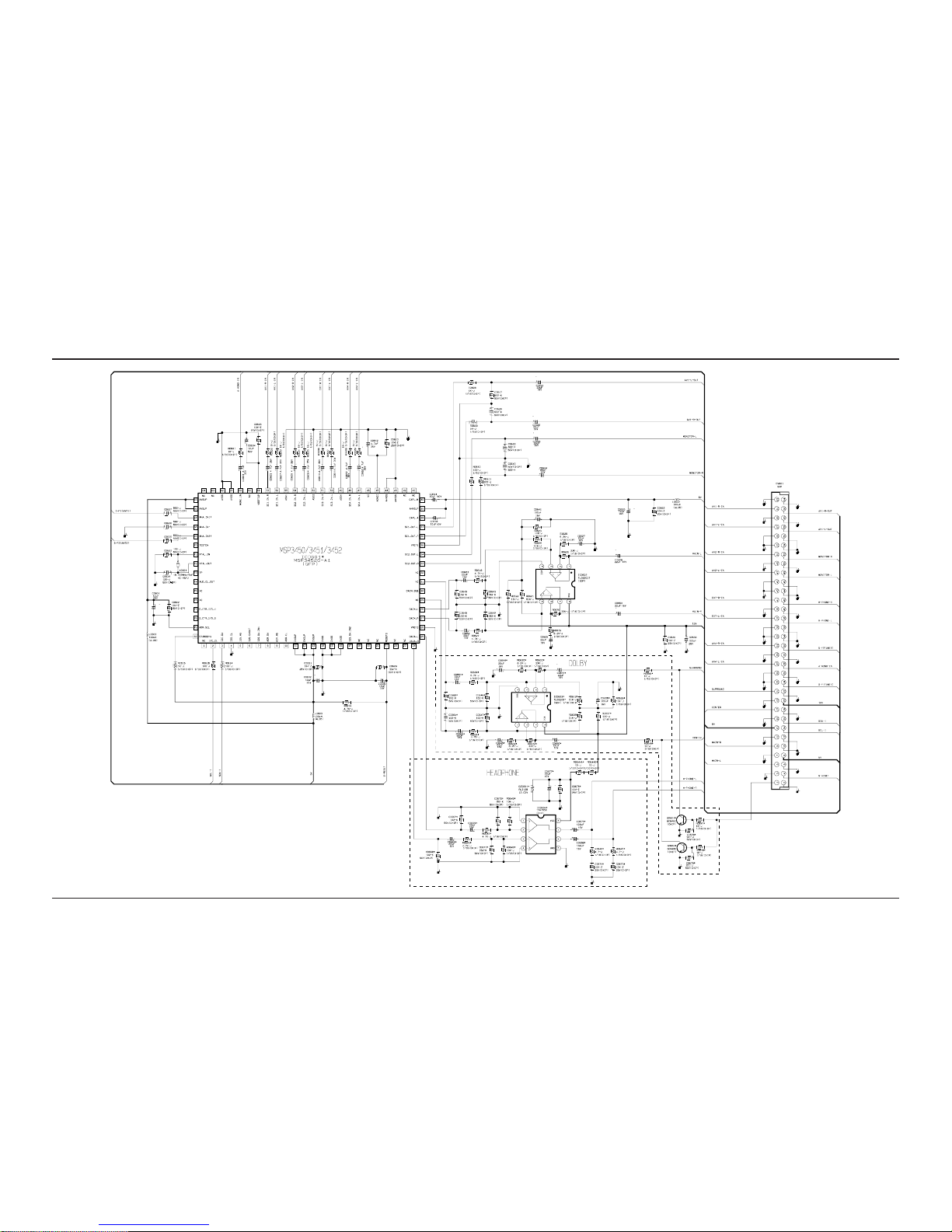
Schematic Diagrams
10-10 Samsung Electronics
10-10 SOUND
 Loading...