

Samsung SP46L5HR1X/XTT, SP46L5HX1X/XS, SP46L5H1X/BWT Service Manual
COLOR TELEVISION RECEIVER
Chassis : L63A(P)_Rev.1
Model : SP46L5HR1X/XTT
SP46L5H1X/BWT
SP46L5HX1X/XSA
COLOR TELEVISION RECEIVER CONTENTS
Alignment and Adjustments
Exploded Views and Parts List
Service Item
PCB Diagram
Schematic Diagrams
1.
2.
3.
4.
5.
ELECTRONICS
© Samsung Electronics Co., Ltd. Dec. 2003
Printed in Korea
AA82-01250A
This Service Manual is a property of Samsung Electronics Co.,Ltd.
Any unauthorized use of Manual can be punished under applicable
International and/or domestic law.
Alignment and Adjustments
Samsung Electronics 1-1
1. Alignment and Operation Checks
1-1 To enter the Factory mode and to select the item
1) Press the factory remote control keys in the following sequence : Display->Fcatory
2) Press the user remote control keys in the following sequence :
(In the standby mode) Display->Menu->Mute->Power
3) Move to target item with Up/Down cursor key or Channel Up/Down key.
4) Select target item with Left/Right cursor key or Volume Up/Down key.
1. ASI500 (Main) 8. DNIe
2. ASI500 (Sub) 9. L3E7050K (Epson)
3. VPC3230 (Main) 10. M62392E
4. VPC3230 (Sub) 11. DDP1010 (DLP)
5. FLI2200 12. Test Pattern
6. AD9888 13. Option Table
7. CXA2151Q 14. Reset
[Factory Main Menu]
1-2 Image position Adjustment
1) Select L3E7050K in Factory Main Menu.
2) Horiziontal Adujustment : Use the sub item H Position (25) of L3E7050K.
The default value is 40.
3) Vertical Adjustment : Use the sub item V Position (26) of L3E7050K.
The default value is 17.
9. L3E7050K (Epson)
25. H position 40
26. V position 17
1) White Balance is individually adjustment per four for each different input modes; Video
(RF/VIDEO/Component SD), Component HD, PC and DVI.
2) Lowlight adjustment :
- Adjust it by changing Bright R/G/B Center value in DNIe item.
- Generally fix Bright G Center value, and change Bright R Center and Bright B center values.
- The Brightness of each color will get higher as the value increases.
- The default value of Video mode is 117, while it is 128 for Component HD, PC and DVI modes.
1-3 White Balance Adjustment
8. DNIe
27. Bright R Center
28. Bright G Center
29. Bright B Center
Alignment and Adjustments
1-2 Samsung Electronics
3) Highlight adjustment
- Adjust it by changing R/G/B Contrast in L3E7050K item.
- Generally, fix G Contrast value, and change R Contrast and B Contrast values.
- The gain of each color will get higher as the value increases.
- Contrast 20 will be changed by step 20, and Contrast 01 will be changed by step 1.
- The default value of Video and Component HD mode is 512, while it is 500 for PC and DVI modes.
9. L3E7050K (Epson)
01 R Contrast 20
02 R Contrast 01
03 G Contrast 20
04 G Contrast 01
05 B Contrast 20
06 B Contrast 01
1-4. Test Patterns
The factory mode has various built-in test patterns.
Test Pattern
01 Cross Bar 14 Dark 4%
02 Cross Hatch 15 Step 64
03 Checker 16 Step 32
04 Character 17 Step 16
05 Box 18 Step 8
06 Single Color 19 Color B ar
07 White 75% 20 F licker_100
08 White 50% 21 F licker_75
09 White 25% 22 F licker_50
10 White 10% 23 F licker_25
11 Dark 1% 24 Pattern Tone 3
12 Dark 1.5% 25 V _Fr equency_60Hz 0
13 Dark 3% 26 OSD Mixed 0
[
‚† Test Pattern Menu]
1) Using method (Example: Step (18) test pattern)
- Move cursor to Step 8(18) test pattern 8 with up/down direction key or channel up/down key
of transmitter.
- Activate the test pattern with left/right direction key or volume up/down key of transmitter.
- Test pattern of white, blue, red, and green will be displayed in turn with press on left/right
direction key or volume up/down key.
- The display will be returned to the test pattern menu with press on up/down direction key or
channel up/down key at the test pattern display status.
- The display will be returned to the main menu of the factory mode with press on menu key at
the status of the test pattern display status.
2) Types of patterns
A) LCD patterns: These patterns are made from LCD driver board, which are ranged from
Single Color (06)to Dart 4%(14) pattern.
Alignment and Adjustments
Samsung Electronics 1-3
- Function of Pattern Tone(24): Only available on LCD patterns
* 1: Test pattern signal is displayed after adjusted with white balance and gamma correction.
* 2: Test pattern signal is displayed after adjusted with gamma correction.
* 3: Test pattern signal is displayed to LCD panel without adjustment. (Mainly used to
measure optical characteristics.)
- Normal display of LCD pattern indicates at least that the status of optical engine including the
LCD board is normal.
B) Scaler Patterns: These patterns are made from scaler IC on digital board which are ranged from
Cross Bar(01) to Box(05) and from Step 64(15) to Flicker_25(23) pattern.
- OSD Mixed: Only available on Scaler Patterns.
* 0: Test pattern will disappear when the display is returned to the menu at test pattern display status.
* 1: Test pattern will be a background picture when the display is returned to menu at test
pattern display status.
- Normal display of scaler patterns means at least the parts after scaler IC are normal.
1-5 M62392E LCD driver control
It Item Default Fuction em Default F uction
01 V middle 1 1
1
1
1
1
85 F ix ed 4 D ->L Trans - Refer below
02 V refence 230 F ix ed 5 LCD All Initial - Don't use
03 NRSL 103 F ix ed 6 OSD Start P os 00 F ix ed
04 NRSH Red 96 Fix ed 7 LCD E E P - Refer below
05 NRSH Green 96 Fix ed 8 DIG EE P - Refer below
06 NRSH Blue 96 Fix ed
07 LCCOM Red 94 Red F lick er control
08 LCCOM Gree 94 Gr een F licker conrol
09 LCCOM Blue 94 Blue Flicker contr o l
10 UpDown 01 Image F lip
11 LeftRight 01 Image F lip
12 Uniformity 00 Fix ed
13 Cremo D ebug 00 F ix ed
M62392E Menu]
[
1) LCD EEP &DIG EEP
- LCD board and digital board can simultaneously backup the data of gamma (uniformity) and
flicker adjustment, because they have the same capacity of EEPROM.
- LCD EEP: It indicates the status of EEPROM in the LCD board.
* Cremo: With the eguipment used during engine assembly at the factory, it indicates that the adjusted
gamma and flicker data is stored.
* Download: It indicates that the gamma and flicker data on the digital board is downloaded and
stored through D->L Trans(14) operation.
At replacement of the LCD board, 14 D->L Trans operation should be carried out.
* Default: It indicates that the default value of Gamma and flicker data is stored.
- DIG EEP: It indicates the status of the EEPROM of the digital board.
* Download: It indicates that the gamma and flicker data on the LCD board is downloaded and
stored through factory reset operation. At replacement of the digital board, the data in EEPROM of
the LCD board should be backed up to EEPROM of the new digital board by factory reset.
* Default: It indicates that the default value of gamma and flicker data is stored.

Alignment and Adjustments
1-4 Samsung Electronics
Digital Board LCD Board
14 D L T rans (LCD EE P : download)
F actory reset (DIG EE P : download)
Factory
Adjustment
(LCD EEP : Cremo)
[‚† EEPROM Status Diagram]
2)LCCOM (LCD COMMON VOLTAGE)
- LCCOM Red: It is used for the LCCOM adjustment of the Red panel.
It adjusts the flicker of the Red panel.
- LCCOM Green: It is used for the LCCOM adjustment of the Green panel.
It adjusts the flicker of the Green panel.
- LCCOM Blue: It is used for the LLCOM adjustment of the Blue panel.
It adjusts the flicker of the Blue panel.
1-6 Flicker agjustment
* Basically, the flicker is agjusted to an optimal status during the assembly of the optical engine. In
case additional adjustment is needed, please refer to the following; (ex. Blue panel)
1) Select Test Pattern item.
1) Set item OSD Mixed(26) to 1.
2) Select item Flicker_50(22) (Signal level 50%) pattern.
3) Selecting Blue color, and check the value of the flicker.
4) Press Menu key.
5) Select item M62392E(10).
6) Adjust flicker by selecting item LCCOM Blue(9).
7) Press again Menu key.
8) Select test pattern item, and return item OSD Mixed(26) to 0
Alignment and Adjustments
Samsung Electronics 1-5
D efa ult (E u r o pe ) Default (Asia) ETC
01 Europe Asia Dependent on Area
02 - - Dependent on Nation
03 Scar t RCA Sc art/RC A
04 ATM Area ATM/Area
05 CW CS
06 On On
07 On On
08 - - Dependent on Area
09 3 3
10 Off Off
11 On On
12 Last Memory Last Memory Last/Wide
13 Normal Normal Normal/Wide/Panorama
14 12Hrs 12Hrs 12Hrs/24Hrs
15 TV TV T V/L ast memory
16 On On
17 01 01
18 01 01
19 05 05 Power on/off Melody volum e
20
0/0
0/0
Fixed
21 0 0 Fixed
22 On On
23 - 24
25 Off Off
26 On On
27 - - OSD language selection
28 - - See 5- 8. 61" Option
Ite m
Language Group
L an g uag e
Jac k T y pe
AT M/Ar ea
CW/CS
LNA
TOP TTX
TTX Group
TTX Contrast
High Deviation
Carrier Mute
Picture Aspect
Scar t WSS
C loc k Dis play
AV Input
Plug & Play
P ix e l Num be r
Pixel T ime
Melo d y Volum e
PAL OSD/D NIe Shift
NT OSD Shift
Auto Po wer
Lamp Time
Lamp Time Clear
Pixel Shift
DN Ie De mo
Ar ab ic/Per sian
61 In c h
or 0/-1 or 0/-1
1-7 Option Tables
Alignment and Adjustments
1-6 Samsung Electronics
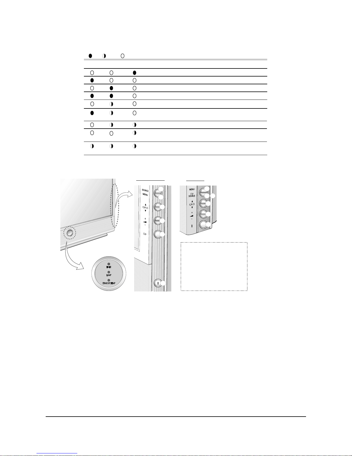
1-8 LED Operation
(
:On,
:Blinking, : off
)
TIMER LAMP STAND BY/TEMP Indication
Standby mode.
A timer pilot light when Timer Auto On or is selected.
Normal operation
Normal operation(When Timer Auto On or off is selected.)
The normal picture comes on after 25 seconds.(when Timer Auto On or
off is seleted.
Air vent cover in the rear of the TV is not properly installed.
Inside temperature of the TV is over normal. Clean the air vent cover in
the rear of the TV. Turn the TV back on after 1hour.
The lamp does not work, please contact an authorized service center for
assistance.
Lamp is warming up. The normal picture comes on after 25 seconds.
1-9 61” Option
a
d
c
b
e
f
b
d
c
a
f
e
(a) Input Source Selection
(b) Menu Display
(c) Channel Selection
(d) Volume Adjustment
(e) Confirm your choice
(Store or Enter)
(f) Power On/Off
SP43L2/50L2HX
SP61L2HX
LED Indicators
* The 61" model has no additional Enter button, and the Source button provides an Enter
function as well. That is, the Source button is for Entering with at status with the OSD menu,
while it is also for the Source Selection at status without OSD menu.
1-10 Lamp Time Clear
* Existing lamp time should be cleared after replacing lamp.
1) Select Option Table.
2) Run item lamp time clear(24) on the 2nd page of option table.
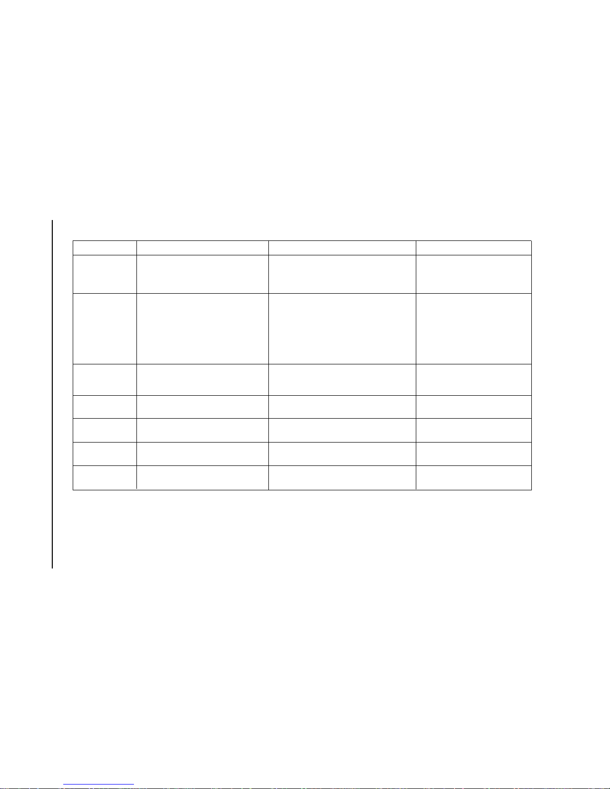
1-11 Display spots
1) Appearance: Some areas, lines, or points with black, cyan, yellow, magenta, etc, that is not white color
are found in the white (10~100%) picture among repose pictures, and in some cases, red, green, blue color
of area is appeared at black picture.
Alignment and Adjustments
Samsung Electronics 1-7
2) Types
Screen dust
Engine dust
Mirror or Screen
contamination
Bad Mirror Shape
Bad Uniformity
Contamination of
transmitting Lens
Bad transmitting Lens
Appearance
Cause
Countermeasure
1 to 3mm diameter of surrounding boundary is
seen clear at white picture, and is more of a
polygon than circle. (It’s the same with the
shape of dust)
It is found well from white 40 to 80% as cyan,
yellow, or magenta color etc, and has the 8 to
20mm circle of shape with unclear boundary.
Water drop shape is displayed on a white
picture, and its surrounding boundary is a little
cloudy.
Various shapes are displayed with a cloudy
surrounding boundary in a white picture.
The white picture is very big and black is the
main color found compared to other colors.
A big light pink spot is found in the white
picture.
A wave shape is found in the white picture.
It is caused by contamination due to fingerprint
on the surface of the transmitting lens, etc.
It is caused by a scratch on the surface of the
transmitting lens.
Replace engine.
Clean transmitting lens.
Dust located in the engine lighting system is
blocking the lighting.
Replace engine.
It is displayed on screen in case mirror or
screen inside is contaminated.
Clean Mirror or Screen.
It is caused by dust stuck to the screen inside the
set, caused by static electricity.
A minute dust on the polarizer or panel part of the
engine sticks to one channel among red, green, blue,
and is displayed with its size 60 times increased. The
diameter of dust stuck to a panel part is displayed a
smaller while it is bigger on polarizer.
Dust stuck to a panel is found red, green, blue color,
etc at the same location of black picture.
Reflection image is displayed on the screen due to
light distorted by a pin hole or bad shape on the
reflection side of the mirror.
Replace mirror.
1.Remove dust by discharging high
pressure of air to the filter of the engine.
2.Remove dust with air pump for lens
cleaning after removing cover-lens.
3.Replace engine.
Remove the dust on the screen.
Alignment and Adjustments
1-8 Samsung Electronics
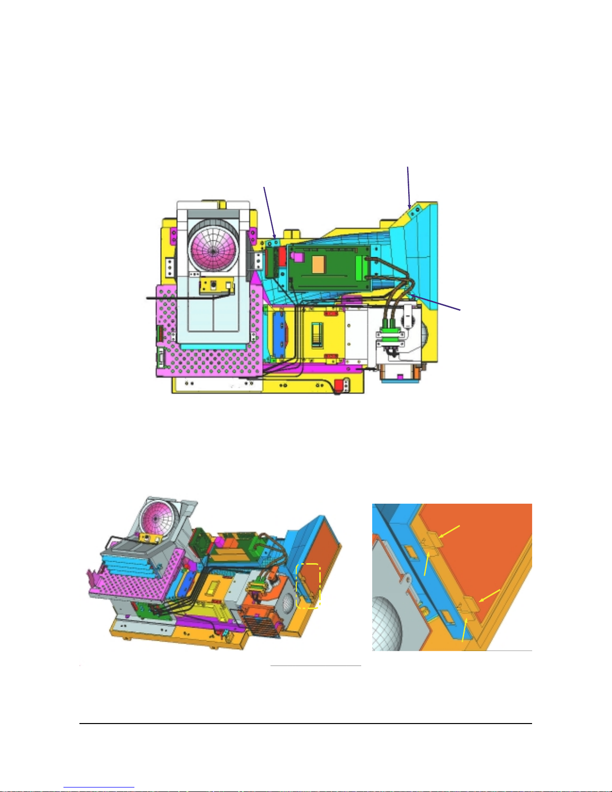
1-12 ASSEMBLY
ASSY COVER P-FAN Separation :
Remove the 3 screws securing the COVER-DUCT, TOP.
ASSY COVER P-FAN Separation :
Pull out the screws while holding and pressing on the HOOK of the HOLDER-FILTER.
1-12-1 ASSY COVER P-FAN
Alignment and Adjustments
Samsung Electronics 1-9
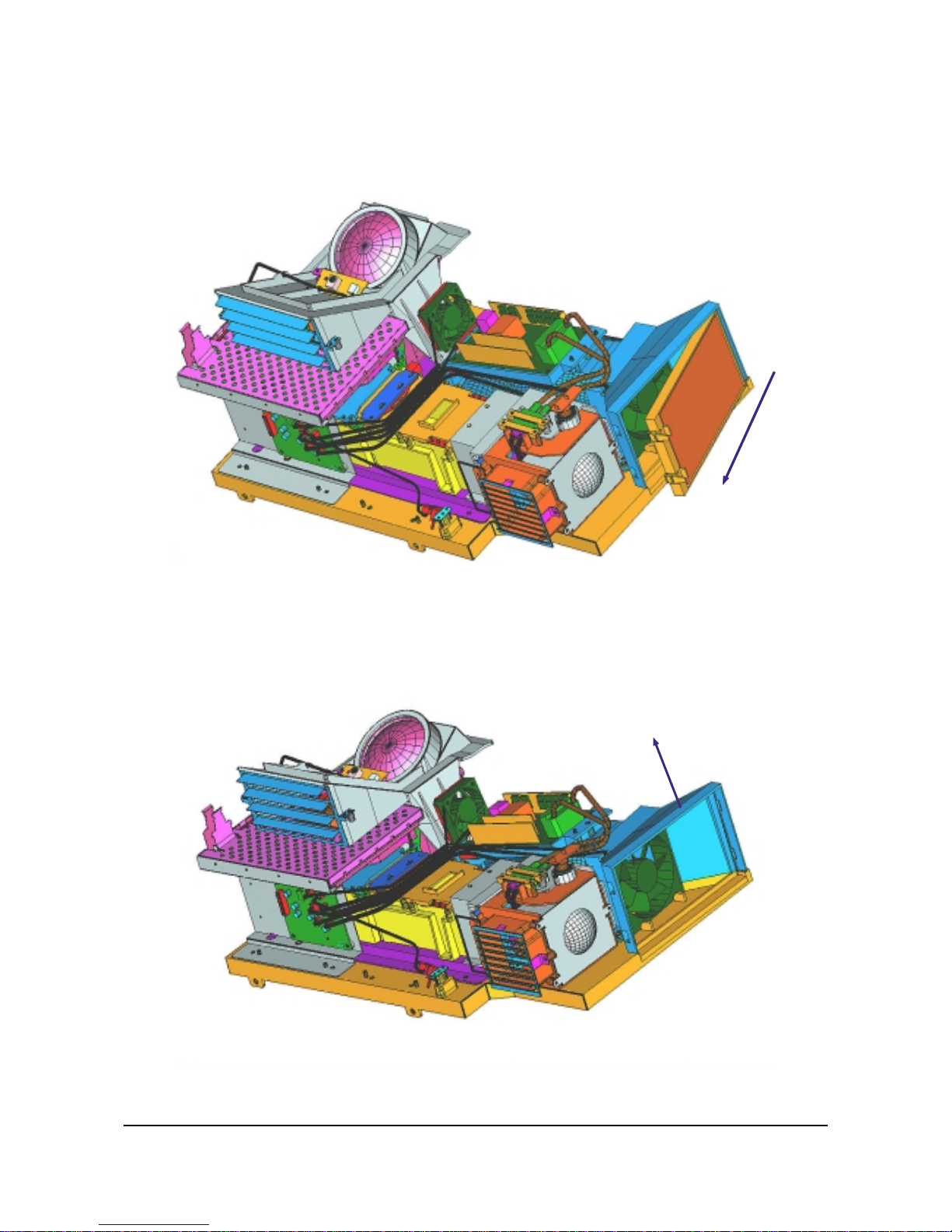
ASSY COVER P-FAN Separation :
Pull out the HANDLE-FILTER in the direction shown in the figure.
ASSY COVER P-FAN Separation :
Lift up the COVER-DUCT TOP with your hand in order to pull out the FAN.
Alignment and Adjustments
1-10 Samsung Electronics
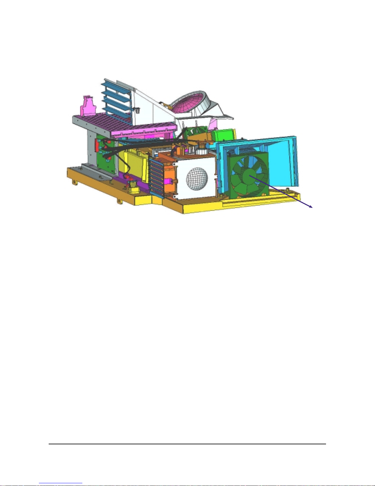
ASSY COVER P-FAN Separation :
Pull out the FAN and let go of the COVER-DUCT TOP .
Alignment and Adjustments
Samsung Electronics 1-11
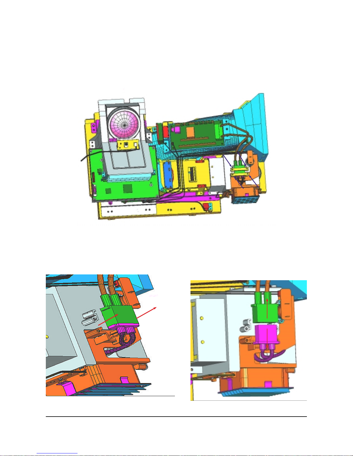
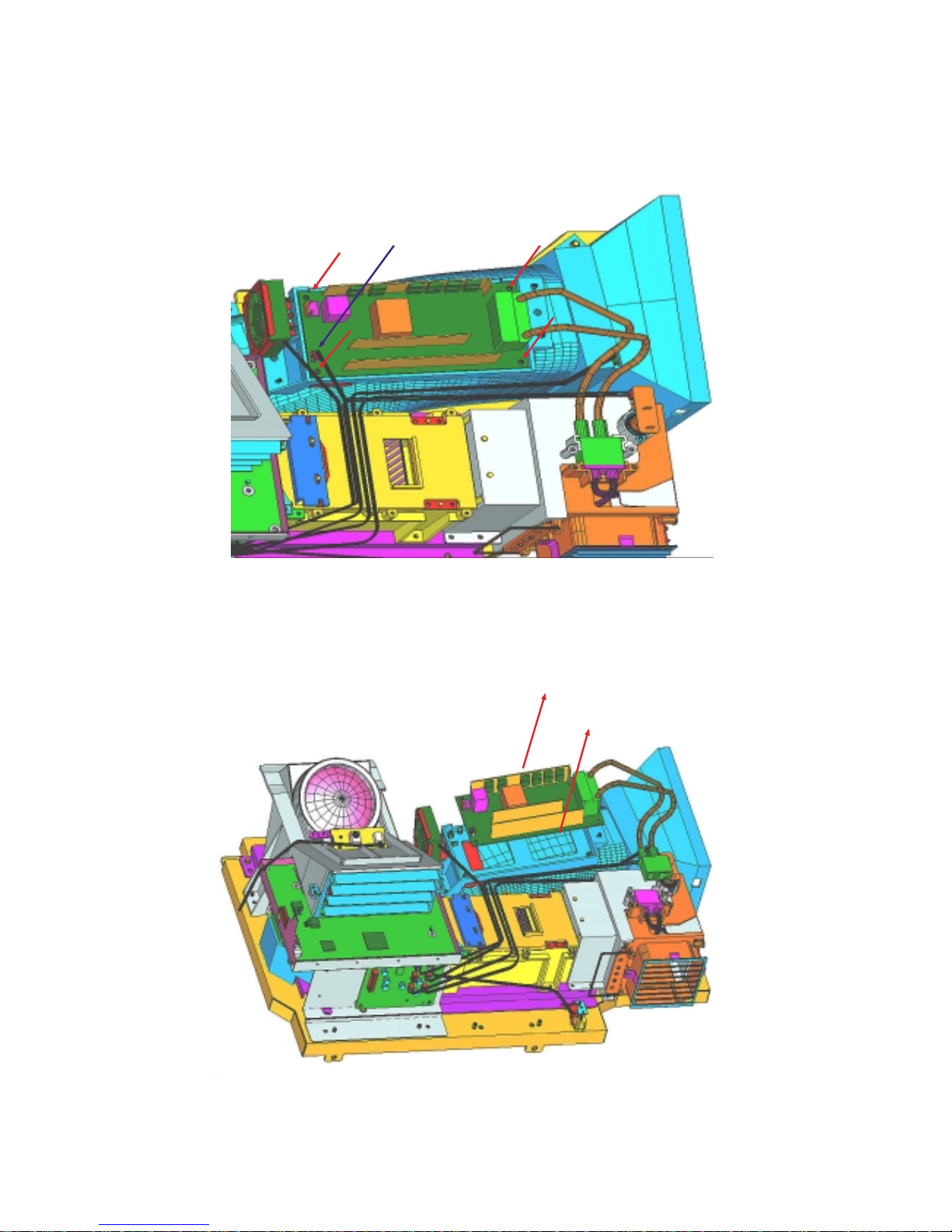
LAMP CONNECTOR Separation :
6003-000335 SCREW-TAPTITE :RH,+2S,M3,L8,ZPC(YEL)SWRCH18A 4EA
Remove the 4 screws in order to pull out the LAMP_BALLAST CONNECTOR
LAMP CONNECTOR Separation :
Pull out the connector connected to the LAMP-BALLAST and the LAMP (Left Figure), and lift it up to
separate the two parts.(Right Figure)
1-12-2 LAMP_BALLAST
LAMP CONNECTOR Separation :
Remove the 4 screws securing the LAMP-BALLAST.
Remove the ON/OFF CABLE inserted in the LAMP-BALLAST.
LAMP CONNECTOR Separation :
Remove the LAMP-BALLAST, and replace it.
Alignment and Adjustments
Samsung Electronics 1-13
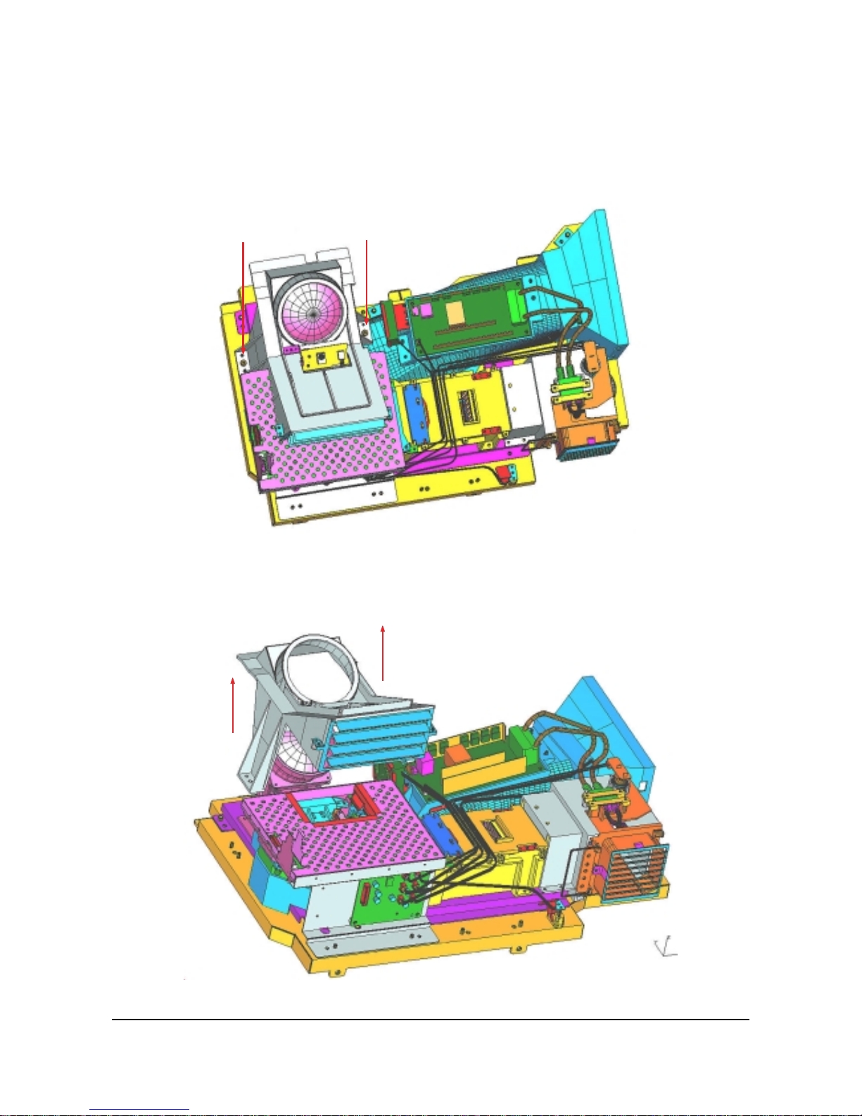
COVER-LENS Separation :
Remove the marked screws.
1-12-3 ASSY PCB S-LCD DRIVER
COVER-LENS Separation :
BP63-00039A COVER-LENS : HIPS VO BLACK
Pull out the COVER-LENS in upward direction as shown in the figure.
Alignment and Adjustments
1-14 Samsung Electronics
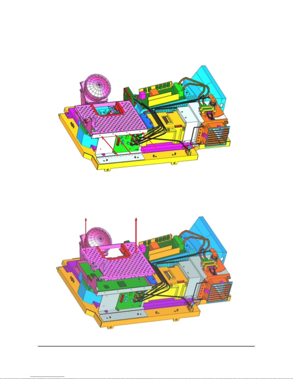
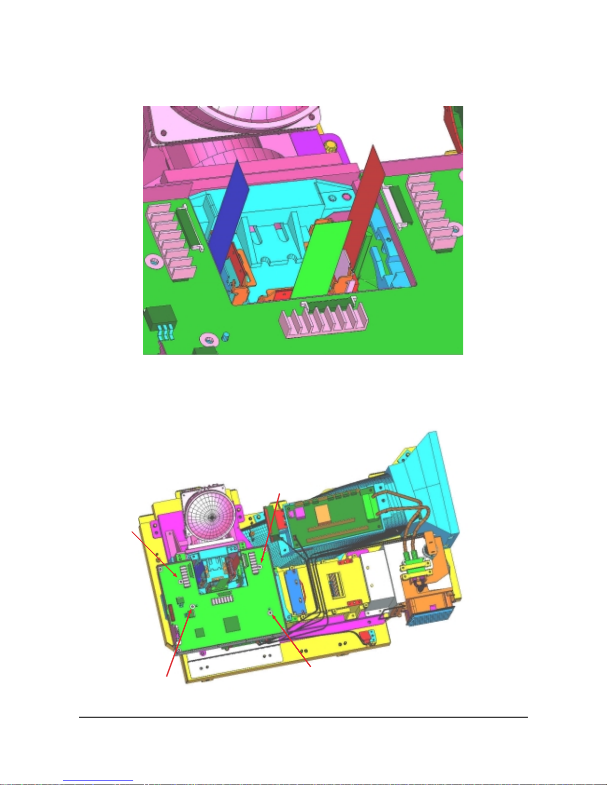
ASSY MISC P-SHIELD-CASE,TOP Separation :
6003-000335 SCREW-TAPTITE :RH,+2S,M3,L8,ZPC(YEL)SWRCH18A
Remove the 4 marked screws.
ASSY MISC P-SHIELD-CASE,TOP Separation :
ABP96-00186A SSY MISC P-SHIELD-CASE,TOP
Hold both sides of the ASSY MISC P-SHIELD-CASE TOP and pull it out in the direction of the arrow to
separate it.
Alignment and Adjustments
Samsung Electronics 1-15
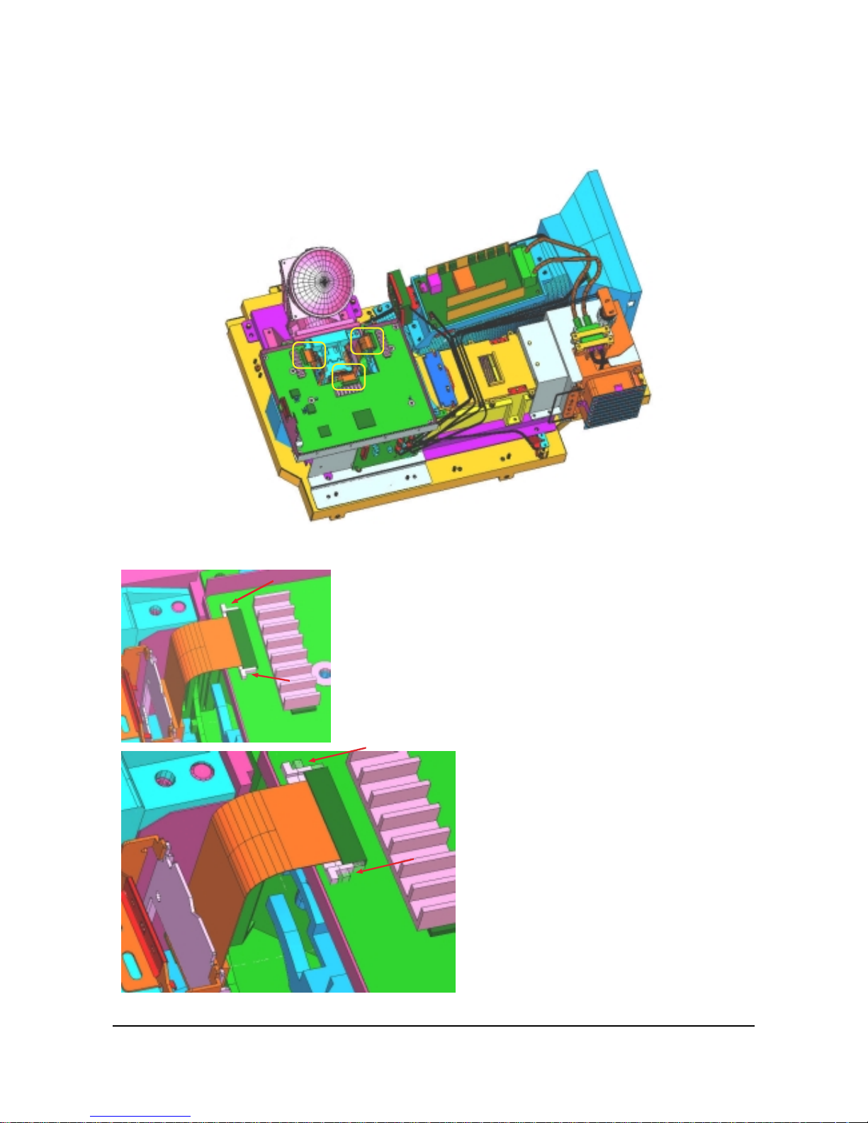
LCD-PANEL Separation :
Separate the 3 marked parts of PANEL R,G,B.
Refer to the figure for details.
LCD PANEL Separation :
Separate each PANEL HOLDER
Refer to the figure for details.
LCD PANEL Separation :
Push both sides of each PANEL HOLDER in
direction of the arrow in the figure to separate it.
Alignment and Adjustments
1-16 Samsung Electronics
LCD PANEL Separation :
A figure showing three separated panels
ASSY PCB S-LCD DRIVER Separation :
6003-000365 SCREW TAPTITE : BH S M3 L8 ZPC(YEL) SWRCH18A 4EA
Remove the 4 marked screws.
 Loading...