

Samsung SP43Q5HL1X Schematic

PROJECTION TV RECEIVER
Chassis : P60B(N)_Omega-2
Model : SP43Q5HL1X/XAX
PROJECTION TV RECEIVER CONTENTS
1.
2.
3.
4.
5.
6.
7.
Product Specification
Alignment & Adjustment
Troubleshooting
Exploded View & Part List
Electrical Part List
PCB Diagram
Schematic Diagram
SERVICE
Manual
This Service Manual is a property of Samsung Electronics Co.,Ltd.
Any unauthorized use of Manual can be punished under applicable
International and/or domestic law.
© Samsung Electronics Co., Ltd. Jul. 2005
Printed in Korea
AA82-02857A
ELECTRONICS
Product Specification
Samsung Electronics
1-1
1. Product Specification
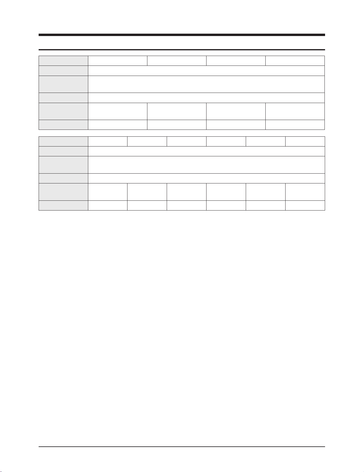
Model HC-R4241W HC-R4741W HC-R4351W HC-R4751W
Voltage AC 120V
Frequency of
Operation
60Hz
Power Consumption 240 watts
Dimension
(W x D x H)
1004 x 500 x 967 mm
39.5 x 19.7 x 38.1 inches
1126 x 621 x 984 mm
44.3 x 24.4 x 38.7 inches
1035 x 510 x 888 mm
40.7 x 20.0 x 34.9 inches
1120 x 555 x 939 mm
44.0 x 21.8x 36.9 inches
Weight 40.4 Kg / 89.1 lbs 49.0 Kg / 108.0 lbs 36.4 Kg / 80.2 lbs 39.5 Kg / 87.0 lbs
Model SP42Q2HL SP47Q2HL SP52Q2HL SP54T8HL SP43Q5HL1X SP47Q5HL1X
Voltage AC 100-240V
Frequency of
Operation
60Hz
Power Consumption 240 watts
Dimension
(W x D x H)
1004 x 500 x 967 mm
39.5 x 19.7 x 38.1 inches
1126 x 621 x 984 mm
44.3 x 24.4 x 38.7 inches
1226 x 598 x 1276 mm
48.3 x 23.5 x 50.2 inches
1525 x 635 x 1162 mm
60.0 x 25.0 x 45.7 inches
1035 x 510 x 888 mm
40.7 x 20.0 x 34.9 inches
1120 x 555 x 939 mm
44.0 x 21.8x 36.9 inches
Weight
40.4 Kg / 89.1 lbs 49.0 Kg / 108.0 lbs 56.3 Kg / 124.1 lbs 76.0 Kg / 167.5 lbs 36.4 Kg / 80.2 lbs 39.5 Kg / 87.0 lbs

1-2
Samsung Electronics
MEMO
2-1-1 How to Enter and Exit Service Mode
1. Turn the Power ON and select "STANDARD" for the Screen Adjustment Mode.
2. Turn the Power OFF and put the set in Stand-By Mode.
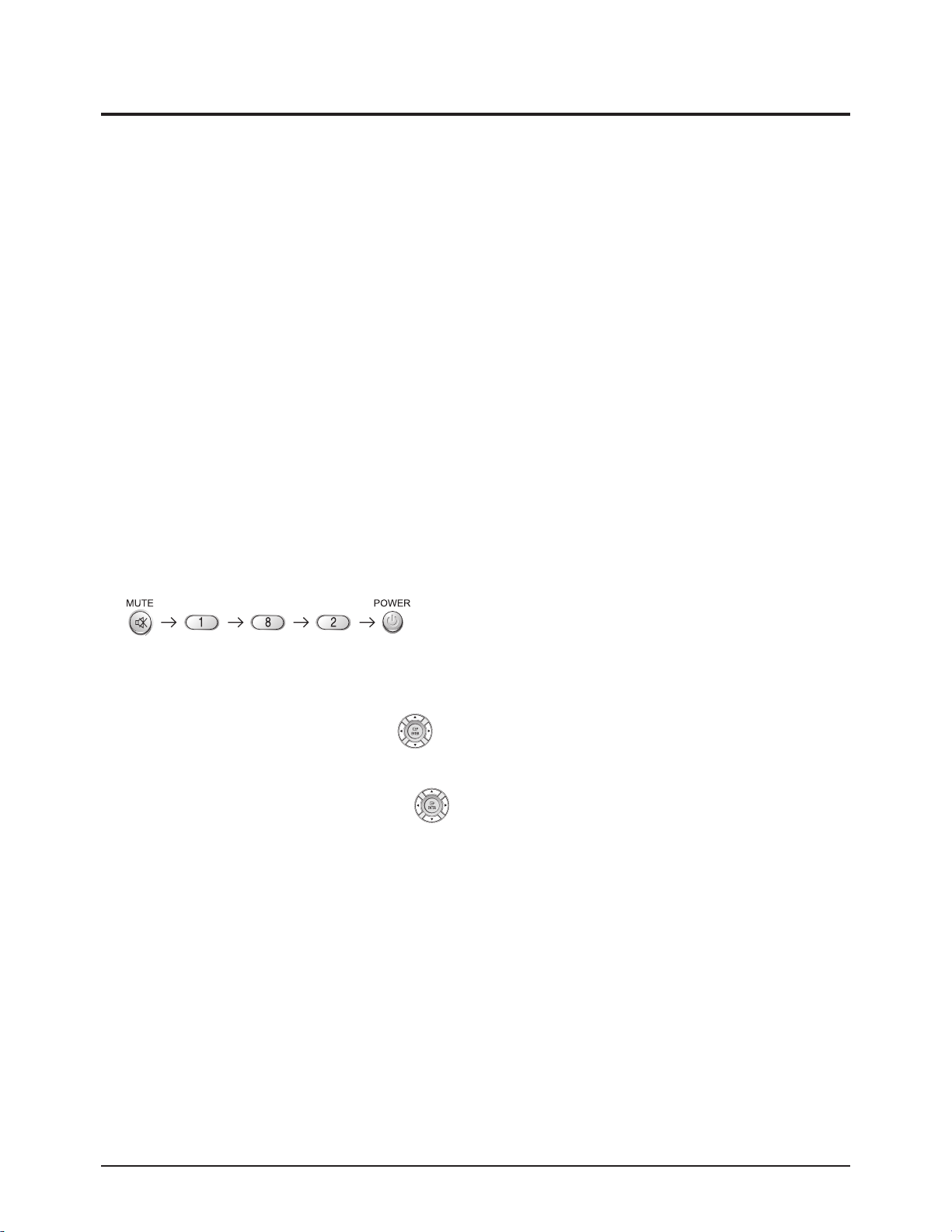
3. Press these buttons sequentially to enter Service Mode : Mute → 1 → 8 → 2 →Power.
※ If you fail to enter Service Mode, try steps 1, 2 and 3 again.
4. After completing the adjustment, select Reset from Service Mode's initial screen to exit Service Mode and turn OFF the Power.
After exiting, the user's custom starting screen will be selected.
5. Any adjustable data changed will be automatically saved.
→ There is no separate "Save" key.
2-1-2 Initial Display in Service Mode
2-1-3 Button Descriptions for Service Mode
2-1-4 Cautions Regarding service Mode
1. Do not adjust the fixed attributes, only the adjustables.
2. For adjustments of RF and 1080i Modes, switch to the respective input source and proceed with the adjustments.
MENU Full Menu Display / Move to Parent Menu
Direction keys ▲ / ▼
Item Selection by Moving the Cursor
Direction keys ◀ / ▶
Data Increase/Decrease for the Selected Item
Alignment & Adjustment
Samsung Electronics 2-1
2. Alignment & Adjustment
2-1 Service Mode
Deflection
480p offset
1080i offset
Convergence & NR
Video Adjust 1
Video Adjust 2
Video Adjust 3
Video Adjust 4
Video Adjust DNIe
Option
CHECKSUM0000
Reset
Alignment & Adjustment
2-2 Samsung Electronics
2-2 Factory Data
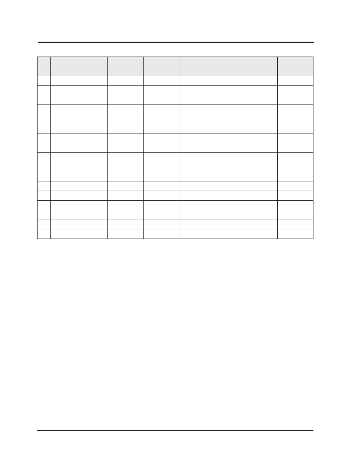
1. Deflection
No Item Initial Data Range
EEP-ROM Copy Data
Remark
RF-Mode
1 V Amp 31 0 ~ 63 28 Adj
2 V Shift 32 0 ~ 63 33 Fix
3 H EW 31 0 ~ 63 31 Adj
4 H Shift 32 0 ~ 63 24 Fix
5 V LInearity 6 0 ~ 63 0 Fix
6 Upper LInearity 7 0 ~ 63 0 Fix
7 Lower LInearity 8 0 ~ 63 7 Fix
8 V SC 3 0 ~ 63 10 Fix
9 H Parabola 10 0 ~ 63 10 Fix
10 Upper Corner 32 0 ~ 63 38 Fix
11 Lower Corner 32 0 ~ 63 31 Fix
12 H Trapezium 32 0 ~ 63 31 Fix
13 Bow 32 0 ~ 63 31 Fix
14 Angle 32 0 ~ 63 31 Fix
15 V Position 32 0 ~ 63 28 Fix
16 CXA Left Blk 32 0 ~ 63 45 Fix
17 CXA Right Blk 32 0 ~ 63 25 Fix

Alignment & Adjustment
Samsung Electronics 2-3
2. 480p offset
No Item Initial Data Range 480p-Mode Remark
1 V Amp 0 -63 ~ 63 0 Adj
2 V Shift 0 -63 ~ 63 0 Adj
3 H EW 0 -63 ~ 63 0 Adj
4 H Shift 0 -63 ~ 63 0 Adj
5 V LInearity 0 -15 ~ 15 0 Fix
6 Upper LInearity 0 -15 ~ 15 0 Fix
7 Lower LInearity 0 -15 ~ 15 0 Fix
8 V SC 0 -15 ~ 15 0 Fix
9 H Parabola 0 -63 ~ 63 0 Fix
10 Upper Corner 0 -63 ~ 63 0 Fix
11 Lower Corner 0 -63 ~ 63 0 Fix
12 H Trapezium 0 -63 ~ 63 0 Fix
13 Bow 0 -63 ~ 63 0 Fix
14 Angle 0 -63 ~ 63 0 Fix
15 V Position 0 -63 ~ 63 0 Fix
16 CXA Left Blk 45 -63 ~ 63 45 Fix
17 CXA Right Blk 25 -63 ~ 63 25 Fix
3. 1080i Offset
No Item Initial Data Range 1080i-Mode Remark
1 V Amp 0 -63 ~ 63 0 Adj
2 V Shift 0 -63 ~ 63 0 Adj
3 H EW 0 -63 ~ 63 0 Adj
4 H Shift 0 -63 ~ 63 0 Adj
5 V LInearity 0 -15 ~ 15 0 Fix
6 Upper LInearity 0 -15 ~ 15 0 Fix
7 Lower LInearity 0 -15 ~ 15 0 Fix
8 V SC 0 -15 ~ 15 0 Fix
9 H Parabola 0 -63 ~ 63 0 Fix
10 Upper Corner 0 -63 ~ 63 0 Fix
11 Lower Corner 0 -63 ~ 63 0 Fix
12 H Trapezium 0 -63 ~ 63 0 Fix
13 Bow 0 -63 ~ 63 0 Fix
14 Angle 0 -63 ~ 63 0 Fix
15 V Position 0 -63 ~ 63 -1 Fix
16 CXA Left Blk 50 -63 ~ 63 50 Fix
17 CXA Right Blk 25 -63 ~ 63 25 Fix

Alignment & Adjustment
2-4 Samsung Electronics
4. Convergence & NR
No Item Initial Data Range RF Remark
1 Offset Enable 0 0 ~ 1 0 Fix
2 V AMp 15 -63 ~ 63 5 Fix
3 V Shift 0 -63 ~ 63 0 Fix
4 H EW 15 -63 ~ 63 0 Fix
5 V Amp 1080i 15 -63 ~ 63 5 Fix
6 V Shift 1080i 0 -63 ~ 63 0 Fix
7 H EW 1080i 15 -63 ~ 63 5 Fix
8 NR High Ref 40 0 ~ 127 40 Fix
9 NR Low Ref 3 0 ~ 127 3 Fix
10 NR Hight Value 17 -128 ~ 127 17 Fix
11 NR Low Value 51 -128 ~ 127 51 Fix
12 NR Hight Ref (s) 20 0 ~ 127 17 Fix
13 NR Low Ref (s) 0 0 ~ 127 0 Fix
14 NR Hight Value (s) 17 -128 ~ 127 17 Fix
15 NR Low Value (s) 50 -128 ~ 127 50 Fix
16 NR Read M/S Read Data

Alignment & Adjustment
Samsung Electronics 2-5
5. Video Adjust 1
No
Video Adjust 1
(RF/1080i is Separated)
Initial Data Range
ALL-Mode
(Except 1080i)
1080i Remark
1 R Cutoff 25 0 ~ 63 25 25 Adj
2 G Cutoff 25 0 ~ 63 25 25 Fix
3 B Cutoff 25 0 ~ 63 25 25 Adj
4 COLOR On/Off 1 0 ~ 1 1 1 Fix
5 CR Offset 32 0 ~ 63 32 32 Adj
6 CB Offset 32 0 ~ 63 32 32 Adj
7 R Drive 25 0 ~ 63 35 35 Adj
8 G Drive 25 0 ~ 63 35 35 Fix
9 B Drive 25 0 ~ 63 35 35 Adj
10 Sub Bright 15 0 ~ 63 15 15 Adj
11 Sub Contrast 7 0 ~ 15 7 7 Adj
12 Sub Color 21 0 ~ 23 23 16 Fix
13 Sub Tint 8 0~ 13 8 8 Fix
14 CTI Level 1 0 ~ 3 1 1 Fix
15 COL AXIS 3 0 ~ 3 1 1 Fix
16 LTI Level 1 0 ~ 3 1 2 Fix
17 9405 U-OUT 207 0 ~ 255 207 207 Fix
18 9405 Y-OUT 111 0 ~ 255 111 111 Fix
19 9405 V-OUT 211 0 ~ 255 211 211 Fix

Alignment & Adjustment
2-6 Samsung Electronics
6. Video Adjust 2
No
Video Adjust 2
(RF/1080i is Separated)
Initial Data Range
ALL-Mode
(Except 1080i)
1080i Remark
1 ABL mode 3 0 ~ 3 3 3 Fix
2 Gamma 2 0 ~ 3 1 1 Fix
3 DPIC Level (DNP) 3 0 ~ 3 3 2 Fix
4 DC Tran 2 0 ~ 3 3 2 Fix
5 ABL TH 15 0 ~ 15 15 (ALL-mode) 15 Fix
6 VM Level 2 0 ~ 3 3 (ALL-mode) 3 Fix
7 VM Coring 0 0 ~ 3 0 0 Fix
8 VM fo 0 0 ~ 3 0 1 Fix
9 VM Limit 0 0 ~ 3 0 0 Fix
10 VM Delay 0 0 ~ 3 3 (Except 480p) 1 (480p) Fix
11 SHP CD 1 0 ~ 3 1 (ALL-mode) 1 Fix
12 SHP fo 0 0 ~ 1 0 1 Fix
13 SHP f1 & P/O 11 0 ~ 15 13 (ALL-mode) 13 Fix
14 AKB Time 13 0 ~ 31 16 16 Fix
15 YC Delay 30 0 ~ 31 31 31 Fix
16 PIP YC Delay 30 0 ~ 31 30 30 Fix
17 BandPass 9407 2 0 ~ 7 1 1 Fix
18 HighPass 9407 3 0 ~ 7 2 2 Fix

Alignment & Adjustment
Samsung Electronics 2-7
7. Video Adjust 3
No
Video Adjust 3
(All Mode Equality)
Initial Data Range ALL-Mode Remark
1 Pilot Low 10 16 ~ 127 10 Fix
2 Pilot High 16 16 ~ 127 16 Fix
3 H Comp 0 0 ~ 15 1 Fix
4 V Comp 0 0 ~ 15 8 Fix
5 Pin Comp 0 0 ~ 7 0 Fix
6 AFC Comp 0 0 ~ 7 1 Fix
7 Sync Phase 0 0 ~ 1 0 Fix
8 NR Off Value 5 0 ~ 9 0 Fix
9 VSV 2 0 ~ 15 2 Fix
10 Melody Volume 4 0 ~ 20 4 Fix
11 Video Mute Time 500ms 0 ~ 1sec 500ms Fix
12 S-ABL 0 0 ~ 3 0 Fix
13 P_ABL 0 0 ~ 2 0 Fix
14 PLIMT_LEV 0 0 ~ 2 0 Fix
15 AKB 0 0 ~ 1 0 Fix
16 CLP Gate 1 0 ~ 1 1 Fix
17 Color Kil 198 0 ~ 255 198 Fix
18 Real Time(Hour) 72 0 ~ 255 72 Fix
Alignment & Adjustment
2-8 Samsung Electronics
8. Video Adjust 4
No
Video Adjust 4
(Only Indicated Modes)
Initial Data Range Only Indicated Mode Remark1 Remark2
1 System RF 1 0 ~ 3 1 RF Fix
2 System_VSD_480p 1 0 ~ 3 1 VSD=AV/SV/DVD Fix
3 System_1080i 1 0 ~ 3 1 1080i Fix
4 Shp_Fo_VSD_480p 1 0 ~ 3 1 480p Fix
5 HPF_VSD 5 0 ~ 1 3 VSD=AV/SV/DVD Fix
6 BPF_VSD 1 0 ~ 7 1 VSD=AV/SV/DVD Fix
7 Chrm_bdwth_RF 28 0 ~ 7 28 RF Fix
8 Chrm_bdwth_Video 28 0 ~ 63 28 Video Fix
9 Chrm_bdwth_Svideo 30 0 ~ 63 30 S-Video Fix
10 Chrm_bdwth_DVD 28 0 ~ 63 28 DVD Fix
11 IF_Comp_RF 2 0 ~ 63 2 RF Fix
12 IF_Comp_Video 4 0 ~ 7 4 Video Fix
13 IF_Comp_Svideo 5 0 ~ 7 5 S-Video Fix
14 IF_Comp_DVD 4 0 ~ 7 4 DVD Fix
15 VM_Delay_480p 1 0 ~ 3 1 480p Fix
16 1E Data1 9405 15 0 ~ 15 15 All-Mode Fix
17 1E Data2 9405 15 0 ~ 15 15 All-Mode Fix
18 1E Data3 9405 14 0 ~ 15 14 All-Mode Fix
Alignment & Adjustment
Samsung Electronics 2-9
9. Video Adjust DNIe
No Item Initial Data Range RF
AV/SV/
480i/480p
1080i Remark
1 9883 Cr Offset 0 0 ~ 127 0 0 0 Fix
2 9883 Y Offset 0 0 ~ 127 0 0 0 Fix
3 9883 Cb Offset 0 0 ~ 127 0 0 0 Fix
4 NR Scale Max 0 0 ~ 255 0 0 0 Fix
5 NR Scale Min 0 0 ~ 255 0 0 0 Fix
6 NR Sel 0 0 ~ 3 0 0 0 Fix
7 CE Cutoff 0 0 ~ 255 0 0 0 Fix
8 CE Upper 0 0 ~ 255 0 0 0 Fix
9 CE Gain 0 0 ~ 255 0 0 0 Fix
10 CE HPF Gain 0 0 ~ 255 0 0 0 Fix
11 DCE Gain 0 0 ~ 255 0 0 0 Fix
12 CTI Gain 0 0 ~ 15 0 0 0 Fix
13 DEP TH Cor 0 0 ~ 63 0 0 0 Fix
14 DEP OV Gain H 0 0 ~ 255 0 0 0 Fix
15 DEP R INT 0 0 ~ 127 0 0 0 Fix
16 CTE Gain 0 0 ~ 255 0 0 0 Fix
Alignment & Adjustment
2-10 Samsung Electronics
10. Option
MICOM NAME : T-OM2NUS-1XXX
No
Option
(61h 50h)
Initial Data Range
America
42",43",47",52"
South Central
America
42",43",47",52"
Canada
42",43",47",52"
1 CRT 4:3
Wide ↔ 4;3
Wide Wide Wide
2 PIP On
On ↔ Off
Off Off Off
3 3D-Comb filter Off
On ↔ Off
Off Off Off
4 BBE Effect On
On ↔ Off
On On On
5 Auto Power On On
On ↔ Off
On On On
6 Auto Power On On
CT(EN+SP+FR),
CT-A(E+SP+F)
CT(EN+SP+FR) CT(EN+SP+FR) CT(EN+SP+FR)
7 Virtual Dolby Off
On ↔ Off
Off Off Off
8 ACS On
On ↔ Off
On Off Off
9 V Chip(CT,CTA) On
On ↔ Off
On Off Off
10 V Chip Area USA USA USA USA USA+CANADA
11 Sub Woofer Off
On ↔ Off
Off Off Off
12 No Sync Mute On
On ↔ Off
On On On
13 AGC Off
On ↔ Off
Off Off Off
14 Turbo Effect Off
On ↔ Off
Off Off Off
15 Burst Screen Off
On ↔ Off
Off Off Off
16 LNA Off
On ↔ Off
On On On
17 Pixelshift 1 1 ~ 5, Off 1 1 1
18 PS Time(MIN) 60 1,30,60,Off 60 60 60
Alignment & Adjustment
Samsung Electronics 2-11
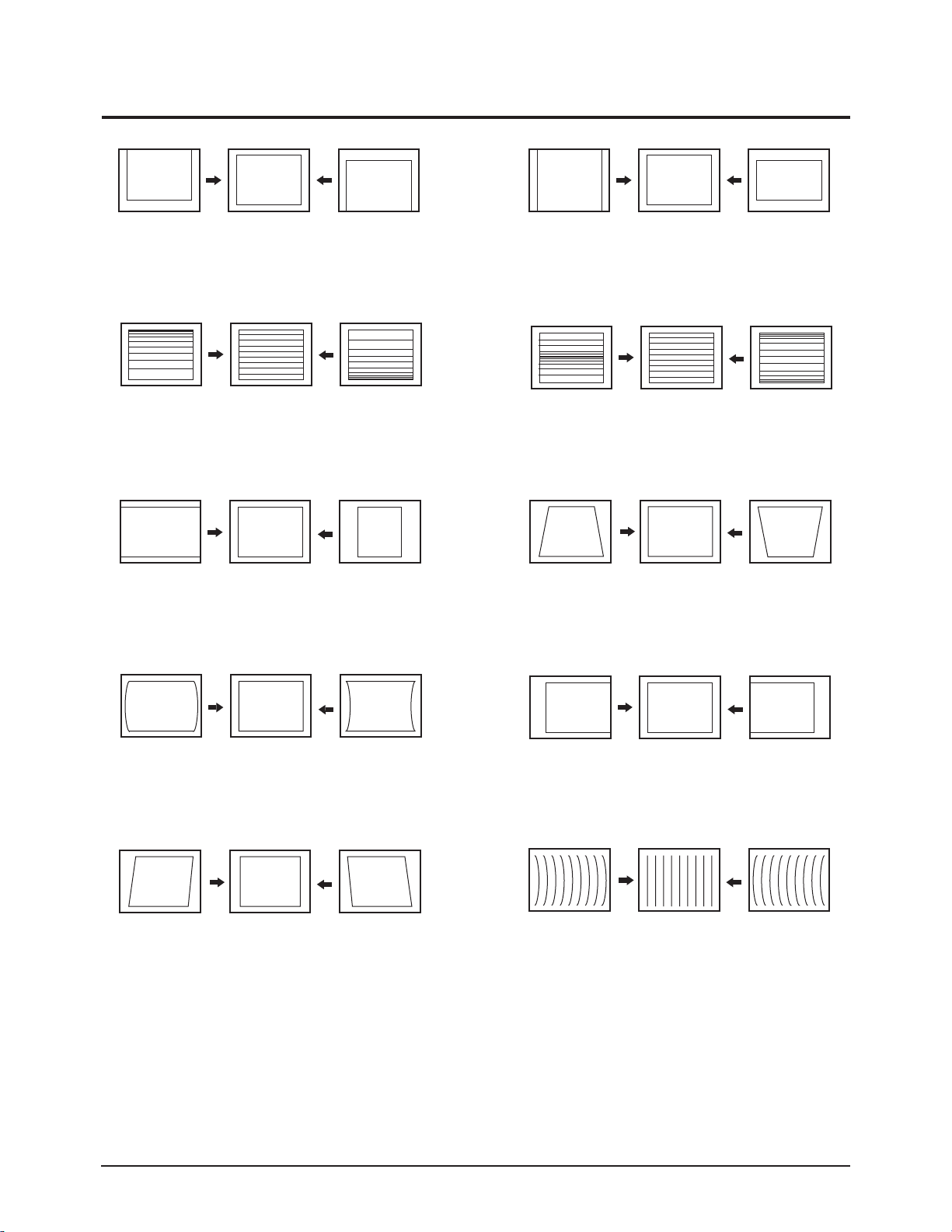
2-3 Screen Change (When adjusting I2C Bus Geometric items)
6
1 V SHIFT
2
V LINEARITY
3
H SIZE
V SIZE
7
V - S - CORRECTION
8
PIN PHASE
4
5
PIN AMP
V ANGLE
9
10
H SHIFT
V BOW
Alignment & Adjustment
2-12 Samsung Electronics
2-4 Other Adjustments
2-4-1 Screen Adjustment
1. Warm up the TV for at least 30 minutes.
2. Select the "STANDARD" Video Mode.
3. Turn to the Video Mode (No Signal) using a remote-control.
4. Connect an oscilloscope to RK,GK,BK.
5. Adjust the VR Screen (in the Focus Pack) to have 20VP-P for the RK, GK and BK pulse.
(Turn the R, G and B VR screen fully counterclockwise at each flyback line.)
※ Voltage adjustment connt be done using a normal multi-tester. For adjustment, use an oscilloscope.
The voltage shown by the tester is false data because the AC peak to peak voltage is adjusted under DC
conditions.
2-4-2 White Balance Adjustment
1. Select the "STANDARD" Video Mode.
2. Input 100% white pattern.
3. In the stand-by mode, press the remote-control keys in the following sequence:
4. Warm up the TV for at least 30 minutes.
5. Input a 10-step signal.
6. R-cut off, B-cut off, and G-cut off by pressing the keys.
7. Adjust the low light with viewing the dark side of the screen.
8. Select R-drive, G-drive, and B-drive by pressing the keys.
9. Adjust the high light with viewing the light side of the screen.
10. If necessary, redo screen adjustments and 6~9.
11. Press the Add key to exit.

Alignment & Adjustment
Samsung Electronics 2-13
2-4-3 Sub-Brightness Adjustment
1. Input a sub-brightness adjustment signal. (TOSHIBA PATTERN)
2. In the stand-by mode, press the remote-control keys in the following sequence :
3. Select SBT by pressing the keys.
4. Adjust so that the 63 step on the right side of the screen is not seen (Use the keys).
5. Press the Menu key to exit.
2-4-4 Static Focus Adjustment
Precaution
1. Select the "STANDARD" video mode.
2. Input a crosshatch pattern.
3. Cover the lenses that are not being adjusted.
4. Connect a convergence jig and read data.
5. Adjust the lens for best focus. (See Fig, 2-1)
Static Focus (continued)
Vary the focus pack VR (Red, Blue) on the front cabinet. Adjust the TV for best possible focus around the center of the
crosshatch pattern, without losing overall screen balance. Figure Crosshatch Pattern Examine these points together.
2-4-5 Lens Focus Adjustment
1. Preparation
① Set the Screen to "STANDARD". (Contrast : 100 / Brightness : 50)
② Set the pattern to Crosshatch.
③ Adjust the electric focus before beginning.
④ Adjust the DY tilt (TILT) before beginning.
2. How to Adjust (Green Lens Adjustment)
① Loosen the lens screw for easier adjustment.
② Press Mute, 1, 8 and 3, sequentially to enter Convergence Mode.
③ Display only the Green pattern by using the +100, 0, and Previous Channel Keys in order to turn the R, G, and B patterns
On/Off respectively.
④ Turn the Green Lens clockwise/Counterclockwise to adjust for optimum status.
(Repeat if unsuccessful, varying the VR of the front Focus Pack.)
⑤ Perform steps 1~3 for the R and B Lenses.
3. Note
Green determines picture quality; pay close attention for exact adjustment.
Examine these points together
Fig. 2-1 Crosshatch Pattern.
Red Chromatic Number
Blue Chromatic Number
P
L1
L2
<_
L1, L2 P
Fig. 2-2 Color Aberration

Alignment & Adjustment
2-14 Samsung Electronics
2-5 Beam Alignment Adjustments
1. Select the "STANDARD" Video Mode.
2. Warm up the set at least for 10 minutes.
3. Enter the Convergence mode by pressing the remote control buttons in the following sequence.
4. Set the Beam Alignment Adjustment CY to Zero magnetic field area.
5. Press the 7- digit button for a while, on the remote control, and a vibrating dot-pattern appears.
6. Adjust the Focus-pack VR for defocusing.
7. Mute the other patterns (R/B) other than G-PATTERN. (Use "+100" / "PRE-CH" Key on the remote control.)
8. Adjust the 2, 4 polarities of VM-COIL as shown in figure below.
9. Adjust the G-Focus until any light around the core disappears.
10. Adjust G-Focus so that the surrounding flash can disappear from the spot.
11. After G-Focus adjustments are complete, adjust R-Focus as above procedures.
12. The B-CRT adjustments can be omitted because the variance of beam focus is small. (Only Vm-coil is mounted.)
13. Adjust the Focus-pack VR for fine focusing.
14. Press the 7- digit button for a while, on the remote control, and the mode changes to the Convergence Adjustment mode.
15. Press the "S.MODE" Key on the remote control to return to normal viewing.
G-FOCUS
CORE
CORE
G-FOCUS
c
MUTE
(Creation of CPM Zero Magnet) (Creation of the 2-pole/4-pole zero magnets)
G-FOCUS
(Varying G-Focus Pack)
G-FOCUS
(When VM 2-Pole Adjustment is completed) (Adjust until the light around the core becomes a
CORE
Varying the 2-pole of
(Positioning the Core in the Center)
CORE
Varying the 4-pole of VM

Alignment & Adjustment
Samsung Electronics 2-15
2-6 Convergence-Jig
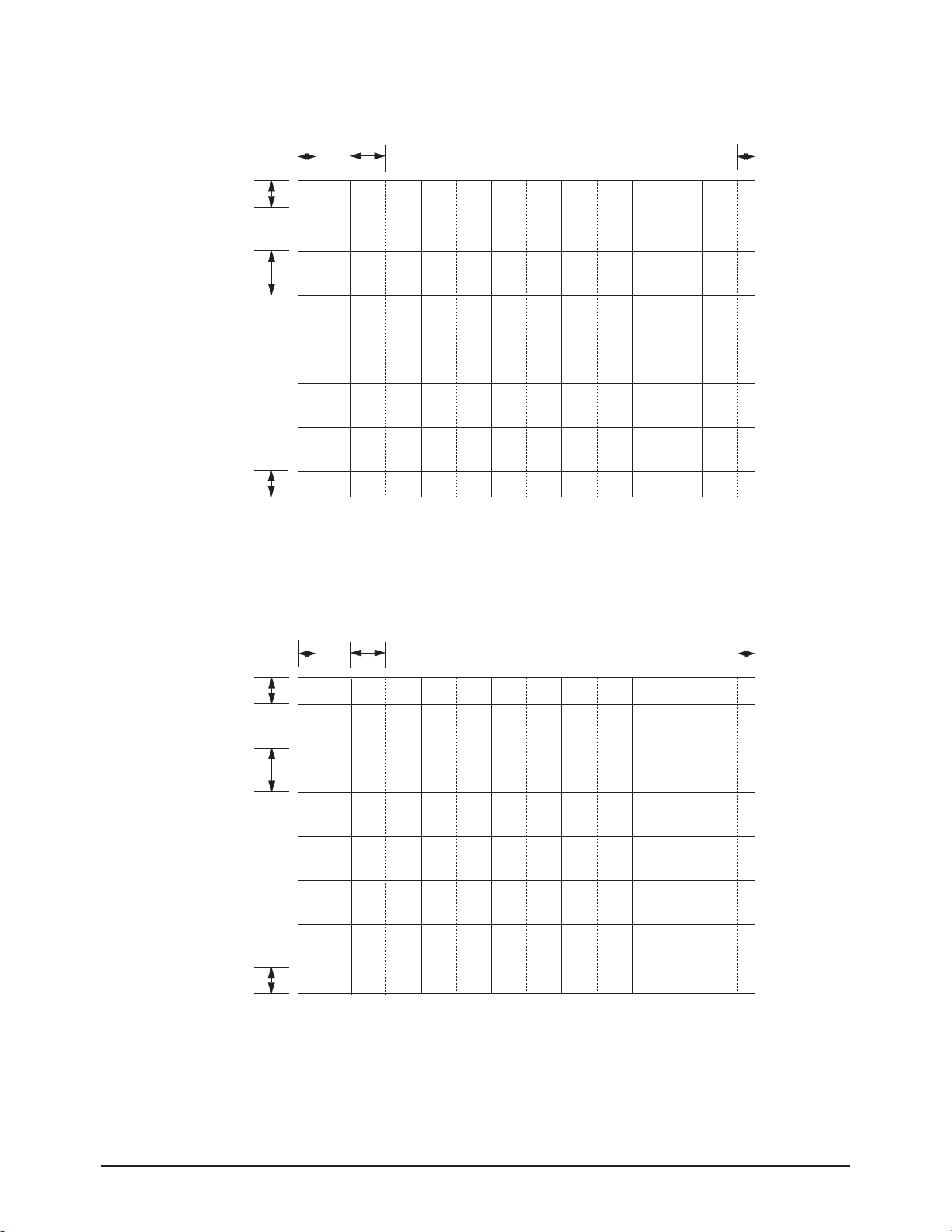
2-6-1 4241W RF Mode
2-6-2 4241W DTV Mode
Screen Size : X 925, Y 523 (X: 378 =9*2 + 30*12 , Y:440=28* 2+64* 6)
22.02mm 73.41mm
33.28mm
76.07mm
33.28mm
22.02mm
42.87mm
72.88mm
42.87mm
Screen Size : X 925, Y 523 (X: 396 =12*2 + 31* 12, Y : 488= 40* 2+68* 6)
28.03mm 72.41mm
28.03mm
Alignment & Adjustment
2-16 Samsung Electronics
2-6-3 4351W RF Mode
2-6-4 4351W DTV Mode
34.84mm
77.89mm
34.84mm
23.89mm 75.44mm
23.89mm
31.59mm 74.19mm
35.50mm
77.67mm
35.50mm
31.59mm

Alignment & Adjustment
Samsung Electronics 2-17
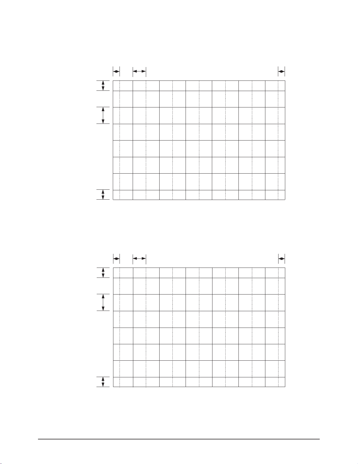
2-6-5 4741W RF Mode
2-6-6 4741W DTV Mode
Screen Size : X 1045, Y 588 (X: 378 =9*2 + 30*12 , Y:440=28* 2+64* 6)
24.88mm 82.94mm
37.42mm
85.53mm
37.42mm
24.88mm
48.20mm
81.93mm
48.20mm
Screen Size : X 1045, Y 588 (X: 396 =12*2 + 31* 12, Y : 488= 40* 2+68* 6)
31.67mm 81.81mm
37.67mm
Alignment & Adjustment
2-18 Samsung Electronics
2-6-7 5241W RF Mode
2-6-8 5241W DTV Mode
Screen Size : X 1153, Y 649 (X: 378 =9*2 + 30*12 , Y:440=28* 2+64* 6)
27.45mm 91.51mm
41.3mm
94.4mm
41.3mm
27.45mm
53.20mm
90.43mm
53.20mm
Screen Size : X 1153, Y 649 (X: 396 =12*2 + 31* 12, Y : 488= 40* 2+68* 6)
34.94mm 90.26mm
34.94mm
Alignment & Adjustment
Samsung Electronics 2-19
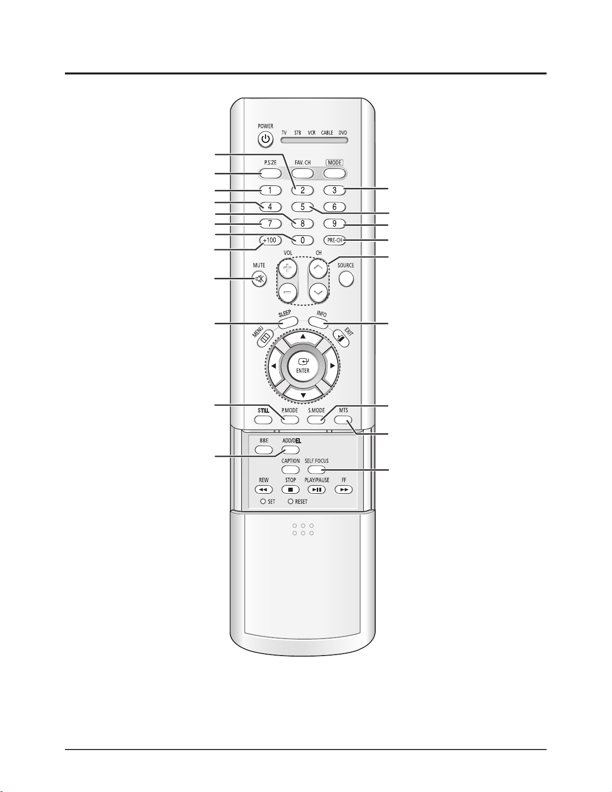
2-7 Remote Control Key Functions in Convergence Mode
Recalls the previous data
before convergence adjustment
(Initializes)
RF to DTV Data Copy (1second push)
Sets Convergence Data to 0
Normal/Line shif
Adjustment Pattern Select Button (Green)
Adjustment Pattern Select Button (Red)
Green Convergence Pattern ON/OFF
Red Convergence Pattern ON/OFF
*Moves the Cursor
(Backwards: Right or Down)
Recovers previous data settings during
Convergence Adjustment or recalls the
last memorized data.
Data Initialize key for each screen size
Adjustment Pattern Select Button (Blue)
Blue Convergence Pattern ON/OFF
Convergence Adjust Button (Left/Right)
Moves the Convergence
Pattern to the right
*Moves the Cursor
(Backwards: Left or Up)
Save data after completing
Convergence Adjustment
Toggles between the Convergence
Adjustment screen and the RF screen
Exit the Convergence Mode and switch to
RF mode
Moves the Convergence Pattern to the left
Automatic Convergence Adjustment
after completing Convergence Adjustments
(Automatic Color Adjustment to
compensate for the earth s magnetic field.)

Alignment & Adjustment
2-20 Samsung Electronics
2-7-1 KEY Function
1. "7" Key : R-Select Key
Press to select RED color.
2. "8" Key : G-Select Key
Press to select GREEN color.
3. "9" Key : B-Select Key
Press to select BLUE color.
4. "+100" Key : R-Mute Key
Press to mute RED color.
5. "0" Key : G-Mute Key
Press to mute GREEN color.
6. "PRE-CH" Key : B-Mute Key
Press to mute BLUE color.
7. "3" Key : Cancel Key
Recalls the previous data during convergence Adjustment. (Recalls the last memorized data)
8. "INFO" Key : Test/Normal Key
Used for switching back to the Normal screen fter entering Convergence Mode while receiving a general input signal. Allows for
comparison between the Adjustment screen and the Normal screen during adjusment.
(Each press of the key will switch between modes.)
9. "4" Key : Line Shift Key
(Repeat Fine Adjustment (no indication) → Line Adjustment → Enter Mode)
- This key selects between line or movement, whole pattern movement, or individual quadrant movement.
: up/down/left/right, at the beginning of the Convergence Adjustment.
- Press the "4 " key 2 more times for fine Adjusment.
10. "2" Key : Factory Data Select Key
Press to call the factory default values.
11. "SOURCE" Key : H/V Direction Select Key
Press to switch the cursor direction horizontally or vertically.
12. "ADD/DEL" Key : Save Key
After the Convergence Adjustments are completed, press to save data.
13. "S-MODE" Key : Exit Key
After the Convergence adjustments are completed, press to exit to TV mode.
14. "MUTE" Key : Move Cursor Forward Key
Press to move the cursor right or down.
15. "∧,∨,+,-" Key : Convergence Picture Move Button
Use the Channel button (∧,∨) to adjust Convergence Data up/down and use the Volume buttons (+, -) for left/right
adjustment.
 Loading...