

Page 1

PROJECTION TV RECEIVER
Chassis : J51A (REV.2)
Model : SP43J8HFX/SAP SP54J8HFX/SED
SP43J8HFX/XHK SP54J8HFX/XHK
SP43J8HFX/SED SP54J8HFX/BWT
SP54J8HFX/VWT SP54J8HFX/NWT
PROJECTION TV RECEIVER CONTENTS
Precautions
Reference Information
Specifications
Alignment and Adjustments
Troubleshooting
Exploded View and Parts List
Electrical Parts List
Block Diagrams
Wiring Diagram
Schematic Diagrams
1.
2.
3.
4.
5.
6.
7.
8.
9.
10.
Page 2
1. Precautions
1-1 Safety Precautions
1. Be sure that all of the built-in protective
devices are replaced. Restore any missing
protective shields.
2. When reinstalling the chassis and its
assemblies, be sure to restore all protective
devices, including: nonmetallic control knobs
and compartment covers.
3. Make sure that there are no cabinet openings
through which people—particularly
children—might insert fingers and contact
dangerous voltages. Such openings include
the spacing between the picture tube and the
cabinet mask, excessively wide cabinet
ventilation slots, and improperly fitted back
covers.
If the measured resistance is less than 1.0
megohm or greater than 5.2 megohms, an
abnormality exists that must be corrected
before the unit is returned to the customer.
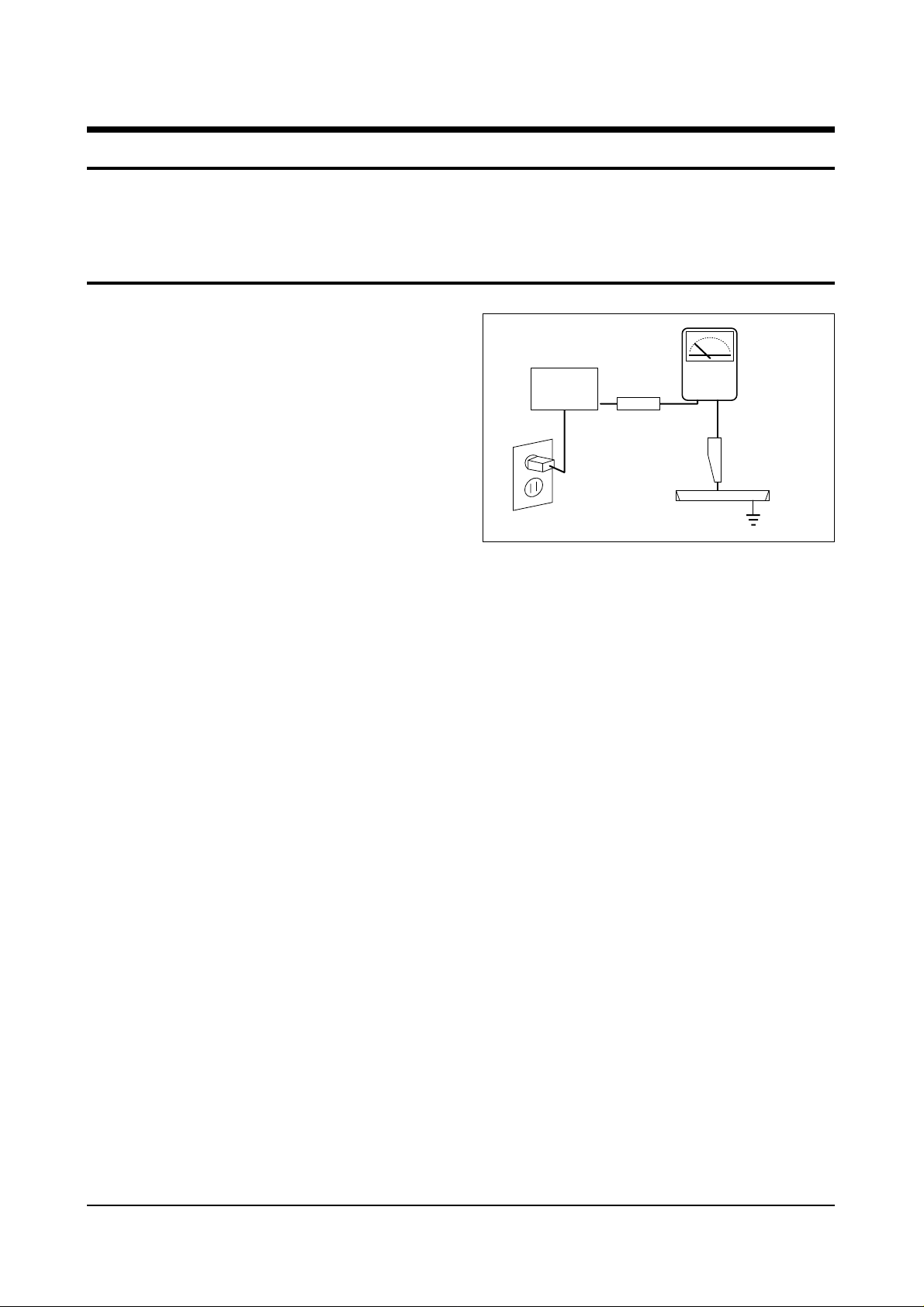
4. Leakage Current Hot Check (Figure 1-1):
Warning: Do not use an isolation
transformer during this test. Use a leakagecurrent tester or a metering system that
complies with American National Standards
Institute (ANIS C101.1, Leakage Current for
Appliances), and Underwriters Laboratories
(UL Publication UL1410, 59.7).
5. With the unit completely reassembled, plug
the AC line cord directly into the power
outlet. With the unit’s AC switch first in the
ON position and then OFF, measure the
current between a known earth ground (metal
water pipe, conduit, etc.) and all exposed
metal parts, including: antennas, handle
brackets, metal cabinets, screwheads and
control shafts. The current measured should
not exceed 0.5 milliamp. Reverse the powerplug prongs in the AC outlet and repeat the
test.
Fig. 1-1 AC Leakage Test
6. Antenna Cold Check:
With the unit’s AC plug disconnected from the
AC source, connect an electrical jumper across
the two AC prongs. Connect one lead of the
ohmmeter to an AC prong. Connect the other
lead to the coaxial connector.
7. X-ray Limits:
The picture tube is especially designed to prohibit X-ray emissions. To ensure continued
X-ray protection, replace the picture tube only
with one that is the same type as the original.
Carefully reinstall the picture tube shields and
mounting hardware; these also provide X-ray
protection.
8. High Voltage Limits:
High voltage must be measured each time servicing is done on the B+, horizontal deflection
or high voltage circuits. Correct operation of
the X-ray protection circuits must be
reconfirmed whenever they are serviced.
(X-ray protection circuits also may be called
“horizontal disable” or “hold-down”.)
Heed the high voltage limits. These include
the X–ray Protection Specifications Label, and
the Product Safety and X-ray Warning Note on
the service data schematic.
Precautions
Samsung Electronics 1-1
LEAKAGE
CURRENT
TESTER
DEVICE
UNDER
TEST
TEST ALL
EXPOSED METAL
SURFACES
2-WIRE CORD
ALSO TEST WITH
PLUG REVERSED
(USING AC ADAPTER
PLUG AS REQUIRED)
EARTH
GROUND
(READING SHOULD
NOT BE ABOVE
0.5mA)
Follow these safety, servicing and ESD precautions to prevent damage and protect against potential
hazards such as electrical shock and X-rays.
Page 3

1-1 Safety Precautions (Continued)
9. High voltage is maintained within specified
limits by close-tolerance, safety-related
components and adjustments. If the high
voltage exceeds the specified limits, check
each of the special components.
10. Design Alteration Warning:
Never alter or add to the mechanical or
electrical design of this unit. Example: Do not
add auxiliary audio or video connectors. Such
alterations might create a safety hazard. Also,
any design changes or additions will void the
manufacturer’s warranty.
11. Hot Chassis Warning:
Some TV receiver chassis are electrically
connected directly to one conductor of the AC
power cord. If an isolation transformer is not
used, these units may be safely serviced only
if the AC power plug is inserted so that the
chassis is connected to the ground side of the
AC source.
To confirm that the AC power plug is inserted
correctly, do the following: Using an AC
voltmeter, measure the voltage between the
chassis and a known earth ground. If the
reading is greater than 1.0V, remove the AC
power plug, reverse its polarity and reinsert.
Re-measure the voltage between the chassis
and ground.
12. Some TV chassis are designed to operate with
85 volts AC between chassis and ground,
regardless of the AC plug polarity. These units
can be safely serviced only if an isolation
transformer inserted between the receiver and
the power source.
13. Some TV chassis have a secondary ground
system in addition to the main chassis ground.
This secondary ground system is not
isolated from the AC power line. The two
ground systems are electrically separated by
insulating material that must not be defeated
or altered.
14. Components, parts and wiring that appear to
have overheated or that are otherwise
damaged should be replaced with parts that
meet the original specifications. Always
determine the cause of damage or overheating, and correct any potential hazards.
15. Observe the original lead dress, especially
near the following areas: Antenna wiring,
sharp edges, and especially the AC and high
voltage power supplies. Always inspect for
pinched, out-of-place, or frayed wiring. Do
not change the spacing between components
and the printed circuit board. Check the AC
power cord for damage. Make sure that leads
and components do not touch thermally hot
parts.
16. Picture Tube Implosion Warning:
The picture tube in this receiver employs
“integral implosion” protection. To ensure
continued implosion protection, make sure
that the replacement picture tube is the same
as the original.
17. Do not remove, install or handle the picture
tube without first putting on shatterproof
goggles equipped with side shields. Never
handle the picture tube by its neck. Some
“in-line” picture tubes are equipped with a
permanently attached deflection yoke; do not
try to remove such “permanently attached”
yokes from the picture tube.
18. Product Safety Notice:
Some electrical and mechanical parts have
special safety-related characteristics which
might not be obvious from visual inspection.
These safety features and the protection they
give might be lost if the replacement component differs from the original—even if the
replacement is rated for higher voltage,
wattage, etc.
Components that are critical for safety are
indicated in the circuit diagram by shading,
( ) or ( ).
Use replacement components that have the
same ratings, especially for flame resistance
and dielectric strength specifications.
A replacement part that does not have the
same safety characteristics as the original
might create shock, fire or other hazards.
Precautions
1-2 Samsung Electronics
!
Page 4

1-2 Servicing Precautions
1. Servicing precautions are printed on the
cabinet. Follow them.
2. Always unplug the unit’s AC power cord from
the AC power source before attempting to: (a)
Remove or reinstall any component or
assembly, (b) Disconnect an electrical plug or
connector, (c) Connect a test component in
parallel with an electrolytic capacitor.
3. Some components are raised above the printed
circuit board for safety. An insulation tube or
tape is sometimes used. The internal wiring is
sometimes clamped to prevent contact with
thermally hot components. Reinstall all such
elements to their original position.
4. After servicing, always check that the screws,
components and wiring have been correctly
reinstalled. Make sure that the portion around
the serviced part has not been damaged.
5. Check the insulation between the blades of the
AC plug and accessible conductive parts
(examples: metal panels, input terminals and
earphone jacks).
6. Insulation Checking Procedure: Disconnect the
power cord from the AC source and turn the
power switch ON. Connect an insulation
resistance meter (500V) to the blades of the AC
plug.
The insulation resistance between each blade
of the AC plug and accessible conductive parts
(see above) should be greater than 1 megohm.
7. Never defeat any of the B+ voltage interlocks.
Do not apply AC power to the unit (or any of
its assemblies) unless all solid-state heat sinks
are correctly installed.
8. Always connect a test instrument’s ground
lead to the instrument chassis ground before
connecting the positive lead; always remove
the instrument’s ground lead last.
9. When some parts inside the optical engine
(except lamp) are damaged, replace the whole
optical engine.
Precautions
Samsung Electronics 1-3
Warning 1 : First read the “Safety Precautions” section of this manual. If some unforeseen circumstance creates a
conflict between the servicing and safety precautions, always follow the safety precautions.
Warning 2 : An electrolytic capacitor installed with the wrong polarity might explode.
Page 5

1-3 Precautions for Electrostatically Sensitive Devices (ESDs)
1. Some semiconductor (“solid state”) devices
are easily damaged by static electricity. Such
components are called Electrostatically
Sensitive Devices (ESDs); examples include
integrated circuits and some field-effect
transistors. The following techniques will
reduce the occurrence of component damage
caused by static electricity.
2. Immediately before handling any semicon
ductor components or assemblies, drain the
electrostatic charge from your body by
touching a known earth ground. Alternatively,
wear a discharging wrist-strap device. (Be
sure to remove it prior to applying power—
this is an electric shock precaution.)
3. After removing an ESD-equipped assembly,
place it on a conductive surface such as
aluminum foil to prevent accumulation of
electrostatic charge.
4. Do not use freon-propelled chemicals. These
can generate electrical charges that damage
ESDs.
5. Use only a grounded-tip soldering iron when
soldering or unsoldering ESDs.
6. Use only an anti-static solder removal device.
Many solder removal devices are not rated as
“anti-static”; these can accumulate sufficient
electrical charge to damage ESDs.
7. Do not remove a replacement ESD from its
protective package until you are ready to
install it. Most replacement ESDs are
packaged with leads that are electrically
shorted together by conductive foam,
aluminum foil or other conductive materials.
8. Immediately before removing the protective
material from the leads of a replacement ESD,
touch the protective material to the chassis or
circuit assembly into which the device will be
installed.
9. Minimize body motions when handling
unpackaged replacement ESDs. Motions such
as brushing clothes together, or lifting a foot
from a carpeted floor can generate enough
static electricity to damage an ESD.
Precautions
1-4 Samsung Electronics
Page 6

Reference Information
Samsung Electronics 2-1
2. Reference Information
2-1 Tables of Abbreviations and Acronyms
A
Ah
Å
dB
dBm
°C
°F
°K
F
G
GHz
g
H
Hz
h
ips
kWh
kg
kHz
kΩ
km
km/h
kV
kVA
kW
I
MHz
Ampere
Ampere-hour
Angstrom
Decibel
Decibel Referenced to One
Milliwatt
Degree Celsius
Degree Fahrenheit
degree Kelvin
Farad
Gauss
Gigahertz
Gram
Henry
Hertz
Hour
Inches Per Second
Kilowatt-hour
Kilogram
Kilohertz
Kilohm
Kilometer
Kilometer Per Hour
Kilovolt
Kilovolt-ampere
Kilowatt
Liter
Megahertz
MV
MW
MΩ
m
µA
µF
µH
µm
µs
µW
mA
mg
mH
mI
mm
ms
mV
nF
Ω
pF
Ib
rpm
rps
s
V
VA
W
Wh
Megavolt
Megawatt
Megohm
Meter
Microampere
Microfarad
Microhenry
Micrometer
Microsecond
Microwatt
Milliampere
Milligram
Millihenry
Milliliter
Millimeter
Millisecond
Millivolt
Nanofarad
Ohm
Picofarad
Pound
Revolutions Per Minute
Revolutions Per Second
Second (Time)
Volt
Volt-ampere
Watt
Watt-hour
Table 2-1 Abbreviations
Page 7

Reference Information
2-2 Samsung Electronics
Table 2-2 Table of Acronyms
ABL
AC
ACC
AF
AFC
AFT
AGC
AM
ANSI
APC
APC
A/V
AVC
BAL
BPF
B-Y
CATV
CB
CCD
CCTV
Ch
CRT
CW
DC
DVM
EIA
ESD
ESD
FBP
FBT
FF
FM
FS
GND
G-Y
H
HF
HI-FI
IC
IC
IF
Automatic Brightness Limiter
Alternating Current
Automatic Chroma Control
Audio Frequency
Automatic Frequency Control
Automatic Fine Tuning
Automatic Gain Control
Amplitude Modulation
American National Standards Institute
Automatic Phase Control
Automatic Picture Control
Audio-Video
Automatic Volume Control
Balance
Bandpass Filter
Blue-Y
Community Antenna Television (Cable TV)
Citizens Band
Charge Coupled Device
Closed Circuit Television
Channel
Cathode Ray Tube
Continuous Wave
Direct Current
Digital Volt Meter
Electronics Industries Association
Electrostatic Discharge
Electrostatically Sensitive Device
Feedback Pulse
Flyback Transformer
Flip-Flop
Frequency Modulation
Fail Safe
Ground
Green-Y
High
High-Frequency
High Fidelity
Inductance-Capacitance
Integrated Circuit
Intermediate Frequency
I/O
L
L
LED
LF
MOSFET
MTS
NAB
NEC
NTSC
OSD
PCB
PLL
PWM
QIF
R
RC
RF
R-Y
SAP
SAW
SIF
SMPS
S/N
SW
TP
TTL
TV
UHF
UL
UV
VCD
VCO
VCXO
VHF
VIF
VR
VTR
VTVM
TR
Input/output
Left
Low
Light Emitting Diode
Low Frequency
Metal-Oxide-Semiconductor-Field-Effect-Tr
Multi-channel Television Sound
National Association of Broadcasters
National Electric Code
National Television Systems Committee
On Screen Display
Printed Circuit Board
Phase-Locked Loop
Pulse Width Modulation
Quadrature Intermediate Frequency
Right
Resistor & Capacitor
Radio Frequency
Red-Y
Second Audio Program
Surface Acoustic Wave(Filter)
Sound Intermediate Frequency
Switching Mode Power Supply
Signal/Noise
Switch
Test Point
Transistor Transistor Logic
Television
Ultra High Frequency
Underwriters Laboratories
Ultraviolet
Variable-Capacitance Diode
Voltage Controlled Oscillator
Voltage Controlled Crystal Oscillator
Very High Frequency
Video Intermediate Frequency
Variable Resistor
Video Tape Recorder
Vacuum Tube Voltmeter
Transistor
Page 8

IC507
IC665
IC902
IC103
ICS801
ICS802
IC701/IC702
IC703
IC704
IC705
ICP101
ICP102
ICP103
ICP105
IC201
IC471
ICZ104,ICZ103
IC301
IC801
IC802
IC804
IC806
IC501/IC531/IC561
ICT01
ICT02
ICT04
ICT05
Block NameNo. IC Location IC Name
IC Line-Up
Reference Information
Samsung Electronics 2-3
2-2 IC Line Up
MAIN
TERMINAL BOARD
PIP
HV MODULE
CONVERGENCE
SUB
CRT
TTX
1
2
3
4
5
6
7
8
TDA8601
TDA7265
KSC24C08
TDA9810
TNY253P
PS2561
TDA6920
PCF8574P
TDA8601
4052
TDA9160A
TDA9815
PAP102
SDA9189X
SDA9187
TL494CN
STK392-040
LA7845
STR-F6656
SVD001
SE110N
PS2561
TDA6111Q
SDA5457
TEA5114
24C04
74HC32
Page 9

Reference Information
2-4 Samsung Electronics
9
10
11
Block NameNo. IC Location IC Name
Table 2 - 3 IC Line - Up (Continued)
FORMAT-CONVERTER
PROSCAN
DOLBY-SOUND
IC01
IC02
IC03
IC04
ICP101
ICP103
ICP301
ICP302
ICP401
ICP501
ICP601
ICP901
IC601
IC604/ICD602
ICD601
FS310KBC
72V161621
Z9021106PSC
24C02
VPC3215C
CIP3250A
SDA9400
4931
SDA9280
CXA2101AQ
SDA9361
7533
MSP3410D
TL062CDT
DPL3519A
Page 10
Reference Information
Samsung Electronics 2-5
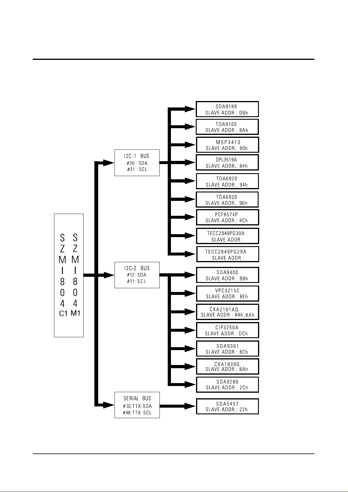
2-3 MICOM IIC BUS LINE -UP
Page 11

Specifications
Samsung Electronics 3-1
3. Specification
Broadcasting System
Scanning System
Tuning Range
Antenna Impedance
Intermediate Frequency
Sound Output
Rated Voltage
W/B Coordinates
High Voltage
FUSE
Power Consumption
PAL
100Hz
VHF : CH2 ~ CH13
UHF : CH14 ~ CH69
Cable : CH1, CH14 ~ CH125
75 ohm Unbalanced
Video : 38.9 [MHz]
Sound : 33.4 [MHz]
STD : 20W
FULL MAX : 22W
AC100~260 [V] 50/60[Hz], AC220[V] 50/60[Hz]
43J5 Hx : 272 Hy : 260 Y : 7.0
Lx : 245 Ly : 225 Y : 0.16
53J5 Hx : 272 Hy : 265 Y : 6.00
Lx : 255 Ly : 230 Y : 0.16
61J5 Hx : 278 Hy : 282 Y : 3.50
Lx : 265 Ly: 233 Y : 0.20
43J8 Hx : 272 Hy : 260 Y : 7.0
Lx : 245 Ly : 225 Y : 0.16
54J8 Hx : 272 Hy : 265 Y : 6.00
Lx : 255 Ly : 230 Y : 0.16
62J8 Hx : 278 Hy : 282 Y : 3.50
Lx : 265 Ly: 233 Y : 0.20
31.5 [KV]
250[V] 6.3[A]
CODE NO : 3801-001007
285W
Page 12

Alignment and Adjustments
Samsung Electronics 4-1
4. Alignment and Adjustments
4-1 When entering the service mode:
1. Turn on the TV and then select “STANDARD”on the picture adjustment mode.
2. Turn off the TV (STAND-BY).
3. Enter the service mode by pressing the remote control keys in the following sequence :
DISPLAY→ΜΕΝU→MUTE →Power On
Note : If necessary, re-do steps 1~3.
Initial display when the service mode is switched.
SERVICE MODE
GEOMETRICS
PICTURE
PICTURE2
PIP
OPTIONS
RESET
1. When a RF signal is received
MAIN MENU
ZOOM
COMPRESS
FREEZE
SET UP
RESET
EXIT
2. When the PC mode is received
(Press to )
F.MENUF.MENU
Page 13

Alignment and Adjustments
4-2 Samsung Electronics
MAIN MENU MENU DISPLAY
CH UP/DOWN Select item by moving cursor
VOL UP/DOWN Decrease or increase the adjustment values
3. Service Mode Control Keys
Note : The PC mode can be switched to the service mode by pressing the F.Mode Key (only
on the factory remote control).
Page 14

Alignment and Adjustments
Samsung Electronics 4-3
ITEM
FUNCTION INITIAL VALUE
ITEM
FUNCTION INITIAL VALUE
PAL (43J5)
VS
VA
VL
VSC
HS
HA
PPH
PAM
UPC
V-SHIFT
V-SIZE
V-LINEAR
V-S-COLOR
H-SHIFT
H-SIZE
PIN-PHASE
PIN-AMP
UP-CORR
GEOMETRIC(PAL/NTSC)
PICTURE
PICTURE2
SBR
RDR
GDR
BDR
RCT
GCT
SHC
R-R
R-B
G-R
G-B
SCN
SCR
HWD
HTM
SHP
SUB-BRIGHT
R-DRIVE
G-DRIVE
B-DRIVE
R-CUT OFF
G-CUT OFF
SUB-HUE
R-Y AXIS R-Y
R-Y AXIS R-Y
R-Y AXIS R-Y
R-Y AXIS R-Y
SUB-CONTRAST
SUB-COLOR
HSYNC WIDTH
HSYNC-TIME-MASK
SUB-SHARPNESS
106/124
60/76(Variable)
114
104
73/77
78/86(Variable)
143/180
70
128
20(Variable)
22(Variable)
31
37(Variable)
9(Variable)
31
7
3
7
15
2
7(Variable)
15
1
1
3
LOC
HEH
VE
VAN
VBO
HSP
--
--
--
LO-CORR
H-EHT
V-EHT
V-ANGLE
V-BOW
H-SYNC-PHASE
128
0
0
124
128
138
0
0
0
BCT
GAM
ABM
ATH
PYD
SYD
B-CUT OFF
GAMMA LEVEL
ABL MODE
ABL Threshold
PAL/NT Y/C DELAY
SECAM Y/C DELAY
31(Variable)
12
1
1
10
10
SFO
LTI
CTI
POV
VML
VMD
DCT
DNP
BPF
HPF
SHARPNESS-FO
LUMINANCE
CHROMINANCE
PRE-OVERSHOOT
VM-LEVEL
VM-DELAY
DC-TRAN
AUTO PEDESTAL
BAND PASS FILTER
HIGH PASS FILTER
2
2
1
3
2
3
3
3
12
10
PIP
PCN
PHP
PVP
CONTRAST
POS-HOR
POS-VER
8(Variable)
55(Variable)
27(Variable)
OPTION
LANGUAGE
TTX
LNA
OFF, WEST/ARABIC, EAST/FARSI
ON,OFF
PC
SCART2
THAI
ON, OFF
OFF, TV OUT, MONITOR OUT
ON, OFF
MULTI-12
MidEast
Asia
Russia
M. Europe
Eng, Arab, French, Thai, Russian, Croatian, Polish, Turkish, Hungaran, Iran, Pakistan, Hindi
Eng, Arab, French, Turkish, Iran, Pakistan
Eng, Thai, Hindi
Eng, Russia
Eng, Croatian, Polish, Hungaran
Page 15

Alignment and Adjustments
4-4 Samsung Electronics
ITEM
FUNCTION INITIAL VALUE
ITEM
FUNCTION INITIAL VALUE
PAL (53J5)
VS
VA
VL
VSC
HS
HA
PPH
PAM
UPC
V-SHIFT
V-SIZE
V-LINEAR
V-S-COLOR
H-SHIFT
H-SIZE
PIN-PHASE
PIN-AMP
UP-CORR
GEOMETRIC(PAL/NTSC)
PICTURE
PICTURE2
SBR
RDR
GDR
BDR
RCT
GCT
SHC
R-R
R-B
G-R
G-B
SCN
SCR
HWD
HTM
SHP
SUB-BRIGHT
R-DRIVE
G-DRIVE
B-DRIVE
R-CUT OFF
G-CUT OFF
SUB-HUE
R-Y AXIS R-Y
R-Y AXIS R-Y
R-Y AXIS R-Y
R-Y AXIS R-Y
SUB-CONTRAST
SUB-COLOR
HSYNC WIDTH
HSYNC-TIME-MASK
SUB-SHARPNESS
106/124
72/83(Variable)
114
104
73/77
79/86(Variable)
143/180
70
128
19(Variable)
15(Variable)
31
29(Variable)
17(Variable)
31
7
3
7
15
2
13(Variable)
15
1
1
3
LOC
HEH
VE
VAN
VBO
HSP
--
--
--
LO-CORR
H-EHT
V-EHT
V-ANGLE
V-BOW
H-SYNC-PHASE
128
0
0
124
128
138
0
0
0
BCT
GAM
ABM
ATH
PYD
SYD
B-CUT OFF
GAMMA LEVEL
ABL MODE
ABL THRESHOLD
PAL/NT Y/C DELAY
SECAM Y/C DELAY
28(Variable)
12
1
1
10
10
SFO
STI
CTI
POV
VML
VMD
DCT
DNP
BPF
HPF
SHARPNESS-FO
LUMINANCE
CHROMINANCE
PRE-OVERSHOOT
VM-LEVEL
VM-DELAY
DC-TRAN
AUTO PEDESTAL
BAND PASS FILTER
HIGH PASS FILTER
2
2
1
3
2
3
3
3
12
10
PIP
PCN
PHP
PVP
CONTRAST
POS-HOR
POS-VER
8(Variable)
55(Variable)
27(Variable)
OPTION
LANGUAGE
TTX
LNA
OFF, WEST/ARABIC, EAST/FARSI
ON,OFF
PC
SCART2
THAI
ON, OFF
OFF, TV OUT, MONITOR OUT
ON, OFF
MULTI-12
MidEast
Asia
Russia
M. Europe
Eng, Arab, French, Thai, Russian, Croatian, Polish, Turkish, Hungaran, Iran, Pakistan, Hindi
Eng, Arab, French, Turkish, Iran, Pakistan
Eng, Thai, Hindi
Eng, Russia
Eng, Croatian, Polish, Hungaran
Page 16

Alignment and Adjustments
Samsung Electronics 4-5
ITEM
FUNCTION INITIAL VALUE
ITEM
FUNCTION INITIAL VALUE
PAL (61J5)
VS
VA
VL
VSC
HS
HA
PPH
PAM
UPC
V-SHIFT
V-SIZE
V-LINEAR
V-S-COLOR
H-SHIFT
H-SIZE
PIN-PHASE
PIN-AMP
UP-CORR
GEOMETRIC(PAL/NTSC)
PICTURE
PICTURE2
SBR
RDR
GDR
BDR
RCT
GCT
SHC
R-R
R-B
G-R
G-B
SCN
SCR
HWD
HTM
SHP
SUB-BRIGHT
R-DRIVE
G-DRIVE
B-DRIVE
R-CUT OFF
G-CUT OFF
SUB-HUE
R-Y AXIS R-Y
R-Y AXIS R-Y
R-Y AXIS R-Y
R-Y AXIS R-Y
SUB-CONTRAST
SUB-COLOR
HSYNC WIDTH
HSYNC-TIME-MASK
SUB-SHARPNESS
106/124
90/94(Variable)
114
104
73/77
62/74(Variable)
143/180
70
128
25(Variable)
8(Variable)
31
32(Variable)
16(Variable)
31
7
3
7
15
2
13(Variable)
15
1
1
3
LOC
HEH
VE
VAN
VBO
HSP
--
--
--
LO-CORR
H-EHT
V-EHT
V-ANGLE
V-BOW
H-SYNC-PHASE
128
0
0
124
128
138
0
0
0
BCT
GAM
ABM
ATH
PYD
SYD
B-CUT OFF
GAMMA LEVEL
ABL MODE
ABL Threshold
PAL/NT Y/C DELAY
SECAM Y/C DELAY
23(Variable)
12
1
1
10
10
SFO
STI
CTI
POV
VML
VMD
DCT
DNP
BPF
HPF
SHARPNESS-FO
LUMINANCE
CHROMINANCE
PRE-OVERSHOOT
VM-LEVEL
VM-DELAY
DC-TRAN
AUTO PEDESTAL
BAND PASS FILTER
HIGH PASS FILTER
2
2
1
3
2
3
3
3
12
10
PIP
PCN
PHP
PVP
CONTRAST
POS-HOR
POS-VER
8(Variable)
55(Variable)
27(Variable)
OPTION
LANGUAGE
TTX
LNA
OFF, WEST/ARABIC, EAST/FARSI
ON,OFF
PC
SCART2
THAI
ON, OFF
OFF, TV OUT, MONITOR OUT
ON, OFF
MULTI-12
MidEast
Asia
Russia
M. Europe
Eng, Arab, French, Thai, Russian, Croatian, Polish, Turkish, Hungaran, Iran, Pakistan, Hindi
Eng, Arab, French, Turkish, Iran, Pakistan
Eng, Thai, Hindi
Eng, Russia
Eng, Croatian, Polish, Hungaran
Page 17

Alignment and Adjustments
4-6 Samsung Electronics
ITEM
FUNCTION INITIAL VALUE
ITEM
FUNCTION INITIAL VALUE
PAL (43J8)
VS
VA
VL
VSC
HS
HA
PPH
PAM
UPC
V-SHIFT
V-SIZE
V-LINEAR
V-S-COLOR
H-SHIFT
H-SIZE
PIN-PHASE
PIN-AMP
UP-CORR
GEOMETRIC(PAL/NTSC)
PICTURE
PICTURE2
SBR
RDR
GDR
BDR
RCT
GCT
SHC
R-R
R-B
G-R
G-B
SCN
SCR
HWD
HTM
SHP
SUB-BRIGHT
R-DRIVE
G-DRIVE
B-DRIVE
R-CUT OFF
G-CUT OFF
SUB-HUE
R-Y AXIS R-Y
R-Y AXIS R-Y
R-Y AXIS R-Y
R-Y AXIS R-Y
SUB-CONTRAST
SUB-COLOR
HSYNC WIDTH
HSYNC-TIME-MASK
SUB-SHARPNESS
106/124
60/76(Variable)
114
104
73/77
78/86(Variable)
143/180
70
128
20(Variable)
22(Variable)
31
37(Variable)
9(Variable)
31
7
3
7
15
2
7(Variable)
15
1
1
3
LOC
HEH
VE
VAN
VBO
HSP
--
--
--
LO-CORR
H-EHT
V-EHT
V-ANGLE
V-BOW
H-SYNC-PHASE
128
0
0
124
128
138
0
0
0
BCT
GAM
ABM
ATH
PYD
SYD
B-CUT OFF
GAMMA LEVEL
ABL MODE
ABL Threshold
PAL/NT Y/C DELAY
SECAM Y/C DELAY
31(Variable)
12
1
1
10
10
SFO
LTI
CTI
POV
VML
VMD
DCT
DNP
BPF
HPF
SHARPNESS-FO
LUMINANCE
CHROMINANCE
PRE-OVERSHOOT
VM-LEVEL
VM-DELAY
DC-TRAN
AUTO PEDESTAL
BAND PASS FILTER
HIGH PASS FILTER
2
2
1
3
2
3
3
3
12
10
PIP
PCN
PHP
PVP
CONTRAST
POS-HOR
POS-VER
8(Variable)
55(Variable)
27(Variable)
OPTION
LANGUAGE
TTX
LNA
OFF, WEST/ARABIC, EAST/FARSI
ON,OFF
PC
SCART2
THAI
ON, OFF
OFF, TV OUT, MONITOR OUT
ON, OFF
MULTI-12
MidEast
Asia
Russia
M. Europe
Eng, Arab, French, Thai, Russian, Croatian, Polish, Turkish, Hungaran, Iran, Pakistan, Hindi
Eng, Arab, French, Turkish, Iran, Pakistan
Eng, Thai, Hindi
Eng, Russia
Eng, Croatian, Polish, Hungaran
Page 18
Alignment and Adjustments
Samsung Electronics 4-7
ITEM
FUNCTION INITIAL VALUE
ITEM
FUNCTION INITIAL VALUE
PAL (54J8)
VS
VA
VL
VSC
HS
HA
PPH
PAM
UPC
V-SHIFT
V-SIZE
V-LINEAR
V-S-COLOR
H-SHIFT
H-SIZE
PIN-PHASE
PIN-AMP
UP-CORR
GEOMETRIC(PAL/NTSC)
PICTURE
PICTURE2
SBR
RDR
GDR
BDR
RCT
GCT
SHC
R-R
R-B
G-R
G-B
SCN
SCR
HWD
HTM
SHP
SUB-BRIGHT
R-DRIVE
G-DRIVE
B-DRIVE
R-CUT OFF
G-CUT OFF
SUB-HUE
R-Y AXIS R-Y
R-Y AXIS R-Y
R-Y AXIS R-Y
R-Y AXIS R-Y
SUB-CONTRAST
SUB-COLOR
HSYNC WIDTH
HSYNC-TIME-MASK
SUB-SHARPNESS
106/124
60/76(Variable)
114
104
73/77
78/86(Variable)
143/180
70
128
20(Variable)
22(Variable)
31
37(Variable)
9(Variable)
31
7
3
7
15
2
7(Variable)
15
1
1
3
LOC
HEH
VE
VAN
VBO
HSP
--
--
--
LO-CORR
H-EHT
V-EHT
V-ANGLE
V-BOW
H-SYNC-PHASE
128
0
0
124
128
138
0
0
0
BCT
GAM
ABM
ATH
PYD
SYD
B-CUT OFF
GAMMA LEVEL
ABL MODE
ABL Threshold
PAL/NT Y/C DELAY
SECAM Y/C DELAY
31(Variable)
12
1
1
10
10
SFO
LTI
CTI
POV
VML
VMD
DCT
DNP
BPF
HPF
SHARPNESS-FO
LUMINANCE
CHROMINANCE
PRE-OVERSHOOT
VM-LEVEL
VM-DELAY
DC-TRAN
AUTO PEDESTAL
BAND PASS FILTER
HIGH PASS FILTER
2
2
1
3
2
3
3
3
12
10
PIP
PCN
PHP
PVP
CONTRAST
POS-HOR
POS-VER
8(Variable)
55(Variable)
27(Variable)
OPTION
LANGUAGE
TTX
LNA
OFF, WEST/ARABIC, EAST/FARSI
ON,OFF
PC
SCART2
THAI
ON, OFF
OFF, TV OUT, MONITOR OUT
ON, OFF
MULTI-12
MidEast
Asia
Russia
M. Europe
Eng, Arab, French, Thai, Russian, Croatian, Polish, Turkish, Hungaran, Iran, Pakistan, Hindi
Eng, Arab, French, Turkish, Iran, Pakistan
Eng, Thai, Hindi
Eng, Russia
Eng, Croatian, Polish, Hungaran
Page 19

Alignment and Adjustments
4-8 Samsung Electronics
ITEM
FUNCTION INITIAL VALUE
ITEM
FUNCTION INITIAL VALUE
PAL (62J8)
VS
VA
VL
VSC
HS
HA
PPH
PAM
UPC
V-SHIFT
V-SIZE
V-LINEAR
V-S-COLOR
H-SHIFT
H-SIZE
PIN-PHASE
PIN-AMP
UP-CORR
GEOMETRIC(PAL/NTSC)
PICTURE
PICTURE2
SBR
RDR
GDR
BDR
RCT
GCT
SHC
R-R
R-B
G-R
G-B
SCN
SCR
HWD
HTM
SHP
SUB-BRIGHT
R-DRIVE
G-DRIVE
B-DRIVE
R-CUT OFF
G-CUT OFF
SUB-HUE
R-Y AXIS R-Y
R-Y AXIS R-Y
R-Y AXIS R-Y
R-Y AXIS R-Y
SUB-CONTRAST
SUB-COLOR
HSYNC WIDTH
HSYNC-TIME-MASK
SUB-SHARPNESS
106/124
90/94(Variable)
114
104
73/77
62/74(Variable)
143/180
70
128
25(Variable)
8(Variable)
31
32(Variable)
16(Variable)
31
7
3
7
15
2
13(Variable)
15
1
1
3
LOC
HEH
VE
VAN
VBO
HSP
--
--
--
LO-CORR
H-EHT
V-EHT
V-ANGLE
V-BOW
H-SYNC-PHASE
128
0
0
124
128
138
0
0
0
BCT
GAM
ABM
ATH
PYD
SYD
B-CUT OFF
GAMMA LEVEL
ABL MODE
ABL Threshold
PAL/NT Y/C DELAY
SECAM Y/C DELAY
23(Variable)
12
1
1
10
10
SFO
STI
CTI
POV
VML
VMD
DCT
DNP
BPF
HPF
SHARPNESS-FO
LUMINANCE
CHROMINANCE
PRE-OVERSHOOT
VM-LEVEL
VM-DELAY
DC-TRAN
AUTO PEDESTAL
BAND PASS FILTER
HIGH PASS FILTER
2
2
1
3
2
3
3
3
12
10
PIP
PCN
PHP
PVP
CONTRAST
POS-HOR
POS-VER
8(Variable)
55(Variable)
27(Variable)
OPTION
LANGUAGE
TTX
LNA
OFF, WEST/ARABIC, EAST/FARSI
ON,OFF
PC
SCART2
THAI
ON, OFF
OFF, TV OUT, MONITOR OUT
ON, OFF
MULTI-12
MidEast
Asia
Russia
M. Europe
Eng, Arab, French, Thai, Russian, Croatian, Polish, Turkish, Hungaran, Iran, Pakistan, Hindi
Eng, Arab, French, Turkish, Iran, Pakistan
Eng, Thai, Hindi
Eng, Russia
Eng, Croatian, Polish, Hungaran
Page 20
Alignment and Adjustments
Samsung Electronics 4-9
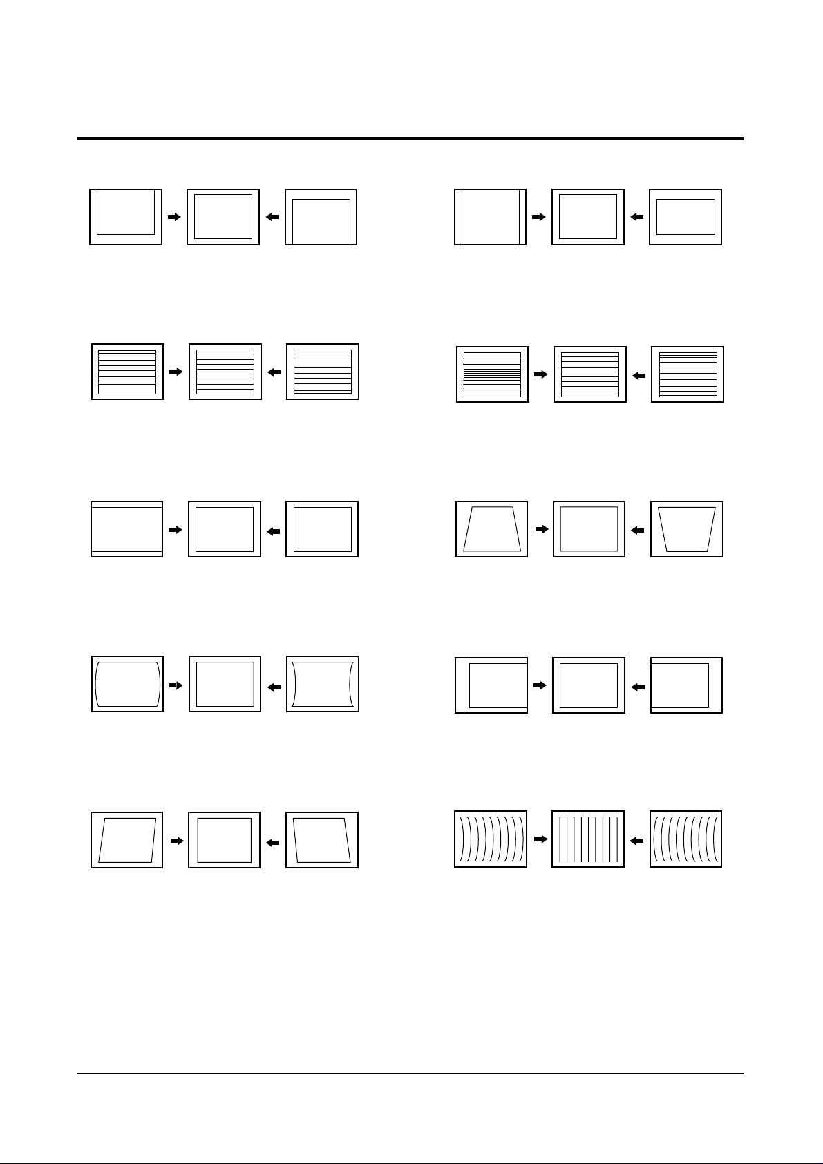
4-2 Screen Change (When adjusting I2C Bus Geometric items)
1 V SHIFT
6 V SIZE
2 V LINEARITY
3 H SIZE
4
PIN AMP
7 V - S - CORRECTION
8
PIN PHASE
9 H SHIFT
5 V ANGLE
10 V BOW
Page 21
Alignment and Adjustments
4-10 Samsung Electronics
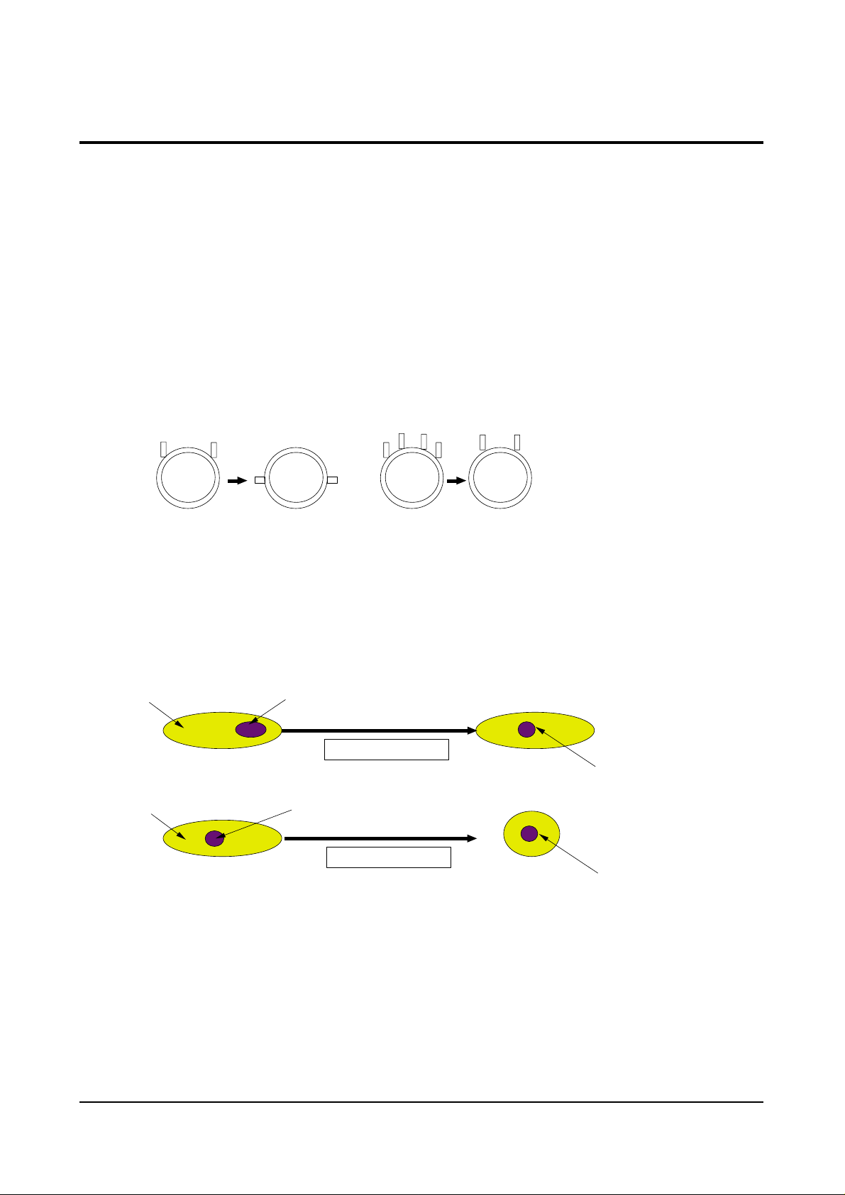
4-3 Beam Alignment
PRECAUTION
1. Input a crosshatch and dot pattern.
2. Select the “STANDARD” video mode.
3. Warm up the TV for at least 10 minutes.
4. Connect an audio oscillator to the pin jig between GT401~GT402 (located on the deflection
PCB) and GND.
5. Determine the ZERO-magnet area (using the beam-alignment CY)
6. Check the squarewave at the point where the focus is misaligned (Use an audio oscillator).
ADJUSTMENT
1. Cover the Red and Blue lenses.
2. Adjust the Green lens as shown in the figures below
3. Adjust the G-Focus until any light around the core disappears.
4. Cover the Green and Blue lenses.
5. Adjust the Red lens using the same method as with the Green lens.
6. Note: The Blue lens is not adjusted because its focus varies little (VM-coil is installed).
7. After the adjustments are completed, disconnect the jig pin connector.
(Creation of CPM Zero Magnet)
(Creation of the 2-pole/4-pole zero magnets)
G-FOCUS
(Varying G-Focus Pack)
G-FOCUS
(When VM 2-Pole Adjustment is completed)
CORE
Varying the 2-pole of VM
CORE
Varying the 4-pole of VM
(Positioning the Core in the Center)
(Adjust until the light around
the core becomes a circle)
Page 22

Alignment and Adjustments
Samsung Electronics 4-11
4-4 Other Adjustments
4-4-1 Screen Adjustment
1. Warm up the TV for at least 30 minutes.
2. Turn to the Video Mode (No Signal) using a
remote-control.
3. Connect an oscilloscope to RK,GK,BK.
4. Adjust the VR (VR501, VR531, VR561) screen
so that RK, GK, BK pulse is 20Vp-p each.
(Turn the R,G,B VR screen fully
counterclockwise in the area of each flyback
line.)
4-4-2 White Balance Adjustment
1. Select the “STANDARD” video mode.
2. Input 100% white pattern.
3. In the stand-by mode, press the remote-control
keys in the following sequence:
DISPLAY→ΜΕΝU→MUTE →Power On
4. Warm up the TV for at least 30 minutes.
5. Input a 10-step signal.
6. R-cut off, B-cut off, and G-cut off by pressing
the Volume +/- keys.
7. Adjust the low light with viewing the dark
side of the screen.
8. Select R-drive, G-drive, and B-drive by
pressing the Volume +/- keys.
9. Adjust the high light with viewing the light
side of the screen.
10. If necessary, redo adjustments 6~9.
11. Press the Menu key to exit.
4-4-3 Sub-Brightness Adjustment
1. Input a sub-brightness adjustment signal.
(TOSHIBA PATTERN)
2. In the stand-by mode, press the remote-control
keys in the following sequence :
DISPLAY→ΜΕΝU→MUTE →Power On
3. Select SBT by pressing the Volume +/- keys.
4. Adjust so that the 7th step on the right side of
the screen is not seen (Use the Volume +/keys).
5. Press the Menu key to exit.
4-4-4 High Voltage (31KV) Check
PRECAUTION
1. Input a lion head pattern.
2. Select “STANDARD” video mode.
3. Warm up the TV for at least 10 minutes.
4. Use a 1000:1 probe.
ADJUSTMENT
1. Connect the (+) terminal of the 1000:1 probe to
the high voltage distributor and the (-)
terminal to GND (located on the deflection
board).
2. Adjust VR471 (located on the deflection board)
so that the digital meter indicates
DC 31V ± 0.1V.
Page 23

Alignment and Adjustments
4-12 Samsung Electronics
4-4-5 F.S. (Fail Safe) Circuit Check
Note : The F.S. Circuit check must be performed
after servicing.
1. Turn on the TV.
2. Select the “STANDARD” video mode.
3. Short GT18, GT17 (located on the
Convergence PCB). Then, both sound and
picture disappear. (Note: Even if the shorted
terminals are removed, both sound and
picture do not appear. This proves the F.S.
circuit is working. )
4. To restore both sound and picture, turn off the
TV and reset it after about 30 seconds.
4-4-6 Static Focus Adjustment
PRECAUTION
1. Select the “STANDARD” video mode.
2. Input a crosshatch pattern.
3. Cover the lenses that are not being adjusted.
4. Connect a convergence jig and read data.
5. Adjust the lens for best focus.
(See Fig, 4-1, next page)
STATIC FOCUS (CONTINUED)
Vary the focus pack VR (Red, Blue) on the
front cabinet. Adjust the TV for best possible
focus around the center of the crosshatch
pattern, without losing overall screen balance.
Figure Crosshatch Pattern
Examine these points together.
4-4-7 Lens Focus Adjustment
PRECAUTIONS
1. Do this adjustment after the static focus
adjustment and the tilt adjustment.
2. Select the “STANDARD” video mode.
(Contrast:64, Brightness:32)
3. Input a crosshatch pattern.
ADJUSTMENT
1. Loosen the lens screws.
2. Cover the two lenses that are not being
adjusted.
3. Adjust the lens, observing the color aberration
vertically and horizontally within 3 blocks of
the center of the crosshatch pattern.
4. When the lens is turned clockwise, the color
aberration will change as follows:
Lens
Color Aberration Change
R Orange - Crimson
G Blue - Red
B Purple - Green
5. Green lens adjustment:
Set the lens at the point where Blue just
changes to Red. If the color aberration is
irregular throughout the picture screen, adjust
the lens to show Red color aberration
(approximately 1~3 mm area) within a 3-block
grid around the horizontal center-line. If the
color aberration is irregular, adjust the lens as
shown in the diagram below. (Accurate
alignment of Green is important for overall
color quality.)
6. Red lens adjustment
Set the Red lens at the point where Orange
becomes Crimson.
7. Blue lens adjustment
Set the Blue lens at the point where Purple
becomes Green.
P
L1
L2
RED ABERRATION
BLUE ABERRATION
L1, L2 < P
_
Fig. 4-1 Crosshatch Pattern.
Fig. 4-2 Color Aberration
Examine these points together
Page 24
Alignment and Adjustments
Samsung Electronics 4-13
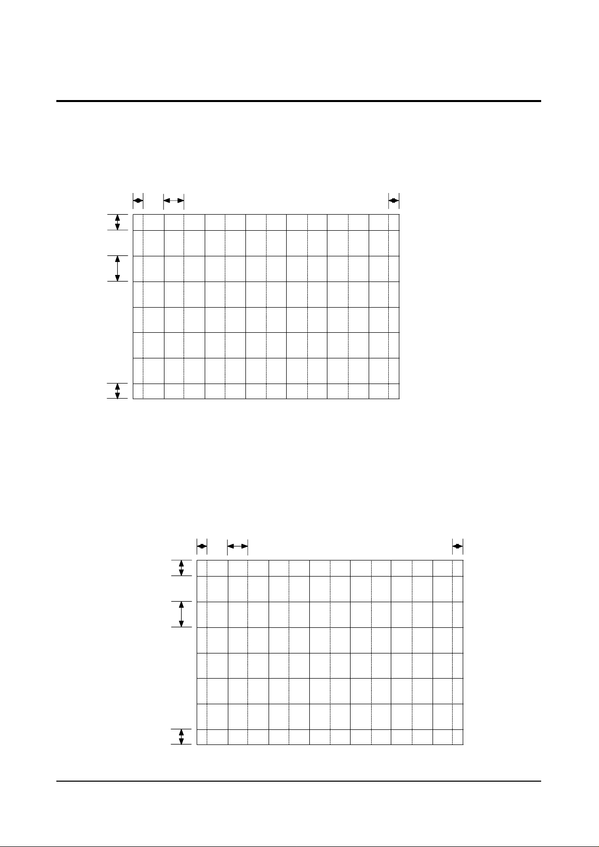
4-5 Screen-Jig
4-5-1 43J5 Convergence Jig Spec
4-5-2 53J5 Convergence Jig Spec
43J5 Screen Size : X 873, Y 655
16. 34mm 70. 03 mm
41.68mm
95.27mm
41.68mm
(X:374=7 2+30 12, Y:220=14 2+32 6)
*
*
*
*
16.34mm
53J5 Screen Size : X 1087, Y81 7
20.34mm 87.19mm 20.34mm
51.99mm
1
18.84mm
51.99mm
(X:374=7 2+30 12, Y:220=14 2+32 6)
*
*
*
*
Page 25
Alignment and Adjustments
4-14 Samsung Electronics
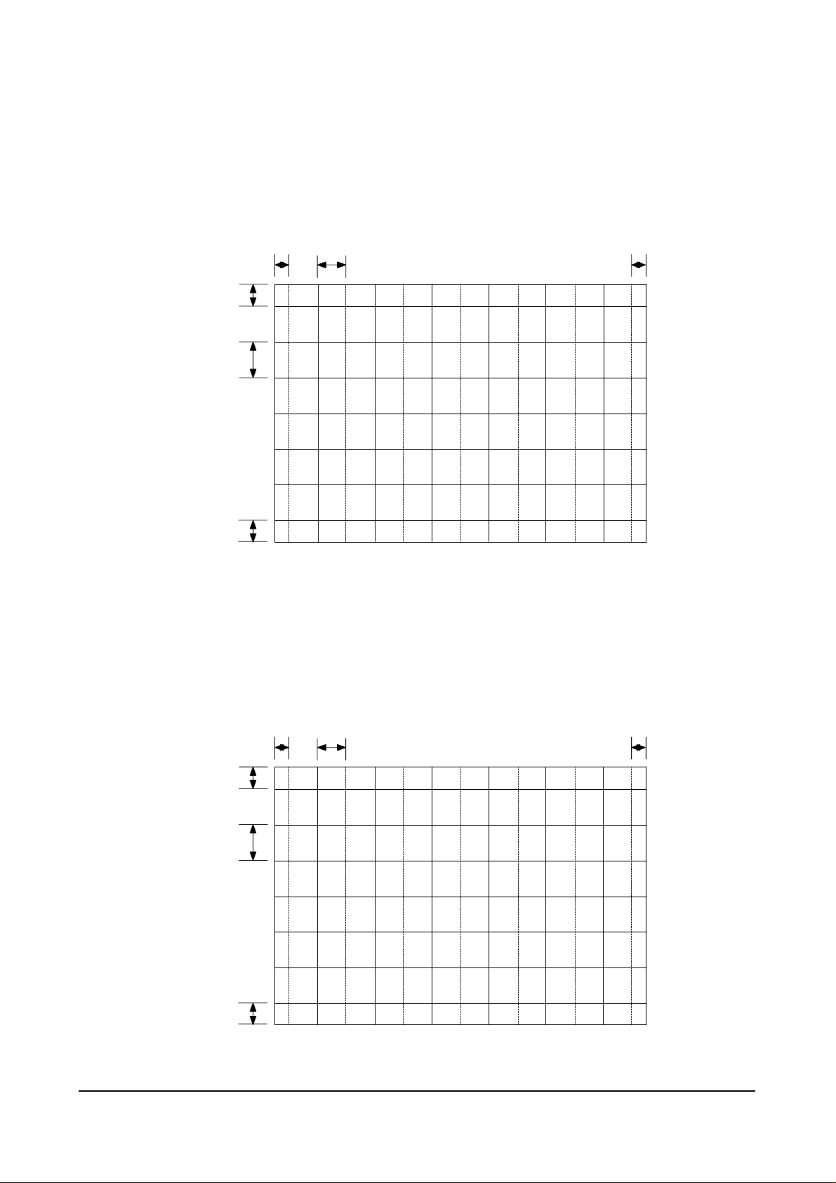
4-5-3 61J5 Convergence Jig Spec
4-5-4 43J8 Convergence Jig Spec
61J5 Screen Size : X 1253, Y 943
0
60.01mm
1
37.16mm
60.01mm
23.45mm 10 .51mm 23.45mm
(X:374=7 2+30 12, Y:220=14 2+32 6)
*
*
*
*
43J8 Screen Size : X Y
16. 55mm 70. 94 mm
42.38mm
96.86mm
42.38mm
884.4, 665.9
(X:374=7 2+30 12, Y:220=14 2+32 6)
*
*
*
*
16.55mm
Page 26
Alignment and Adjustments
Samsung Electronics 4-15
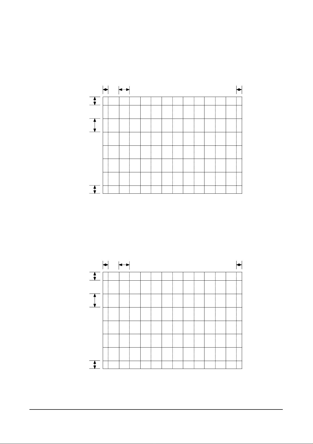
4-5-5 54J8 Convergence Jig Spec
4-5-6 62J8 Convergence Jig Spec
54J 8 Sc reen Size : X Y
20.58mm 88.19mm 20.58mm
52.68mm
1
20.42mm
52.68mm
1099.4,
(X:374=7 2+30 12, Y:220=14 2+32 6)
827.9
*
*
*
*
62J 8 Screen Si ze : X Y
23.57mm 10 .02mm 23.57mm
60.32mm
1
37.88mm
60.32mm
1259.4,
1
947.9
(X:374=7 2+30 12, Y:220=14 2+32 6)
*
*
*
*
Page 27
Alignment and Adjustments
4-16 Samsung Electronics
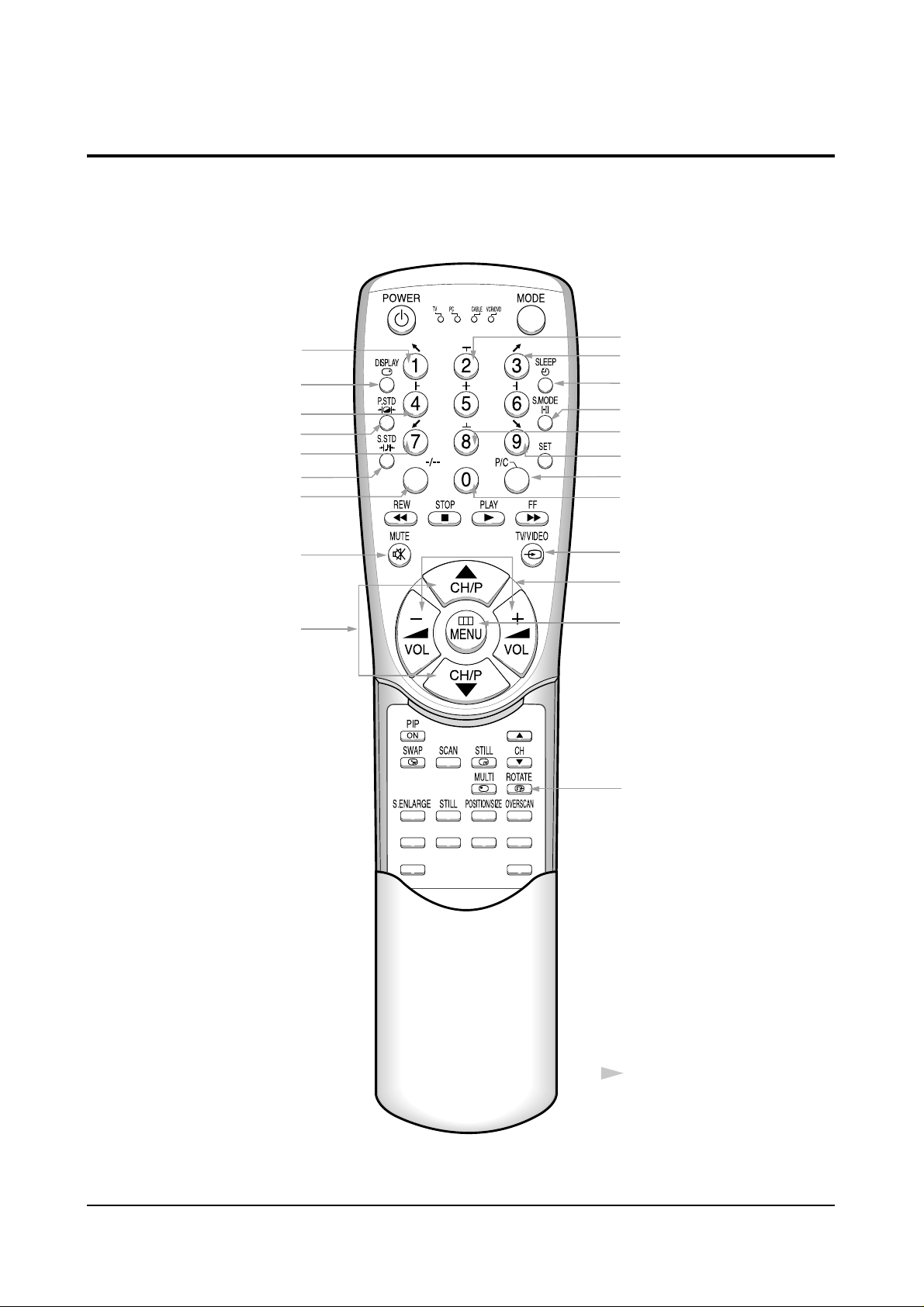
4-6 Remote Control for Servicing (Convergence Mode)
FACTORY
CONV.
ESCAPE
R/B
3SPEED
F.MENU
Factory Data Select Button
Last Data Save Button
Convergence Pattern Left Move Button
Save Button
G-Select
B-Select
B-Mute
G-Mute
Move Cursor Forward
Convergence Data
Increase, decrease button
Convergence Data Zero Button
Test/Normal
Line Shift
R-Select
Exit Button
R-Mute
Move Cursor Reverse
Convergence Picture
Move Button
Operation of remote
control may be affected
by bright artificial light
near to the TV set.
Convergence Pattern Right Move Button
Data Shift Button
(After PAL Adjustments are
Completed, Press to transmit
data to the NTSC mode)
H/V Direction Select Button
Page 28
Alignment and Adjustments
Samsung Electronics 4-17
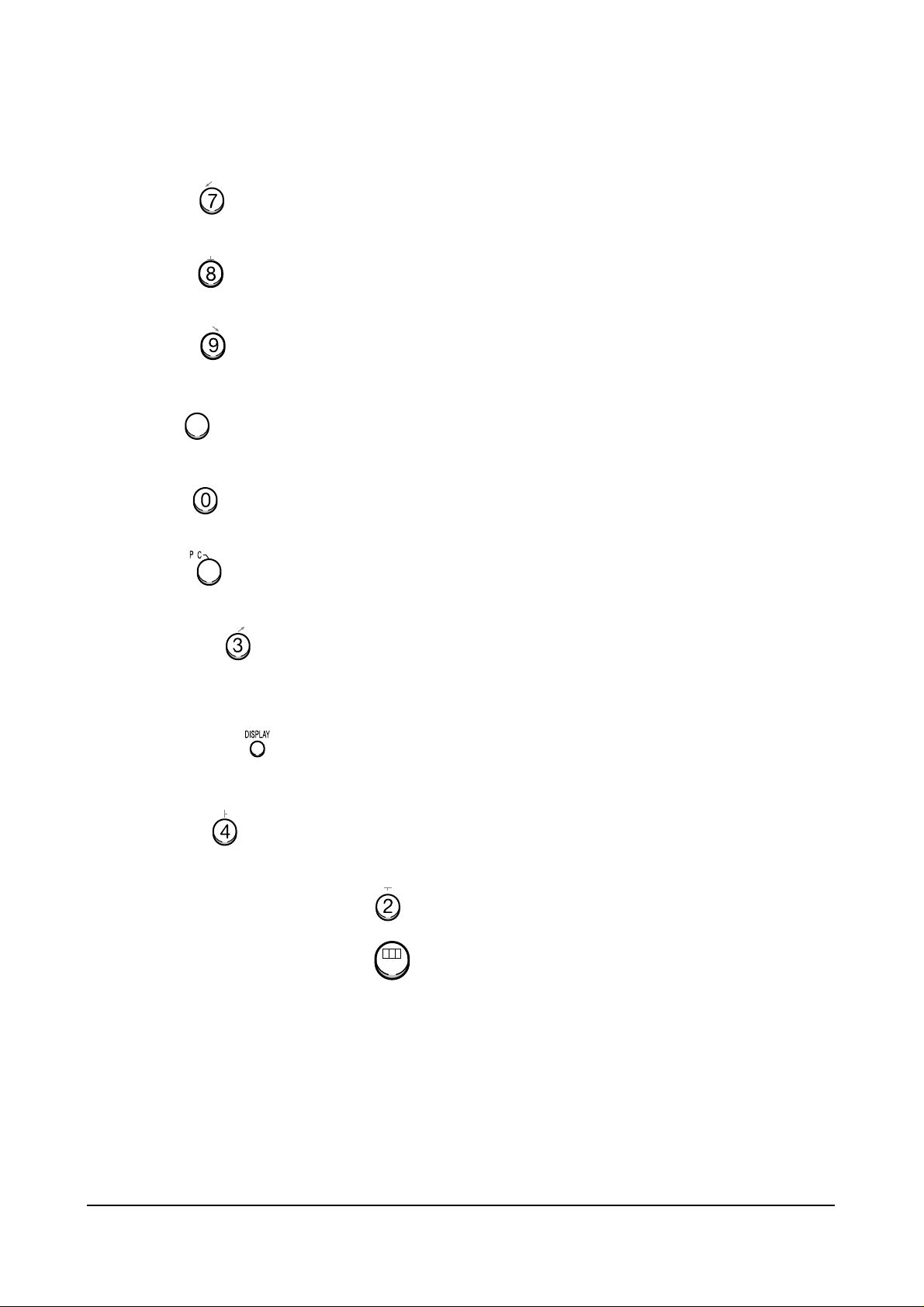
4-6-1 KEY Function
1. R-SELECT
Press to select RED color.
2. G-SELECT
Press to select GREEN color.
3. B-SELECT
Press to select BLUE color.
4. R-MUTE
Press to mute RED color.
5. G-MUTE
Press to mute GREEN color.
6. B-MUTE
Press to mute BLUE color.
7. CANCEL KEY
Press to revert to the previous data during the Convergence
Adjustment.
8. TEST/NORMAL
Press to check TV mode in the Convergence Mode.
9. LINE SHIFT
Press to move a line up/down or left/right.
10. FACTORY DATASELECT BUTTON
Press to call the factory default values.
11. H/V DIRECTION SELECT BUTTON
Press to switch the cursor direction horizontally or vertically.
/
MENUMENU
-/--
Page 29
Alignment and Adjustments
4-18 Samsung Electronics
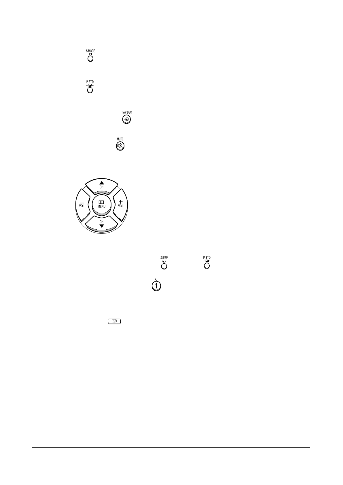
12. SAVE BUTTON
After the Convergence adjustments are completed, press to save data.
13. EXIT BUTTON
After the Convergence Adjustments are completed, press to exit to TV mode.
14. MOVE CURSOR FORWARD
Press to move the cursor right or down.
15. MOVE CURSOR REVERSE
Press to move the cursor left or up.
16. CONVERGENCE PICTURE MOVE BUTTON
17. CONVERGENCE PATTERN MOVE BUTTON
Press to move the convergence pattern left ( ) or right ( ) .
18. CONVERGENCE DATAZERO BUTTON
Press to zero the convergence correction data.
19. DATASHIFT BUTTON
Press to transmit data (PAL mode / NTSC mode).
ROTATE
Page 30
Alignment and Adjustments
Samsung Electronics 4-19
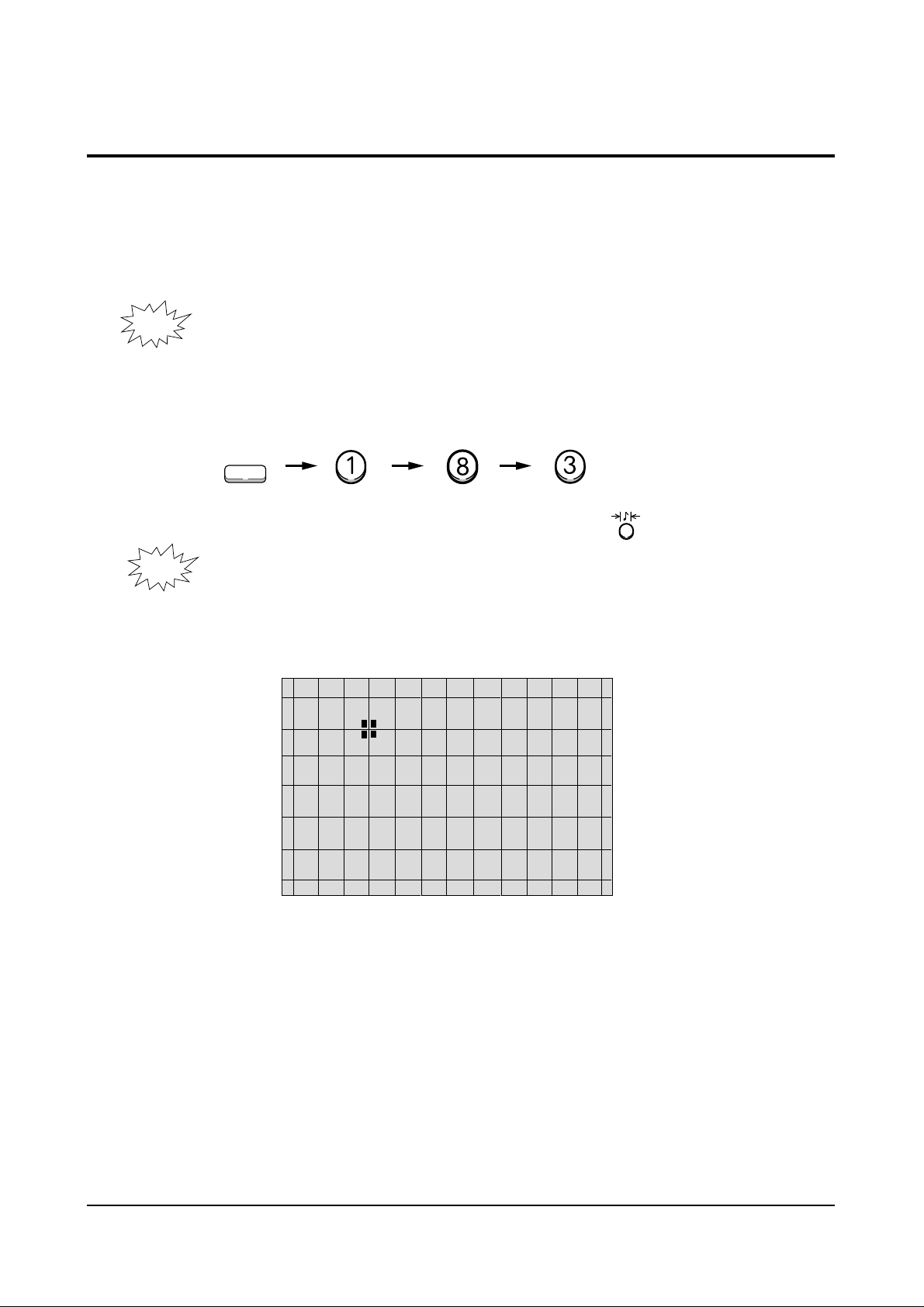
4-7 Convergence Adjustment
1. Warm up the TV for at least 30 minutes.
2. Input a PAL Signal. (Use an antenna or AV source.)
Make sure that both deflection and convergence yokes are
NOTE
3. Enter the Convergence Mode by pressing the remote control keys in the following sequence:
NOTE
properly adjusted so that the center of Green, Red, Blue pattern
is aligned on the center of screen jig.
R/B
S.STD
If OSD is displayed as shown in figure below, press the key to exit.
Then, redo step 3 to enter the Convergence Mode.
After entering the Convergence Mode, Stand by for about five seconds before
doing the adjustments.
Page 31

Alignment and Adjustments
4-20 Samsung Electronics
-/--
/
4. To adjust GREEN, first press the and the keys, and then press the key.
-/--
/
5. The key moves the cursor right, and the key moves the cursor left.
Page 32

Alignment and Adjustments
Samsung Electronics 4-21
The key moves the cursor horizontally or vertically.
MENU
MENU
MENU
NOTE
When the key is pressed once again, the cursor moves horizontally.
MENU
Page 33

Alignment and Adjustments
4-22 Samsung Electronics
7. Use the key for overall balance.
8. After the Line Shift is cancelled by pressing the key, use the Channel
and Volume keys (Up/Down) to make big adjustments.
9. After the green convergence adjustments are completed, press the key to
save the data.
Page 34

Alignment and Adjustments
Samsung Electronics 4-23
10. Superimpose the Red and Green colors by pressing the and
the keys.
11. To adjust RED, redo steps5~8.
Page 35

Alignment and Adjustments
4-24 Samsung Electronics
15. After the color adjustments are completed, press the ( ) key to save the data.
NOTE
to the left about five seconds later.
S.STD
16. After the Convergence Adjustments are completed, press the key to exit.
The cursor moves to center, and then automatically moves up and
Page 36

Alignment and Adjustments
Samsung Electronics 4-25
4-8 PC Mode
4-8-1 TV Setup Mode
Switch to External Mode
TV/External Key
SETUP MENU
TV SETUP
COMPUTER SETUP
PICTURE SETUP
EXIT
Select TV Setup
CH Down key
PC Enter
PC Enter
Switch to PC Mode
Select Key
TV SETUP MENU
H POS LEFT RIGHT
H SCALE SHRINK GROW
V POS DOWN UP
V SCALE SHRINK GROW
RECALL SETTINGS
EXIT
SAVE AND EXIT
Select TV Setup
Volume+ key
MAIN MENU
ZOOM
COMPRESS
FREEZE
SETUP
RESET
EXIT
Select menu
F.Menu Key
TV SETUP MENU
H P OS L EF T RI GHT
Adjust screen left to balance
Adjust horizontal position (left)
Volume- key
TV SETUP MENU
H SCALE SHR I
Adjust screen left to balance
Adjust horizontal position (right)
Volume - key
TV SETUP MENU
V SCAL E SHRIN K GROW
Adjust screen left to balance
Adjust horizontal position (bottom)
Volume+ key
N
K
GROW
TV SETUP MENU
H POS LEFT RIGHT
H SCALE SHRINK GROW
V POS DOWN UP
V SCALE SHRINK GROW
RECALL SETTINGS
EXIT
SAVE AND EXIT
Select vertical position adjustment
CH Down key
TV SETUP MENU
H POS LEFT RIGHT
H SCALE SHRINK GROW
V POS DOWN UP
V SCALE SHRINK GROW
RECALL SETTINGS
EXIT
SAVE AND EXI T
. Save and Exit
CH Down,Volume+ key
TV SETUP MENU
V POS DOWN UP
Adjust screen top to balance
Adjust vertical position (top)
Volume + key
SETUP MENU
TV SETUP
COMPUTER SETUP
PICTURE SETUP
EXIT
Exit
Page 37

Alignment and Adjustments
4-26 Samsung Electronics
4-8-2 Picture Setup Mode
1. Adjust four different modes:VGA3 (VGA), VGA (DOS), VESA (SVGA),
VEAS (XGA).
2). Perform the setup for each PC mode and picture setup.
SETUP MENU
TV SETUP
COMPUTER SETUP
PICTURE SETUP
EXIT
Select Picture Setup
CH Down key
PI CTURE SETUP MENU
BRIGHTNESS
COLOR SATURETION
FLICKER FILTER
VIDEO FILTER
RECALL SETTINGS
EXIT
SAVE AND EXIT
Select Picture Setup
Volume+ key
PICTURE SETUP MENU
BRI GHTNESS
Set in the bright screen
Adjust brightness
Volume+ key
PICTURE SETUP MENU
COL OR SATURATI ON
Set in the bright screen
Adjust color saturation
CH Down, Volume+ key
SETUP MENU
TV SETUP
COMPUTER SETUP
PI CTURE SETUP
EXIT
Finish picture setup
Volume+ key
PICTURE SETUP MENU
F L I CKER F I L TER
Set in the bright screen
Adjust flicker filter
CH Down, Volume+ key
MAIN MENU
ZOOM
COMPRESS
FREEZE
SETUP
RESET
EXIT
Finish Computer Setup
F.Menu key
PICTURE SETUP MENU
BRIGHTNESS
COLOR SATURETION
FLICKER FILTER
VIDEO FILTER
RECALL SETTINGS
EXIT
SAVE AND EXI T
Save and Exit
CH Down, Volume- key
PC
Exit
Page 38

Alignment and Adjustments
Samsung Electronics 4-27
4-8-3 Picture Setup Mode (computer setup mode only)
1. Adjust four different modes:VGA3 (VGA), VGA (DOS), VESA (SVGA),
VEAS (XGA).
2. Perform the setup for each PC mode and picture setup.
SETUP MENU
TV SETUP
COMPUTER SETUP
PICTURE SETUP
EXIT
Select Computer Setup
CH Down key
COMPUTER SETUP MENU
H SCALE SHRI NK GROW
Adjust screen left to balance
Adjust horizontal position (right)
Volume+ key
COMPUTER SETUP MENU
H P OS L EF T RI GHT
H SCALE SHRINK GROW
V POS DOWN UP
V SCALE SHRINK GROW
RECALL SETTINGS
EXIT
SAVE AND EXIT
Select Computer Setup
Volume+ key
COMPUTER SETUP MENU
H POS LEFT RIGHT
H SCALE SHRINK GROW
V POS DOWN UP
V SCALE SHRINK GROW
RECALL SETTINGS
EXIT
SAVE AND EXIT
Select vertical position adjustment
CH Down key
COMPUTER SETUP MENU
H P OS L EF T RI GHT
Adjust screen left to balance
Adjust horizontal position (left)
Volume- key
COMPUTER SETUP MENU
V POS DOWN UP
Adjust screen top to balance
Adjust vertical position (top)
Volume+ key
COMPUTER SETUP MENU
V SCAL E SHRIN K GROW
Adjust screen left to balance
Adjust horizontal position (bottom)
Volume+ key
COMPUTER SETUP MENU
H POS LEFT RIGHT
H SCALE SHRINK GROW
V POS DOWN UP
V SCALE SHRINK GROW
RECALL SETTINGS
EXIT
SAVE AND EXI T
Save and Exit
CH Down, Volume+ key
SETUP MENU
TV SETUP
COMPUTER SETUP
PICTURE SETUP
EXIT
Exit
Page 39

Alignment and Adjustments
4-28 Samsung Electronics
4-9 MICOM and Pins Voltage
4-9-1 Pin Layout
POW E
IR-IN
E
DVD- S
-
ED
L
STB
/
LNA -O N
LNA
PIP-MODE S/W
SCART1-IDENT
LOOP FILTER
ANALOG GND
SCART2-IDENT
ANALOG GND
ANALOG VCC
HALF TONE
OFF
-
PUT
IN
-
T
PI P-
N
PIP-L/L'
PROTECT
SCL2
SDA2
SUB-AFT
KEY1
MAIN-AFT
KEY2
OSD B
OSD G
OSD R
R
1
2
3
L
4
5
6
7
V
8
9
10
11
12
13
14
15
16
17
18
19
20
21
22
23
24
25
26
S
Z
M
8
0
4
C
1
S
Z
M
|
|
8
0
4
M
1
D2
52
POWER2
51
BUS-STOP
50
49
MAIN-NT-V
TTX-SCL
48
D3
47
TIMER-LED
46
SECAM L/L'
45
D1
44
AMP-MUTE
43
42
SOUND-RESET
MODE-S/W
41
40
XTAL GND
VCC
39
GND
38
XTAL2
37
XTAL1
36
/RESET
35
POWER-DTTV
34
DTTV-SCL
33
TTX-SDA
32
SCL1
31
SDA1
30
VSYNC
29
HSYNC
28
BLANK
27
Page 40

Alignment and Adjustments
Samsung Electronics 4-29
4-9-2 Micom Pins
1 POWER POWER ON/OFF RELAY CONTROL H--> L
2 IR IN REMOCON INPUT 4.7V
3 DVD-SEL DVD SELECTION OUTPUT 4.7V
4 STB-LED STAND-BY LED OUTPUT 4.6V
5 LNA-ON/OFF LNA CONTROL OUTPUT L
6 LNA-INPUT LNA INPUT L
7 PIP-NT-V PIP VIDEO SAW FILTER SWITCH L
8 PIP-L/L’ PIP SECAM SYSTEM SWITCH L
9 PROTECT PROTECT PORT L
10 PIP-MODE S/W PIP SECAM MODE SWITCH L
11 SCL 2 CLOCK BUS LINE 4.5V
12 SDA 2 DATA BUS LINE 4.5V
13 SCART1-IDENT SCART1 IDENT INPUT PORT L/H
14 LOOP FILTER LOOP FILTER L
15 ANALOG GND GND L
16 SUB-AFT SUB AUTO FINE TURNING CONTROL 2.3V
17 KEY 1 KEY SCAN 1 4.7V
18 MAIN-AFT MAIN TUNER AFT 2.3V
19 KEY 2 KEY SCAN 2 4.8V
20 SCART2-IDENT SCART2 IDENT INPUT PORT H
21 ANALOG GND GND L
22 ANALOG VCC VCC 5V
23 HALF TONE SIGNAL FOR OSC-FREQUENCY OSD CONTROL L
24 OSD B ON SCREEN DISPLAY BLUE OUTPUT L/H
25 OSD G ON SCREEN DISPLAY GREEN OUTPUT L/H
26 OSD R ON SCREEN DISPLAY RED OUTPUT L/H
PIN NO. ITEM FUNCTION OUT VOLT
Page 41

Alignment and Adjustments
4-30 Samsung Electronics
27 BLANK OSD BLAKING SIGNAL OUTPUT L/H
28 HSYNC HORIZONTAL SYNC INPUT 4.5V
29 VSYNC VERTICAL SYNC INPUT 4.6V
30 SDA1 DATA BUS LINE 4.5V
31 SCL1 CLOCK BUS LINE 4.5V
32 TTX-SDA TELETEXT DATA BUS LINE 5V
33 DTTV-SCL DTTV CLOCK LINE L
34 POWER-DTTV DTTV POWER CONTROL L
35 /RESET HARDWARE RESET 4.8V
36 XTAL1 CRYSTAL 1 2.3V
37 XTAL2 CRYSTAL 2 2.1V
38 GND GND L
39 VCC VCC 5V
40 XTAL GND CRYSTAL GND L
41 MODE-S/W MAIN SECAM MODE SWITCH 4.6V
42 SOUND-RESET SOUND IC RESET 4.9V
43 AMP-MUTE SOUND AMP. MUTE L
44 D1 CONV. MODE CONTROL DATA1 L/H
45 SECAM L/L’ MAIN SECAM SYSTEM SWITCH H
46 TIMER-LED TIMER LED 4.6V
47 D3 CONV. MODE CONTROL DATA3 L/H
48 TTX-SCL TELETEXT CLOCK BUS LINE 5V
49 MAIN-NT-V MAIN VIDEO SAW FILTER SWITCH L
50 BUS-STOP I
2
C BUS STOP 5V
51 POWER2 PC POWER CONTROL 4.6V
52 D2 CONV. MODE CONTROL DATA2 L/H
PIN NO. ITEM FUNCTION OUT VOLT
Page 42

Alignment and Adjustments
Samsung Electronics 4-31
4-9-3 PROSCAN MDL
1 DVD-Y DVD-Y INPUT 2.04V
2 GND GND GND
3 MAIN-Y/CVBS Y/CVBS INPUT 1.28V
4 MAIN-C C-INPUT 2.92V
5 GND GND GND
6 R/Pr R/Pr INPUT 2.0V
7 G/Y G/Y INPUT 2.0V
8 B/Pb B/Pb INPUT 2.0V
9 F/B FAST BLANK INPUT 0.16V
10 GND GND GND
11 HS1 1H-SYNC OUT 12 VS1 V-SYNC OUT 13 GND GND GND
14 SDA-2 SERIAL DATA LINE 2 3.0V
15 SCL-2 SERIAL CLOCK LINE 2 3.5V
16 5V-B 5V-B INPUT 5V
17 HD H-DRIVE OUT 1.6V
18 H-BLK H-BLANK INPUT 19 VD+ VERTICAL DRIVE (+VOLTAGE) 2.6V
20 VD- VERTICAL DRIVE (-VOLTAGE) 2.6V
21 ABL ABL INPUT 2.15V
22 V-BLK V-BLANK INPUT 23 EW EAST WEST OUT 2.5V
24 SC N.C 25 GND GND GND
26 SYNC V-SYNC OUT N.C
27 SYNC H-SYNC OUT N.C
28 5V-A 5V-B INPUT 29 GND GND GND
30 TEST-Y WHEN CG ADJ PATTERN INPUT -
PIN NO. ITEM FUNCTION OUT VOLT
Page 43

Alignment and Adjustments
4-32
Samsung Electronics
31 DTV-Y DTV-Y INPUT 32 DTV-Pb DTV-Pb INPUT 33 DTV-Pr DTV-Pr INPUT 34 - N.C 35 - N.C 36 GND GND GND
37 OSD-R OSD-R INPUT 38 OSD-G OSD-G INPUT 39 OSD-B OSD-B INPUT 40 YS BLANK(MICOM OUT) 41 YM NOT USED 42 V-MUTE VIDEO MUTE 4.72V
43 GND GND GND
44 9V 9V 9V
45 T/P-R TTX/PIP-R 46 T/P-G TTX/PIP-G 47 T/P-B TTX/PIP-B 48 T/P-F/B TTX/PIP-F/B 49 GND GND
50 R-OUT R-OUT 51 G-OUT G-OUT 52 B-OUT B-OUT 53 GND GND GND
54 IK IK OUT 3.65V
55 SPOT SPOT OUT 56 GND GND GND
57 VM-Y VM-Y OUT 5.42V
58 - N.C -
PIN NO. ITEM FUNCTION OUT VOLT
Page 44

Alignment and Adjustments
Samsung Electronics 4-33
4-9-4 PIP MODULE
1 SCL SERIAL CLOCK LINE 4.7V
2 SDA SERAL DATA LINE 4.7V
3 8V 8V INPIUT 8V
4 GND GND 0V
5 CVBS 5V-D INPUT 6 GND GND 0V
7 5V-D 5V-D INPUT 5V
8 GND GND 0V
9 PIP-AGC PIP-AGC OUTPUT 3.36V
10 PIP-MODE S/W PIP SECAM MODE SWITCH 0V
11 12V 12V INPUT 12V
12 PIP-L/L’ SECAM SYSTEM SWITCH 0V
13 PIP-NT-V PIP VIDEO SAW FILTER SWITCH 0V
14 SUB-AFT SUB-AFT OUTPUT 4.37V
15 GND GND 0V
16 IF-IN IF INPUT 17 IF-AGC N.C 18 V-SYNC V-SYNC INPUT 19 H-SYNC H-SYNC INPUT 20 F/B FAST BLANK OUTPUT 2.46V
21 GND GND 0V
22 B B OUTPUT 0.66V
23 G G OUTPUT 0.66V
24 R R OUTPUT 0.66V
PIN NO. ITEM FUNCTION OUT VOLT
Page 45

Alignment and Adjustments
4-34 Samsung Electronics
4-9-5 F/CONVERTER MODULE
1 5V 5V INPUT 5V
2 GND GND GND
3 R-IN PC R INPUT 4 G-IN PC G INPUT 5 B-IN PC B INPUT 6 GND GND GND
7 HS PC H-SYNC INPUT 8 VS PC V-SYNC INPUT 9 GND GND GND
10 SDA SERIAL DATA LINE 11 SCL SERIAL CLOCK LINE 12 GND GND GND
13 IR INPUT REMOCON 2.5V
14 GND GND GND
15 R-OUT/Y3 PC Y3 OUT 16 N.C N.C 17 B-OUT/C3 PC C3 OUT -
PIN NO. ITEM FUNCTION OUT VOLT
Page 46

Alignment and Adjustments
Samsung Electronics 4-35
4-9-6 SOUND MODULE
1 AV1-RIN SCART-R INPUT 2 AV1-LIN SCART-L INPUT 3 GND GND 0V
4 EXT-RIN EXT-R INPUT 5 EXT-LIN EXT-L INPUT 6 GND GND 0V
7 AV2-RIN AV2-R INPUT 8 AV2-LIN AV2-L INPUT 9 GND GND 0V
10 AV1-LOUT SCART1-L OUTPUT 11 AV1-ROUT SCART1-R OUTPUT 12 S-CONTROL0 EXT-SOUND CONTROL OUTPUT 0V/8V
13 S-CONTROL1 EXT-SOUND CONTROL OUTPUT 0V/8V
14 M-OUT-L MONITOR-L OUTPUT 15 M-OUT-R MONITOR-R OUTPUT 16 GND GND 0V
17 GND GND 0V
18 QSS-IN QUASI-SPLIT SOUND INPUT 1.95V
19 GND GND 0V
20 AM-IN AM INPUT 2.53V
21 SDA SERIAL DATA LINE 4.6V
22 SCL SERIAL CLOCK LINE 4.6V
23 GND GND 0V
24 5V-A 5V-A INPUT 5V
25 8V 8V-INPUT 8V
26 AV4-RIN AV4-R INPUT 27 AV4-LIN AV4-L INPUT 28 S-RESET SOUND RESET INPUT 5V
PIN NO. ITEM FUNCTION OUT VOLT
Page 47

Alignment and Adjustments
4-36 Samsung Electronics
30 12V 12V INPUT 12V
31 GND GND 0V
32 SURROUND DOLBY SURROUND OUTPUT 5.6V
33 GND GND 0V
34 CENTER DOLBY CENTER OUTPUT 5.6V
35 GND GND 0V
36 MAIN-R MAIN-R OUTPUT 5.6V
37 MAIN-L MAIN-L OUTPUT 5.6V
38 GND GND 0V
39 NC N.C 40 NC N.C -
PIN NO. ITEM FUNCTION OUT VOLT
Page 48

Alignment and Adjustments
Samsung Electronics 4-37
4-9-7 H/V MODULE
1 12V 12V INPUT 12V
2 GND GND GND
3 HD H-DRIVE INPUT 1.6V
4 V-BLK V-BLANK INPUT 0.72V
5 2H-BLK 2H-BLANK OUT 0.54V
6 GND GND GND
7 PROTECT PROTECT ACTIV H
8 FBT-DC FBT DC FEED BACK 4.87V
9 X-RAY X-RAY PROTECT F/B 2.10V
10 N.C N.C 11 HV-REG HV-REG 3.54V
12 HV-DRIVE HIGH VOLTAGE DRIVE 0.32V
13 H-DRIVE H-DRIVE OUT 25V
14 GND GND GND
15 HEATER HEATER INPUT AC[0.7V]
16 N.C N.C 17 208V 208V INPUT 208V
18 N.C N.C 19 GND GND GND
20 V2 V2 INPUT
21 N.C N.C 22 N.C N.C 23 D-FOCUS DYNAMIC FOCUS OUT 24 N.C N.C 25 N.C N.C 26 SCREEN SCREEN INPUT 1356V
PIN NO. ITEM FUNCTION OUT VOLT
Page 49

Alignment and Adjustments
4-38 Samsung Electronics
4-9-8 CONV- MODULE
1 SDA D2 2 SCL D1 3 GND GND GND
4 BV BLUE VERTICAL OUT 5 BH BLUE HORIZONTAL OUT 6 GV GREEN VERTICAL OUT 7 GH GREEN HORIZONTAL OUT 8 RV RED VERTICAL OUT 9 RH RED HORIZONTAL OUT 10 -5.4V -5.4V INPUT -5.4V
11 5.4V 5.4V INPUT +5.4V
12 V-BLK V-BLK INPUT 13 GND GND GND
14 H-BLK H-BLK INPUT 0.52V
15 COMP COMP VIDEO OUTPUT (N.C) N.C
16 IR INPUT REMOCON 3V
17 CTRL CTRL (N.C) N.C
18 D3/SEL D3 0.2V
19 B WHEN TEST PATTERN B OUT 20 G(TEST) WHEN TEST PATTERN G OUT 21 R WHEN TEST PATTERN R OUT 22 SYNC SYNC OUTPUT 4.41V
PIN NO. ITEM FUNCTION OUT VOLT
Page 50

Alignment and Adjustments
Samsung Electronics 4-39
4-9-9 TTX-MODULE
1 H-SYNC HOR. SYNC INPUT 3.6V
2 V-SYNC VER. SYNC INPUT 3.6V
3 NC N.C 4 GND GND GND
5 F/B-OUT FAST BLANK OUT 0V/1.4V
6 B-OUT B OUTPUT 1.8V/2.4V
7 G-OUT G OUTPUT 1.8V/2.4V
8 R-OUT R OUTPUT 1.8V/2.4V
9 GND GND GND
10 5V-D 5V-D INPUT 5V
11 GND GND GND
12 12V 12V INPUT 12V
13 GND GND GND
14 F/B-IN EXT. FATS BLANK INPUT 15 B-IN EXT. B-INPUT 0.6V
16 G-IN EXT. G-INPUT 0.6V
17 R-IN EXT. R-INPUT 0.6V
18 GND GND GND
19 CVBS-IN CVBS INPUT 1.1V
20 SCL SERAL CLOCK LINE 5V
21 SDA SERIAL DATA LINE 5V
PIN NO. ITEM FUNCTION OUT VOLT
Page 51

Troubleshooting
Samsung Electronics 5-1
5. Troubleshooting
5-1 Convergence Misaligned
Normal
Check the
output voltage and waveform
of CN802, CN203 on
the Convergence Board
Abnormal
Check HZ01 out pin
(BV, BH, RV, RH, GV, GH)
Normal
Check the associated
circuitry
Abnormal
Check Convergence
Module
1. Check F802, F855,
F805, F806 on
the SUB Board
2. Check the output
from H-BLK, V-BLK,
D1, D2, D3 on
the Main Board
Page 52

5-2 No Sound
Troubleshooting
5-2 Samsung Electronics
Check if CN601 is inserted
Normal
Check IC665
output pins 2,4
Abnormal
Check IC665 input pin 3
Normal
Check IC665
mute pin 5
Normal
Check IC665
output pins 7,11
Abnormal
Insert CN601
(Connector)
Normal
Check Speaker
Abnormal
Check F854 on
the SUB Board
Abnormal
Check the mute circuit
Normal
Abnormal
Check IC601
input pins 35, 38
Abnormal
Check H006
input pins 15,17
Abnormal
Check ICV01
Input pins 49,51
Abnormal
Check H003
out Pins 1,2
Check IC665
Normal
Check Tone Control
Normal
Check the 3D Phonic
circuit
Normal
Check ICV01
Page 53

Troubleshooting
Samsung Electronics 5-3
5-3 No Raster (Sound OK)
Normal
Check High Voltage
Normal
Check CN501
pins 1,3,5
Normal
Check CN501
(Connector)
Abnormal
Check H007
input pins 3,4
Check Heater
Normal
Check IC501, 531,561
Abnormal
Check CN501
(Connector)
Normal
Abnormal
Check CRT PCB pin 1
Normal
Check H401 CN402
HV-REG
Abnormal
Check H401,
IC471
Abnormal
Check H401
Abnormal
Check H401 R437A
Normal
Check CN402 input
pin 12 (HV-DRIVER)
Normal
Check H401
(OUT BLOCK)
Abnormal
Check ICV01 input
pin 48
Abnormal
Check H009
input pin 1
Abnormal
Check ICV01
input pin 50
Abnormal
Check H004
Check H007
Normal
Check ICV01
Normal
Check H009
Normal
Check ICV01
Page 54

Exploded View & Parts List
Samsung Electronics 6-1
No Code No Description Specification Q’ty Remark
1 AA91-00498A ASSY CABINET MASK;-,HB,GRAY,G906+D902 DO P51A 1
2 AA60-00069E SPACER-SCREEN;43,53,61J8,ABS,-,-,-,BLK,-,-,HB 2
3 AA60-00069D SPACER-SCREEN;43,53,61J8,ABS,-,-,-,BLK,-,-,HB 2
4 AA67-00030A SUN-SCREEN;-,43NEW,H/C,A/S,PMMA,T=93%,T2.0,910*692 1
5 AA67-00028A SCREEN-TINT;-,43NEW,-,PMMA,TINT=10%,T3.0,910*692,- 1
6 0203-001279 TAPE-OPP MASKING;#232,T0.14,W15,L50000,YEL 4(M)
7 AA91-00497G ASSY-FRONT,BOT;-,VO G4309,HIPS,SVP-43J8SR 1
8 AA91-00476D ASSY-CONTROL;-,HB BLK,ABS DO,SVP-54J8SR 1
9 AA95-00863A ASSY-PCB,A/V FRONT;-,SVP-54J8SR,P51A,-,-,- 1
10 AA64-01392C DOOR-AV;43,54,62J8,ABS,HB,GRAY,-,-,LG807 1
11 AA91-00496B ASSY-WOOD,BOT;-,-,WOOD,SVP-43J8SR,J7 1
12 AA64-01385B CABINET-BACK,SIDE;43,54,62J8,-,HIPS,HB,BLK 2
13 AA91-00495A ASSY-WOOD,TOP;-,-,WOOD,SVP-43J8SR,J7 1
14 6006-001094 SCREW-ASS’Y WOOD;WW,HH,+,M7,L32,ZPC(YEL),SWRCH18A 6
15 AA91-00489B ASSY-BRKT,MIRROR;-,-,SECC-1 T1.0,54J8 3
16 AA63-60131F SPACER-FELT;PCJ612R,FELT,-,-,-,BLK,T0.5,-,280X50 2
17 AA67-00079A MIRROR-BACK;43J8,GLASS,812*580*544(35)*3,-,-,T3.0, 1
18 AA64-01378B CABINET-BACK,TOP;43J8,-,HIPS,HB,BLK 1
19 AA95-00692A ASSY-PCB,CONV AMP -,SVP-53J5DR,P51A,-,-,20 AA95-00691B ASSY-PCB,SUB;-,SVP-53J5DR,P51A,-,-,- 1
21 AA95-00695B ASSY-PCB,TERMINAL;-,SVP-53J5DR,P51A,-,-,- 1
22 AA94-02602G ASSY PCB MAIN(OPT);SVP-43J8SR,P51A,KOREA,- 1
23 AA61-00504B HOLDER-CHASSIS;43,54,62J8,ABS,GRAY,VO,-,- 1
24 AA64-01384B CABINET-BACK,BOT;43,54,62J8,-,HIPS,VO,BLK 1
25 AA64-01395B INLAY-TERMINAL;43,54,62J8,PS SHEET,T0.5,-,BLK,-,- 1
26 AA60-00072A SPACER-COVER,DUST;43,53,61J8,FELT, 1
27 AA94-02868A ASSY CRT-(R);P16LSG03RJA,+380MG,7,BARE,SVP-43J8SR 1
28 AA94-02870B ASSY CRT-(G);P16LSG03HKA,+380MG,7,BARE,SVP-43J8SR 1
29 AA94-02869A ASSY CRT-(B);P16LSG03BMB,+380MG,7,BARE,SVP-43J8SR 1
30 AA26-30006E TRANS-FLYBACK;-,FWZ-50A001B(S),50KV 1
31 6006-001094 SCREW-ASS’Y WOOD;WW,HH,+,M7,L32,ZPC(YEL),SWRCH18A 4
32 AA61-00475B BRACKET-CRT,MAIN;54,SECC,T1.6,-,- 1
33 AA59-00171A MODULE-FOCUS,PACK;SVP-5200,S300-P3, 1
6. Exploded View & Parts List
6-1 SP43J8
Page 55

Exploded View & Parts List
6-2 Samsung Electronics
No Code No DescriptionSpecification Q’ty Remark
1 AA91-00478B ASSY CABINET MASK;-,HB,GRAY,G906+D902 DO P53A 1
2 AA60-00069C SPACER-SCREEN;ABS,-,-,-,BLK,-,-,HB 2
3 AA60-00069B SPACER-SCREEN;ABS,-,-,-,BLK,-,-,HB 2
4 AA67-00103A SUN SCREEN;53,-,T2.0,1125*853,-,-,AR,HC,AS 1
5 AA67-00027A SCREEN-TINT;-,53,-,PMMA,TINT=10%,T3.0,1125*854,- 1
6 0203-001279 TAPE-OPP MASKING;#232,T0.14,W15,L50000,YEL 4(M)
7 AA91-00477G ASSY-FRONT,BOT;-,VO G4309,HIPS,SVP-54J8SR 1
8 AA91-00476D ASSY-CONTROL;-,HB BLK,ABS DO,SVP-54J8SR 1
9 AA95-00863B ASSY-PCB,A/V FRONT;-,SVP-54J8M,P53A,-,-,- 1
10 AA64-01392C DOOR-AV;43,54,62J8,ABS,HB,GRAY,-,-,LG807 1
11 AA91-00475B ASSY-WOOD,BOT;-,-,WOOD,SVP-54J8SR,54J7 1
12 AA64-01385B CABINET-BACK,SIDE;43,54,62J8,-,HIPS,HB,BLK 2
13 AA91-00474A ASSY-WOOD,TOP;-,-,WOOD,SVP-54J8SR,54J7 1
14 6006-001094 SCREW-ASS’Y WOOD;WW,HH,+,M7,L32,ZPC(YEL),SWRCH18A 8
15 AA91-00489B ASSY-BRKT,MIRROR;-,-,SECC-1 T1.0,54J8 4
16 AA63-60131F SPACER-FELT;,FELT,-,-,-,BLK,T0.5,-,280X50 2
17 AA67-00080A MIRROR-BACK;54J8,GLASS,940*686*673(132)*3,-,-,T3.0 1
18 AA64-01379B CABINET-BACK,TOP;54J8,-,HIPS,HB,BLK 1
19 AA95-00448C ASSY-PCB,CONV.AMP;-,SVP-53J5M,P53A,-,-,- 1
20 AA95-00447B ASSY-PCB,SUB;-,SVP-53J5M,P53A,-,-,- 1
21 AA95-00444D ASSY-PCB,TERMINAL;-,SVP-53J5M,P53A,-,-,KOREA 1
22 AA94-01686L ASSY PCB MAIN(OPT) SVP-54J8M,P53A,KOREA,23 AA61-00504B HOLDER-CHASSIS;43,54,62J8,ABS,GRAY,VO,-,- 1
24 AA64-01384B CABINET-BACK,BOT;43,54,62J8,-,HIPS,VO,BLK 1
25 AA64-01395C INLAY-TERMINAL;43,54,62J8,PS SHEET,T0.5,-,BLK,-,P5 1
26 AA60-00072A SPACER-COVER,DUST;43,53,61J8,FELT, 1
27 AA94-03134A ASSY CRT-(R) P16LSG03RJA,+380MG,7,BARE,SVP-54J8M,28 AA94-03136A ASSY CRT-(G) P16LSG03HKA,+380MG,7,BARE,SVP-54J8M,29 AA94-03135A ASSY CRT-(B) P16LSG03BMB,+380MG,7,BARE,SVP-54J8M,30 AA26-30006E TRANS-FLYBACK;-,FWZ-50A001B(S),50KV 1
31 6006-001094 SCREW-ASS’Y WOOD;WW,HH,+,M7,L32,ZPC(YEL),SWRCH18A 4
32 AA61-00475B BRACKET-CRT,MAIN;54,SECC,T1.6,-,- 1
33 AA59-00171A MODULE-FOCUS,PACK;SVP-5200,S300-P3, 1
6-2 SP54J8
Page 56

Electrical Parts List
Samsung Electronics 7-1
ASSY PCB MAIN(OPT)
1 * AA94-03459H ASSY PCB MAIN(OPT);SP43J8HFX/SAP,J51A,SI
..2 C664 2401-001068 C-AL;3300uF,20%,50V,GP,BK,22x40,10
..2 C665 2401-000737 C-AL;2200uF,20%,50V,GP,TP,18x35.5,7
..2 CN801 3711-003974 CONNECTOR-HEADER;BOX,12P ,1R,2.5mm,STRAIG
..2 CNT01 3710-001208 CONNECTOR-SOCKET;32P,2R,2.54mm,STRAIGHT,
..2 CNT02 3710-001208 CONNECTOR-SOCKET;32P,2R,2.54mm,STRAIGHT,
..2 CS803 2401-003370 C-AL;47uF,20%,450V,GP,BK,16X35.5,7.
..2 H001 AA40-10006S TUNER-F/S;TECC2949PG30A(S),PAL-B/G,TR,18
..2 IC101 AA96-00110C ASSY-H/S;-,-,AA62-30013K,SI-3090C,...3 1203-000577 IC-VOLTAGE REGUATOR;3090,ZIP,5P,-,PLASTI
...3 6003-000333 SCREW-TAPTITE;RH,+,2S,M3,L10,ZPC(YEL),SW
...3 AA62-30013K HEATSINK-ES;-,-,-,-,44/18,-,WHT,A6063 EX
..2 IC102 AA96-00110A ASSY-H/S;-,-,AA62-30013K,SI-3050C,...3 1203-000203 IC-POSI.ADJUST REG.;3050,TO-220,5P,-,PLA
...3 6003-000333 SCREW-TAPTITE;RH,+,2S,M3,L10,ZPC(YEL),SW
...3 AA62-30013K HEATSINK-ES;-,-,-,-,44/18,-,WHT,A6063 EX
..2 IC103 1204-001276 IC-SOUND PROCESSOR;TDA9810,DIP,24P,400MI
..2 IC502 AA96-00110A ASSY-H/S;-,-,AA62-30013K,SI-3050C,..2 IC503 AA96-00110A ASSY-H/S;-,-,AA62-30013K,SI-3050C,..2 IC504 AA96-00110A ASSY-H/S;-,-,AA62-30013K,SI-3050C,..2 IC665 AA96-00038A ASSY-H/S;-,SOUND AMP,AA62-30173E,TDA726
...3 0205-000129 GREASE-SILICON;SC102,JAPAN S.N.A
...3 1201-001026 IC-POWER AMP;7265,ZIP,11P,19.6MIL,DUAL,1
...3 6003-000333 SCREW-TAPTITE;RH,+,2S,M3,L10,ZPC(YEL),SW
...3 AA62-30173E HEAT -SINK,ES;-,-,T1.0,WHITE,SCREW -HOLE(1 S.N.A
..2 IF/CAB AA39-30007B IF-CABLE;-,T,150mm,1365#26
..2 L201 AA27-10001C COIL-CHOKE;-,100uH,K,-,5.0A,ST,700UH-K(R
..2 L603 AA29-00004A FILTER-LINE NOISE;-,20UH,3A,AC80-260V,TQ
..2 QZ107 AA96-50162F ASSY-H/S;-,POWER,AA62-30013E,2SA1011,30
...3 0502-000131 TR-POWER;2SA1011-D,PNP,1.2W,TO-220,-,60
...3 6003-000333 SCREW-TAPTITE;RH,+,2S,M3,L10,ZPC(YEL),SW
...3 AA62-30013E HEAT-SINK,ES;-,A6063 EXTR,-,-,30(21) T02
..2 QZ108 AA96-50162G ASSY -H/S;-,AMP,AA62-30013E,2SC2344,30MM
...3 0502-000153 TR-POWER;2SC2344-D,NPN,1.2W,TO-220,-,60
...3 6003-000333 SCREW-TAPTITE;RH,+,2S,M3,L10,ZPC(YEL),SW
...3 AA62-30013E HEAT-SINK,ES;-,A6063 EXTR,-,-,30(21) T02
..2 R913 2001-000786 R-CARBON;47KOHM,5%,1/8W,AA,TP,1.8X3.2MM
..2 RL801 3501-001053 RELAY -POWER;5Vdc,530mW,10A,1FormA,15mS,5
..2 TS801 AA26-00019A TRANS-SWITCHING;-,AC80~260V ,-,US,-,4MH,B
..2 X901 2801-003224 CRYSTAL-UNIT;32.768KHZ,20PPM,28-AAY,12.5
..2 AA95-00427B ASSY SOUND;-,SP43J5P3S/XTT,J51A,AA95-004
...3 C614 2401-000962 C-AL;22uF,20%,50V,GP,TP,5x11,5
...3 C615 2203-000595 C-CERAMIC,CHIP;0.22nF ,5%,50V,NP0,TP,2012
...3 C616 2203-000938 C-CERAMIC,CHIP;0.47nF ,5%,50V,NP0,TP,2012
...3 C617 2203-000142 C-CERAMIC,CHIP;1.5nF ,10%,50V,X7R,TP,2012
...3 C618 2203-000444 C-CERAMIC,CHIP;1nF ,10%,50V,X7R,TP,2012,...3 C619 2203-000444 C-CERAMIC,CHIP;1nF ,10%,50V,X7R,TP,2012,...3 C620 2401-000660 C-AL;2.2uF,20%,50V,GP,TP,5x11,5
...3 C621 2401-000660 C-AL;2.2uF,20%,50V,GP,TP,5x11,5
...3 C622 2203-000701 C-CERAMIC,CHIP;0.002nF ,0.25pF,50V,NP0,TP
...3 C623 2203-000701 C-CERAMIC,CHIP;0.002nF ,0.25pF,50V,NP0,TP
...3 C624 2203-001077 C-CERAMIC,CHIP;0.056nF ,5%,50V,NP0,TP,201
...3 C625 2203-001077 C-CERAMIC,CHIP;0.056nF ,5%,50V,NP0,TP,201
...3 C626 2401-000962 C-AL;22uF,20%,50V,GP,TP,5x11,5
...3 C627 2203-000938 C-CERAMIC,CHIP;0.47nF ,5%,50V,NP0,TP,2012
...3 C628 2203-000142 C-CERAMIC,CHIP;1.5nF ,10%,50V,X7R,TP,2012
...3 C629 2203-001077 C-CERAMIC,CHIP;0.056nF ,5%,50V,NP0,TP,201
...3 C630 2401-000480 C-AL;10uF,20%,50V,GP,TP,5x11,5
...3 C631 2203-000181 C-CERAMIC,CHIP;100nF ,+80-20%,25V,Y5V,TP,
...3 C632 2401-002229 C-AL;470nF,20%,50V,WT,TP,5x11,5
...3 C633 2401-002229 C-AL;470nF,20%,50V,WT,TP,5x11,5
...3 C634 2203-000784 C-CERAMIC,CHIP;0.33nF ,5%,50V,NP0,TP,2012
...3 C635 2203-000784 C-CERAMIC,CHIP;0.33nF ,5%,50V,NP0,TP,2012
...3 C636 2203-000181 C-CERAMIC,CHIP;100nF ,+80-20%,25V,Y5V,TP,
...3 C637 2401-000027 C-AL;4.7uF,20%,50V,GP,TP,5x11,5
...3 C638 2401-002235 C-AL;10uF,20%,16V,GP,TP,5x11mm,5mm
...3 C639 2401-002235 C-AL;10uF,20%,16V,GP,TP,5x11mm,5mm
...3 C640 2203-000938 C-CERAMIC,CHIP;0.47nF ,5%,50V,NP0,TP,2012
...3 C641 2203-000142 C-CERAMIC,CHIP;1.5nF ,10%,50V,X7R,TP,2012
...3 C642 2401-000480 C-AL;10uF,20%,50V,GP,TP,5x11,5
...3 C643 2401-000027 C-AL;4.7uF,20%,50V,GP,TP,5x11,5
...3 C644 2401-000027 C-AL;4.7uF,20%,50V,GP,TP,5x11,5
...3 C645 2401-000027 C-AL;4.7uF,20%,50V,GP,TP,5x11,5
...3 C646 2401-000027 C-AL;4.7uF,20%,50V,GP,TP,5x11,5
...3 C649 2401-002300 C-AL;47uF,20%,50V,GP,TP,6.3x11,5
...3 C650 2203-000979 C-CERAMIC,CHIP;47nF ,10%,50V,X7R,TP,2012
...3 C651 2401-000365 C-AL;100uF,20%,50V,WT,TP,10x12.5mm,
...3 C653 2203-000784 C-CERAMIC,CHIP;0.33nF ,5%,50V,NP0,TP,2012
...3 C654 2401-002229 C-AL;470nF,20%,50V,WT,TP,5x11,5
...3 C655 2203-000784 C-CERAMIC,CHIP;0.33nF ,5%,50V,NP0,TP,2012
...3 C656 2401-002229 C-AL;470nF,20%,50V,WT,TP,5x11,5
...3 C657 2401-002229 C-AL;470nF,20%,50V,WT,TP,5x11,5
...3 C658 2203-000784 C-CERAMIC,CHIP;0.33nF ,5%,50V,NP0,TP,2012
...3 C661 2203-000784 C-CERAMIC,CHIP;0.33nF ,5%,50V,NP0,TP,2012
...3 C662 2401-002229 C-AL;470nF,20%,50V,WT,TP,5x11,5
...3 C663 2401-002229 C-AL;470nF,20%,50V,WT,TP,5x11,5
...3 C664 2203-000784 C-CERAMIC,CHIP;0.33nF ,5%,50V,NP0,TP,2012
...3 C667 2203-000784 C-CERAMIC,CHIP;0.33nF ,5%,50V,NP0,TP,2012
...3 C668 2401-002229 C-AL;470nF,20%,50V,WT,TP,5x11,5
...3 C669 2401-002229 C-AL;470nF,20%,50V,WT,TP,5x11,5
...3 C670 2203-000784 C-CERAMIC,CHIP;0.33nF ,5%,50V,NP0,TP,2012
...3 C684 2401-000480 C-AL;10uF,20%,50V,GP,TP,5x11,5
...3 C688 2401-000962 C-AL;22uF,20%,50V,GP,TP,5x11,5
...3 C691 2401-000962 C-AL;22uF,20%,50V,GP,TP,5x11,5
...3 C692 2203-000260 C-CERAMIC,CHIP;10nF ,10%,50V,X7R,TP,2012
...3 C695 2203-000761 C-CERAMIC,CHIP;330nF ,10%,16V,X7R,TP,2012
...3 C696 2203-000170 C-CERAMIC,CHIP;1.8nF ,10%,50V,X7R,TP,2012
...3 C697 2203-000170 C-CERAMIC,CHIP;1.8nF ,10%,50V,X7R,TP,2012
...3 CB1 2401-000365 C-AL;100uF ,20%,50V,WT,TP,10x12.5mm,
...3 CD601 2203-000260 C-CERAMIC,CHIP;10nF,10%,50V,X7R,TP,2012
...3 CD602 2203-000142 C-CERAMIC,CHIP;1.5nF,10%,50V,X7R,TP,2012
...3 CD603 2401-000962 C-AL;22uF,20%,50V,GP,TP,5x11,5
...3 CD604 2203-000595 C-CERAMIC,CHIP;0.22nF,5%,50V,NP0,TP,2012
...3 CD605 2203-000938 C-CERAMIC,CHIP;0.47nF,5%,50V,NP0,TP,2012
...3 CD606 2401-000962 C-AL;22uF,20%,50V,GP,TP,5x11,5
...3 CD607 2203-000938 C-CERAMIC,CHIP;0.47nF,5%,50V,NP0,TP,2012
...3 CD608 2203-000142 C-CERAMIC,CHIP;1.5nF,10%,50V,X7R,TP,2012
...3 CD609 2203-000181 C-CERAMIC,CHIP;100nF,+80-20%,25V,Y5V,TP,
...3 CD610 2401-000480 C-AL;10uF,20%,50V,GP,TP,5x11,5
...3 CD611 2203-000181 C-CERAMIC,CHIP;100nF,+80-20%,25V,Y5V,TP,
...3 CD612 2401-000027 C-AL;4.7uF,20%,50V,GP,TP,5x11,5
...3 CD613 2401-000660 C-AL;2.2uF,20%,50V,GP,TP,5x11,5
...3 CD615 2401-000660 C-AL;2.2uF,20%,50V,GP,TP,5x11,5
...3 CD616 2203-000444 C-CERAMIC,CHIP;1nF,10%,50V,X7R,TP,2012,...3 CD618 2203-000444 C-CERAMIC,CHIP;1nF,10%,50V,X7R,TP,2012,...3 CD619 2401-002235 C-AL;10uF,20%,16V,GP,TP,5x11mm,5mm
...3 CD620 2401-002235 C-AL;10uF,20%,16V,GP,TP,5x11mm,5mm
...3 CD621 2203-000938 C-CERAMIC,CHIP;0.47nF,5%,50V,NP0,TP,2012
...3 CD622 2203-000142 C-CERAMIC,CHIP;1.5nF,10%,50V,X7R,TP,2012
...3 CD623 2401-000480 C-AL;10uF,20%,50V,GP,TP,5x11,5
...3 CD624 2203-000495 C-CERAMIC,CHIP;2.2nF,10%,50V,X7R,TP,2012
...3 CD625 2401-000962 C-AL;22uF,20%,50V,GP,TP,5x11,5
...3 CD626 2203-000495 C-CERAMIC,CHIP;2.2nF,10%,50V,X7R,TP,2012
...3 CD627 2401-000962 C-AL;22uF,20%,50V,GP,TP,5x11,5
...3 CD628 2203-000260 C-CERAMIC,CHIP;10nF,10%,50V,X7R,TP,2012
...3 CD629 2401-000365 C-AL;100uF,20%,50V,WT,TP,10x12.5mm,
...3 CD630 2203-000761 C-CERAMIC,CHIP;330nF,10%,16V,X7R,TP,2012
...3 CDB1 2401-000365 C-AL;100uF ,20%,50V,WT,TP,10x12.5mm,
...3 CN601A 3711-003626 CONNECTOR-HEADER;NOWALL,20P,1R,2.5mm,ANG
...3 CN602A 3711-003626 CONNECTOR-HEADER;NOWALL,20P,1R,2.5mm,ANG
...3 IC601 1204-001689 IC-SOUND PROCESSOR;MSP3410D-C5,PLCC,68P,
...3 IC604 1201-000541 IC-OP AMP;062,SOP,8P,153MIL,DUAL,6V/mV,P
7-1 SP43J8HFX/SAP
Level Loc. No. Code No. Description ; Specification Remark Level Loc. No. Code No. Description ; Specification Remark
7. Electrical Parts List
Page 57

...3 ICD601 1204-001198 IC-DECODER;DPL3519A-A2,PLCC,68P ,-,PLASTI
...3 ICD602 1201-000541 IC-OP AMP;062,SOP,8P,153MIL,DUAL,6V/mV,P
...3 L601 2701-000170 INDUCTOR-AXIAL;3.9uH,10%,3x7mm
...3 L602 2701-000170 INDUCTOR-AXIAL;3.9uH,10%,3x7mm
...3 L603 2701-000112 INDUCTOR-AXIAL;100uH,10%,3x7mm
...3 LD601 2701-000170 INDUCTOR-AXIAL;3.9uH,10%,3x7mm
...3 LD602 2701-000112 INDUCTOR-AXIAL;100uH,10%,3x7mm
...3 LD603 2701-000170 INDUCTOR-AXIAL;3.9uH,10%,3x7mm
...3 PCB AA41-00087A PCB-AUDIO;PLT51A,2L,FR-4,180X245X1.6T ,3A S.N.A
...3 Q606 0501-000727 TR-SMALL SIGNAL;BC848C,NPN,310mW,SOT-23,
...3 Q607 0501-000727 TR-SMALL SIGNAL;BC848C,NPN,310mW,SOT-23,
...3 R601 2007-000029 R-CHIP;0OHM,5%,1/10W,DA,TP,2012
...3 R602 2007-000029 R-CHIP;0OHM,5%,1/10W,DA,TP,2012
...3 R610 2007-000290 R-CHIP;100OHM,5%,1/10W,DA,TP,2012
...3 R611 2007-000290 R-CHIP;100OHM,5%,1/10W,DA,TP,2012
...3 R614 2007-000468 R-CHIP;1KOHM,5%,1/10W,DA,TP,2012
...3 R617 2007-000931 R-CHIP;470OHM,5%,1/10W,DA,TP,2012
...3 R618 2007-000931 R-CHIP;470OHM,5%,1/10W,DA,TP,2012
...3 R619 2007-000290 R-CHIP;100OHM,5%,1/10W,DA,TP,2012
...3 R620 2007-000290 R-CHIP;100OHM,5%,1/10W,DA,TP,2012
...3 R621 2007-000290 R-CHIP;100OHM,5%,1/10W,DA,TP,2012
...3 R622 2007-000290 R-CHIP;100OHM,5%,1/10W,DA,TP,2012
...3 R623 2007-000477 R-CHIP;1MOHM,5%,1/10W,DA,TP,2012
...3 R624 2007-000477 R-CHIP;1MOHM,5%,1/10W,DA,TP,2012
...3 R625 2007-000477 R-CHIP;1MOHM,5%,1/10W,DA,TP,2012
...3 R626 2007-000477 R-CHIP;1MOHM,5%,1/10W,DA,TP,2012
...3 R632 2007-000931 R-CHIP;470OHM,5%,1/10W,DA,TP,2012
...3 R633 2007-000931 R-CHIP;470OHM,5%,1/10W,DA,TP,2012
...3 R634 2007-000931 R-CHIP;470OHM,5%,1/10W,DA,TP,2012
...3 R635 2007-000931 R-CHIP;470OHM,5%,1/10W,DA,TP,2012
...3 R636 2007-000931 R-CHIP;470OHM,5%,1/10W,DA,TP,2012
...3 R637 2007-000931 R-CHIP;470OHM,5%,1/10W,DA,TP,2012
...3 R638 2007-000931 R-CHIP;470OHM,5%,1/10W,DA,TP,2012
...3 R660 2007-000872 R-CHIP;4.7KOHM,5%,1/10W,DA,TP,2012
...3 R661 2007-000872 R-CHIP;4.7KOHM,5%,1/10W,DA,TP,2012
...3 R664 2007-001177 R-CHIP;8.2KOHM,5%,1/10W,DA,TP,2012
...3 R665 2007-000774 R-CHIP;33KOHM,5%,1/10W,DA,TP,2012
...3 R666 2007-000872 R-CHIP;4.7KOHM,5%,1/10W,DA,TP,2012
...3 R669 2007-001177 R-CHIP;8.2KOHM,5%,1/10W,DA,TP,2012
...3 R670 2007-000774 R-CHIP;33KOHM,5%,1/10W,DA,TP,2012
...3 R672 2007-000586 R-CHIP;22KOHM,5%,1/10W,DA,TP,2012
...3 R673 2007-000586 R-CHIP;22KOHM,5%,1/10W,DA,TP,2012
...3 R674 2007-000300 R-CHIP;10KOHM,5%,1/10W,DA,TP,2012
...3 R675 2007-000300 R-CHIP;10KOHM,5%,1/10W,DA,TP,2012
...3 RB1 2007-000941 R-CHIP;47KOHM,5%,1/10W,DA,TP,2012
...3 RB2 2007-000941 R-CHIP;47KOHM,5%,1/10W,DA,TP,2012
...3 RB3 2007-000328 R-CHIP;11KOHM,5%,1/10W,DA,TP,2012
...3 RB4 2007-000328 R-CHIP;11KOHM,5%,1/10W,DA,TP,2012
...3 RD601 2007-000468 R-CHIP;1KOHM,5%,1/10W,DA,TP,2012
...3 RD602 2007-000872 R-CHIP;4.7KOHM,5%,1/10W,DA,TP,2012
...3 RD604 2007-001177 R-CHIP;8.2KOHM,5%,1/10W,DA,TP,2012
...3 RD605 2007-000774 R-CHIP;33KOHM,5%,1/10W,DA,TP,2012
...3 RD610 2007-001177 R-CHIP;8.2KOHM,5%,1/10W,DA,TP,2012
...3 RD611 2007-000774 R-CHIP;33KOHM,5%,1/10W,DA,TP,2012
...3 RD627 2007-000872 R-CHIP;4.7KOHM,5%,1/10W,DA,TP,2012
...3 RDB1 2007-000941 R-CHIP;47KOHM,5%,1/10W,DA,TP,2012
...3 RDB2 2007-000941 R-CHIP;47KOHM,5%,1/10W,DA,TP,2012
...3 RDB3 2007-000328 R-CHIP;11KOHM,5%,1/10W,DA,TP,2012
...3 RDB4 2007-000328 R-CHIP;11KOHM,5%,1/10W,DA,TP,2012
...3 X601 2801-000186 CRYSTAL-UNIT;18.432MHz,25ppm,28-AAM,8pF ,
...3 AA63-40273A SHIELD-CASE;-,SPTE,T0.5,-,CX724AHD
...3 0202-000187 SOLDER-WIRE FLUX;-,RS60S,D1.2,63Sn/37Pb S.N.A
..2 AA95-00519E ASSY-PCB,PROSCAN;-,SP53J5HF,J51A,-,-,...3 CNP901 3711-003543 CONNECTOR-HEADER;NOWALL,16P,1R,2.54MM,AN
...3 CNP902 3711-001283 CONNECTOR-HEADER;NOWALL,14P,1R,2.5mm,ANG
...3 CNP903 3711-001283 CONNECTOR-HEADER;NOWALL,14P,1R,2.5mm,ANG
...3 CNP904 3711-001283 CONNECTOR-HEADER;NOWALL,14P,1R,2.5mm,ANG
...3 XP101 2801-004019 CRYSTAL-UNIT;20.25MHz,30ppm,28-AAM,13pF,
...3 XP601 2801-003811 CRYSTAL-UNIT;24.576MHZ,20PPM,28-AAM,30PF
...3 AA99-20079H ASSY-PCB SUB,AUTO; AA95-00519E ,V S.N.A
....4 CP101 2203-000938 C-CERAMIC,CHIP;0.47nF,5%,50V,NP0,TP,2012
....4 CP102 2203-000938 C-CERAMIC,CHIP;0.47nF,5%,50V,NP0,TP,2012
....4 CP103 2203-000761 C-CERAMIC,CHIP;330nF,10%,16V,X7R,TP,2012
....4 CP104 2203-000761 C-CERAMIC,CHIP;330nF,10%,16V,X7R,TP,2012
....4 CP106 2203-000444 C-CERAMIC,CHIP;1nF,10%,50V,X7R,TP,2012,-
....4 CP109 2203-000181 C-CERAMIC,CHIP;100nF,+80-20%,25V,Y5V,TP,
....4 CP110 2401-001496 C-AL;47uF,20%,16V,GP,TP,5x7,5
....4 CP111 2203-000979 C-CERAMIC,CHIP;47nF,10%,50V,X7R,TP,2012
....4 CP112 2401-000486 C-AL;10uF,20%,50V,GP,TP,6.3x7mm,5
....4 CP113 2203-001172 C-CERAMIC,CHIP;0.006nF,0.25pF,50V,NP0,TP
....4 CP114 2203-001172 C-CERAMIC,CHIP;0.006nF,0.25pF,50V,NP0,TP
....4 CP115 2203-000181 C-CERAMIC,CHIP;100nF,+80-20%,25V,Y5V,TP,
....4 CP116 2401-002009 C-AL;100uF,20%,16V,GP,TP,6.3x7,5
....4 CP117 2203-000181 C-CERAMIC,CHIP;100nF,+80-20%,25V,Y5V,TP,
....4 CP118 2401-002009 C-AL;100uF,20%,16V,GP,TP,6.3x7,5
....4 CP119 2203-000181 C-CERAMIC,CHIP;100nF,+80-20%,25V,Y5V,TP,
....4 CP120 2203-001002 C-CERAMIC,CHIP;0.047nF,5%,50V,NP0,TP,201
....4 CP121 2203-001002 C-CERAMIC,CHIP;0.047nF,5%,50V,NP0,TP,201
....4 CP122 2203-000761 C-CERAMIC,CHIP;330nF,10%,16V,X7R,TP,2012
....4 CP126 2203-000181 C-CERAMIC,CHIP;100nF,+80-20%,25V,Y5V,TP,
....4 CP127 2401-002009 C-AL;100uF,20%,16V,GP,TP,6.3x7,5
....4 CP128 2401-002009 C-AL;100uF,20%,16V,GP,TP,6.3x7,5
....4 CP129 2203-000181 C-CERAMIC,CHIP;100nF,+80-20%,25V,Y5V,TP,
....4 CP130 2401-002009 C-AL;100uF,20%,16V,GP,TP,6.3x7,5
....4 CP131 2203-000181 C-CERAMIC,CHIP;100nF,+80-20%,25V,Y5V,TP,
....4 CP132 2401-000486 C-AL;10uF,20%,50V,GP,TP,6.3x7mm,5
....4 CP133 2203-000181 C-CERAMIC,CHIP;100nF,+80-20%,25V,Y5V,TP,
....4 CP135 2203-000575 C-CERAMIC,CHIP;220NF,10%,25V,X7R,TP,2012
....4 CP137 2203-000181 C-CERAMIC,CHIP;100nF,+80-20%,25V,Y5V,TP,
....4 CP139 2203-000575 C-CERAMIC,CHIP;220NF,10%,25V,X7R,TP,2012
....4 CP141 2203-000181 C-CERAMIC,CHIP;100nF,+80-20%,25V,Y5V,TP,
....4 CP142 2203-000938 C-CERAMIC,CHIP;0.47nF,5%,50V,NP0,TP,2012
....4 CP143 2203-000938 C-CERAMIC,CHIP;0.47nF,5%,50V,NP0,TP,2012
....4 CP144 2203-000938 C-CERAMIC,CHIP;0.47nF,5%,50V,NP0,TP,2012
....4 CP145 2203-000761 C-CERAMIC,CHIP;330nF,10%,16V,X7R,TP,2012
....4 CP301 2203-000181 C-CERAMIC,CHIP;100nF,+80-20%,25V,Y5V,TP,
....4 CP302 2203-000181 C-CERAMIC,CHIP;100nF,+80-20%,25V,Y5V,TP,
....4 CP303 2203-000181 C-CERAMIC,CHIP;100nF,+80-20%,25V,Y5V,TP,
....4 CP304 2203-000181 C-CERAMIC,CHIP;100nF,+80-20%,25V,Y5V,TP,
....4 CP305 2401-001496 C-AL;47uF,20%,16V,GP,TP,5x7,5
....4 CP306 2203-000181 C-CERAMIC,CHIP;100nF,+80-20%,25V,Y5V,TP,
....4 CP307 2401-001496 C-AL;47uF,20%,16V,GP,TP,5x7,5
....4 CP308 2203-000181 C-CERAMIC,CHIP;100nF,+80-20%,25V,Y5V,TP,
....4 CP309 2401-001496 C-AL;47uF,20%,16V,GP,TP,5x7,5
....4 CP310 2203-000181 C-CERAMIC,CHIP;100nF,+80-20%,25V,Y5V,TP,
....4 CP311 2401-001496 C-AL;47uF,20%,16V,GP,TP,5x7,5
....4 CP312 2203-000181 C-CERAMIC,CHIP;100nF,+80-20%,25V,Y5V,TP,
....4 CP313 2203-000181 C-CERAMIC,CHIP;100nF,+80-20%,25V,Y5V,TP,
....4 CP314 2203-000181 C-CERAMIC,CHIP;100nF,+80-20%,25V,Y5V,TP,
....4 CP315 2203-000181 C-CERAMIC,CHIP;100nF,+80-20%,25V,Y5V,TP,
....4 CP316 2203-000181 C-CERAMIC,CHIP;100nF,+80-20%,25V,Y5V,TP,
....4 CP317 2203-000181 C-CERAMIC,CHIP;100nF,+80-20%,25V,Y5V,TP,
....4 CP401 2203-000181 C-CERAMIC,CHIP;100nF,+80-20%,25V,Y5V,TP,
....4 CP402 2203-000181 C-CERAMIC,CHIP;100nF,+80-20%,25V,Y5V,TP,
....4 CP403 2401-002009 C-AL;100uF,20%,16V,GP,TP,6.3x7,5
....4 CP404 2203-000181 C-CERAMIC,CHIP;100nF,+80-20%,25V,Y5V,TP,
....4 CP405 2203-000181 C-CERAMIC,CHIP;100nF,+80-20%,25V,Y5V,TP,
....4 CP406 2203-000142 C-CERAMIC,CHIP;1.5nF,10%,50V,X7R,TP,2012
....4 CP407 2203-000239 C-CERAMIC,CHIP;0.1nF,5%,50V,NP0,TP,2012
....4 CP408 2203-000181 C-CERAMIC,CHIP;100nF,+80-20%,25V,Y5V,TP,
....4 CP409 2203-000555 C-CERAMIC,CHIP;0.02nF,5%,50V,NP0,TP,2012
....4 CP410 2203-000181 C-CERAMIC,CHIP;100nF,+80-20%,25V,Y5V,TP,
....4 CP411 2203-000181 C-CERAMIC,CHIP;100nF,+80-20%,25V,Y5V,TP,
....4 CP412 2203-000555 C-CERAMIC,CHIP;0.02nF,5%,50V,NP0,TP,2012
....4 CP413 2203-000555 C-CERAMIC,CHIP;0.02nF,5%,50V,NP0,TP,2012
....4 CP414 2203-000181 C-CERAMIC,CHIP;100nF,+80-20%,25V,Y5V,TP,
....4 CP415 2203-000181 C-CERAMIC,CHIP;100nF,+80-20%,25V,Y5V,TP,
....4 CP416 2203-000181 C-CERAMIC,CHIP;100nF,+80-20%,25V,Y5V,TP,
....4 CP417 2203-000181 C-CERAMIC,CHIP;100nF,+80-20%,25V,Y5V,TP,
....4 CP418 2404-001020 C-TA,CHIP;10uF ,20%,10V,GP,TP,3216,3.2
....4 CP419 2404-001020 C-TA,CHIP;10uF ,20%,10V,GP,TP,3216,3.2
....4 CP420 2404-001020 C-TA,CHIP;10uF ,20%,10V,GP,TP,3216,3.2
....4 CP501 2203-002494 C-CERAMIC,CHIP;470nF,10%,16V,X7R,TP,2012
....4 CP502 2203-002494 C-CERAMIC,CHIP;470nF,10%,16V,X7R,TP,2012
....4 CP503 2203-002494 C-CERAMIC,CHIP;470nF,10%,16V,X7R,TP,2012
....4 CP504 2203-002494 C-CERAMIC,CHIP;470nF,10%,16V,X7R,TP,2012
....4 CP505 2203-002494 C-CERAMIC,CHIP;470nF,10%,16V,X7R,TP,2012
....4 CP506 2401-001496 C-AL;47uF,20%,16V,GP,TP,5x7,5
....4 CP507 2203-000181 C-CERAMIC,CHIP;100nF,+80-20%,25V,Y5V,TP,
....4 CP508 2203-002494 C-CERAMIC,CHIP;470nF,10%,16V,X7R,TP,2012
....4 CP509 2203-002494 C-CERAMIC,CHIP;470nF,10%,16V,X7R,TP,2012
....4 CP510 2203-002494 C-CERAMIC,CHIP;470nF,10%,16V,X7R,TP,2012
Electrical Parts List
7-2 Samsung Electronics
Level Loc. No. Code No. Description ; Specification Remark Level Loc. No. Code No. Description ; Specification Remark
Page 58

Electrical Parts List
Samsung Electronics 7-3
Level Loc. No. Code No. Description ; Specification Remark Level Loc. No. Code No. Description ; Specification Remark
....4 CP511 2203-002494 C-CERAMIC,CHIP;470nF,10%,16V,X7R,TP,2012
....4 CP512 2203-002494 C-CERAMIC,CHIP;470nF,10%,16V,X7R,TP,2012
....4 CP513 2203-002494 C-CERAMIC,CHIP;470nF,10%,16V,X7R,TP,2012
....4 CP514 2203-002494 C-CERAMIC,CHIP;470nF,10%,16V,X7R,TP,2012
....4 CP515 2203-002494 C-CERAMIC,CHIP;470nF,10%,16V,X7R,TP,2012
....4 CP516 2203-002494 C-CERAMIC,CHIP;470nF,10%,16V,X7R,TP,2012
....4 CP517 2203-002494 C-CERAMIC,CHIP;470nF,10%,16V,X7R,TP,2012
....4 CP518 2401-000598 C-AL;1uF,20%,50V,GP,TP,4x7,5
....4 CP519 2203-002494 C-CERAMIC,CHIP;470nF,10%,16V,X7R,TP,2012
....4 CP520 2203-002494 C-CERAMIC,CHIP;470nF,10%,16V,X7R,TP,2012
....4 CP521 2203-002494 C-CERAMIC,CHIP;470nF,10%,16V,X7R,TP,2012
....4 CP522 2203-002494 C-CERAMIC,CHIP;470nF,10%,16V,X7R,TP,2012
....4 CP523 2203-002494 C-CERAMIC,CHIP;470nF,10%,16V,X7R,TP,2012
....4 CP524 2203-000260 C-CERAMIC,CHIP;10nF,10%,50V,X7R,TP,2012
....4 CP525 2203-000181 C-CERAMIC,CHIP;100nF,+80-20%,25V,Y5V,TP,
....4 CP527 2203-000181 C-CERAMIC,CHIP;100nF,+80-20%,25V,Y5V,TP,
....4 CP528 2401-001496 C-AL;47uF,20%,16V,GP,TP,5x7,5
....4 CP529 2203-000575 C-CERAMIC,CHIP;220NF,10%,25V,X7R,TP,2012
....4 CP530 2203-000575 C-CERAMIC,CHIP;220NF,10%,25V,X7R,TP,2012
....4 CP531 2203-000575 C-CERAMIC,CHIP;220NF,10%,25V,X7R,TP,2012
....4 CP532 2203-002494 C-CERAMIC,CHIP;470nF,10%,16V,X7R,TP,2012
....4 CP533 2401-000486 C-AL;10uF,20%,50V,GP,TP,6.3x7mm,5
....4 CP534 2203-000260 C-CERAMIC,CHIP;10nF,10%,50V,X7R,TP,2012
....4 CP535 2203-000260 C-CERAMIC,CHIP;10nF,10%,50V,X7R,TP,2012
....4 CP536 2203-000260 C-CERAMIC,CHIP;10nF,10%,50V,X7R,TP,2012
....4 CP537 2203-000260 C-CERAMIC,CHIP;10nF,10%,50V,X7R,TP,2012
....4 CP538 2203-000260 C-CERAMIC,CHIP;10nF,10%,50V,X7R,TP,2012
....4 CP539 2203-000260 C-CERAMIC,CHIP;10nF,10%,50V,X7R,TP,2012
....4 CP540 2401-000486 C-AL;10uF,20%,50V,GP,TP,6.3x7mm,5
....4 CP541 2203-001002 C-CERAMIC,CHIP;0.047nF,5%,50V,NP0,TP,201
....4 CP542 2203-001002 C-CERAMIC,CHIP;0.047nF,5%,50V,NP0,TP,201
....4 CP545 2203-002494 C-CERAMIC,CHIP;470nF,10%,16V,X7R,TP,2012
....4 CP546 2203-000260 C-CERAMIC,CHIP;10nF,10%,50V,X7R,TP,2012
....4 CP547 2203-000260 C-CERAMIC,CHIP;10nF,10%,50V,X7R,TP,2012
....4 CP548 2203-000260 C-CERAMIC,CHIP;10nF,10%,50V,X7R,TP,2012
....4 CP549 2203-000181 C-CERAMIC,CHIP;100nF,+80-20%,25V,Y5V,TP,
....4 CP550 2203-000181 C-CERAMIC,CHIP;100nF,+80-20%,25V,Y5V,TP,
....4 CP551 2203-000181 C-CERAMIC,CHIP;100nF,+80-20%,25V,Y5V,TP,
....4 CP552 2401-001496 C-AL;47uF,20%,16V,GP,TP,5x7,5
....4 CP553 2203-000181 C-CERAMIC,CHIP;100nF,+80-20%,25V,Y5V,TP,
....4 CP554 2203-000181 C-CERAMIC,CHIP;100nF,+80-20%,25V,Y5V,TP,
....4 CP555 2203-000181 C-CERAMIC,CHIP;100nF,+80-20%,25V,Y5V,TP,
....4 CP556 2203-000181 C-CERAMIC,CHIP;100nF,+80-20%,25V,Y5V,TP,
....4 CP559 2203-000181 C-CERAMIC,CHIP;100nF,+80-20%,25V,Y5V,TP,
....4 CP601 2203-001088 C-CERAMIC,CHIP;0.005nF,0.25pF,50V,NP0,TP
....4 CP602 2203-001088 C-CERAMIC,CHIP;0.005nF,0.25pF,50V,NP0,TP
....4 CP603 2203-002494 C-CERAMIC,CHIP;470nF,10%,16V,X7R,TP,2012
....4 CP604 2203-000938 C-CERAMIC,CHIP;0.47nF,5%,50V,NP0,TP,2012
....4 CP605 2203-000444 C-CERAMIC,CHIP;1nF,10%,50V,X7R,TP,2012,-
....4 CP607 2203-000181 C-CERAMIC,CHIP;100nF,+80-20%,25V,Y5V,TP,
....4 CP609 2203-000181 C-CERAMIC,CHIP;100nF,+80-20%,25V,Y5V,TP,
....4 CP610 2203-000181 C-CERAMIC,CHIP;100nF,+80-20%,25V,Y5V,TP,
....4 CP611 2203-000444 C-CERAMIC,CHIP;1nF,10%,50V,X7R,TP,2012,-
....4 CP612 2203-000444 C-CERAMIC,CHIP;1nF,10%,50V,X7R,TP,2012,-
....4 CP613 2203-000444 C-CERAMIC,CHIP;1nF,10%,50V,X7R,TP,2012,-
....4 CP614 2203-000181 C-CERAMIC,CHIP;100nF,+80-20%,25V,Y5V,TP,
....4 CP615 2203-000181 C-CERAMIC,CHIP;100nF,+80-20%,25V,Y5V,TP,
....4 CP616 2203-001002 C-CERAMIC,CHIP;0.047nF,5%,50V,NP0,TP,201
....4 CP617 2203-000181 C-CERAMIC,CHIP;100nF,+80-20%,25V,Y5V,TP,
....4 CP618 2203-000239 C-CERAMIC,CHIP;0.1nF,5%,50V,NP0,TP,2012
....4 CP619 2203-000181 C-CERAMIC,CHIP;100nF,+80-20%,25V,Y5V,TP,
....4 CP620 2203-000181 C-CERAMIC,CHIP;100nF,+80-20%,25V,Y5V,TP,
....4 CP621 2203-000239 C-CERAMIC,CHIP;0.1nF,5%,50V,NP0,TP,2012
....4 CP622 2203-000142 C-CERAMIC,CHIP;1.5nF,10%,50V,X7R,TP,2012
....4 CP623 2203-000181 C-CERAMIC,CHIP;100nF,+80-20%,25V,Y5V,TP,
....4 CP624 2401-001496 C-AL;47uF,20%,16V,GP,TP,5x7,5
....4 CP625 2203-000181 C-CERAMIC,CHIP;100nF,+80-20%,25V,Y5V,TP,
....4 CP626 2401-002009 C-AL;100uF,20%,16V,GP,TP,6.3x7,5
....4 CP627 2203-000181 C-CERAMIC,CHIP;100nF,+80-20%,25V,Y5V,TP,
....4 CP628 2401-002009 C-AL;100uF,20%,16V,GP,TP,6.3x7,5
....4 CP629 2203-000181 C-CERAMIC,CHIP;100nF,+80-20%,25V,Y5V,TP,
....4 CP630 2203-000181 C-CERAMIC,CHIP;100nF,+80-20%,25V,Y5V,TP,
....4 CP631 2401-000598 C-AL;1uF,20%,50V,GP,TP,4x7,5
....4 CP901 2404-001229 C-TA,CHIP;4.7uF ,20%,25V,GP,TP,3528
....4 CP902 2203-000181 C-CERAMIC,CHIP;100nF,+80-20%,25V,Y5V,TP,
....4 CP904 2203-001088 C-CERAMIC,CHIP;0.005nF,0.25pF,50V,NP0,TP
....4 CP905 2203-002494 C-CERAMIC,CHIP;470nF,10%,16V,X7R,TP,2012
....4 CP906 2203-000495 C-CERAMIC,CHIP;2.2nF,10%,50V,X7R,TP,2012
....4 DP501 0403-001117 DIODE-ZENER;RLZ12B,5%,500mW,LL-34,TP
....4 DP502 0403-001117 DIODE-ZENER;RLZ12B,5%,500mW,LL-34,TP
....4 DP503 0403-001117 DIODE-ZENER;RLZ12B,5%,500mW,LL-34,TP
....4 DP504 0403-000620 DIODE-ZENER;RLZ5.6B,5.6,500mW,LL-34,TP
....4 DP505 0403-000620 DIODE-ZENER;RLZ5.6B,5.6,500mW,LL-34,TP
....4 DP601 0401-000133 DIODE-SWITCHING;RLS4148,100V ,200mA,SOD-8
....4 DP602 0403-000620 DIODE-ZENER;RLZ5.6B,5.6,500mW,LL-34,TP
....4 DP603 0401-000133 DIODE-SWITCHING;RLS4148,100V ,200mA,SOD-8
....4 DP604 0401-000160 DIODE-SWITCHING;ISS314,30V ,100mA,USC,TP
....4 DP605 0401-000160 DIODE-SWITCHING;ISS314,30V ,100mA,USC,TP
....4 DP606 0401-000133 DIODE-SWITCHING;RLS4148,100V ,200mA,SOD-8
....4 DP607 0403-000620 DIODE-ZENER;RLZ5.6B,5.6,500mW,LL-34,TP
....4 DP901 0401-000133 DIODE-SWITCHING;RLS4148,100V ,200mA,SOD-8
....4 DP902 0401-000133 DIODE-SWITCHING;RLS4148,100V ,200mA,SOD-8
....4 DP903 0401-000133 DIODE-SWITCHING;RLS4148,100V ,200mA,SOD-8
....4 DP904 0401-000133 DIODE-SWITCHING;RLS4148,100V ,200mA,SOD-8
....4 FP101 2901-001120 FILTER-EMI SMD;25V,100mA,-,-,3.2x1.6x1,T
....4 FP102 2901-001120 FILTER-EMI SMD;25V,100mA,-,-,3.2x1.6x1,T
....4 FP301 2901-001120 FILTER-EMI SMD;25V,100mA,-,-,3.2x1.6x1,T
....4 FP901 2901-000226 FILTER-EMI SMD;25V,0.3A,-,100pF,3.2x1.25
....4 FP902 2901-000226 FILTER-EMI SMD;25V,0.3A,-,100pF,3.2x1.25
....4 FP903 2901-000226 FILTER-EMI SMD;25V,0.3A,-,100pF,3.2x1.25
....4 FP904 2901-000226 FILTER-EMI SMD;25V,0.3A,-,100pF,3.2x1.25
....4 FP905 2901-000226 FILTER-EMI SMD;25V,0.3A,-,100pF,3.2x1.25
....4 FP906 2901-000226 FILTER-EMI SMD;25V,0.3A,-,100pF,3.2x1.25
....4 FP907 2901-000226 FILTER-EMI SMD;25V,0.3A,-,100pF,3.2x1.25
....4 FP908 2901-000226 FILTER-EMI SMD;25V,0.3A,-,100pF,3.2x1.25
....4 ICP101 1204-001362 IC-VIDEO PROCESS;VPC3215C-B8,PLCC,43P,-,
....4 ICP103 1205-001172 IC-INTERFACE;CIP3250A-B1,PLCC,68P,-,PLAS
....4 ICP301 1204-001623 IC-VERTICAL PROCESSO;SDA9400,QFP,64P,-,P
....4 ICP302 1203-001419 IC-VOLTAGE REGULATOR;4931,TO-252,3P ,6.6x
....4 ICP401 1002-001045 IC-D/A CONVERTER;9280,8BIT,PLCC,68P,-,-,
....4 ICP501 1204-001550 IC-VIDEO PROCESS;CXA2101AQ,QFP,80P,-,PLA
....4 ICP601 1204-001372 IC-HOR./VER.PROCESSO;SDA9361,QFP,44P,-,P
....4 ICP901 1202-000001 IC-VOLTAGE COMP.;7533,TO-92,3P,-,SINGLE,
....4 LP101 3301-001324 CORE-FERRITE BEAD;AB,15OHM,2X1.25X0.9MM, S.N.A
....4 LP102 3301-001324 CORE-FERRITE BEAD;AB,15OHM,2X1.25X0.9MM, S.N.A
....4 LP103 3301-001324 CORE-FERRITE BEAD;AB,15OHM,2X1.25X0.9MM, S.N.A
....4 LP105 3301-001324 CORE-FERRITE BEAD;AB,15OHM,2X1.25X0.9MM, S.N.A
....4 LP106 3301-001324 CORE-FERRITE BEAD;AB,15OHM,2X1.25X0.9MM, S.N.A
....4 LP107 3301-001324 CORE-FERRITE BEAD;AB,15OHM,2X1.25X0.9MM, S.N.A
....4 LP301 3301-001324 CORE-FERRITE BEAD;AB,15OHM,2X1.25X0.9MM, S.N.A
....4 LP302 3301-001324 CORE-FERRITE BEAD;AB,15OHM,2X1.25X0.9MM, S.N.A
....4 LP303 3301-001324 CORE-FERRITE BEAD;AB,15OHM,2X1.25X0.9MM, S.N.A
....4 LP401 3301-001324 CORE-FERRITE BEAD;AB,15OHM,2X1.25X0.9MM, S.N.A
....4 LP402 3301-001324 CORE-FERRITE BEAD;AB,15OHM,2X1.25X0.9MM, S.N.A
....4 LP403 3301-001324 CORE-FERRITE BEAD;AB,15OHM,2X1.25X0.9MM, S.N.A
....4 LP404 3301-001324 CORE-FERRITE BEAD;AB,15OHM,2X1.25X0.9MM, S.N.A
....4 LP601 3301-001324 CORE-FERRITE BEAD;AB,15OHM,2X1.25X0.9MM, S.N.A
....4 LP602 3301-001324 CORE-FERRITE BEAD;AB,15OHM,2X1.25X0.9MM, S.N.A
....4 LP603 2703-001717 INDUCTOR-SMD;1.2uH,5%,3.2x2.5x2.2mm
....4 LP901 3301-001186 CORE-FERRITE BEAD;AB,600ohm,3.2x1.6x1.3m S.N.A
....4 LP902 3301-001186 CORE-FERRITE BEAD;AB,600ohm,3.2x1.6x1.3m S.N.A
....4 LP903 3301-001324 CORE-FERRITE BEAD;AB,15OHM,2X1.25X0.9MM, S.N.A
....4 LP904 3301-001184 CORE-FERRITE BEAD;AB,1.3kohm,4.5x3.2x1.3 S.N.A
....4 LP905 3301-001184 CORE-FERRITE BEAD;AB,1.3kohm,4.5x3.2x1.3 S.N.A
....4 LP906 3301-001184 CORE-FERRITE BEAD;AB,1.3kohm,4.5x3.2x1.3 S.N.A
....4 QP501 0501-000280 TR-SMALL SIGNAL;KSA1182,PNP,150mW,SOT-23
....4 QP502 0501-000344 TR-SMALL SIGNAL;KSC1623-G,NPN,200mW,SOT-
....4 QP503 0501-000344 TR-SMALL SIGNAL;KSC1623-G,NPN,200mW,SOT-
....4 QP504 0501-000280 TR-SMALL SIGNAL;KSA1182,PNP,150mW,SOT-23
....4 QP505 0501-000280 TR-SMALL SIGNAL;KSA1182,PNP,150mW,SOT-23
....4 QP506 0501-000280 TR-SMALL SIGNAL;KSA1182,PNP,150mW,SOT-23
....4 QP508 0501-000344 TR-SMALL SIGNAL;KSC1623-G,NPN,200mW,SOT-
....4 QP602 0501-000344 TR-SMALL SIGNAL;KSC1623-G,NPN,200mW,SOT-
....4 QP902 0501-000280 TR-SMALL SIGNAL;KSA1182,PNP,150mW,SOT-23
....4 RP101 2007-000029 R-CHIP;0OHM,5%,1/10W,DA,TP,2012
....4 RP102 2007-000947 R-CHIP;47OHM,5%,1/10W,DA,TP,2012
....4 RP106 2007-000290 R-CHIP;100OHM,5%,1/10W,DA,TP,2012
....4 RP112 2007-000290 R-CHIP;100OHM,5%,1/10W,DA,TP,2012
....4 RP113 2007-000290 R-CHIP;100OHM,5%,1/10W,DA,TP,2012
....4 RP114 2007-000290 R-CHIP;100OHM,5%,1/10W,DA,TP,2012
....4 RP115 2007-000290 R-CHIP;100OHM,5%,1/10W,DA,TP,2012
....4 RP117 2007-000029 R-CHIP;0OHM,5%,1/10W,DA,TP,2012
....4 RP134 2007-000290 R-CHIP;100OHM,5%,1/10W,DA,TP,2012
....4 RP135 2007-000290 R-CHIP;100OHM,5%,1/10W,DA,TP,2012
Page 59

....4 RP136 2011-000585 R-NETWORK;47ohm,5%,63mW,L,CHIP,8P,TP
....4 RP137 2011-000585 R-NETWORK;47ohm,5%,63mW,L,CHIP,8P,TP
....4 RP138 2011-000585 R-NETWORK;47ohm,5%,63mW,L,CHIP,8P,TP
....4 RP139 2011-000585 R-NETWORK;47ohm,5%,63mW,L,CHIP,8P,TP
....4 RP140 2011-000585 R-NETWORK;47ohm,5%,63mW,L,CHIP,8P,TP
....4 RP141 2011-000585 R-NETWORK;47ohm,5%,63mW,L,CHIP,8P,TP
....4 RP142 2011-000585 R-NETWORK;47ohm,5%,63mW,L,CHIP,8P,TP
....4 RP143 2011-000585 R-NETWORK;47ohm,5%,63mW,L,CHIP,8P,TP
....4 RP153 2007-000401 R-CHIP;150OHM,5%,1/10W,DA,TP,2012
....4 RP154 2007-000308 R-CHIP;10OHM,5%,1/10W,DA,TP,2012
....4 RP155 2007-000947 R-CHIP;47OHM,5%,1/10W,DA,TP,2012
....4 RP156 2007-000947 R-CHIP;47OHM,5%,1/10W,DA,TP,2012
....4 RP157 2007-000947 R-CHIP;47OHM,5%,1/10W,DA,TP,2012
....4 RP159 2007-001166 R-CHIP;75OHM,5%,1/10W,DA,TP,2012
....4 RP161 2007-000290 R-CHIP;100OHM,5%,1/10W,DA,TP,2012
....4 RP301 2007-000290 R-CHIP;100OHM,5%,1/10W,DA,TP,2012
....4 RP302 2007-000290 R-CHIP;100OHM,5%,1/10W,DA,TP,2012
....4 RP303 2007-000290 R-CHIP;100OHM,5%,1/10W,DA,TP,2012
....4 RP304 2007-000290 R-CHIP;100OHM,5%,1/10W,DA,TP,2012
....4 RP305 2007-000290 R-CHIP;100OHM,5%,1/10W,DA,TP,2012
....4 RP401 2011-000585 R-NETWORK;47ohm,5%,63mW,L,CHIP,8P,TP
....4 RP402 2011-000585 R-NETWORK;47ohm,5%,63mW,L,CHIP,8P,TP
....4 RP403 2011-000585 R-NETWORK;47ohm,5%,63mW,L,CHIP,8P,TP
....4 RP404 2011-000585 R-NETWORK;47ohm,5%,63mW,L,CHIP,8P,TP
....4 RP405 2007-000290 R-CHIP;100OHM,5%,1/10W,DA,TP,2012
....4 RP406 2007-000290 R-CHIP;100OHM,5%,1/10W,DA,TP,2012
....4 RP407 2007-000290 R-CHIP;100OHM,5%,1/10W,DA,TP,2012
....4 RP408 2007-001055 R-CHIP;6.2KOHM,5%,1/10W,DA,TP,2012
....4 RP409 2007-000401 R-CHIP;150OHM,5%,1/10W,DA,TP,2012
....4 RP411 2007-001166 R-CHIP;75OHM,5%,1/10W,DA,TP,2012
....4 RP412 2007-001166 R-CHIP;75OHM,5%,1/10W,DA,TP,2012
....4 RP413 2007-000401 R-CHIP;150OHM,5%,1/10W,DA,TP,2012
....4 RP415 2007-001166 R-CHIP;75OHM,5%,1/10W,DA,TP,2012
....4 RP416 2007-001166 R-CHIP;75OHM,5%,1/10W,DA,TP,2012
....4 RP417 2007-000380 R-CHIP;13KOHM,5%,1/10W,DA,TP,2012
....4 RP418 2007-000401 R-CHIP;150OHM,5%,1/10W,DA,TP,2012
....4 RP419 2007-001166 R-CHIP;75OHM,5%,1/10W,DA,TP,2012
....4 RP421 2007-001166 R-CHIP;75OHM,5%,1/10W,DA,TP,2012
....4 RP422 2007-000300 R-CHIP;10KOHM,5%,1/10W,DA,TP,2012
....4 RP423 2007-000401 R-CHIP;150OHM,5%,1/10W,DA,TP,2012
....4 RP501 2007-000029 R-CHIP;0OHM,5%,1/10W,DA,TP,2012
....4 RP502 2007-000029 R-CHIP;0OHM,5%,1/10W,DA,TP,2012
....4 RP503 2007-000029 R-CHIP;0OHM,5%,1/10W,DA,TP,2012
....4 RP504 2007-000030 R-CHIP;560OHM,5%,1/10W,DA,TP,2012
....4 RP505 2007-000572 R-CHIP;220OHM,5%,1/10W,DA,TP,2012
....4 RP506 2007-000493 R-CHIP;2.2KOHM,5%,1/10W,DA,TP,2012
....4 RP507 2007-001166 R-CHIP;75OHM,5%,1/10W,DA,TP,2012
....4 RP509 2007-000931 R-CHIP;470OHM,5%,1/10W,DA,TP,2012
....4 RP510 2007-000938 R-CHIP;47KOHM,1%,1/10W,DA,TP,2012
....4 RP513 2007-000290 R-CHIP;100OHM,5%,1/10W,DA,TP,2012
....4 RP514 2007-000210 R-CHIP;1.1KOHM,5%,1/10W,DA,TP,2012
....4 RP515 2007-000468 R-CHIP;1KOHM,5%,1/10W,DA,TP,2012
....4 RP516 2007-000468 R-CHIP;1KOHM,5%,1/10W,DA,TP,2012
....4 RP517 2007-000290 R-CHIP;100OHM,5%,1/10W,DA,TP,2012
....4 RP518 2007-000210 R-CHIP;1.1KOHM,5%,1/10W,DA,TP,2012
....4 RP519 2007-000290 R-CHIP;100OHM,5%,1/10W,DA,TP,2012
....4 RP521 2007-000210 R-CHIP;1.1KOHM,5%,1/10W,DA,TP,2012
....4 RP522 2007-000290 R-CHIP;100OHM,5%,1/10W,DA,TP,2012
....4 RP523 2007-000210 R-CHIP;1.1KOHM,5%,1/10W,DA,TP,2012
....4 RP524 2007-000290 R-CHIP;100OHM,5%,1/10W,DA,TP,2012
....4 RP525 2007-000290 R-CHIP;100OHM,5%,1/10W,DA,TP,2012
....4 RP526 2007-000210 R-CHIP;1.1KOHM,5%,1/10W,DA,TP,2012
....4 RP527 2007-000290 R-CHIP;100OHM,5%,1/10W,DA,TP,2012
....4 RP528 2007-000290 R-CHIP;100OHM,5%,1/10W,DA,TP,2012
....4 RP529 2007-000210 R-CHIP;1.1KOHM,5%,1/10W,DA,TP,2012
....4 RP530 2007-000290 R-CHIP;100OHM,5%,1/10W,DA,TP,2012
....4 RP537 2007-000689 R-CHIP;3.3MOHM,5%,1/10W,DA,TP,2012
....4 RP542 2007-000290 R-CHIP;100OHM,5%,1/10W,DA,TP,2012
....4 RP543 2007-000290 R-CHIP;100OHM,5%,1/10W,DA,TP,2012
....4 RP544 2007-000029 R-CHIP;0OHM,5%,1/10W,DA,TP,2012
....4 RP546 2007-000290 R-CHIP;100OHM,5%,1/10W,DA,TP,2012
....4 RP547 2007-000290 R-CHIP;100OHM,5%,1/10W,DA,TP,2012
....4 RP549 2007-000671 R-CHIP;2KOHM,5%,1/10W,DA,TP,2012
....4 RP550 2007-000290 R-CHIP;100OHM,5%,1/10W,DA,TP,2012
....4 RP553 2007-000290 R-CHIP;100OHM,5%,1/10W,DA,TP,2012
....4 RP554 2007-000290 R-CHIP;100OHM,5%,1/10W,DA,TP,2012
....4 RP555 2007-000582 R-CHIP;22KOHM,1%,1/10W,DA,TP,2012
....4 RP556 2007-000290 R-CHIP;100OHM,5%,1/10W,DA,TP,2012
....4 RP560 2007-000468 R-CHIP;1KOHM,5%,1/10W,DA,TP,2012
....4 RP562 2007-000468 R-CHIP;1KOHM,5%,1/10W,DA,TP,2012
....4 RP565 2007-000029 R-CHIP;0OHM,5%,1/10W,DA,TP,2012
....4 RP566 2007-000029 R-CHIP;0OHM,5%,1/10W,DA,TP,2012
....4 RP567 2007-000029 R-CHIP;0OHM,5%,1/10W,DA,TP,2012
....4 RP568 2007-000029 R-CHIP;0OHM,5%,1/10W,DA,TP,2012
....4 RP569 2007-000029 R-CHIP;0OHM,5%,1/10W,DA,TP,2012
....4 RP570 2007-000300 R-CHIP;10KOHM,5%,1/10W,DA,TP,2012
....4 RP571 2007-000290 R-CHIP;100OHM,5%,1/10W,DA,TP,2012
....4 RP601 2007-000290 R-CHIP;100OHM,5%,1/10W,DA,TP,2012
....4 RP602 2007-000290 R-CHIP;100OHM,5%,1/10W,DA,TP,2012
....4 RP603 2007-001208 R-CHIP;82KOHM,5%,1/10W,DA,TP,2012
....4 RP604 2007-000947 R-CHIP;47OHM,5%,1/10W,DA,TP,2012
....4 RP605 2007-000518 R-CHIP;2.7KOHM,5%,1/10W,DA,TP,2012
....4 RP606 2007-000518 R-CHIP;2.7KOHM,5%,1/10W,DA,TP,2012
....4 RP609 2007-000872 R-CHIP;4.7KOHM,5%,1/10W,DA,TP,2012
....4 RP611 2007-000468 R-CHIP;1KOHM,5%,1/10W,DA,TP,2012
....4 RP613 2007-000941 R-CHIP;47KOHM,5%,1/10W,DA,TP,2012
....4 RP614 2007-000001 R-CHIP;68KOHM,5%,1/10W,DA,TP,2012
....4 RP619 2007-000468 R-CHIP;1KOHM,5%,1/10W,DA,TP,2012
....4 RP620 2007-000947 R-CHIP;47OHM,5%,1/10W,DA,TP,2012
....4 RP621 2007-000947 R-CHIP;47OHM,5%,1/10W,DA,TP,2012
....4 RP622 2007-000468 R-CHIP;1KOHM,5%,1/10W,DA,TP,2012
....4 RP623 2007-000822 R-CHIP;390OHM,5%,1/10W,DA,TP,2012
....4 RP624 2007-000290 R-CHIP;100OHM,5%,1/10W,DA,TP,2012
....4 RP625 2007-000872 R-CHIP;4.7KOHM,5%,1/10W,DA,TP,2012
....4 RP626 2007-000931 R-CHIP;470OHM,5%,1/10W,DA,TP,2012
....4 RP627 2007-000872 R-CHIP;4.7KOHM,5%,1/10W,DA,TP,2012
....4 RP628 2007-000267 R-CHIP;1.8KOHM,5%,1/10W,DA,TP,2012
....4 RP629 2007-000872 R-CHIP;4.7KOHM,5%,1/10W,DA,TP,2012
....4 RP630 2007-000468 R-CHIP;1KOHM,5%,1/10W,DA,TP,2012
....4 RP631 2007-000872 R-CHIP;4.7KOHM,5%,1/10W,DA,TP,2012
....4 RP709 2007-000029 R-CHIP;0OHM,5%,1/10W,DA,TP,2012
....4 RP719 2007-000029 R-CHIP;0OHM,5%,1/10W,DA,TP,2012
....4 RP727 2007-000029 R-CHIP;0OHM,5%,1/10W,DA,TP,2012
....4 RP735 2007-000029 R-CHIP;0OHM,5%,1/10W,DA,TP,2012
....4 RP736 2007-000029 R-CHIP;0OHM,5%,1/10W,DA,TP,2012
....4 RP737 2007-000029 R-CHIP;0OHM,5%,1/10W,DA,TP,2012
....4 RP738 2007-000029 R-CHIP;0OHM,5%,1/10W,DA,TP,2012
....4 RP901 2007-000290 R-CHIP;100OHM,5%,1/10W,DA,TP,2012
....4 RP904 2007-000029 R-CHIP;0OHM,5%,1/10W,DA,TP,2012
....4 RP907 2007-000290 R-CHIP;100OHM,5%,1/10W,DA,TP,2012
....4 RP908 2007-000290 R-CHIP;100OHM,5%,1/10W,DA,TP,2012
....4 RP912 2007-000290 R-CHIP;100OHM,5%,1/10W,DA,TP,2012
....4 RP913 2007-000290 R-CHIP;100OHM,5%,1/10W,DA,TP,2012
....4 RP914 2007-000290 R-CHIP;100OHM,5%,1/10W,DA,TP,2012
....4 RP915 2007-000290 R-CHIP;100OHM,5%,1/10W,DA,TP,2012
....4 RP916 2007-000290 R-CHIP;100OHM,5%,1/10W,DA,TP,2012
....4 RP917 2007-000290 R-CHIP;100OHM,5%,1/10W,DA,TP,2012
....4 RP918 2007-000290 R-CHIP;100OHM,5%,1/10W,DA,TP,2012
....4 RP920 2007-000290 R-CHIP;100OHM,5%,1/10W,DA,TP,2012
....4 RP921 2007-000290 R-CHIP;100OHM,5%,1/10W,DA,TP,2012
....4 RP924 2007-000029 R-CHIP;0OHM,5%,1/10W,DA,TP,2012
....4 RP925 2007-000290 R-CHIP;100OHM,5%,1/10W,DA,TP,2012
....4 RP926 2007-000290 R-CHIP;100OHM,5%,1/10W,DA,TP,2012
....4 RP927 2007-000290 R-CHIP;100OHM,5%,1/10W,DA,TP,2012
....4 RP929 2007-000029 R-CHIP;0OHM,5%,1/10W,DA,TP,2012
....4 RP931 2007-000029 R-CHIP;0OHM,5%,1/10W,DA,TP,2012
....4 RP933 2007-000029 R-CHIP;0OHM,5%,1/10W,DA,TP,2012
....4 RP935 2007-000029 R-CHIP;0OHM,5%,1/10W,DA,TP,2012
....4 RP936 2007-000468 R-CHIP;1KOHM,5%,1/10W,DA,TP,2012
....4 RP943 2007-000468 R-CHIP;1KOHM,5%,1/10W,DA,TP,2012
....4 RP944 2007-000941 R-CHIP;47KOHM,5%,1/10W,DA,TP,2012
....4 RP945 2007-000290 R-CHIP;100OHM,5%,1/10W,DA,TP,2012
....4 RP980 2007-000029 R-CHIP;0OHM,5%,1/10W,DA,TP,2012
....4 AA41-00233B PCB-PROSCAN;SVP-53J5P,FR-4,4L,B,1.6T,245 S.N.A
...3 AA63-40272A SHIELD-CASE;-,SPTE,T0.5,-,CX724AHD S.N.A
..2 AA95-00529A ASSY-PCB,PIP;-,SP43J5HP,J51A,-,-,...3 CNP01 3711-002709 CONNECTOR-HEADER;NOWALL,12P ,1R,2.5MM,ANG
...3 CNP03 3711-002709 CONNECTOR-HEADER;NOWALL,12P ,1R,2.5MM,ANG
...3 ICP101 1204-000530 IC-PAL/NTSC DECODER;TDA9160A,DIP,32P,400
...3 ICP102 1204-000560 IC-DEMODULATOR;TDA9815,DIP,32P,400MIL,PL
...3 RP126 2103-000665 VR-SEMI;20Kohm,25%,1/5W,SIDE
...3 TP101 AA26-10004E TRANS-IF;-,7MG,VIF ,-,7mm,8pF,116.7MHz,S
Electrical Parts List
7-4 Samsung Electronics
Level Loc. No. Code No. Description ; Specification Remark Level Loc. No. Code No. Description ; Specification Remark
Page 60

Electrical Parts List
Samsung Electronics 7-5
Level Loc. No. Code No. Description ; Specification Remark Level Loc. No. Code No. Description ; Specification Remark
...3 ZP102 2904-000253 FILTER-SAW AV;38.9MHz,DIP10K,ST,18dB,B/G
...3 AA99-20066Z ASSY-PCB SUB,AUTO; AA95-00529A ,V S.N.A
....4 CP101 2203-000221 C-CERAMIC,CHIP;100nF,20%,50V,Y5V,TP,3216
....4 CP102 2401-000922 C-AL;22uF,20%,16V,GP,TP,5x5,5
....4 CP103 2203-000429 C-CERAMIC,CHIP;0.018nF,5%,50V,NP0,TP,201
....4 CP104 2203-000181 C-CERAMIC,CHIP;100nF,+80-20%,25V,Y5V,TP,
....4 CP105 2203-000717 C-CERAMIC,CHIP;3.3nF,10%,50V,X7R,TP,3216
....4 CP106 2203-000221 C-CERAMIC,CHIP;100nF,20%,50V,Y5V,TP,3216
....4 CP107 2203-000221 C-CERAMIC,CHIP;100nF,20%,50V,Y5V,TP,3216
....4 CP108 2203-000221 C-CERAMIC,CHIP;100nF,20%,50V,Y5V,TP,3216
....4 CP109 2401-001840 C-AL;100uF,20%,16V,GP,TP,6.3x11,5
....4 CP110 2203-000221 C-CERAMIC,CHIP;100nF,20%,50V,Y5V,TP,3216
....4 CP111 2203-000716 C-CERAMIC,CHIP;3.3nF,10%,50V,X7R,TP,2012
....4 CP112 2401-000660 C-AL;2.2uF,20%,50V,GP,TP,5x11,5
....4 CP114 2203-000221 C-CERAMIC,CHIP;100nF,20%,50V,Y5V,TP,3216
....4 CP115 2203-000221 C-CERAMIC,CHIP;100nF,20%,50V,Y5V,TP,3216
....4 CP116 2203-000753 C-CERAMIC,CHIP;330nF,+80-20%,50V,Y5V,TP,
....4 CP117 2401-002144 C-AL;47uF,20%,16V,GP,TP,5x11,5
....4 CP118 2203-000221 C-CERAMIC,CHIP;100nF,20%,50V,Y5V,TP,3216
....4 CP119 2201-000692 C-CERAMIC,DISC;0.008nF,0.5pF,50V,UJ,TP,4
....4 CP120 2203-000578 C-CERAMIC,CHIP;220nF,20%,50V,Y5V,TP,3216
....4 CP121 2401-000660 C-AL;2.2uF,20%,50V,GP,TP,5x11,5
....4 CP123 2203-000260 C-CERAMIC,CHIP;10nF,10%,50V,X7R,TP,2012
....4 CP124 2401-000660 C-AL;2.2uF,20%,50V,GP,TP,5x11,5
....4 CP125 2203-000260 C-CERAMIC,CHIP;10nF,10%,50V,X7R,TP,2012
....4 CP126 2401-001840 C-AL;100uF,20%,16V,GP,TP,6.3x11,5
....4 CP127 2203-000221 C-CERAMIC,CHIP;100nF,20%,50V,Y5V,TP,3216
....4 CP129 2203-000260 C-CERAMIC,CHIP;10nF,10%,50V,X7R,TP,2012
....4 CP130 2203-000239 C-CERAMIC,CHIP;0.1nF,5%,50V,NP0,TP,2012
....4 CP131 2201-000692 C-CERAMIC,DISC;0.008nF,0.5pF,50V,UJ,TP,4
....4 CP132 2203-000239 C-CERAMIC,CHIP;0.1nF,5%,50V,NP0,TP,2012
....4 CP133 2203-000221 C-CERAMIC,CHIP;100nF,20%,50V,Y5V,TP,3216
....4 CP134 2401-001840 C-AL;100uF,20%,16V,GP,TP,6.3x11,5
....4 CP135 2401-002144 C-AL;47uF,20%,16V,GP,TP,5x11,5
....4 CP136 2203-000260 C-CERAMIC,CHIP;10nF,10%,50V,X7R,TP,2012
....4 CP137 2203-000938 C-CERAMIC,CHIP;0.47nF,5%,50V,NP0,TP,2012
....4 CP142 2401-000199 C-AL;1000uF,20%,6.3V,GP,TP,10x12.5,
....4 CP143 2401-002144 C-AL;47uF,20%,16V,GP,TP,5x11,5
....4 CP144 2203-000221 C-CERAMIC,CHIP;100nF,20%,50V,Y5V,TP,3216
....4 CP145 2203-000221 C-CERAMIC,CHIP;100nF,20%,50V,Y5V,TP,3216
....4 CP201 2203-000325 C-CERAMIC,CHIP;12nF,10%,50V,X7R,TP,3216,
....4 CP203 2401-002144 C-AL;47uF,20%,16V,GP,TP,5x11,5
....4 CP204 2203-000221 C-CERAMIC,CHIP;100nF,20%,50V,Y5V,TP,3216
....4 CP205 2401-001840 C-AL;100uF,20%,16V,GP,TP,6.3x11,5
....4 CP206 2203-000221 C-CERAMIC,CHIP;100nF,20%,50V,Y5V,TP,3216
....4 CP207 2401-001840 C-AL;100uF,20%,16V,GP,TP,6.3x11,5
....4 CP208 2203-000221 C-CERAMIC,CHIP;100nF,20%,50V,Y5V,TP,3216
....4 CP209 2401-001914 C-AL;1uF,20%,50V,BP,TP,5x11,5
....4 CP210 2401-001840 C-AL;100uF,20%,16V,GP,TP,6.3x11,5
....4 CP211 2401-000603 C-AL;1uF,20%,50V,GP,TP,5x11,5
....4 CP213 2401-000603 C-AL;1uF,20%,50V,GP,TP,5x11,5
....4 CP214 2203-000578 C-CERAMIC,CHIP;220nF,20%,50V,Y5V,TP,3216
....4 CP215 2401-000603 C-AL;1uF,20%,50V,GP,TP,5x11,5
....4 CP216 2203-000221 C-CERAMIC,CHIP;100nF,20%,50V,Y5V,TP,3216
....4 CP217 2203-000578 C-CERAMIC,CHIP;220nF,20%,50V,Y5V,TP,3216
....4 CP218 2203-002085 C-CERAMIC,CHIP;56nF,10%,50V,X7R,TP,2012,
....4 CP219 2203-000495 C-CERAMIC,CHIP;2.2nF,10%,50V,X7R,TP,2012
....4 CP220 2203-000578 C-CERAMIC,CHIP;220nF,20%,50V,Y5V,TP,3216
....4 CP221 2203-000221 C-CERAMIC,CHIP;100nF,20%,50V,Y5V,TP,3216
....4 CP301 2401-001840 C-AL;100uF,20%,16V,GP,TP,6.3x11,5
....4 CP302 2203-000221 C-CERAMIC,CHIP;100nF,20%,50V,Y5V,TP,3216
....4 CP303 2401-001840 C-AL;100uF,20%,16V,GP,TP,6.3x11,5
....4 CP304 2203-000221 C-CERAMIC,CHIP;100nF,20%,50V,Y5V,TP,3216
....4 CP305 2203-001077 C-CERAMIC,CHIP;0.056nF,5%,50V,NP0,TP,201
....4 CP306 2203-001077 C-CERAMIC,CHIP;0.056nF,5%,50V,NP0,TP,201
....4 DP101 0401-000160 DIODE-SWITCHING;ISS314,30V ,100mA,USC,TP
....4 DP103 0403-000720 DIODE-ZENER;MTZJ9.1B,9.1V ,8.57-9.01V,500
....4 DP105 0401-000160 DIODE-SWITCHING;ISS314,30V ,100mA,USC,TP
....4 DP201 0403-000334 DIODE-ZENER;UZ2.7BSA,2.7V ,2.54-2.75V,500
....4 ICP103 AA13-20004A IC-HYBRID;-,PAP102T,SIP ,6P,PRE-AMP ,TP
....4 ICP105 1204-000635 IC-PICTURE PROCESS;SDA9189X,SOP,32P,350M
....4 ICP201 1002-000206 IC-A/D CONVERTER;SDA9187-2X,6BIT,SOP,28P
....4 LP102 2701-000219 INDUCTOR-AXIAL;820nH,10%,2.5x3.4mm
....4 LP103 2701-000114 INDUCTOR-AXIAL;10uH,10%,2.5x3.4mm
....4 LP104 2701-000114 INDUCTOR-AXIAL;10uH,10%,2.5x3.4mm
....4 LP105 2701-000114 INDUCTOR-AXIAL;10uH,10%,2.5x3.4mm
....4 LP201 2701-000197 INDUCTOR-AXIAL;5.6uH,10%,2.5x3.4mm
....4 LP301 2701-000114 INDUCTOR-AXIAL;10uH,10%,2.5x3.4mm
....4 PCB AA41-11003A PCB-PIP;SCT53A,2L,FR-4,330x245x1.6T ,A6 S.N.A
....4 QP104 0501-000342 TR-SMALL SIGNAL;KSC1623-Y,NPN,200mW,SOT-
....4 QP105 0501-000342 TR-SMALL SIGNAL;KSC1623-Y,NPN,200mW,SOT-
....4 QP106 0501-000342 TR-SMALL SIGNAL;KSC1623-Y,NPN,200mW,SOT-
....4 QP201 0501-000342 TR-SMALL SIGNAL;KSC1623-Y,NPN,200mW,SOT-
....4 QP202 0501-000342 TR-SMALL SIGNAL;KSC1623-Y,NPN,200mW,SOT-
....4 QP203 0501-000280 TR-SMALL SIGNAL;KSA1182,PNP,150mW,SOT-23
....4 QP204 0501-000342 TR-SMALL SIGNAL;KSC1623-Y,NPN,200mW,SOT-
....4 QP205 0501-000342 TR-SMALL SIGNAL;KSC1623-Y,NPN,200mW,SOT-
....4 QP206 0501-000342 TR-SMALL SIGNAL;KSC1623-Y,NPN,200mW,SOT-
....4 QP302 0501-000342 TR-SMALL SIGNAL;KSC1623-Y,NPN,200mW,SOT-
....4 QP303 0501-000280 TR-SMALL SIGNAL;KSA1182,PNP,150mW,SOT-23
....4 QP304 0501-000280 TR-SMALL SIGNAL;KSA1182,PNP,150mW,SOT-23
....4 QP305 0501-000280 TR-SMALL SIGNAL;KSA1182,PNP,150mW,SOT-23
....4 RC129 2007-000586 R-CHIP;22KOHM,5%,1/10W,DA,TP,2012
....4 RP101 2007-001208 R-CHIP;82KOHM,5%,1/10W,DA,TP,2012
....4 RP104 2007-000468 R-CHIP;1KOHM,5%,1/10W,DA,TP,2012
....4 RP105 2007-000328 R-CHIP;11KOHM,5%,1/10W,DA,TP,2012
....4 RP106 2007-000774 R-CHIP;33KOHM,5%,1/10W,DA,TP,2012
....4 RP107 2007-000409 R-CHIP;15KOHM,5%,1/10W,DA,TP,2012
....4 RP108 2007-000493 R-CHIP;2.2KOHM,5%,1/10W,DA,TP,2012
....4 RP109 2007-000830 R-CHIP;39KOHM,5%,1/10W,DA,TP,2012
....4 RP110 2007-000300 R-CHIP;10KOHM,5%,1/10W,DA,TP,2012
....4 RP111 2007-000872 R-CHIP;4.7KOHM,5%,1/10W,DA,TP,2012
....4 RP112 2007-000931 R-CHIP;470OHM,5%,1/10W,DA,TP,2012
....4 RP113 2007-000774 R-CHIP;33KOHM,5%,1/10W,DA,TP,2012
....4 RP114 2007-000290 R-CHIP;100OHM,5%,1/10W,DA,TP,2012
....4 RP115 2007-000290 R-CHIP;100OHM,5%,1/10W,DA,TP,2012
....4 RP116 2007-000493 R-CHIP;2.2KOHM,5%,1/10W,DA,TP,2012
....4 RP118 2001-000117 R-CARBON(S);68OHM,5%,1/2W,AA,TP,2.4X6.4M
....4 RP119 2007-000282 R-CHIP;100KOHM,5%,1/10W,DA,TP,2012
....4 RP122 2007-000300 R-CHIP;10KOHM,5%,1/10W,DA,TP,2012
....4 RP123 2007-000941 R-CHIP;47KOHM,5%,1/10W,DA,TP,2012
....4 RP124 2007-000941 R-CHIP;47KOHM,5%,1/10W,DA,TP,2012
....4 RP125 2007-000401 R-CHIP;150OHM,5%,1/10W,DA,TP,2012
....4 RP127 2007-000030 R-CHIP;560OHM,5%,1/10W,DA,TP,2012
....4 RP128 2007-000941 R-CHIP;47KOHM,5%,1/10W,DA,TP,2012
....4 RP130 2007-000872 R-CHIP;4.7KOHM,5%,1/10W,DA,TP,2012
....4 RP131 2007-000586 R-CHIP;22KOHM,5%,1/10W,DA,TP,2012
....4 RP132 2007-000468 R-CHIP;1KOHM,5%,1/10W,DA,TP,2012
....4 RP135 2007-000468 R-CHIP;1KOHM,5%,1/10W,DA,TP,2012
....4 RP136 2007-000872 R-CHIP;4.7KOHM,5%,1/10W,DA,TP,2012
....4 RP137 2007-001039 R-CHIP;56KOHM,5%,1/10W,DA,TP,2012
....4 RP138 2007-000586 R-CHIP;22KOHM,5%,1/10W,DA,TP,2012
....4 RP140 2007-000029 R-CHIP;0OHM,5%,1/10W,DA,TP,2012
....4 RP201 2007-001039 R-CHIP;56KOHM,5%,1/10W,DA,TP,2012
....4 RP202 2007-000401 R-CHIP;150OHM,5%,1/10W,DA,TP,2012
....4 RP203 2007-000703 R-CHIP;3.6KOHM,5%,1/10W,DA,TP,2012
....4 RP204 2007-000593 R-CHIP;22OHM,5%,1/10W,DA,TP,2012
....4 RP205 2007-000477 R-CHIP;1MOHM,5%,1/10W,DA,TP,2012
....4 RP206 2007-000931 R-CHIP;470OHM,5%,1/10W,DA,TP,2012
....4 RP207 2007-001009 R-CHIP;51KOHM,5%,1/10W,DA,TP,2012
....4 RP208 2007-000774 R-CHIP;33KOHM,5%,1/10W,DA,TP,2012
....4 RP209 2007-000401 R-CHIP;150OHM,5%,1/10W,DA,TP,2012
....4 RP210 2007-000221 R-CHIP;1.2KOHM,5%,1/10W,DA,TP,2012
....4 RP211 2007-001001 R-CHIP;510OHM,5%,1/10W,DA,TP,2012
....4 RP212 2007-000931 R-CHIP;470OHM,5%,1/10W,DA,TP,2012
....4 RP213 2007-000872 R-CHIP;4.7KOHM,5%,1/10W,DA,TP,2012
....4 RP215 2007-000872 R-CHIP;4.7KOHM,5%,1/10W,DA,TP,2012
....4 RP216 2007-000872 R-CHIP;4.7KOHM,5%,1/10W,DA,TP,2012
....4 RP217 2007-000409 R-CHIP;15KOHM,5%,1/10W,DA,TP,2012
....4 RP301 2007-000290 R-CHIP;100OHM,5%,1/10W,DA,TP,2012
....4 RP303 2007-000468 R-CHIP;1KOHM,5%,1/10W,DA,TP,2012
....4 RP304 2007-000290 R-CHIP;100OHM,5%,1/10W,DA,TP,2012
....4 RP307 2007-000518 R-CHIP;2.7KOHM,5%,1/10W,DA,TP,2012
....4 RP308 2007-000401 R-CHIP;150OHM,5%,1/10W,DA,TP,2012
....4 RP309 2007-000931 R-CHIP;470OHM,5%,1/10W,DA,TP,2012
....4 RP310 2007-000931 R-CHIP;470OHM,5%,1/10W,DA,TP,2012
....4 RP311 2007-000931 R-CHIP;470OHM,5%,1/10W,DA,TP,2012
....4 RP312 2007-000300 R-CHIP;10KOHM,5%,1/10W,DA,TP,2012
....4 RP313 2007-000798 R-CHIP;360OHM,5%,1/10W,DA,TP,2012
....4 RP314 2007-000798 R-CHIP;360OHM,5%,1/10W,DA,TP,2012
....4 RP315 2007-000798 R-CHIP;360OHM,5%,1/10W,DA,TP,2012
....4 RP316 2001-001146 R-CARBON(S);4.7OHM,5%,1/2W,AA,TP,2.4X6.4
....4 RP317 2001-001146 R-CARBON(S);4.7OHM,5%,1/2W,AA,TP,2.4X6.4
....4 XP101 2801-000235 CRYSTAL-UNIT;3.579545MHz,40ppm,28-AAM,S,
Page 61

....4 XP102 2801-000274 CRYSTAL-UNIT;4.433619MHZ,30PPM,28-AAM,20
....4 XP301 2802-000121 RESONATOR-CERAMIC;20.48MHz,0.5%,TP,10.0x
...3 AA63-40013A SHIELD-CASE;-,SPTE,T0.5,SCT51A,WZ74,- S.N.A
...3 0202-000187 SOLDER-WIRE FLUX;-,RS60S,D1.2,63Sn/37Pb S.N.A
..2 AA95-00644A ASSY-PCB,TTX;-,SP43J5HF,J51A,-,-,ENG VER
...3 CNT01 3711-002709 CONNECTOR-HEADER;NOWALL,12P ,1R,2.5MM,ANG
...3 CNT02 3711-002707 CONNECTOR-HEADER;NOWALL,9P ,1R,2.5mm,ANGL
...3 ICT01 AA13-00046A IC-MCU;SDA545x-OTP 13B,OTP,ST,64K,-,D
...3 ICT02 1103-001209 IC-EEPROM;AT24C04-PC27 C,512Kx8Bit,DIP,8
...3 ICT04 1001-000223 IC-VIDEO SWITCH;TEA5114A,-,DIP,16P,334MI
...3 XT01 2801-000724 CRYSTAL-UNIT;6MHz,50ppm,28-AAM,20pF ,40oh
...3 AA99-20079Q ASSY-PCB SUB,AUTO; AA99-30187G ,V S.N.A
....4 CT01 2401-002009 C-AL;100uF,20%,16V,GP ,TP,6.3x7,5
....4 CT02 2203-000181 C-CERAMIC,CHIP;100nF,+80-20%,25V,Y5V,TP,
....4 CT03 2203-000181 C-CERAMIC,CHIP;100nF,+80-20%,25V,Y5V,TP,
....4 CT04 2203-000818 C-CERAMIC,CHIP;0.033nF,5%,50V,NP0,TP ,201
....4 CT05 2203-000818 C-CERAMIC,CHIP;0.033nF,5%,50V,NP0,TP ,201
....4 CT06 2401-000486 C-AL;10uF,20%,50V,GP ,TP,6.3x7mm,5
....4 CT07 2203-000802 C-CERAMIC,CHIP;33nF,10%,50V,X7R,TP ,2012
....4 CT08 2401-002009 C-AL;100uF,20%,16V,GP ,TP,6.3x7,5
....4 CT09 2203-000181 C-CERAMIC,CHIP;100nF,+80-20%,25V,Y5V,TP,
....4 CT10 2203-000260 C-CERAMIC,CHIP;10nF,10%,50V,X7R,TP ,2012
....4 CT12 2203-000802 C-CERAMIC,CHIP;33nF,10%,50V,X7R,TP ,2012
....4 CT13 2401-002009 C-AL;100uF,20%,16V,GP ,TP,6.3x7,5
....4 CT14 2203-000181 C-CERAMIC,CHIP;100nF,+80-20%,25V,Y5V,TP,
....4 CT15 2203-000575 C-CERAMIC,CHIP;220NF,10%,25V,X7R,TP ,2012
....4 CT16 2203-000575 C-CERAMIC,CHIP;220NF,10%,25V,X7R,TP ,2012
....4 CT17 2203-000575 C-CERAMIC,CHIP;220NF,10%,25V,X7R,TP ,2012
....4 CT18 2203-000575 C-CERAMIC,CHIP;220NF,10%,25V,X7R,TP ,2012
....4 CT19 2203-000575 C-CERAMIC,CHIP;220NF,10%,25V,X7R,TP ,2012
....4 CT20 2203-000575 C-CERAMIC,CHIP;220NF,10%,25V,X7R,TP ,2012
....4 CT21 2401-000302 C-AL;100uF,20%,25V,GP ,TP,6.3x11,5
....4 CT22 2203-000181 C-CERAMIC,CHIP;100nF,+80-20%,25V,Y5V,TP,
....4 CT23 2401-002009 C-AL;100uF,20%,16V,GP ,TP,6.3x7,5
....4 CT24 2203-000181 C-CERAMIC,CHIP;100nF,+80-20%,25V,Y5V,TP,
....4 DZT01 0403-001016 DIODE-ZENER;RLZ6.2B,6.2V ,5.96-6.27V,400m
....4 DZT02 0403-001117 DIODE-ZENER;RLZ12B,5%,500mW,LL-34,TP
....4 ICT03 1203-000515 IC-VOL. DETECTOR;7042,TO-92,3P,177MIL,PL
....4 ICT05 0801-000410 IC-CMOS LOGIC;74HC32,OR GATE,SOP,14P ,150
....4 JT03 2007-000029 R-CHIP;0OHM,5%,1/10W,DA,TP,2012
....4 LT01 2702-001094 INDUCTOR-RADIAL;10uH,10%,6x4mm
....4 LT02 2702-001094 INDUCTOR-RADIAL;10uH,10%,6x4mm
....4 LT03 2702-001094 INDUCTOR-RADIAL;10uH,10%,6x4mm
....4 LT04 2702-001094 INDUCTOR-RADIAL;10uH,10%,6x4mm
....4 LT05 2702-001094 INDUCTOR-RADIAL;10uH,10%,6x4mm
....4 PCB AA41-00276A PCB-TTX;SP43J5MF,FR-4,2L,A,1.6T,180x24 S.N.A
....4 RT01 2007-000290 R-CHIP;100OHM,5%,1/10W,DA,TP ,2012
....4 RT02 2007-000290 R-CHIP;100OHM,5%,1/10W,DA,TP ,2012
....4 RT03 2007-000290 R-CHIP;100OHM,5%,1/10W,DA,TP ,2012
....4 RT04 2007-000300 R-CHIP;10KOHM,5%,1/10W,DA,TP ,2012
....4 RT05 2007-000300 R-CHIP;10KOHM,5%,1/10W,DA,TP ,2012
....4 RT06 2007-000300 R-CHIP;10KOHM,5%,1/10W,DA,TP ,2012
....4 RT07 2007-000872 R-CHIP;4.7KOHM,5%,1/10W,DA,TP ,2012
....4 RT08 2007-000872 R-CHIP;4.7KOHM,5%,1/10W,DA,TP ,2012
....4 RT09 2007-000872 R-CHIP;4.7KOHM,5%,1/10W,DA,TP ,2012
....4 RT10 2007-000300 R-CHIP;10KOHM,5%,1/10W,DA,TP ,2012
....4 RT11 2007-000300 R-CHIP;10KOHM,5%,1/10W,DA,TP ,2012
....4 RT12 2007-000941 R-CHIP;47KOHM,5%,1/10W,DA,TP ,2012
....4 RT13 2007-000518 R-CHIP;2.7KOHM,5%,1/10W,DA,TP ,2012
....4 RT14 2007-000653 R-CHIP;27KOHM,5%,1/10W,DA,TP ,2012
....4 RT15 2007-000477 R-CHIP;1MOHM,5%,1/10W,DA,TP ,2012
....4 RT16 2007-000290 R-CHIP;100OHM,5%,1/10W,DA,TP ,2012
....4 RT18 2007-000300 R-CHIP;10KOHM,5%,1/10W,DA,TP ,2012
....4 RT22 2007-000300 R-CHIP;10KOHM,5%,1/10W,DA,TP ,2012
....4 RT26 2007-000290 R-CHIP;100OHM,5%,1/10W,DA,TP ,2012
....4 RT27 2007-000290 R-CHIP;100OHM,5%,1/10W,DA,TP ,2012
....4 RT28 2007-000290 R-CHIP;100OHM,5%,1/10W,DA,TP ,2012
....4 RT29 2007-000290 R-CHIP;100OHM,5%,1/10W,DA,TP ,2012
....4 RT30 2007-000290 R-CHIP;100OHM,5%,1/10W,DA,TP ,2012
....4 RT31 2007-000572 R-CHIP;220OHM,5%,1/10W,DA,TP ,2012
....4 RT32 2007-000728 R-CHIP;300OHM,5%,1/10W,DA,TP ,2012
....4 RT33 2007-000572 R-CHIP;220OHM,5%,1/10W,DA,TP ,2012
....4 RT34 2007-000728 R-CHIP;300OHM,5%,1/10W,DA,TP ,2012
....4 RT35 2007-000572 R-CHIP;220OHM,5%,1/10W,DA,TP ,2012
....4 RT36 2007-000728 R-CHIP;300OHM,5%,1/10W,DA,TP ,2012
...3 0202-000187 SOLDER-WIRE FLUX;-,RS60S,D1.2,63Sn/37Pb S.N.A
...3 0202-001004 SOLDER-CREAM;SQ-2030M SZH-1,S63A,D0.04,6 S.N.A
...3 AA63-40014A SHIELD-CASE,T;-,SPTE,T0.5,SCT51A,- S.N.A
..2 AA59-00171A MODULE-FOCUS,PACK;SVP-5200,S300-P3,-,-,..2 AA99-30210N ASSY-PCB ROBOT; AA94-03459H ,ER S.N.A
...3 CN201 3711-003051 CONNECTOR-HEADER;BOX,8P,1R,2.5mm,STRAGHT
...3 CN202 3711-003052 CONNECTOR-HEADER;BOX,10P,1R,2.5mm,STRAGH
...3 CN501 3711-003051 CONNECTOR-HEADER;BOX,8P,1R,2.5mm,STRAGHT
...3 CNY01 3711-003973 CONNECTOR-HEADER;BOX,11P,1R,2.5mm,STRAIG
...3 CS810 2201-000446 C-CERAMIC,DISC;3.3nF,20%,400V,Y5U,TP,15x
...3 CS811 2201-000446 C-CERAMIC,DISC;3.3nF,20%,400V,Y5U,TP,15x
...3 DS801 0402-000102 DIODE-BRIDGE;D2SB60,600V,1.5A,...3 FI101 2904-000253 FILTER-SAW AV;38.9MHz,DIP10K,ST,18dB,B/G
...3 FI102 2904-001010 FILTER-SAW AV;32.9~33.4MHz,SIP5P,ST,14.4
...3 H002 AA40-10006T TUNER-F/S;TECC2849PG29A(S),PAL-B/G,TR,18
...3 IC501 AA96-00111L ASSY-H/S;-,-,AA62-30013L,KA78R12,-
....4 1203-000165 IC-POSI.ADJUST REG.;78R12,TO-220,3P ,-,-,
....4 6003-000333 SCREW-TAPTITE;RH,+,2S,M3,L10,ZPC(YEL),SW
....4 AA62-30013L HEATSINK-ES;-,-,-,-,44/22,-,WHT,-,-,-,-
...3 IC807 AA96-50147A ASSY-H/S;-,TR,AA62-30012B,KA7805A,- S.N.A
....4 1203-000274 IC-POSI.FIXED REG.;7805,TO-220,3P ,-,PLAS
....4 6003-000333 SCREW-TAPTITE;RH,+,2S,M3,L10,ZPC(YEL),SW
....4 AA62-30012B HEAT SINK-ES;-,A6063 EXTR,-,-,45(16) T02 S.N.A
...3 IC901 AA09-00093A IC MICOM;Z9035612PSC-R50P3,SP43J5HF,52P
...3 IC902 1103-001106 IC-EEPROM;C81DC,1028x8Bit,DIP,8P,300MIL,
...3 ICS801 AA13-00024A IC-HYBRID;-,TNY253P,-,8PIN,-,...3 ICS802 0604-001032 PHOTO-COUPLER;TR,170-260%,300mW,DIP-4,ST
...3 AA99-10205F ASSY-PCB MAIN,AUTO; AA99-30210N ,V S.N.A
....4 C103 2201-000119 C-CERAMIC,DISC;100nF,+80-20%,50V,Y5V,TP,
....4 C104 2401-001840 C-AL;100uF,20%,16V,GP ,TP,6.3x11,5
....4 C105 2401-000302 C-AL;100uF,20%,25V,GP ,TP,6.3x11,5
....4 C107 2305-000665 C-FILM,MPEF;100nF,5%,63V,TP ,7.5x4.0x5.0m
....4 C109 2201-000119 C-CERAMIC,DISC;100nF,+80-20%,50V,Y5V,TP,
....4 C110 2401-001840 C-AL;100uF,20%,16V,GP ,TP,6.3x11,5
....4 C119 2201-000119 C-CERAMIC,DISC;100nF,+80-20%,50V,Y5V,TP,
....4 C121 2305-000665 C-FILM,MPEF;100nF,5%,63V,TP ,7.5x4.0x5.0m
....4 C125 2401-000603 C-AL;1uF,20%,50V,GP ,TP,5x11,5
....4 C126 2201-000119 C-CERAMIC,DISC;100nF,+80-20%,50V,Y5V,TP,
....4 C130 2201-000119 C-CERAMIC,DISC;100nF,+80-20%,50V,Y5V,TP,
....4 C131 2305-000665 C-FILM,MPEF;100nF,5%,63V,TP ,7.5x4.0x5.0m
....4 C132 2305-000665 C-FILM,MPEF;100nF,5%,63V,TP ,7.5x4.0x5.0m
....4 C133 2401-001363 C-AL;470uF,20%,16V,GP ,TP,10x12.5,5
....4 C134 2401-002273 C-AL;220uF,20%,25V,HR,TP ,10x20mm,5m
....4 C135 2401-000287 C-AL;100uF,20%,16V,WT,TP,6.3x11,5
....4 C136 2401-000027 C-AL;4.7uF,20%,50V,GP ,TP,5x11,5
....4 C137 2401-002212 C-AL;10uF,20%,25V,WT,TP,5x11,5
....4 C138 2305-000665 C-FILM,MPEF;100nF,5%,63V,TP ,7.5x4.0x5.0m
....4 C139 2201-000180 C-CERAMIC,DISC;10nF,10%,50V,Y5V,TP,7x3,5
....4 C140 2201-000292 C-CERAMIC,DISC;1nF,10%,50V,Y5P ,TP,5x3.5,
....4 C141 2201-000292 C-CERAMIC,DISC;1nF,10%,50V,Y5P ,TP,5x3.5,
....4 C142 2305-000289 C-FILM,MPEF;220nF,5%,63V,TP ,-,5mm
....4 C143 2401-000667 C-AL;2.2uF,20%,50V,WT,TP,5x11,5
....4 C144 2201-000180 C-CERAMIC,DISC;10nF,10%,50V,Y5V,TP,7x3,5
....4 C145 2305-000665 C-FILM,MPEF;100nF,5%,63V,TP ,7.5x4.0x5.0m
....4 C146 2305-000665 C-FILM,MPEF;100nF,5%,63V,TP ,7.5x4.0x5.0m
....4 C147 2401-000660 C-AL;2.2uF,20%,50V,GP ,TP,5x11,5
....4 C148 2305-000665 C-FILM,MPEF;100nF,5%,63V,TP ,7.5x4.0x5.0m
....4 C149 2401-000947 C-AL;22uF,20%,35V,GP ,TP,5x11,5
....4 C180 2401-002300 C-AL;47uF,20%,50V,GP ,TP,6.3x11,5
....4 C185 2401-001363 C-AL;470uF,20%,16V,GP ,TP,10x12.5,5
....4 C191 2401-002619 C-AL;47uF,20%,25V,GP ,TP,5x11,5
....4 C501 2305-000665 C-FILM,MPEF;100nF,5%,63V,TP ,7.5x4.0x5.0m
....4 C502 2401-001397 C-AL;470uF,20%,25V,GP ,TP,10x16,5
....4 C503 2305-000665 C-FILM,MPEF;100nF,5%,63V,TP ,7.5x4.0x5.0m
....4 C504 2401-000832 C-AL;220uF,20%,25V,GP ,TP,8x11.5,5
....4 C505 2305-000665 C-FILM,MPEF;100nF,5%,63V,TP ,7.5x4.0x5.0m
....4 C506 2401-002594 C-AL;220uF,20%,16V,GP ,TP,8x11.5,5
....4 C507 2305-000665 C-FILM,MPEF;100nF,5%,63V,TP ,7.5x4.0x5.0m
....4 C508 2401-002286 C-AL;470uF,20%,16V,WT,TP,10x12.5,5
....4 C509 2305-000665 C-FILM,MPEF;100nF,5%,63V,TP ,7.5x4.0x5.0m
....4 C510 2401-000133 C-AL;1000uF,20%,16V,GP ,TP,10x20,5
....4 C511 2305-000665 C-FILM,MPEF;100nF,5%,63V,TP ,7.5x4.0x5.0m
....4 C512 2401-000689 C-AL;2200uF,20%,16V,GP ,TP,13x25,5
....4 C519 2305-000665 C-FILM,MPEF;100nF,5%,63V,TP ,7.5x4.0x5.0m
....4 C520 2401-001397 C-AL;470uF,20%,25V,GP ,TP,10x16,5
....4 C521 2305-000665 C-FILM,MPEF;100nF,5%,63V,TP ,7.5x4.0x5.0m
....4 C522 2401-002286 C-AL;470uF,20%,16V,WT,TP,10x12.5,5
Electrical Parts List
7-6 Samsung Electronics
Level Loc. No. Code No. Description ; Specification Remark Level Loc. No. Code No. Description ; Specification Remark
Page 62

Electrical Parts List
Samsung Electronics 7-7
Level Loc. No. Code No. Description ; Specification Remark Level Loc. No. Code No. Description ; Specification Remark
....4 C523 2201-000292 C-CERAMIC,DISC;1nF,10%,50V,Y5P ,TP,5x3.5,
....4 C537 2305-000665 C-FILM,MPEF;100nF,5%,63V,TP ,7.5x4.0x5.0m
....4 C538 2401-001840 C-AL;100uF,20%,16V,GP ,TP,6.3x11,5
....4 C539 2401-001840 C-AL;100uF,20%,16V,GP ,TP,6.3x11,5
....4 C540 2305-000665 C-FILM,MPEF;100nF,5%,63V,TP ,7.5x4.0x5.0m
....4 C543 2201-000144 C-CERAMIC,DISC;0.1nF,5%,50V,NP0,TP ,8.5x3
....4 C544 2401-002144 C-AL;47uF,20%,16V,GP ,TP,5x11,5
....4 C601 2401-002299 C-AL;4.7uF,20%,50V,GP ,TP,5x7,5
....4 C602 2401-002299 C-AL;4.7uF,20%,50V,GP ,TP,5x7,5
....4 C666 2305-000665 C-FILM,MPEF;100nF,5%,63V,TP ,7.5x4.0x5.0m
....4 C667 2401-000603 C-AL;1uF,20%,50V,GP ,TP,5x11,5
....4 C668 2401-000603 C-AL;1uF,20%,50V,GP ,TP,5x11,5
....4 C669 2401-000962 C-AL;22uF,20%,50V,GP ,TP,5x11,5
....4 C670 2401-000603 C-AL;1uF,20%,50V,GP ,TP,5x11,5
....4 C671 2401-001537 C-AL;47uF,20%,25V,GP ,TP,6.3x7mm,5mm
....4 C676 2401-001192 C-AL;33uF,20%,50V,GP ,TP,6.3x11,5
....4 C686 2201-000411 C-CERAMIC,DISC;0.27nF,10%,50V,Y5P ,TP,4x3
....4 C687 2201-000411 C-CERAMIC,DISC;0.27nF,10%,50V,Y5P ,TP,4x3
....4 C688 2401-000192 C-AL;1000uF,20%,50V,GP ,TP,16x25,7.5
....4 C689 2305-000665 C-FILM,MPEF;100nF,5%,63V,TP ,7.5x4.0x5.0m
....4 C690 2305-000665 C-FILM,MPEF;100nF,5%,63V,TP ,7.5x4.0x5.0m
....4 C691 2401-000192 C-AL;1000uF,20%,50V,GP ,TP,16x25,7.5
....4 C701 2401-000027 C-AL;4.7uF,20%,50V,GP ,TP,5x11,5
....4 C801 2401-002300 C-AL;47uF,20%,50V,GP ,TP,6.3x11,5
....4 C901 2202-000796 C-CERAMIC,MLC-AXIAL;1NF,10%,50V,Y5P ,TP,3
....4 C905 2401-001496 C-AL;47uF,20%,16V,GP ,TP,5x7,5
....4 C906 2305-000149 C-FILM,MPEF;100nF,5%,100V,TP ,12x12.5x6.5
....4 C908 2201-000292 C-CERAMIC,DISC;1nF,10%,50V,Y5P ,TP,5x3.5,
....4 C909 2201-000292 C-CERAMIC,DISC;1nF,10%,50V,Y5P ,TP,5x3.5,
....4 C912 2201-000119 C-CERAMIC,DISC;100nF,+80-20%,50V,Y5V,TP,
....4 C913 2201-000193 C-CERAMIC,DISC;0.01nF,0.25pF,50V,NP0,TP,
....4 C914 2201-000573 C-CERAMIC,DISC;0.047nF,5%,50V,NP0,TP ,5x3
....4 C915 2201-000119 C-CERAMIC,DISC;100nF,+80-20%,50V,Y5V,TP,
....4 C916 2401-002042 C-AL;220uF,20%,10V,GP ,TP,6.3x11,5
....4 C917 2401-002144 C-AL;47uF,20%,16V,GP ,TP,5x11,5
....4 C918 2201-000119 C-CERAMIC,DISC;100nF,+80-20%,50V,Y5V,TP,
....4 C919 2401-000480 C-AL;10uF,20%,50V,GP ,TP,5x11,5
....4 C920 2201-000119 C-CERAMIC,DISC;100nF,+80-20%,50V,Y5V,TP,
....4 C925 2201-000119 C-CERAMIC,DISC;100nF,+80-20%,50V,Y5V,TP,
....4 C926 2401-000480 C-AL;10uF,20%,50V,GP ,TP,5x11,5
....4 C927 2202-000231 C-CERAMIC,MLC-AXIAL;330pF,10%,50V,Y5P ,TP
....4 C928 2202-000796 C-CERAMIC,MLC-AXIAL;1NF,10%,50V,Y5P ,TP,3
....4 CN003 3711-002642 CONNECTOR-HEADER;BOX,3P ,1R,2.5MM,STRAIGH
....4 CN402 3711-002642 CONNECTOR-HEADER;BOX,3P ,1R,2.5MM,STRAIGH
....4 CN403 3711-002642 CONNECTOR-HEADER;BOX,3P ,1R,2.5MM,STRAIGH
....4 CN404 3711-002642 CONNECTOR-HEADER;BOX,3P ,1R,2.5MM,STRAIGH
....4 CN601 3711-002643 CONNECTOR-HEADER;BOX,4P ,1R,2.5MM,STRAIGH
....4 CS801 2201-000332 C-CERAMIC,DISC;2.2nF ,20%,250V,Y5U,TP,9x4
....4 CS802 2201-000332 C-CERAMIC,DISC;2.2nF ,20%,250V,Y5U,TP,9x4
....4 CS804 2201-000119 C-CERAMIC,DISC;100nF ,+80-20%,50V,Y5V,TP,
....4 CS805 2401-002286 C-AL;470uF ,20%,16V,WT,TP,10x12.5,5
....4 CS807 2201-000119 C-CERAMIC,DISC;100nF ,+80-20%,50V,Y5V,TP,
....4 CS808 2401-002286 C-AL;470uF ,20%,16V,WT,TP,10x12.5,5
....4 CS809 2201-000556 C-CERAMIC,DISC;0.47nF ,10%,500V,Y5P,TP,5.
....4 CS812 2201-002076 C-CERAMIC,DISC;0.068nF ,5%,1kV,SL,TP,8x4m
....4 CZ144 2401-000480 C-AL;10uF,20%,50V,GP,TP,5x11,5
....4 CZ146 2401-000832 C-AL;220uF,20%,25V,GP,TP,8x11.5,5
....4 CZ147 2201-000193 C-CERAMIC,DISC;0.01nF,0.25pF,50V,NP0,TP,
....4 CZ148 2201-000193 C-CERAMIC,DISC;0.01nF,0.25pF,50V,NP0,TP,
....4 CZ149 2201-000516 C-CERAMIC,DISC;4.7nF,+100-0%,500V,Y5U,TP
....4 CZ150 2201-000516 C-CERAMIC,DISC;4.7nF,+100-0%,500V,Y5U,TP
....4 CZ151 2401-001513 C-AL;47uF,20%,16V,WT,TP,5x11,5
....4 CZ152 2401-001157 C-AL;33uF,20%,160V,GP,TP,12.5x20,5
....4 CZ153 2401-001513 C-AL;47uF,20%,16V,WT,TP,5x11,5
....4 CZ155 2201-000604 C-CERAMIC,DISC;0.056nF,+100-0%,500V,SL,T
....4 CZ167 2401-001220 C-AL;4.7uF,20%,160V,GP,TP,8x11.5,5
....4 CZ167A 2401-001220 C-AL;4.7uF,20%,160V,GP,TP,8x11.5,5
....4 D101 0401-001088 DIODE-SWITCHING;BAW76,50V,300mA,DO-35,TP
....4 D102 0401-001088 DIODE-SWITCHING;BAW76,50V,300mA,DO-35,TP
....4 D103 0401-001088 DIODE-SWITCHING;BAW76,50V,300mA,DO-35,TP
....4 D501 0401-000005 DIODE-SWITCHING;1N4148,100V,200mA,DO-35,
....4 D664 0402-000546 DIODE-RECTIFIER;TVR10G,400V,1.0A,DO-41,T
....4 D665 0401-000005 DIODE-SWITCHING;1N4148,100V,200mA,DO-35,
....4 D666 0401-000005 DIODE-SWITCHING;1N4148,100V,200mA,DO-35,
....4 D667 0401-000005 DIODE-SWITCHING;1N4148,100V,200mA,DO-35,
....4 D668 0401-000005 DIODE-SWITCHING;1N4148,100V,200mA,DO-35,
....4 D669 0401-000005 DIODE-SWITCHING;1N4148,100V,200mA,DO-35,
....4 D701 0401-000005 DIODE-SWITCHING;1N4148,100V,200mA,DO-35,
....4 D702 0401-000005 DIODE-SWITCHING;1N4148,100V,200mA,DO-35,
....4 D703 0401-000005 DIODE-SWITCHING;1N4148,100V,200mA,DO-35,
....4 D901 0401-000005 DIODE-SWITCHING;1N4148,100V,200mA,DO-35,
....4 D902 0401-000005 DIODE-SWITCHING;1N4148,100V,200mA,DO-35,
....4 D903 0401-000005 DIODE-SWITCHING;1N4148,100V,200mA,DO-35,
....4 D904 0401-000005 DIODE-SWITCHING;1N4148,100V,200mA,DO-35,
....4 D905 0401-000005 DIODE-SWITCHING;1N4148,100V,200mA,DO-35,
....4 D906 0401-000005 DIODE-SWITCHING;1N4148,100V,200mA,DO-35,
....4 D907 0401-000005 DIODE-SWITCHING;1N4148,100V,200mA,DO-35,
....4 DS802 1405-000152 VARISTOR;560V,2500A,14x8.5mm,TP
....4 DS803 0403-001322 DIODE-ZENER;MTZJ8.2B,7.78-8.19V,500mW ,DO
....4 DS804 0403-001318 DIODE-ZENER;MTZJ4.3B,4.17-4.43V,500mW ,DO
....4 DS805 0402-000534 DIODE-RECTIFIER;RG10V,400V,1.2A,DO-201,T
....4 DS806 1405-001030 VARISTOR;120V,2500A,14x8.5mm,TP
....4 DS807 0402-000546 DIODE-RECTIFIER;TVR10G,400V,1.0A,DO-41,T
....4 DS808 1405-000152 VARISTOR;560V,2500A,14x8.5mm,TP
....4 DS809 0404-001056 DIODE-SCHOTTKY;RK16,60V ,1.5A,DO-204AC,TP
....4 DS810 1405-000152 VARISTOR;560V,2500A,14x8.5mm,TP
....4 DZ116 0401-000005 DIODE-SWITCHING;1N4148,100V ,200mA,DO-35,
....4 DZ117 0401-000005 DIODE-SWITCHING;1N4148,100V ,200mA,DO-35,
....4 DZ118 0402-000546 DIODE-RECTIFIER;TVR10G,400V ,1.0A,DO-41,T
....4 DZ119 0401-000005 DIODE-SWITCHING;1N4148,100V ,200mA,DO-35,
....4 DZ120 0402-000546 DIODE-RECTIFIER;TVR10G,400V ,1.0A,DO-41,T
....4 DZ121 0402-000546 DIODE-RECTIFIER;TVR10G,400V ,1.0A,DO-41,T
....4 DZ501 0403-000508 DIODE-ZENER;MTZJ5.6B,5.6V ,5.45-5.73V,500
....4 DZ502 0403-000508 DIODE-ZENER;MTZJ5.6B,5.6V ,5.45-5.73V,500
....4 DZ503 0403-000720 DIODE-ZENER;MTZJ9.1B,9.1V ,8.57-9.01V,500
....4 DZ504 0403-000720 DIODE-ZENER;MTZJ9.1B,9.1V ,8.57-9.01V,500
....4 DZ505 0403-000720 DIODE-ZENER;MTZJ9.1B,9.1V ,8.57-9.01V,500
....4 DZ506 0403-000508 DIODE-ZENER;MTZJ5.6B,5.6V ,5.45-5.73V,500
....4 DZ507 0403-000510 DIODE-ZENER;MTZJ6.2B,6.2V ,5.96-6.27V,500
....4 DZ508 0403-000510 DIODE-ZENER;MTZJ6.2B,6.2V ,5.96-6.27V,500
....4 DZ665 0403-001039 DIODE-ZENER;MA2560,56V ,52-60V,1W,DO-41,T
....4 DZ666 0403-001325 DIODE-ZENER;MTZJ15C,14.35-15.09V ,500mW,D
....4 DZ667 0403-001319 DIODE-ZENER;MTZJ4.7C,4.68-4.93V ,500mW,DO
....4 DZ701 0403-001140 DIODE-ZENER;RD10ESAB-T4,10V ,9.19-10.30V,
....4 DZ801 0403-000700 DIODE-ZENER;TZP33A,33V ,31-35V,1W,DO-41,T
....4 DZ901 0403-000508 DIODE-ZENER;MTZJ5.6B,5.6V ,5.45-5.73V,500
....4 DZ902 0403-000508 DIODE-ZENER;MTZJ5.6B,5.6V ,5.45-5.73V,500
....4 DZ903 0403-000508 DIODE-ZENER;MTZJ5.6B,5.6V ,5.45-5.73V,500
....4 DZ904 0403-000508 DIODE-ZENER;MTZJ5.6B,5.6V ,5.45-5.73V,500
....4 DZ905 0403-000510 DIODE-ZENER;MTZJ6.2B,6.2V ,5.96-6.27V,500
....4 DZ906 0403-000510 DIODE-ZENER;MTZJ6.2B,6.2V ,5.96-6.27V,500
....4 DZ907 0403-000510 DIODE-ZENER;MTZJ6.2B,6.2V ,5.96-6.27V,500
....4 DZ911 0403-000510 DIODE-ZENER;MTZJ6.2B,6.2V ,5.96-6.27V,500
....4 DZ912 0403-000508 DIODE-ZENER;MTZJ5.6B,5.6V ,5.45-5.73V,500
....4 DZ914 0403-000508 DIODE-ZENER;MTZJ5.6B,5.6V ,5.45-5.73V,500
....4 DZ915 0403-000508 DIODE-ZENER;MTZJ5.6B,5.6V ,5.45-5.73V,500
....4 F901 2901-000297 FILTER-EMI ON BOARD;-,3A,-,-,3.5x5,TP,-
....4 FI103 2903-000181 FILTER-CERAMIC;BR,5.5MHz,-,-,-,TP,TPS5.5
....4 FI104 2903-000129 FILTER-CERAMIC;BR,4.5MHz,-,-,-,TP,-
....4 IC506 1203-000293 IC-POSI.FIXED REG.;7808,TO-220,3P,-,PLAS
....4 IC904 1203-000515 IC-VOL. DETECTOR;7042,TO-92,3P,177MIL,PL
....4 L101 2701-000115 INDUCTOR-AXIAL;10uH,10%,3x7mm
....4 L103 2701-000115 INDUCTOR-AXIAL;10uH,10%,3x7mm
....4 L106 2701-000115 INDUCTOR-AXIAL;10uH,10%,3x7mm
....4 L107 2701-000115 INDUCTOR-AXIAL;10uH,10%,3x7mm
....4 L108 2701-000115 INDUCTOR-AXIAL;10uH,10%,3x7mm
....4 L109 2701-000101 INDUCTOR-AXIAL;1.2uH,10%,2.5x3.4mm
....4 L110 2701-000115 INDUCTOR-AXIAL;10uH,10%,3x7mm
....4 L111 2701-000120 INDUCTOR-AXIAL;12uH,10%,2.5x3.4mm
....4 L112 2701-000299 INDUCTOR-AXIAL;13UH,10%,2.5X3.4MM
....4 L113 AA26-10006G TRANS-IF;-,7mG,VIF,-,7mm,8pF ,77.8MHz,ST
....4 L114 2701-000114 INDUCTOR-AXIAL;10uH,10%,2.5x3.4mm
....4 L115 2701-000114 INDUCTOR-AXIAL;10uH,10%,2.5x3.4mm
....4 L116 2701-000114 INDUCTOR-AXIAL;10uH,10%,2.5x3.4mm
....4 L117 2701-000114 INDUCTOR-AXIAL;10uH,10%,2.5x3.4mm
....4 L118 2701-000115 INDUCTOR-AXIAL;10uH,10%,3x7mm
....4 L501 2701-000114 INDUCTOR-AXIAL;10uH,10%,2.5x3.4mm
....4 L502 2701-000114 INDUCTOR-AXIAL;10uH,10%,2.5x3.4mm
....4 L503 2701-000114 INDUCTOR-AXIAL;10uH,10%,2.5x3.4mm
....4 L504 2701-000114 INDUCTOR-AXIAL;10uH,10%,2.5x3.4mm
....4 L505 2901-000297 FILTER-EMI ON BOARD;-,3A,-,-,3.5x5,TP,-
....4 L506 3301-000287 CORE-FERRITE BEAD;AA,3.5x1.0x6.0mm,1500,
....4 L507 3301-000287 CORE-FERRITE BEAD;AA,3.5x1.0x6.0mm,1500,
....4 L514 3301-000287 CORE-FERRITE BEAD;AA,3.5x1.0x6.0mm,1500,
Page 63

....4 L515 3301-000287 CORE-FERRITE BEAD;AA,3.5x1.0x6.0mm,1500,
....4 L601 2701-000114 INDUCTOR-AXIAL;10uH,10%,2.5x3.4mm
....4 L602 2701-000114 INDUCTOR-AXIAL;10uH,10%,2.5x3.4mm
....4 L604 3301-000287 CORE-FERRITE BEAD;AA,3.5x1.0x6.0mm,1500,
....4 L901 2901-000297 FILTER-EMI ON BOARD;-,3A,-,-,3.5x5,TP,-
....4 L902 2701-000115 INDUCTOR-AXIAL;10uH,10%,3x7mm
....4 L903 2701-001040 INDUCTOR-AXIAL;10uH,10%,4.5x14mm
....4 L907 3301-000287 CORE-FERRITE BEAD;AA,3.5x1.0x6.0mm,1500,
....4 L909 2701-000114 INDUCTOR-AXIAL;10uH,10%,2.5x3.4mm
....4 L910 2701-000114 INDUCTOR-AXIAL;10uH,10%,2.5x3.4mm
....4 L911 2701-000114 INDUCTOR-AXIAL;10uH,10%,2.5x3.4mm
....4 L912 2701-000114 INDUCTOR-AXIAL;10uH,10%,2.5x3.4mm
....4 LD901 2701-000115 INDUCTOR-AXIAL;10uH,10%,3x7mm
....4 LS801 2901-000297 FILTER-EMI ON BOARD;-,3A,-,-,3.5x5,TP,-
....4 LS802 2901-000297 FILTER-EMI ON BOARD;-,3A,-,-,3.5x5,TP,-
....4 LS803 3301-000287 CORE-FERRITE BEAD;AA,3.5x1.0x6.0mm,1500,
....4 LZ112 2701-000002 INDUCTOR-AXIAL;100uH,10%,4.2x9.8mm
....4 PCB AA41-00075B PCB-MAIN;SP43J7PF,FR-1,1L,B,1.6T,330X24 S.N.A
....4 Q101 0504-000137 TR-DIGITAL;KSR1202,NPN,300mW,10K/10K,TO-
....4 Q102 0504-000123 TR-DIGITAL;KSR1010,NPN,300mW,10K,TO-92,T
....4 Q103 0501-000245 TR-SMALL SIGNAL;BC548C,NPN,500mW,TO-92,T
....4 Q104 0504-000123 TR-DIGITAL;KSR1010,NPN,300mW,10K,TO-92,T
....4 Q105 0501-000389 TR-SMALL SIGNAL;KSC815,NPN,400mW,TO-92,T
....4 Q106 0504-000150 TR-DIGITAL;KSR2010,PNP ,300mW,10K,TO-92,T
....4 Q107 0504-000123 TR-DIGITAL;KSR1010,NPN,300mW,10K,TO-92,T
....4 Q665 0501-000389 TR-SMALL SIGNAL;KSC815,NPN,400mW,TO-92,T
....4 Q666 0501-000389 TR-SMALL SIGNAL;KSC815,NPN,400mW,TO-92,T
....4 Q667 0501-000389 TR-SMALL SIGNAL;KSC815,NPN,400mW,TO-92,T
....4 Q701 0501-000389 TR-SMALL SIGNAL;KSC815,NPN,400mW,TO-92,T
....4 Q702 0501-000389 TR-SMALL SIGNAL;KSC815,NPN,400mW,TO-92,T
....4 Q901 0501-000389 TR-SMALL SIGNAL;KSC815,NPN,400mW,TO-92,T
....4 Q902 0501-000389 TR-SMALL SIGNAL;KSC815,NPN,400mW,TO-92,T
....4 Q903 0501-000389 TR-SMALL SIGNAL;KSC815,NPN,400mW,TO-92,T
....4 Q909 0501-000283 TR-SMALL SIGNAL;KSA539,PNP,400mW,TO-92,T
....4 Q910 0501-000389 TR-SMALL SIGNAL;KSC815,NPN,400mW,TO-92,T
....4 QS801 0501-000369 TR-SMALL SIGNAL;KSC2331-Y,NPN,1000mW,TO-
....4 QZ103 0501-000389 TR-SMALL SIGNAL;KSC815,NPN,400mW,TO-92,T
....4 QZ104 0501-000389 TR-SMALL SIGNAL;KSC815,NPN,400mW,TO-92,T
....4 QZ105 0501-000389 TR-SMALL SIGNAL;KSC815,NPN,400mW,TO-92,T
....4 QZ106 0501-000283 TR-SMALL SIGNAL;KSA539,PNP,400mW,TO-92,T
....4 R123 2001-000429 R-CARBON;1KOHM,5%,1/8W,AA,TP ,1.8X3.2MM
....4 R131 2001-000739 R-CARBON;4.7MOHM,5%,1/8W,AA,TP ,1.8X3.2M
....4 R132 2001-000739 R-CARBON;4.7MOHM,5%,1/8W,AA,TP ,1.8X3.2M
....4 R142 2001-000281 R-CARBON;100OHM,5%,1/8W,AA,TP ,1.8X3.2MM
....4 R145 2001-000890 R-CARBON;6.8KOHM,5%,1/8W,AA,TP ,1.8X3.2M
....4 R146 2001-000362 R-CARBON;150OHM,5%,1/8W,AA,TP ,1.8X3.2MM
....4 R148 2001-000290 R-CARBON;10KOHM,5%,1/8W,AA,TP ,1.8X3.2MM
....4 R149 2001-000331 R-CARBON;12KOHM,5%,1/8W,AA,TP ,1.8X3.2MM
....4 R150 2001-000290 R-CARBON;10KOHM,5%,1/8W,AA,TP ,1.8X3.2MM
....4 R151 2001-000313 R-CARBON;11KOHM,5%,1/8W,AA,TP ,1.8X3.2MM
....4 R152 2001-000449 R-CARBON;2.2KOHM,5%,1/8W,AA,TP ,1.8X3.2M
....4 R153 2001-000449 R-CARBON;2.2KOHM,5%,1/8W,AA,TP ,1.8X3.2M
....4 R154 2001-000449 R-CARBON;2.2KOHM,5%,1/8W,AA,TP ,1.8X3.2M
....4 R155 2001-000522 R-CARBON;22KOHM,5%,1/8W,AA,TP ,1.8X3.2MM
....4 R156 2001-000241 R-CARBON;1.5KOHM,5%,1/8W,AA,TP ,1.8X3.2M
....4 R157 2001-000241 R-CARBON;1.5KOHM,5%,1/8W,AA,TP ,1.8X3.2M
....4 R158 2001-000857 R-CARBON;560OHM,5%,1/8W,AA,TP ,1.8X3.2MM
....4 R159 2001-000864 R-CARBON;56KOHM,5%,1/8W,AA,TP ,1.8X3.2MM
....4 R160 2001-000786 R-CARBON;47KOHM,5%,1/8W,AA,TP ,1.8X3.2MM
....4 R161 2001-000005 R-CARBON;390ohm,5%,1/8W,AA,TP ,1.8x3.2mm
....4 R162 2001-000969 R-CARBON;75OHM,5%,1/8W,AA,TP ,1.8X3.2MM
....4 R163 2001-000515 R-CARBON;220OHM,5%,1/8W,AA,TP ,1.8X3.2MM
....4 R164 2001-000490 R-CARBON;200OHM,5%,1/8W,AA,TP ,1.8X3.2MM
....4 R165 2001-000515 R-CARBON;220OHM,5%,1/8W,AA,TP ,1.8X3.2MM
....4 R166 2001-000429 R-CARBON;1KOHM,5%,1/8W,AA,TP ,1.8X3.2MM
....4 R167 2001-000522 R-CARBON;22KOHM,5%,1/8W,AA,TP ,1.8X3.2MM
....4 R168 2001-000522 R-CARBON;22KOHM,5%,1/8W,AA,TP ,1.8X3.2MM
....4 R169 2001-000734 R-CARBON;4.7KOHM,5%,1/8W,AA,TP ,1.8X3.2M
....4 R501 2001-000066 R-CARBON(S);10KOHM,5%,1/2W,AA,TP ,2.4X6.4
....4 R502 2001-000281 R-CARBON;100OHM,5%,1/8W,AA,TP ,1.8X3.2MM
....4 R503 2001-000281 R-CARBON;100OHM,5%,1/8W,AA,TP ,1.8X3.2MM
....4 R504 2001-000405 R-CARBON;180OHM,5%,1/8W,AA,TP ,1.8X3.2MM
....4 R509 2008-000266 R-FUSIBLE(S);1ohm,5%,2W,AF,TP,3.9x10mm
....4 R510 2008-000266 R-FUSIBLE(S);1ohm,5%,2W,AF,TP,3.9x10mm
....4 R511 2008-001116 R-FUSIBLE(S);0.68ohm,10%,2W,AG,TP ,3.9x12
....4 R512 2001-000003 R-CARBON;330ohm,5%,1/8W,AA,TP ,1.8x3.2mm
....4 R524 2001-000739 R-CARBON;4.7MOHM,5%,1/8W,AA,TP ,1.8X3.2M
....4 R525 2001-000739 R-CARBON;4.7MOHM,5%,1/8W,AA,TP ,1.8X3.2M
....4 R526 2001-000739 R-CARBON;4.7MOHM,5%,1/8W,AA,TP ,1.8X3.2M
....4 R531 2001-000739 R-CARBON;4.7MOHM,5%,1/8W,AA,TP ,1.8X3.2M
....4 R532 2001-000037 R-CARBON(S);330OHM,5%,1/2W,AA,TP ,2.4X6.4
....4 R533 2001-000739 R-CARBON;4.7MOHM,5%,1/8W,AA,TP ,1.8X3.2M
....4 R601 2001-000109 R-CARBON(S);470OHM,5%,1/2W,AA,TP ,2.4X6.4
....4 R602 2001-000605 R-CARBON;3.6KOHM,5%,1/8W,AA,TP ,1.8X3.2M
....4 R603 2001-000734 R-CARBON;4.7KOHM,5%,1/8W,AA,TP ,1.8X3.2M
....4 R661 2001-001093 R-CARBON(S);2.2KOHM,5%,1/2W,AA,TP ,2.4X6.
....4 R662 2001-001093 R-CARBON(S);2.2KOHM,5%,1/2W,AA,TP ,2.4X6.
....4 R665 2001-001188 R-CARBON(S);8.2KOHM,5%,1/2W,AA,TP ,2.4X6.
....4 R666 2001-001188 R-CARBON(S);8.2KOHM,5%,1/2W,AA,TP ,2.4X6.
....4 R668 2001-000028 R-CARBON(S);100OHM,5%,1/2W,AA,TP ,2.4X6.4
....4 R669 2001-001144 R-CARBON(S);4.7KOHM,5%,1/2W,AA,TP ,2.4X6.
....4 R670 2001-000085 R-CARBON(S);100KOHM,5%,1/2W,AA,TP ,2.4X6.
....4 R671 2001-000066 R-CARBON(S);10KOHM,5%,1/2W,AA,TP ,2.4X6.4
....4 R672 2001-000066 R-CARBON(S);10KOHM,5%,1/2W,AA,TP ,2.4X6.4
....4 R673 2001-000411 R-CARBON;18KOHM,5%,1/8W,AA,TP ,1.8X3.2MM
....4 R674 2001-000780 R-CARBON;470OHM,5%,1/8W,AA,TP ,1.8X3.2MM
....4 R675 2001-000066 R-CARBON(S);10KOHM,5%,1/2W,AA,TP ,2.4X6.4
....4 R676 2001-000812 R-CARBON;5.6KOHM,5%,1/8W,AA,TP ,1.8X3.2M
....4 R677 2001-000290 R-CARBON;10KOHM,5%,1/8W,AA,TP ,1.8X3.2MM
....4 R678 2001-000008 R-CARBON;15KOHM,5%,1/8W,AA,TP ,1.8X3.2MM
....4 R679 2001-001071 R-CARBON(S);12KOHM,5%,1/2W,AA,TP ,2.4X6.4
....4 R680 2001-001000 R-CARBON;82KOHM,5%,1/8W,AA,TP ,1.8X3.2MM
....4 R681 2001-001093 R-CARBON(S);2.2KOHM,5%,1/2W,AA,TP ,2.4X6.
....4 R682 2004-001897 R-METAL(S);43.2Kohm,1%,1/2W,AA,TP,2.5x6.
....4 R683 2004-001897 R-METAL(S);43.2Kohm,1%,1/2W,AA,TP,2.5x6.
....4 R684 2001-001093 R-CARBON(S);2.2KOHM,5%,1/2W,AA,TP ,2.4X6.
....4 R685 2004-001390 R-METAL(S);1Kohm,2%,1/2W,AA,TP,2.4x6.4mm
....4 R686 2004-001390 R-METAL(S);1Kohm,2%,1/2W,AA,TP,2.4x6.4mm
....4 R687 2001-001146 R-CARBON(S);4.7OHM,5%,1/2W,AA,TP ,2.4X6.4
....4 R689 2001-001146 R-CARBON(S);4.7OHM,5%,1/2W,AA,TP ,2.4X6.4
....4 R690 2001-000734 R-CARBON;4.7KOHM,5%,1/8W,AA,TP ,1.8X3.2M
....4 R701 2001-000786 R-CARBON;47KOHM,5%,1/8W,AA,TP ,1.8X3.2MM
....4 R702 2001-000290 R-CARBON;10KOHM,5%,1/8W,AA,TP ,1.8X3.2MM
....4 R703 2001-000290 R-CARBON;10KOHM,5%,1/8W,AA,TP ,1.8X3.2MM
....4 R704 2001-000290 R-CARBON;10KOHM,5%,1/8W,AA,TP ,1.8X3.2MM
....4 R801 2003-001098 R-METAL OXIDE(S);22Kohm,5%,3W,AA,TP,6x16
....4 R901 2001-000734 R-CARBON;4.7KOHM,5%,1/8W,AA,TP ,1.8X3.2M
....4 R903 2001-000429 R-CARBON;1KOHM,5%,1/8W,AA,TP ,1.8X3.2MM
....4 R904 2001-000290 R-CARBON;10KOHM,5%,1/8W,AA,TP ,1.8X3.2MM
....4 R905 2001-000734 R-CARBON;4.7KOHM,5%,1/8W,AA,TP ,1.8X3.2M
....4 R906 2001-000429 R-CARBON;1KOHM,5%,1/8W,AA,TP ,1.8X3.2MM
....4 R907 2001-000429 R-CARBON;1KOHM,5%,1/8W,AA,TP ,1.8X3.2MM
....4 R908 2001-000281 R-CARBON;100OHM,5%,1/8W,AA,TP ,1.8X3.2MM
....4 R909 2001-000281 R-CARBON;100OHM,5%,1/8W,AA,TP ,1.8X3.2MM
....4 R910 2001-000281 R-CARBON;100OHM,5%,1/8W,AA,TP ,1.8X3.2MM
....4 R912 2001-000003 R-CARBON;330ohm,5%,1/8W,AA,TP ,1.8x3.2mm
....4 R914 2001-000281 R-CARBON;100OHM,5%,1/8W,AA,TP ,1.8X3.2MM
....4 R915 2001-000281 R-CARBON;100OHM,5%,1/8W,AA,TP ,1.8X3.2MM
....4 R916 2001-000472 R-CARBON;2.7KOHM,5%,1/8W,AA,TP ,1.8X3.2M
....4 R917 2001-000472 R-CARBON;2.7KOHM,5%,1/8W,AA,TP ,1.8X3.2M
....4 R918 2001-000832 R-CARBON;510OHM,5%,1/8W,AA,TP ,1.8X3.2MM
....4 R919 2001-000591 R-CARBON;3.3KOHM,5%,1/8W,AA,TP ,1.8X3.2M
....4 R921 2001-000812 R-CARBON;5.6KOHM,5%,1/8W,AA,TP ,1.8X3.2M
....4 R922 2001-000812 R-CARBON;5.6KOHM,5%,1/8W,AA,TP ,1.8X3.2M
....4 R923 2001-000786 R-CARBON;47KOHM,5%,1/8W,AA,TP ,1.8X3.2MM
....4 R924 2001-000786 R-CARBON;47KOHM,5%,1/8W,AA,TP ,1.8X3.2MM
....4 R925 2001-000241 R-CARBON;1.5KOHM,5%,1/8W,AA,TP ,1.8X3.2M
....4 R926 2001-000241 R-CARBON;1.5KOHM,5%,1/8W,AA,TP ,1.8X3.2M
....4 R930 2001-000734 R-CARBON;4.7KOHM,5%,1/8W,AA,TP ,1.8X3.2M
....4 R931 2001-000734 R-CARBON;4.7KOHM,5%,1/8W,AA,TP ,1.8X3.2M
....4 R932 2001-000734 R-CARBON;4.7KOHM,5%,1/8W,AA,TP ,1.8X3.2M
....4 R945 2001-000429 R-CARBON;1KOHM,5%,1/8W,AA,TP ,1.8X3.2MM
....4 R946 2001-000290 R-CARBON;10KOHM,5%,1/8W,AA,TP ,1.8X3.2MM
....4 R947 2001-000290 R-CARBON;10KOHM,5%,1/8W,AA,TP ,1.8X3.2MM
....4 R948 2001-000429 R-CARBON;1KOHM,5%,1/8W,AA,TP ,1.8X3.2MM
....4 R949 2001-000591 R-CARBON;3.3KOHM,5%,1/8W,AA,TP ,1.8X3.2M
....4 R950 2001-000429 R-CARBON;1KOHM,5%,1/8W,AA,TP ,1.8X3.2MM
....4 R951 2001-000591 R-CARBON;3.3KOHM,5%,1/8W,AA,TP ,1.8X3.2M
....4 R952 2001-000281 R-CARBON;100OHM,5%,1/8W,AA,TP ,1.8X3.2MM
....4 R953 2001-000734 R-CARBON;4.7KOHM,5%,1/8W,AA,TP ,1.8X3.2M
....4 R954 2001-000281 R-CARBON;100OHM,5%,1/8W,AA,TP ,1.8X3.2MM
....4 R955 2001-000734 R-CARBON;4.7KOHM,5%,1/8W,AA,TP ,1.8X3.2M
Electrical Parts List
7-8 Samsung Electronics
Level Loc. No. Code No. Description ; Specification Remark Level Loc. No. Code No. Description ; Specification Remark
Page 64

Electrical Parts List
Samsung Electronics 7-9
Level Loc. No. Code No. Description ; Specification Remark Level Loc. No. Code No. Description ; Specification Remark
....4 R958 2001-000281 R-CARBON;100OHM,5%,1/8W,AA,TP ,1.8X3.2MM
....4 R959 2001-000281 R-CARBON;100OHM,5%,1/8W,AA,TP ,1.8X3.2MM
....4 R960 2001-000281 R-CARBON;100OHM,5%,1/8W,AA,TP ,1.8X3.2MM
....4 R961 2001-000734 R-CARBON;4.7KOHM,5%,1/8W,AA,TP ,1.8X3.2M
....4 R962 2001-000864 R-CARBON;56KOHM,5%,1/8W,AA,TP ,1.8X3.2MM
....4 R967 2001-000429 R-CARBON;1KOHM,5%,1/8W,AA,TP ,1.8X3.2MM
....4 R968 2001-000429 R-CARBON;1KOHM,5%,1/8W,AA,TP ,1.8X3.2MM
....4 R970 2001-000472 R-CARBON;2.7KOHM,5%,1/8W,AA,TP ,1.8X3.2M
....4 R971 2001-000780 R-CARBON;470OHM,5%,1/8W,AA,TP ,1.8X3.2MM
....4 R974 2001-000734 R-CARBON;4.7KOHM,5%,1/8W,AA,TP ,1.8X3.2M
....4 R977 2001-001062 R-CARBON(S);10MOHM,5%,1/2W,AA,TP ,2.4X6.4
....4 R979 2001-000281 R-CARBON;100OHM,5%,1/8W,AA,TP ,1.8X3.2MM
....4 R980 2001-000290 R-CARBON;10KOHM,5%,1/8W,AA,TP ,1.8X3.2MM
....4 R981 2001-000577 R-CARBON;2KOHM,5%,1/8W,AA,TP ,1.8X3.2MM
....4 R982 2001-000577 R-CARBON;2KOHM,5%,1/8W,AA,TP ,1.8X3.2MM
....4 R983 2001-000577 R-CARBON;2KOHM,5%,1/8W,AA,TP ,1.8X3.2MM
....4 R984 2001-000429 R-CARBON;1KOHM,5%,1/8W,AA,TP ,1.8X3.2MM
....4 R985 2001-000786 R-CARBON;47KOHM,5%,1/8W,AA,TP ,1.8X3.2MM
....4 R986 2001-000429 R-CARBON;1KOHM,5%,1/8W,AA,TP ,1.8X3.2MM
....4 R987 2001-000780 R-CARBON;470OHM,5%,1/8W,AA,TP ,1.8X3.2MM
....4 R988 2001-000281 R-CARBON;100OHM,5%,1/8W,AA,TP ,1.8X3.2MM
....4 R989 2001-000281 R-CARBON;100OHM,5%,1/8W,AA,TP ,1.8X3.2MM
....4 R990 2001-000281 R-CARBON;100OHM,5%,1/8W,AA,TP ,1.8X3.2MM
....4 R991 2001-000281 R-CARBON;100OHM,5%,1/8W,AA,TP ,1.8X3.2MM
....4 R992 2001-000472 R-CARBON;2.7KOHM,5%,1/8W,AA,TP ,1.8X3.2M
....4 R993 2001-000281 R-CARBON;100OHM,5%,1/8W,AA,TP ,1.8X3.2MM
....4 R994 2001-000281 R-CARBON;100OHM,5%,1/8W,AA,TP ,1.8X3.2MM
....4 RD901 2001-000281 R-CARBON;100OHM,5%,1/8W,AA,TP,1.8X3.2MM
....4 RD903 2001-000734 R-CARBON;4.7KOHM,5%,1/8W,AA,TP,1.8X3.2M
....4 RF802 2008-000294 R-FUSIBLE(S);33ohm,5%,2W,AF,TP,3.9x10mm
....4 RS801 2003-002194 R-METAL OXIDE(S);1.8Kohm,5%,1W,AF,TP,2.5
....4 RS802 2001-001192 R-CARBON(S);820OHM,5%,1/2W,AA,TP,2.4X6.4
....4 RS803 2001-001159 R-CARBON(S);510OHM,5%,1/2W,AA,TP,2.4X6.4
....4 RS804 2001-001182 R-CARBON(S);7.5KOHM,5%,1/2W,AA,TP,2.4X6.
....4 RS805 2001-001107 R-CARBON(S);220ohm,5%,1/2W,AA,TP,2.4x6.4
....4 RS806 2001-001159 R-CARBON(S);510OHM,5%,1/2W,AA,TP,2.4X6.4
....4 RS807 2001-000739 R-CARBON;4.7MOHM,5%,1/8W,AA,TP,1.8X3.2M
....4 RZ153 2008-001086 R-FUSIBLE(S);3.3ohm,5%,2W,AG,TP,3.9x12mm
....4 RZ154 2003-000532 R-METAL OXIDE(S);18ohm,5%,2W,AF,TP,4x12m
....4 RZ156 2001-001159 R-CARBON(S);510OHM,5%,1/2W,AA,TP,2.4X6.4
....4 RZ165 2001-000331 R-CARBON;12KOHM,5%,1/8W,AA,TP,1.8X3.2MM
....4 RZ166 2001-000258 R-CARBON;1.8KOHM,5%,1/8W,AA,TP,1.8X3.2M
....4 RZ167 2001-000258 R-CARBON;1.8KOHM,5%,1/8W,AA,TP,1.8X3.2M
....4 RZ167A 2001-000554 R-CARBON;270OHM,5%,1/8W,AA,TP,1.8X3.2MM
....4 RZ168 2003-002157 R-METAL OXIDE;220OHM,5%,2W,AG,TP,6X16MM
....4 RZ169 2001-000019 R-CARBON(S);10OHM,5%,1/2W,AA,TP,2.4X6.4M
....4 RZ170 2001-000666 R-CARBON;33OHM,5%,1/8W,AA,TP,1.8X3.2MM
....4 RZ171 2001-000666 R-CARBON;33OHM,5%,1/8W,AA,TP,1.8X3.2MM
....4 RZ172 2001-000241 R-CARBON;1.5KOHM,5%,1/8W,AA,TP,1.8X3.2M
....4 RZ173 2001-001139 R-CARBON(S);39KOHM,5%,1/2W,AA,TP,2.4X6.4
....4 RZ174 2001-001139 R-CARBON(S);39KOHM,5%,1/2W,AA,TP,2.4X6.4
....4 RZ175 2001-000241 R-CARBON;1.5KOHM,5%,1/8W,AA,TP,1.8X3.2M
....4 RZ176 2001-000221 R-CARBON;1.2KOHM,5%,1/8W,AA,TP,1.8X3.2M
....4 RZ177 2001-000331 R-CARBON;12KOHM,5%,1/8W,AA,TP,1.8X3.2MM
....4 RZ178 2001-000221 R-CARBON;1.2KOHM,5%,1/8W,AA,TP,1.8X3.2M
....4 RZ179 2003-000713 R-METAL OXIDE(S);47ohm,5%,2W,AF,TP,4x12m
....4 RZ180 2001-001100 R-CARBON(S);2.7OHM,5%,1/2W,AA,TP,2.4X6.4
....4 RZ181 2001-001100 R-CARBON(S);2.7OHM,5%,1/2W,AA,TP,2.4X6.4
....4 RZ182 2003-000713 R-METAL OXIDE(S);47ohm,5%,2W,AF,TP,4x12m
....4 RZ183 2003-002157 R-METAL OXIDE;220OHM,5%,2W,AG,TP,6X16MM
....4 RZ184 2003-002157 R-METAL OXIDE;220OHM,5%,2W,AG,TP,6X16MM
....4 VR101 2103-000672 VR-SEMI;20Kohm,25%,1/5W,TOP
..2 AA95-00007A ASSY-F/CONVERTER;-,SVP-434JM,KPT51A,NTSC
...3 CON01 3711-002709 CONNECTOR-HEADER;NOWALL,12P,1R,2.5MM,ANG
...3 CON02 3711-002703 CONNECTOR-HEADER;NOWALL,5P,1R,2.5mm,ANGL
...3 IC03 AA13-30021E IC-MCU;Z90234-R3911,SZM-374FC,ST,24K,
...3 IC04 1103-001208 IC-EEPROM;AT24C02-PC27 C,256x8Bit,DIP,8P
...3 S/CASE AA63-40037A SHIELD-CASE;-,SPTE,T0.5,SCT12A,- S.N.A
...3 XTR01 2804-001213 OSCILLATOR-CLOCK;80MHz,100ppm,10TTL & CM
...3 AA99-20043V ASSY-PCB SUB,AUTO; AA95-00007A ,V S.N.A
....4 CF10 2203-000260 C-CERAMIC,CHIP;10nF ,10%,50V,X7R,TP,2012
....4 CF11 2401-001840 C-AL;100uF ,20%,16V,GP,TP,6.3x11,5
....4 CF12 2203-000181 C-CERAMIC,CHIP;100nF ,+80-20%,25V,Y5V,TP,
....4 CF13 2401-001513 C-AL;47uF ,20%,16V,WT,TP,5x11,5
....4 CF14 2203-000181 C-CERAMIC,CHIP;100nF ,+80-20%,25V,Y5V,TP,
....4 CF15 2203-000429 C-CERAMIC,CHIP;0.018nF ,5%,50V,NP0,TP,201
....4 CF16 2203-000634 C-CERAMIC,CHIP;0.022nF ,5%,50V,NP0,TP,201
....4 CF17 2203-000429 C-CERAMIC,CHIP;0.018nF ,5%,50V,NP0,TP,201
....4 CF18 2203-000683 C-CERAMIC,CHIP;0.027nF ,5%,50V,NP0,TP,201
....4 CF19 2203-000181 C-CERAMIC,CHIP;100nF ,+80-20%,25V,Y5V,TP,
....4 CF21 2203-000181 C-CERAMIC,CHIP;100nF ,+80-20%,25V,Y5V,TP,
....4 CF22 2203-000181 C-CERAMIC,CHIP;100nF ,+80-20%,25V,Y5V,TP,
....4 CF23 2401-001513 C-AL;47uF ,20%,16V,WT,TP,5x11,5
....4 CF24 2203-000181 C-CERAMIC,CHIP;100nF ,+80-20%,25V,Y5V,TP,
....4 CF25 2203-000181 C-CERAMIC,CHIP;100nF ,+80-20%,25V,Y5V,TP,
....4 CF26 2203-000181 C-CERAMIC,CHIP;100nF ,+80-20%,25V,Y5V,TP,
....4 CF27 2203-000181 C-CERAMIC,CHIP;100nF ,+80-20%,25V,Y5V,TP,
....4 CF28 2401-001513 C-AL;47uF ,20%,16V,WT,TP,5x11,5
....4 CF29 2401-001513 C-AL;47uF ,20%,16V,WT,TP,5x11,5
....4 CF30 2203-000181 C-CERAMIC,CHIP;100nF ,+80-20%,25V,Y5V,TP,
....4 CF31 2203-000181 C-CERAMIC,CHIP;100nF ,+80-20%,25V,Y5V,TP,
....4 CF32 2203-000181 C-CERAMIC,CHIP;100nF ,+80-20%,25V,Y5V,TP,
....4 CF33 2203-000181 C-CERAMIC,CHIP;100nF ,+80-20%,25V,Y5V,TP,
....4 CF34 2203-000181 C-CERAMIC,CHIP;100nF ,+80-20%,25V,Y5V,TP,
....4 CF35 2203-000181 C-CERAMIC,CHIP;100nF ,+80-20%,25V,Y5V,TP,
....4 CF37 2203-000181 C-CERAMIC,CHIP;100nF ,+80-20%,25V,Y5V,TP,
....4 CF38 2401-001513 C-AL;47uF ,20%,16V,WT,TP,5x11,5
....4 CF39 2203-000181 C-CERAMIC,CHIP;100nF ,+80-20%,25V,Y5V,TP,
....4 CF40 2203-000181 C-CERAMIC,CHIP;100nF ,+80-20%,25V,Y5V,TP,
....4 CF41 2203-000181 C-CERAMIC,CHIP;100nF ,+80-20%,25V,Y5V,TP,
....4 CF42 2203-000181 C-CERAMIC,CHIP;100nF ,+80-20%,25V,Y5V,TP,
....4 CF44 2404-000151 C-TA,CHIP;1uF,20%,16V,-,TP,3216,-
....4 CF45 2203-001158 C-CERAMIC,CHIP;0.068nF ,5%,50V,NP0,TP,201
....4 CF46 2404-000151 C-TA,CHIP;1uF,20%,16V,-,TP,3216,-
....4 CF47 2203-001158 C-CERAMIC,CHIP;0.068nF ,5%,50V,NP0,TP,201
....4 CF48 2404-000151 C-TA,CHIP;1uF,20%,16V,-,TP,3216,-
....4 CF49 2203-001158 C-CERAMIC,CHIP;0.068nF ,5%,50V,NP0,TP,201
....4 CF50 2203-000181 C-CERAMIC,CHIP;100nF ,+80-20%,25V,Y5V,TP,
....4 CF51 2203-000181 C-CERAMIC,CHIP;100nF ,+80-20%,25V,Y5V,TP,
....4 CF52 2203-000316 C-CERAMIC,CHIP;0.12nF ,5%,50V,NP0,TP,2012
....4 CF53 2203-000316 C-CERAMIC,CHIP;0.12nF ,5%,50V,NP0,TP,2012
....4 CF54 2402-000173 C-AL,SMD;4.7uF ,20%,35V,GP,TP,4.3x4.3x5.
....4 CF55 2203-000181 C-CERAMIC,CHIP;100nF ,+80-20%,25V,Y5V,TP,
....4 CF56 2203-000260 C-CERAMIC,CHIP;10nF ,10%,50V,X7R,TP,2012
....4 CF57 2402-000173 C-AL,SMD;4.7uF ,20%,35V,GP,TP,4.3x4.3x5.
....4 CF58 2203-000181 C-CERAMIC,CHIP;100nF ,+80-20%,25V,Y5V,TP,
....4 CF60 2401-001840 C-AL;100uF ,20%,16V,GP,TP,6.3x11,5
....4 CF61 2203-000181 C-CERAMIC,CHIP;100nF ,+80-20%,25V,Y5V,TP,
....4 CF62 2401-001513 C-AL;47uF ,20%,16V,WT,TP,5x11,5
....4 CF63 2203-000181 C-CERAMIC,CHIP;100nF ,+80-20%,25V,Y5V,TP,
....4 CF64 2203-000181 C-CERAMIC,CHIP;100nF ,+80-20%,25V,Y5V,TP,
....4 CF65 2203-000181 C-CERAMIC,CHIP;100nF ,+80-20%,25V,Y5V,TP,
....4 CF66 2401-001513 C-AL;47uF ,20%,16V,WT,TP,5x11,5
....4 CF67 2203-000181 C-CERAMIC,CHIP;100nF ,+80-20%,25V,Y5V,TP,
....4 CF68 2203-000181 C-CERAMIC,CHIP;100nF ,+80-20%,25V,Y5V,TP,
....4 CF69 2203-000181 C-CERAMIC,CHIP;100nF ,+80-20%,25V,Y5V,TP,
....4 CF70 2203-000181 C-CERAMIC,CHIP;100nF ,+80-20%,25V,Y5V,TP,
....4 CF71 2203-000181 C-CERAMIC,CHIP;100nF ,+80-20%,25V,Y5V,TP,
....4 CF72 2203-000181 C-CERAMIC,CHIP;100nF ,+80-20%,25V,Y5V,TP,
....4 CF75 2401-001840 C-AL;100uF ,20%,16V,GP,TP,6.3x11,5
....4 CF76 2203-000181 C-CERAMIC,CHIP;100nF ,+80-20%,25V,Y5V,TP,
....4 CF77 2203-000429 C-CERAMIC,CHIP;0.018nF ,5%,50V,NP0,TP,201
....4 CF78 2203-000429 C-CERAMIC,CHIP;0.018nF ,5%,50V,NP0,TP,201
....4 CF79 2401-000027 C-AL;4.7uF ,20%,50V,GP,TP,5x11,5
....4 CF80 2203-000181 C-CERAMIC,CHIP;100nF ,+80-20%,25V,Y5V,TP,
....4 CF81 2203-000181 C-CERAMIC,CHIP;100nF ,+80-20%,25V,Y5V,TP,
....4 CF84 2203-000858 C-CERAMIC,CHIP;0.039nF ,5%,50V,NP0,TP,201
....4 CF85 2203-000839 C-CERAMIC,CHIP;0.39nF ,5%,50V,NP0,TP,2012
....4 CF86 2203-000858 C-CERAMIC,CHIP;0.039nF ,5%,50V,NP0,TP,201
....4 CF87 2203-000839 C-CERAMIC,CHIP;0.39nF ,5%,50V,NP0,TP,2012
....4 CF88 2203-000858 C-CERAMIC,CHIP;0.039nF ,5%,50V,NP0,TP,201
....4 CF89 2203-000839 C-CERAMIC,CHIP;0.39nF ,5%,50V,NP0,TP,2012
....4 DF01 0401-000008 DIODE-SWITCHING;DAN217,80V,100mA,SOT -23,
....4 DF02 0401-000008 DIODE-SWITCHING;DAN217,80V,100mA,SOT -23,
....4 DF03 0401-000008 DIODE-SWITCHING;DAN217,80V,100mA,SOT -23,
....4 FF13 2901-000226 FILTER-EMI SMD;25V,0.3A,-,100pF,3.2x1.25
....4 FF14 2901-000226 FILTER-EMI SMD;25V,0.3A,-,100pF,3.2x1.25
....4 FF15 2901-000233 FILTER-EMI SMD;50V,0.3A,-,330pF,4.5x3.2x
....4 FF16 2901-000233 FILTER-EMI SMD;50V,0.3A,-,330pF,4.5x3.2x
....4 FF17 2901-000233 FILTER-EMI SMD;50V,0.3A,-,330pF,4.5x3.2x
....4 IC01 1204-001406 IC-VIDEO PROCESS;FS310KBC,QFP ,128P,1100M
....4 IC02 1105-001270 IC-DRAM;72V161621,2x524Kx16BITBit,TSOP
....4 IC05 1203-001419 IC-VOLT AGE REGULATOR;4931,TO-252,3P,6.6x
....4 LF10 2901-000297 FILTER-EMI ON BOARD;-,3A,-,-,3.5x5,TP,-
Page 65

....4 LF11 2701-000116 INDUCTOR-AXIAL;10uH,10%,4.2x9.8mm
....4 LF12 2701-000115 INDUCTOR-AXIAL;10uH,10%,3x7mm
....4 LF13 2701-000115 INDUCTOR-AXIAL;10uH,10%,3x7mm
....4 LF14 2701-000115 INDUCTOR-AXIAL;10uH,10%,3x7mm
....4 LF15 2701-000115 INDUCTOR-AXIAL;10uH,10%,3x7mm
....4 LF16 2701-000149 INDUCTOR-AXIAL;2.7uH,10%,2.5x3.4mm
....4 LF17 2701-000149 INDUCTOR-AXIAL;2.7uH,10%,2.5x3.4mm
....4 LF18 2701-000149 INDUCTOR-AXIAL;2.7uH,10%,2.5x3.4mm
....4 PCB AA41-10997B PCB-FORMAT CONNERTER;KPM51A,4L,FR-4,245X S.N.A
....4 RF11 2007-000290 R-CHIP;100OHM,5%,1/10W,DA,TP,2012
....4 RF13 2007-000290 R-CHIP;100OHM,5%,1/10W,DA,TP,2012
....4 RF15 2007-000290 R-CHIP;100OHM,5%,1/10W,DA,TP,2012
....4 RF16 2007-000477 R-CHIP;1MOHM,5%,1/10W,DA,TP,2012
....4 RF17 2007-000477 R-CHIP;1MOHM,5%,1/10W,DA,TP,2012
....4 RF18 2007-000872 R-CHIP;4.7KOHM,5%,1/10W,DA,TP,2012
....4 RF19 2007-000872 R-CHIP;4.7KOHM,5%,1/10W,DA,TP,2012
....4 RF21 2007-000642 R-CHIP;270OHM,5%,1/10W,DA,TP,2012
....4 RF22 2007-001118 R-CHIP;680OHM,5%,1/10W,DA,TP,2012
....4 RF23 2007-000401 R-CHIP;150OHM,5%,1/10W,DA,TP,2012
....4 RF24 2007-000401 R-CHIP;150OHM,5%,1/10W,DA,TP,2012
....4 RF25 2007-000518 R-CHIP;2.7KOHM,5%,1/10W,DA,TP,2012
....4 RF26 2007-000518 R-CHIP;2.7KOHM,5%,1/10W,DA,TP,2012
....4 RF27 2007-000290 R-CHIP;100OHM,5%,1/10W,DA,TP,2012
....4 RF29 2007-000781 R-CHIP;33OHM,5%,1/10W,DA,TP,2012
....4 RF30 2007-000781 R-CHIP;33OHM,5%,1/10W,DA,TP,2012
....4 RF31 2007-000781 R-CHIP;33OHM,5%,1/10W,DA,TP,2012
....4 RF32 2007-000781 R-CHIP;33OHM,5%,1/10W,DA,TP,2012
....4 RF33 2007-000781 R-CHIP;33OHM,5%,1/10W,DA,TP,2012
....4 RF34 2007-000781 R-CHIP;33OHM,5%,1/10W,DA,TP,2012
....4 RF35 2007-000781 R-CHIP;33OHM,5%,1/10W,DA,TP,2012
....4 RF36 2007-000781 R-CHIP;33OHM,5%,1/10W,DA,TP,2012
....4 RF37 2007-000781 R-CHIP;33OHM,5%,1/10W,DA,TP,2012
....4 RF38 2007-000781 R-CHIP;33OHM,5%,1/10W,DA,TP,2012
....4 RF39 2007-000781 R-CHIP;33OHM,5%,1/10W,DA,TP,2012
....4 RF40 2007-000781 R-CHIP;33OHM,5%,1/10W,DA,TP,2012
....4 RF41 2007-000781 R-CHIP;33OHM,5%,1/10W,DA,TP,2012
....4 RF42 2007-000781 R-CHIP;33OHM,5%,1/10W,DA,TP,2012
....4 RF43 2007-000781 R-CHIP;33OHM,5%,1/10W,DA,TP,2012
....4 RF44 2007-000781 R-CHIP;33OHM,5%,1/10W,DA,TP,2012
....4 RF45 2007-000781 R-CHIP;33OHM,5%,1/10W,DA,TP,2012
....4 RF46 2007-000781 R-CHIP;33OHM,5%,1/10W,DA,TP,2012
....4 RF47 2007-000781 R-CHIP;33OHM,5%,1/10W,DA,TP,2012
....4 RF48 2007-000781 R-CHIP;33OHM,5%,1/10W,DA,TP,2012
....4 RF49 2007-000781 R-CHIP;33OHM,5%,1/10W,DA,TP,2012
....4 RF51 2007-000781 R-CHIP;33OHM,5%,1/10W,DA,TP,2012
....4 RF52 2007-000781 R-CHIP;33OHM,5%,1/10W,DA,TP,2012
....4 RF53 2007-000781 R-CHIP;33OHM,5%,1/10W,DA,TP,2012
....4 RF54 2007-000781 R-CHIP;33OHM,5%,1/10W,DA,TP,2012
....4 RF55 2007-000781 R-CHIP;33OHM,5%,1/10W,DA,TP,2012
....4 RF56 2007-000781 R-CHIP;33OHM,5%,1/10W,DA,TP,2012
....4 RF57 2007-000781 R-CHIP;33OHM,5%,1/10W,DA,TP,2012
....4 RF58 2007-000781 R-CHIP;33OHM,5%,1/10W,DA,TP,2012
....4 RF59 2007-000781 R-CHIP;33OHM,5%,1/10W,DA,TP,2012
....4 RF60 2007-000781 R-CHIP;33OHM,5%,1/10W,DA,TP,2012
....4 RF61 2007-000781 R-CHIP;33OHM,5%,1/10W,DA,TP,2012
....4 RF62 2007-000781 R-CHIP;33OHM,5%,1/10W,DA,TP,2012
....4 RF64 2007-000290 R-CHIP;100OHM,5%,1/10W,DA,TP,2012
....4 RF66 2007-000781 R-CHIP;33OHM,5%,1/10W,DA,TP,2012
....4 RF67 2007-000781 R-CHIP;33OHM,5%,1/10W,DA,TP,2012
....4 RF68 2007-000290 R-CHIP;100OHM,5%,1/10W,DA,TP,2012
....4 RF70 2007-000468 R-CHIP;1KOHM,5%,1/10W,DA,TP,2012
....4 RF71 2007-000468 R-CHIP;1KOHM,5%,1/10W,DA,TP,2012
....4 RF72 2007-000468 R-CHIP;1KOHM,5%,1/10W,DA,TP,2012
....4 RF73 2007-000468 R-CHIP;1KOHM,5%,1/10W,DA,TP,2012
....4 RF74 2007-000468 R-CHIP;1KOHM,5%,1/10W,DA,TP,2012
....4 RF75 2007-000468 R-CHIP;1KOHM,5%,1/10W,DA,TP,2012
....4 RF76 2007-000468 R-CHIP;1KOHM,5%,1/10W,DA,TP,2012
....4 RF78 2007-000468 R-CHIP;1KOHM,5%,1/10W,DA,TP,2012
....4 RF79 2007-000468 R-CHIP;1KOHM,5%,1/10W,DA,TP,2012
....4 RF80 2007-000468 R-CHIP;1KOHM,5%,1/10W,DA,TP,2012
....4 RF81 2007-000872 R-CHIP;4.7KOHM,5%,1/10W,DA,TP,2012
....4 RF82 2007-000290 R-CHIP;100OHM,5%,1/10W,DA,TP,2012
....4 RF83 2007-000468 R-CHIP;1KOHM,5%,1/10W,DA,TP,2012
....4 RF84 2007-000872 R-CHIP;4.7KOHM,5%,1/10W,DA,TP,2012
....4 RF85 2007-000872 R-CHIP;4.7KOHM,5%,1/10W,DA,TP,2012
....4 RF86 2007-001166 R-CHIP;75OHM,5%,1/10W,DA,TP,2012
....4 RF87 2007-001166 R-CHIP;75OHM,5%,1/10W,DA,TP,2012
....4 RF88 2007-001166 R-CHIP;75OHM,5%,1/10W,DA,TP,2012
....4 XTR02 2801-000152 CRYSTAL-UNIT;14.31818MHz,40ppm,28-AAM,16
....4 XTR04 2801-000724 CRYSTAL-UNIT;6MHz,50ppm,28-AAM,20pF ,40oh
..2 AA39-20577A LEAD CONNECTOR-ASSY;,6(3)P,YFH806-06,800
..2 AA39-20010C LEAD CONNECTOR-ASSY;,1P,YFH800-01,S,600,
..2 3301-001201 CORE-FERRITE;AE,21x11x32mm,1500,280G
..2 0202-000187 SOLDER-WIRE FLUX;-,RS60S,D1.2,63Sn/37Pb S.N.A
..2 AA65-30109A CLAMP-FBT ;NYLON-66,V2,BLK,-,-,- S.N.A
..2 AA65-30105A CLAMP-WIRE;NYLON 66,V2,NTR,15MM,ALL MODE S.N.A
..2 AA65-30104B CLAMP-WIRE;NYLON 66,V2,BLK,W2 Z5,ALL MOD S.N.A
..2 AA65-30013A CLAMP-WIRE;NYLON-66,V0,NTR,DAWH-45N,-,- S.N.A
ASSY-WOOD
1 * AA91-00621A ASSY-WOOD;,WOOD KBM21-58,SVP-43J8SR,J7
..2 AWTAWB6006-001094 SCREW-ASS’Y WOOD;WW,HH,+,M7,L32,ZPC(YEL) S.N.A
..2 AA91-00495A ASSY-WOOD,TOP;-,-,WOOD,SVP-43J8SR,J7
...3 CWTHCWAA60-10051A SCREW-WOOD;PH,+,M4,L16,ZPC(BLK),SWRCH18A
...3 AA64-01398A CABINET-WOOD,TOP;43J8,-,WOOD,-,- S.N.A
...3 AA61-00510E HOLDER-SCREEN;43J8,ABS,BLK,HB,-,...3 AA61-00510D HOLDER-SCREEN;43J8,ABS,BLK,HB,-,...3 AA61-00507B HOLDER-CABINET,WOOD;43,54,62J8,ABS,BLK,H
..2 AA91-00496A ASSY-WOOD,BOT;-,-,WOOD,SVP-43J8SR,J7
...3 CASCWB AA60-10051A SCREW-WOOD;PH,+,M4,L16,ZPC(BLK),SWRCH18A
...3 HCMCWBAA60-10051A SCREW-WOOD;PH,+,M4,L16,ZPC(BLK),SWRCH18A
...3 HW+CWBAA60-10051B SCREW-WOOD;RH,+,M3.5,L11,ZPC(YEL),SWRCH1
...3 SPKCWB AA60-10051A SCREW-WOOD;PH,+,M4,L16,ZPC(BLK),SWRCH18A
...3 AA61-00508B HOLDER-JERSEY ;43,54,62J8,ABS,BLK,HB,-,...3 AA61-00533B BRACKET-GRILLE;43,54,62J8,SECC-1 ,T0.5,...3 AA63-00347B COVER-DUCT ;43J8,HIPS,-,HB,BLK,-,...3 AA98-00049A ASSY-LEAD,CON;-,LEAD-CON,CORE,AA39-20505
....4 3301-001201 CORE-FERRITE;AE,21x11x32mm,1500,280G
...3 AA39-00086A LEAD CONNECTOR-ASSY;,2.2UF,REC,REC,200MM
...3 AA60-00043A SPACER-SPEAKER;FELT,T2,-,-,43J5,...3 AA64-01401A CABINET-WOOD,BOT;43J8,-,WOOD,-,- S.N.A
...3 AA61-00506B HOLDER-CRT,MAIN;43,54,62J8,HIPS,BLK,HB,...3 3001-000279 SPEAKER;30W,8ohm,91dB,20Hz
...3 3001-001107 SPEAKER;20W,8ohm,95dB,1300Hz
...3 AA60-00078A SPACER-DUAL,LOCK;54J8,#250,40X25
...3 AA61-00094C HOLDER-RAIL;-,PCJ533R,ABS,HB,BLK,480
...3 AA61-00097A HOLDER-WIRE;-,-,NYLON 6/6,-,NTR,...3 AA61-00458A CASTER;-,-,TP4015-05 NYL,OH47,-,-,SR4 S.N.A
ASSY-POWER,CORD
1 * AA96-20109E ASSY-POWER,CORD;-,CP2/NO(4.0),H/C50mm,KK
..2 3811-000401 WIRE-PVC CU;BCWA,300V,ROLL,17/0.16mm,#22 S.N.A
..2 AA39-10006X POWER-CORD;-,KKP419C,KLCE-2F,2.286MT,3P, S.N.A
..2 AA61-20284A HOLDER;-,P-CORD,PP,VO,BLK,KE-002 S.N.A
ASSY PCB CRT
1 * AA95-00923A ASSY PCB CRT;,J51A,43/54,PAL
..2 BDW-GN AA39-20009G LEAD CONNECTOR-ASSY;,1P,YFH800-01,700,16
..2 C511 2201-002117 C-CERAMIC,DISC;4.7nF ,20%,3kV,Y5U,TP,16x6
..2 C541 2201-002117 C-CERAMIC,DISC;4.7nF ,20%,3kV,Y5U,TP,16x6
..2 C571 2201-002117 C-CERAMIC,DISC;4.7nF ,20%,3kV,Y5U,TP,16x6
..2 CN501 3711-003051 CONNECTOR-HEADER;BOX,8P,1R,2.5mm,STRAGHT
..2 CN502 3711-003052 CONNECTOR-HEADER;BOX,10P,1R,2.5mm,STRAGH
..2 CN502B 3711-003052 CONNECTOR-HEADER;BOX,10P,1R,2.5mm,STRAGH
..2 CN503 3711-003052 CONNECTOR-HEADER;BOX,10P,1R,2.5mm,STRAGH
..2 CN503B 3711-003052 CONNECTOR-HEADER;BOX,10P,1R,2.5mm,STRAGH
..2 CNW401 AA39-20027B LEAD CONNECTOR-ASSY;,6P,67096-006,S,400,
..2 CNW501 AA39-00127A LEAD CONNECTOR-ASSY;,8P ,35155-0800,S,400
..2 CNW502 AA39-00112A LEAD CONNECTOR-ASSY;,10P ,35155-1000,S,30
..2 CNW503 AA39-00112A LEAD CONNECTOR-ASSY;,10P ,35155-1000,S,30
..2 FOCUS- AA39-20115A LEAD CONNECTOR-ASSY;,1P,BUSHING,500,3239
Electrical Parts List
7-10 Samsung Electronics
Level Loc. No. Code No. Description ; Specification Remark Level Loc. No. Code No. Description ; Specification Remark
!
Page 66

Electrical Parts List
Samsung Electronics 7-11
Level Loc. No. Code No. Description ; Specification Remark Level Loc. No. Code No. Description ; Specification Remark
..2 FOCUS- AA39-20115A LEAD CONNECTOR-ASSY;,1P,BUSHING,500,3239
..2 FOCUS- AA39-20115B LEAD CONNECTOR-ASSY;,1P,BUSHING,-,700MM,
..2 GBW-GN 3811-000446 WIRE-PVC CU;TCWA,600V,ROLL,17/0.16mm,#22 S.N.A
..2 GBW-SC 3811-000480 WIRE-PVC CU;BCWA,1KV,ROLL,17/0.16mm,#22, S.N.A
..2 GDW-GN AA39-20009D LEAD CONNECTOR-ASSY;,1P,YFH800-01,500,16
..2 GRW-GN 3811-000446 WIRE-PVC CU;TCWA,600V,ROLL,17/0.16mm,#22 S.N.A
..2 GRW-SC 3811-000480 WIRE-PVC CU;BCWA,1KV,ROLL,17/0.16mm,#22, S.N.A
..2 IC501 AA96-50151B ASSY-H/S;-,AMP,AA61-10060A,TDA6111Q,...3 1201-001131 IC-VIDEO AMP;6111,SIP,9P,-,SINGLE,-,PLAS
...3 6001-000057 SCREW-MACHINE;RH,+,M3,L6,ZPC(BLK),SWRCH1
...3 6021-000222 NUT-HEXAGON;2C,M3,ZPC(YEL),SM20C 1 S.N.A
...3 AA61-10060A BRACKET-TR;-,-,CUS-1 1/2H,T0.5,-,-,- S.N.A
..2 IC531 AA96-50151B ASSY-H/S;-,AMP,AA61-10060A,TDA6111Q,..2 IC561 AA96-50151B ASSY-H/S;-,AMP,AA61-10060A,TDA6111Q,..2 PCB AA41-00357B PCB-CRT;PCJ533R,FR-1,1L,B,1.6T,245x245 S.N.A
..2 RDW-GN AA39-20009F LEAD CONNECTOR-ASSY;,1P,YFH800-01,200,16
..2 SG502 AA27-00084A COIL;S-23,-,-,-,-,-,-,S-23,5000Mohm
..2 SG532 AA27-00084A COIL;S-23,-,-,-,-,-,-,S-23,5000Mohm
..2 SG562 AA27-00084A COIL;S-23,-,-,-,-,-,-,S-23,5000Mohm
..2 V501 3704-001019 SOCKET-CRT;10P,29.1PI,35.5PI,AU30U
..2 V531 3704-001019 SOCKET-CRT;10P,29.1PI,35.5PI,AU30U
..2 V561 3704-001019 SOCKET-CRT;10P,29.1PI,35.5PI,AU30U
..2 VR501 2101-000321 VR-ROTARY;1Mohm,-,0.6W,SIDE
..2 VR531 2101-000321 VR-ROTARY;1Mohm,-,0.6W,SIDE
..2 VR561 2101-000321 VR-ROTARY;1Mohm,-,0.6W,SIDE
..2 AA99-20089J ASSY-PCB SUB,AUTO; AA95-00923A ,V S.N.A
...3 C502 2401-000027 C-AL;4.7uF,20%,50V,GP,TP,5x11,5
...3 C503 2201-000119 C-CERAMIC,DISC;100nF ,+80-20%,50V,Y5V,TP,
...3 C504 2401-001537 C-AL;47uF,20%,25V,GP,TP,6.3x7mm,5mm
...3 C505 2305-000149 C-FILM,MPEF;100nF ,5%,100V,TP,12x12.5x6.5
...3 C506 2401-000430 C-AL;10uF,20%,250V,GP,TP,10x16mm,5m
...3 C507 2305-000154 C-FILM,MPEF;100nF ,5%,400V,TP,21.5x6.5x11
...3 C510 2401-000430 C-AL;10uF,20%,250V,GP,TP,10x16mm,5m
...3 C512 2401-000133 C-AL;1000uF,20%,16V,GP,TP,10x20,5
...3 C513 2201-000983 C-CERAMIC,DISC;1nF ,10%,2kV,Y5P,TP,9x5,7.
...3 C514 2201-000599 C-CERAMIC,DISC;0.56nF ,10%,500V,Y5P,TP,5.
...3 C532 2401-000027 C-AL;4.7uF,20%,50V,GP,TP,5x11,5
...3 C533 2201-000119 C-CERAMIC,DISC;100nF ,+80-20%,50V,Y5V,TP,
...3 C534 2401-001537 C-AL;47uF,20%,25V,GP,TP,6.3x7mm,5mm
...3 C535 2305-000149 C-FILM,MPEF;100nF ,5%,100V,TP,12x12.5x6.5
...3 C536 2401-000430 C-AL;10uF,20%,250V,GP,TP,10x16mm,5m
...3 C537 2305-000154 C-FILM,MPEF;100nF ,5%,400V,TP,21.5x6.5x11
...3 C540 2401-000430 C-AL;10uF,20%,250V,GP,TP,10x16mm,5m
...3 C542 2201-000983 C-CERAMIC,DISC;1nF ,10%,2kV,Y5P,TP,9x5,7.
...3 C543 2201-000599 C-CERAMIC,DISC;0.56nF ,10%,500V,Y5P,TP,5.
...3 C562 2401-000027 C-AL;4.7uF,20%,50V,GP,TP,5x11,5
...3 C563 2201-000119 C-CERAMIC,DISC;100nF ,+80-20%,50V,Y5V,TP,
...3 C564 2401-001537 C-AL;47uF,20%,25V,GP,TP,6.3x7mm,5mm
...3 C565 2305-000149 C-FILM,MPEF;100nF ,5%,100V,TP,12x12.5x6.5
...3 C566 2401-000430 C-AL;10uF,20%,250V,GP,TP,10x16mm,5m
...3 C567 2305-000154 C-FILM,MPEF;100nF ,5%,400V,TP,21.5x6.5x11
...3 C570 2401-000430 C-AL;10uF,20%,250V,GP,TP,10x16mm,5m
...3 C572 2201-000983 C-CERAMIC,DISC;1nF ,10%,2kV,Y5P,TP,9x5,7.
...3 C573 2201-000599 C-CERAMIC,DISC;0.56nF ,10%,500V,Y5P,TP,5.
...3 CN401 3711-002645 CONNECTOR-HEADER;BOX,6P,1R,2.5MM,STRAIGH
...3 D501 0402-000546 DIODE-RECTIFIER;TVR10G,400V,1.0A,DO-41,T
...3 D502 0402-000546 DIODE-RECTIFIER;TVR10G,400V,1.0A,DO-41,T
...3 D503 0402-000493 DIODE-RECTIFIER;1R5GU41,400V,1.5A,DO-15L
...3 D504 0401-000005 DIODE-SWITCHING;1N4148,100V,200mA,DO-35,
...3 D509 0401-000005 DIODE-SWITCHING;1N4148,100V,200mA,DO-35,
...3 D510 0401-000005 DIODE-SWITCHING;1N4148,100V,200mA,DO-35,
...3 D531 0402-000546 DIODE-RECTIFIER;TVR10G,400V,1.0A,DO-41,T
...3 D532 0402-000546 DIODE-RECTIFIER;TVR10G,400V,1.0A,DO-41,T
...3 D533 0402-000493 DIODE-RECTIFIER;1R5GU41,400V,1.5A,DO-15L
...3 D561 0402-000546 DIODE-RECTIFIER;TVR10G,400V,1.0A,DO-41,T
...3 D562 0402-000546 DIODE-RECTIFIER;TVR10G,400V,1.0A,DO-41,T
...3 D563 0402-000493 DIODE-RECTIFIER;1R5GU41,400V,1.5A,DO-15L
...3 DZ501 0403-000334 DIODE-ZENER;UZ2.7BSA,2.7V,2.54-2.75V,500
...3 DZ502 0403-000508 DIODE-ZENER;MTZJ5.6B,5.6V,5.45-5.73V,500
...3 DZ503 0403-000708 DIODE-ZENER;MTZJ13B,13V,12.55-13.21V,500
...3 DZ531 0403-000334 DIODE-ZENER;UZ2.7BSA,2.7V,2.54-2.75V,500
...3 DZ532 0403-000508 DIODE-ZENER;MTZJ5.6B,5.6V,5.45-5.73V,500
...3 DZ533 0403-000708 DIODE-ZENER;MTZJ13B,13V,12.55-13.21V,500
...3 DZ561 0403-000334 DIODE-ZENER;UZ2.7BSA,2.7V,2.54-2.75V,500
...3 DZ562 0403-000508 DIODE-ZENER;MTZJ5.6B,5.6V,5.45-5.73V,500
...3 DZ563 0403-000708 DIODE-ZENER;MTZJ13B,13V,12.55-13.21V,500
...3 L501 2701-000114 INDUCTOR-AXIAL;10uH,10%,2.5x3.4mm
...3 L531 2701-000114 INDUCTOR-AXIAL;10uH,10%,2.5x3.4mm
...3 L561 2701-000114 INDUCTOR-AXIAL;10uH,10%,2.5x3.4mm
...3 Q501 0502-000006 TR-POWER;KSC1507,NPN,15W,TO-220,TP,120...3 Q502 0501-000389 TR-SMALL SIGNAL;KSC815,NPN,400mW,TO-92,T
...3 Q504 0501-000283 TR-SMALL SIGNAL;KSA539,PNP,400mW,TO-92,T
...3 Q531 0502-000006 TR-POWER;KSC1507,NPN,15W,TO-220,TP,120...3 Q533 0501-000283 TR-SMALL SIGNAL;KSA539,PNP,400mW,TO-92,T
...3 Q561 0502-000006 TR-POWER;KSC1507,NPN,15W,TO-220,TP,120...3 Q563 0501-000283 TR-SMALL SIGNAL;KSA539,PNP,400mW,TO-92,T
...3 R500 2001-000449 R-CARBON;2.2KOHM,5%,1/8W,AA,TP,1.8X3.2M
...3 R502 2001-000995 R-CARBON;820OHM,5%,1/8W,AA,TP,1.8X3.2MM
...3 R503 2001-000429 R-CARBON;1KOHM,5%,1/8W,AA,TP,1.8X3.2MM
...3 R504 2001-000006 R-CARBON;2.4KOHM,5%,1/8W,AA,TP,1.8X3.2M
...3 R505 2001-000362 R-CARBON;150OHM,5%,1/8W,AA,TP,1.8X3.2MM
...3 R506 2001-001088 R-CARBON(S);1KOHM,5%,1/2W,AA,TP,2.4X6.4M
...3 R507 2001-000429 R-CARBON;1KOHM,5%,1/8W,AA,TP,1.8X3.2MM
...3 R508 2003-000738 R-METAL OXIDE(S);56Kohm,5%,2W,AA,TP,4x12
...3 R509 2001-000734 R-CARBON;4.7KOHM,5%,1/8W,AA,TP,1.8X3.2M
...3 R510 2001-000864 R-CARBON;56KOHM,5%,1/8W,AA,TP,1.8X3.2MM
...3 R511 2001-000009 R-CARBON;20KOHM,5%,1/8W,AA,TP,1.8X3.2MM
...3 R513 2008-000252 R-FUSIBLE(S);0.47ohm,10%,1/2W,AF,TP,2.5x
...3 R514 2001-001122 R-CARBON(S);3.9KOHM,5%,1/2W,AA,TP,2.4X6.
...3 R515 2002-001017 R-COMPOSITION;1Kohm,10%,1/2W,AA,TP,3.7x9
...3 R516 2001-000009 R-CARBON;20KOHM,5%,1/8W,AA,TP,1.8X3.2MM
...3 R517 2001-000085 R-CARBON(S);100KOHM,5%,1/2W,AA,TP,2.4X6.
...3 R518 2002-001021 R-COMPOSITION;560KOHM,10%,1/2W,AA,TP,3.7
...3 R519 2002-001021 R-COMPOSITION;560KOHM,10%,1/2W,AA,TP,3.7
...3 R520 2001-000066 R-CARBON(S);10KOHM,5%,1/2W,AA,TP,2.4X6.4
...3 R521 2001-001052 R-CARBON(S);1.5MOHM,5%,1/2W,AA,TP,2.4X6.
...3 R522 2002-001006 R-COMPOSITION;4.7Kohm,5%,1/2W,AA,TP,3.7x
...3 R523 2002-001006 R-COMPOSITION;4.7Kohm,5%,1/2W,AA,TP,3.7x
...3 R524 2001-000028 R-CARBON(S);100OHM,5%,1/2W,AA,TP,2.4X6.4
...3 R526 2001-000539 R-CARBON;24KOHM,5%,1/8W,AA,TP,1.8X3.2MM
...3 R527 2001-000577 R-CARBON;2KOHM,5%,1/8W,AA,TP,1.8X3.2MM
...3 R528 2001-001015 R-CARBON;9.1KOHM,5%,1/8W,AA,TP,1.8X3.2M
...3 R529 2002-001021 R-COMPOSITION;560KOHM,10%,1/2W,AA,TP,3.7
...3 R532 2001-000429 R-CARBON;1KOHM,5%,1/8W,AA,TP,1.8X3.2MM
...3 R533 2001-000429 R-CARBON;1KOHM,5%,1/8W,AA,TP,1.8X3.2MM
...3 R536 2001-001088 R-CARBON(S);1KOHM,5%,1/2W,AA,TP,2.4X6.4M
...3 R537 2001-000429 R-CARBON;1KOHM,5%,1/8W,AA,TP,1.8X3.2MM
...3 R538 2003-000738 R-METAL OXIDE(S);56Kohm,5%,2W,AA,TP,4x12
...3 R540 2001-000660 R-CARBON;33KOHM,5%,1/8W,AA,TP,1.8X3.2MM
...3 R541 2001-000009 R-CARBON;20KOHM,5%,1/8W,AA,TP,1.8X3.2MM
...3 R543 2008-000252 R-FUSIBLE(S);0.47ohm,10%,1/2W,AF,TP,2.5x
...3 R544 2001-001122 R-CARBON(S);3.9KOHM,5%,1/2W,AA,TP,2.4X6.
...3 R545 2002-001017 R-COMPOSITION;1Kohm,10%,1/2W,AA,TP,3.7x9
...3 R546 2001-000009 R-CARBON;20KOHM,5%,1/8W,AA,TP,1.8X3.2MM
...3 R547 2001-000085 R-CARBON(S);100KOHM,5%,1/2W,AA,TP,2.4X6.
...3 R548 2002-001021 R-COMPOSITION;560KOHM,10%,1/2W,AA,TP,3.7
...3 R549 2002-001021 R-COMPOSITION;560KOHM,10%,1/2W,AA,TP,3.7
...3 R550 2001-000066 R-CARBON(S);10KOHM,5%,1/2W,AA,TP,2.4X6.4
...3 R551 2001-001052 R-CARBON(S);1.5MOHM,5%,1/2W,AA,TP,2.4X6.
...3 R552 2002-001006 R-COMPOSITION;4.7Kohm,5%,1/2W,AA,TP,3.7x
...3 R553 2002-001006 R-COMPOSITION;4.7Kohm,5%,1/2W,AA,TP,3.7x
...3 R554 2001-000028 R-CARBON(S);100OHM,5%,1/2W,AA,TP,2.4X6.4
...3 R555 2001-000734 R-CARBON;4.7KOHM,5%,1/8W,AA,TP,1.8X3.2M
...3 R556 2001-000472 R-CARBON;2.7KOHM,5%,1/8W,AA,TP,1.8X3.2M
...3 R557 2001-000362 R-CARBON;150OHM,5%,1/8W,AA,TP,1.8X3.2MM
...3 R559 2002-001015 R-COMPOSITION;47Kohm,5%,1/2W,AA,TP,3.7x9
...3 R562 2001-000232 R-CARBON;1.3KOHM,5%,1/8W,AA,TP,1.8X3.2M
...3 R563 2001-000429 R-CARBON;1KOHM,5%,1/8W,AA,TP,1.8X3.2MM
...3 R564 2001-001031 R-CARBON;91KOHM,5%,1/8W,AA,TP,1.8X3.2MM
...3 R566 2001-001088 R-CARBON(S);1KOHM,5%,1/2W,AA,TP,2.4X6.4M
...3 R567 2001-000429 R-CARBON;1KOHM,5%,1/8W,AA,TP,1.8X3.2MM
...3 R568 2001-000734 R-CARBON;4.7KOHM,5%,1/8W,AA,TP,1.8X3.2M
...3 R569 2001-000006 R-CARBON;2.4KOHM,5%,1/8W,AA,TP,1.8X3.2M
...3 R570 2001-000362 R-CARBON;150OHM,5%,1/8W,AA,TP,1.8X3.2MM
...3 R571 2001-000281 R-CARBON;100OHM,5%,1/8W,AA,TP,1.8X3.2MM
...3 R572 2003-000738 R-METAL OXIDE(S);56Kohm,5%,2W,AA,TP,4x12
...3 R573 2008-000252 R-FUSIBLE(S);0.47ohm,10%,1/2W,AF,TP,2.5x
...3 R574 2001-001122 R-CARBON(S);3.9KOHM,5%,1/2W,AA,TP,2.4X6.
...3 R575 2002-001017 R-COMPOSITION;1Kohm,10%,1/2W,AA,TP,3.7x9
...3 R576 2001-000009 R-CARBON;20KOHM,5%,1/8W,AA,TP,1.8X3.2MM
...3 R577 2001-000085 R-CARBON(S);100KOHM,5%,1/2W,AA,TP,2.4X6.
...3 R578 2002-001021 R-COMPOSITION;560KOHM,10%,1/2W,AA,TP,3.7
...3 R579 2002-001021 R-COMPOSITION;560KOHM,10%,1/2W,AA,TP,3.7
...3 R580 2001-000066 R-CARBON(S);10KOHM,5%,1/2W,AA,TP,2.4X6.4
!
!
Page 67

...3 R581 2001-001052 R-CARBON(S);1.5MOHM,5%,1/2W,AA,TP,2.4X6.
...3 R582 2002-001006 R-COMPOSITION;4.7Kohm,5%,1/2W,AA,TP,3.7x
...3 R583 2002-001006 R-COMPOSITION;4.7Kohm,5%,1/2W,AA,TP,3.7x
...3 R584 2001-000028 R-CARBON(S);100OHM,5%,1/2W,AA,TP,2.4X6.4
...3 R589 2002-001015 R-COMPOSITION;47Kohm,5%,1/2W,AA,TP,3.7x9
...3 SG351 4715-001036 SURGE ABSORBER;500V,20%,-,-,TP
...3 SG501 4715-001036 SURGE ABSORBER;500V,20%,-,-,TP
...3 SG503 4715-001036 SURGE ABSORBER;500V,20%,-,-,TP
...3 SG533 4715-001036 SURGE ABSORBER;500V,20%,-,-,TP
...3 SG561 4715-001036 SURGE ABSORBER;500V,20%,-,-,TP
...3 SG563 4715-001036 SURGE ABSORBER;500V,20%,-,-,TP
..2 AA63-10002A BAND-TIE;-,NYLON66 V2,-,-,L100,NTR,-,- S.N.A
..2 0202-000187 SOLDER-WIRE FLUX;-,RS60S,D1.2,63Sn/37Pb S.N.A
ASSY-A/V FRONT
1 * AA95-00918A ASSY-A/V FRONT;-,SP43J4PF,J51B,-,-,MVT
..2 CNW02 AA39-20032J LEAD CONNECTOR-ASSY;,12P,67096-012,S,130
..2 CNY01 3711-003641 CONNECTOR-HEADER;BOX,12P ,1R,2.5mm,STRAIG
..2 CP01 2202-000263 C-CERAMIC,MLC-AXIAL;470pF ,10%,50V,Y5P,TP
..2 CP02 2202-000263 C-CERAMIC,MLC-AXIAL;470pF ,10%,50V,Y5P,TP
..2 CP03 2202-000263 C-CERAMIC,MLC-AXIAL;470pF ,10%,50V,Y5P,TP
..2 CP04 2401-002009 C-AL;100uF ,20%,16V,GP,TP,6.3x7,5
..2 CP05 2401-002009 C-AL;100uF ,20%,16V,GP,TP,6.3x7,5
..2 CP06 2401-002009 C-AL;100uF ,20%,16V,GP,TP,6.3x7,5
..2 CP07 2401-002009 C-AL;100uF ,20%,16V,GP,TP,6.3x7,5
..2 CP08 2401-002009 C-AL;100uF ,20%,16V,GP,TP,6.3x7,5
..2 CP09 2202-000121 C-CERAMIC,MLC-AXIAL;100pF ,10%,50V,Y5P,TP
..2 CP10 2202-000121 C-CERAMIC,MLC-AXIAL;100pF ,10%,50V,Y5P,TP
..2 DZ01 0403-000510 DIODE-ZENER;MTZJ6.2B,6.2V,5.96-6.27V ,500
..2 DZ02 0403-000510 DIODE-ZENER;MTZJ6.2B,6.2V,5.96-6.27V ,500
..2 JK02 3722-001164 JACK-RCA;3P,3.4mm,SN,WH:YE:RE,#16-22
..2 JK101 3722-000544 JACK-VHS;4P,11.5mm,AG,BLK,N
..2 PCB AA41-00379A PCB-A/V FRONT;SP43J5HF,FR0`,1L,A,1.6T,24 S.N.A
..2 RP01 2001-000273 R-CARBON;100KOHM,5%,1/8W,AA,TP,1.8X3.2M
..2 RP02 2001-000969 R-CARBON;75OHM,5%,1/8W,AA,TP,1.8X3.2MM
..2 RP03 2001-000273 R-CARBON;100KOHM,5%,1/8W,AA,TP,1.8X3.2M
..2 RP04 2001-000969 R-CARBON;75OHM,5%,1/8W,AA,TP,1.8X3.2MM
..2 RP05 2001-000969 R-CARBON;75OHM,5%,1/8W,AA,TP,1.8X3.2MM
..2 3301-001201 CORE-FERRITE;AE,21x11x32mm,1500,280G
..2 AA63-10002A BAND-TIE;-,NYLON66 V2,-,-,L100,NTR,-,- S.N.A
..2 AA98-60004J ASSY-SUB,PART;APT51A,A/V,-,ALL S.N.A
...3 0202-000187 SOLDER-WIRE FLUX;-,RS60S,D1.2,63Sn/37Pb S.N.A
ASSY-PCB,SUB
1 * AA95-00425B ASSY-PCB,SUB;-,SP53J5HF,J51A,PAL,-,..2 C430 2301-001219 C-FILM,MPE-PPF;3.9nF ,5%,1.6KV,TP,29x8.5x
..2 C431 2306-000326 C-FILM,MPPF;4.7nF ,5%,1.6KV,TP,28.5x16x9m
..2 C432 2306-000267 C-FILM,MPPF;8.2nF ,5%,1.6KV,TP,28.5x18.5x
..2 C436 2306-000235 C-FILM,MPPF;560nF ,5%,400V,TP,26*22.5*14,
..2 C438 2306-000267 C-FILM,MPPF;8.2nF ,5%,1.6KV,TP,28.5x18.5x
..2 C471 2301-001091 C-FILM,MPPF;470nF ,5%,400V,TP,26x21.5x14.
..2 C473 2306-000322 C-FILM,MPPF;12nF ,5%,1.6KV,TP,29x20.5x13,
..2 C474 2306-000326 C-FILM,MPPF;4.7nF ,5%,1.6KV,TP,28.5x16x9m
..2 C477 2301-000213 C-FILM,PEF;220nF ,5%,250V,TP,21.5x11,7.5
..2 C801 2306-000321 C-FILM,MPPF;470NF ,5%,275V,TP,-,22.5
..2 C802 2306-000321 C-FILM,MPPF;470NF ,5%,275V,TP,-,22.5
..2 C812 2401-003465 C-AL;680UF ,20%,450V,GP,BK,35X60MM,2
..2 C831 2306-000323 C-FILM,MPPF;2.2nF ,5%,1.6KV,TP,28.5x15.5x
..2 C862 2401-002225 C-AL;3300uF ,20%,50V,WT,BK,22x41,7.5
..2 C865 2401-000737 C-AL;2200uF ,20%,50V,GP,TP,18x35.5,7
..2 C868 2401-000737 C-AL;2200uF ,20%,50V,GP,TP,18x35.5,7
..2 C875 2401-002251 C-AL;470uF ,20%,200V,GP,BK,25x40mm,1
..2 C876 2401-000787 C-AL;220uF ,20%,160V,GP,TP,16x31.5mm
..2 C891 2201-000987 C-CERAMIC,DISC;2.2nF ,20%,400V,Y5U,TP,12.
..2 C892 2201-000987 C-CERAMIC,DISC;2.2nF ,20%,400V,Y5U,TP,12.
..2 CN201 AA39-00128A LEAD CONNECTOR-ASSY;,8P,YBNH250-08,35155
..2 CN202 AA39-00115A LEAD CONNECTOR-ASSY;,10P,YBNH250-10,3515
..2 CN203 3711-003052 CONNECTOR-HEADER;BOX,10P,1R,2.5mm,STRAGH
..2 CN401 3711-003051 CONNECTOR-HEADER;BOX,8P,1R,2.5mm,STRAGHT
..2 CN402 3711-003974 CONNECTOR-HEADER;BOX,12P,1R,2.5mm,STRAIG
..2 CN801 AA39-00116A LEAD CONNECTOR-ASSY;,12P,YBNH250-12,3515
..2 CN802 3711-003051 CONNECTOR-HEADER;BOX,8P,1R,2.5mm,STRAGHT
..2 CNW406 AA39-00009A LEAD CONNECTOR-ASSY;,3(2)P ,YFH800-03,S,2
..2 CNW809 AA39-20061G LEAD CONNECTOR-ASSY;,3P ,YFH800-03,S,100M
..2 D464 0402-000236 DIODE-RECTIFIER;GI824,400V,5A,-,TP
..2 D804 AA96-50310A ASSY-H/S;-,POWER,AA62-30150C,RBV606,...3 AA62-30150C HEAT SINK-ES;-,A6063 EXTR,-,WHT,40(24.5)
...3 AA60-30003A WASHER;-,-,-,T1.5,-,SBHG-1,- S.N.A
...3 6003-000333 SCREW-TAPTITE;RH,+,2S,M3,L10,ZPC(YEL),SW
...3 0402-000549 DIODE-BRIDGE;RBV606,600V ,6A,-,BK
...3 0205-000129 GREASE-SILICON;SC102,JAPAN S.N.A
..2 D810 0402-000250 DIODE-RECTIFIER;RG4C,1000V,1A,..2 D854 AA96-00111C ASSY-H/S;-,-,AA62-30013L,FML-G12S,...3 0402-000233 DIODE-RECTIFIER;FML-G12S,200V ,5A,-,...3 6003-000333 SCREW-TAPTITE;RH,+,2S,M3,L10,ZPC(YEL),SW
...3 AA62-30013L HEATSINK-ES;-,-,-,-,44/22,-,WHT,-,-,-,..2 D871 AA96-00032A ASSY-H/S;-,-,AA62-30173B,FMLG12, FMGG26
...3 0402-000233 DIODE-RECTIFIER;FML-G12S,200V ,5A,-,...3 0402-000231 DIODE-RECTIFIER;FMG-G26S,600V ,4A,TO-220F
...3 AA62-30173B HEA T-SINK,ES;-,-,T1.0,WHT,-,ALL,-,-,88X2
...3 6003-000333 SCREW-TAPTITE;RH,+,2S,M3,L10,ZPC(YEL),SW
...3 0205-000129 GREASE-SILICON;SC102,JAPAN S.N.A
..2 DZ481 0403-001327 DIODE-ZENER;MTZJ18A,16.22-17.06V,500mW ,D
..2 F801 3601-001007 FUSE-CARTRIDGE;250V ,6.3A,TIME-LAG,GLASS,
..2 F802 3601-001137 FUSE-AXIAL LEAD;250V,6A,SLOW-BLOW,GLASS,
..2 F804 3601-001007 FUSE-CARTRIDGE;250V ,6.3A,TIME-LAG,GLASS,
..2 IC301 AA96-50381A ASSY-H/S;-,-,AA62-30180B,LA7845,...3 0205-000129 GREASE-SILICON;SC102,JAPAN S.N.A
...3 1204-000517 IC-VERTIVAL DEF.;LA7845,SIP,7P ,-,PLASTIC
...3 6003-000333 SCREW-TAPTITE;RH,+,2S,M3,L10,ZPC(YEL),SW
...3 AA62-30180B HEAT SINK-ES;-,A6063 EXTR.,2,WHT,70MM,-,
..2 IC421 1203-000165 IC-POSI.ADJUST REG.;78R12,TO-220,3P,-,-,
..2 IC430 1203-000162 IC-POSI.ADJUST REG.;317,TO-220,3P,-,PLAS
..2 IC431 1201-000191 IC-OP AMP;4558,DIP,8P,300MIL,DUAL,20V/mV
..2 IC801 AA96-00035A ASSY-H/S;-,POWER,AA62-30181P ,STR-F6656,
...3 0205-000129 GREASE-SILICON;SC102,JAPAN S.N.A
...3 6003-000333 SCREW-TAPTITE;RH,+,2S,M3,L10,ZPC(YEL),SW
...3 AA13-00018A IC-HYBRID;-,STR-F6656,LF1351,5PIN,-,...3 AA62-30181P HEAT -SINK,ES;-,-,T1.0,WHITE,SCREW -HOLE(2
..2 IC804 1203-001400 IC-POWER PRESCALER;SE110N,T0-220(SIP),3P
..2 IC806 0604-001032 PHOTO-COUPLER;TR,170-260%,300mW,DIP-4,ST
..2 L431 AA27-30003M COIL-LINEARLITY;-,5uH,OWA14x15,USRC0.1x6
..2 L432 AA27-40001U COIL-HORIZ.WIDTH;-,220UH,DR1420,PI0.12X1
..2 L482 3301-000374 CORE-FERRITE BEAD;AA,3.5x1.0x9.0mm,-,..2 L800 AA29-30002L FILTER-LINE NOISE;-,10mHMIN,5A,AC90~260V
..2 L801 AA29-30002F FILTER-LINE NOISE;-,6mH,2.45A,-,..2 L803 AA29-00008A FILTER-LINE NOISE;35-6MH 3A,-,6MHMIN,3A,
..2 L854 AA27-10001C COIL-CHOKE;-,100uH,K,-,5.0A,ST,700UH-K(R
..2 L860 AA27-10001C COIL-CHOKE;-,100uH,K,-,5.0A,ST,700UH-K(R
..2 L862 AA27-10001C COIL-CHOKE;-,100uH,K,-,5.0A,ST,700UH-K(R
..2 L872 AA27-10001C COIL-CHOKE;-,100uH,K,-,5.0A,ST,700UH-K(R
..2 L874 AA27-10002L COIL-CHOKE;-,24UH,K,-,2A,-,24UH-K,10X10M
..2 PCB AA41-00197C PCB;PCJ533R,CEM-1,1L,C,1.6T ,330X24 S.N.A
..2 Q431 AA96-00033E ASSY H/S;-,H-OUT,AA62-30173C,2SC5446, F
...3 AA02-00007A MICA;DPM-04,MICA,22x29x0.15mm
...3 AA62-30173C HEAT SINK-ES;-,-,T1.0,WHITE,SCREW-HOLE(2
...3 AA60-30001A WASHER-PLATE;M3,ID3.5,15X8.5,T1.0,-,SBHG S.N.A
...3 6003-000333 SCREW-TAPTITE;RH,+,2S,M3,L10,ZPC(YEL),SW
...3 0502-001175 TR-POWER;2SC5446,NPN,200000mW,TO-3PL,BK
...3 0402-001296 DIODE-RECTIFIER;FMP-3FU,1.5KV ,5A,TO-3PF,
...3 0205-000129 GREASE-SILICON;SC102,JAPAN S.N.A
..2 Q433 AA96-50407A ASSY-H/S;-,-,AA62-30154G,KSD73Y,...3 0205-000129 GREASE-SILICON;SC102,JAPAN S.N.A
...3 0502-000298 TR-POWER;KSD73,NPN,30000mW,TO-220,TP,12
...3 6003-000333 SCREW-TAPTITE;RH,+,2S,M3,L10,ZPC(YEL),SW
...3 AA62-30154G HEAT SINK-ES;-,A6063 EXTR,-,WHT ,50/16,-,
..2 Q441 AA96-50383F ASSY-H/S;-,-,AA62-30180D,2SD921,...3 0205-000129 GREASE-SILICON;SC102,JAPAN S.N.A
...3 0502-001104 TR-POWER;2SD921,NPN,80W,TO-3P,BK,700...3 6003-000333 SCREW-TAPTITE;RH,+,2S,M3,L10,ZPC(YEL),SW
...3 AA62-30180D HEAT SINK-ES;-,A6063 EXTR.,2,WHT ,50mm,-,
..2 Q472 0505-000156 FET-SILICON;IRF620,N,200V,5A,0.8ohm,50W,
..2 Q473 AA96-00037A ASSY-H/S;-,-,AA62-30181N,2SC4125, IRFS6
...3 0502-001100 TR-POWER;2SC4125,NPN,70W,TO-3PML,BK,8...3 AA62-30181N HEAT-SINK,ES;-,-,T1.0,WHITE,SCREW-HOLE(2
Electrical Parts List
7-12 Samsung Electronics
Level Loc. No. Code No. Description ; Specification Remark Level Loc. No. Code No. Description ; Specification Remark
Page 68

Electrical Parts List
Samsung Electronics 7-13
Level Loc. No. Code No. Description ; Specification Remark Level Loc. No. Code No. Description ; Specification Remark
...3 AA60-30001A WASHER-PLATE;M3,ID3.5,15X8.5,T1.0,-,SBHG S.N.A
...3 6003-000333 SCREW-TAPTITE;RH,+,2S,M3,L10,ZPC(YEL),SW
...3 0505-001202 FET-SILICON;IRFS640A,N,200V,9.8A,0.18ohm
...3 0205-000129 GREASE-SILICON;SC102,JAPAN S.N.A
..2 R440 2008-001091 R-FUSIBLE(S);0.47OHM,10%,1/2W,AC,BK,2.5X
..2 R442 2008-000189 R-FUSIBLE;0.47ohm,10%,2W,AA,TP,6x15.5mm
..2 R445 2008-001091 R-FUSIBLE(S);0.47OHM,10%,1/2W,AC,BK,2.5X
..2 R803 1404-001195 THERMISTOR-NTC;5.1ohm,15%,2900,27mW/C,BK
..2 R815 2003-002162 R-METAL OXIDE(S);15KOHM,5%,3W,AG,TP,6X16
..2 R815A 2003-002162 R-METAL OXIDE(S);15KOHM,5%,3W,AG,TP ,6X16
..2 R817 2009-001096 R-METAL PLATE;0.07ohm,5%,5W,CL,BK,5x14x1
..2 R841 2008-001096 R-FUSIBLE(S);3.3OHM,5%,1/2W,AC,BK,2.5X6.
..2 T431 AA26-50001U TRANS-HORIZ.DRIVE;-,28mH,105uH,4uH,ER28x
..2 T432 AA26-00053A TRANS;-,1.2mH,-,-,EER4445,BK,1.2mH,..2 T444 AA26-30005A TRANS-FL YBACK;-,FWZ-50A001,50,108V
..2 T461 AA26-50001V TRANS-HORIZ.DRIVE;-,6.0mH,113uH,4uH,EI19
..2 T481 AA26-50001W TRANS-HORIZ.DRIVE;-,830uH,23uH,4uH,EI-30
..2 T802 AA26-00006A TRANS-SWITCHING;-,90~260V,110V/34V/+-30V
..2 AA65-30110A CLAMP-WIRE;NYLON 66,V2,BLK,PAL TVI,ALL M S.N.A
..2 0202-000187 SOLDER-WIRE FLUX;-,RS60S,D1.2,63Sn/37Pb S.N.A
..2 AA62-00010A HEA T SINK;-,-,T1.0,SILVER,H/SINK & SHIEL S.N.A
..2 AA65-30109A CLAMP-FBT ;NYLON-66,V2,BLK,-,-,- S.N.A
..2 AA65-30105B CLAMP-WIRE;NYLON 66,V2,NTR,25MM,ALL MODE S.N.A
..2 AA99-20069B ASSY-PCB SUB,AUTO; AA95-00425B ,V S.N.A
...3 C301 2305-000149 C-FILM,MPEF;100nF ,5%,100V,TP,12x12.5x6.5
...3 C302 2201-000292 C-CERAMIC,DISC;1nF ,10%,50V,Y5P,TP,5x3.5,
...3 C303 2305-000149 C-FILM,MPEF;100nF ,5%,100V,TP,12x12.5x6.5
...3 C304 2201-000292 C-CERAMIC,DISC;1nF ,10%,50V,Y5P,TP,5x3.5,
...3 C305 2201-002022 C-CERAMIC,DISC;0.005nF ,0.25pF,500V,NP0,T
...3 C307 2401-000365 C-AL;100uF,20%,50V,WT,TP,10x12.5mm,
...3 C308 2401-000365 C-AL;100uF,20%,50V,WT,TP,10x12.5mm,
...3 C309 2305-000285 C-FILM,MPEF;220NF,5%,100V,TP,10.5X5.5X15
...3 C311 2305-000149 C-FILM,MPEF;100nF ,5%,100V,TP,12x12.5x6.5
...3 C412 2301-000383 C-FILM,PEF;10nF,5%,50V,TP,6x7x3.2mm,5mm
...3 C413 2401-000360 C-AL;100uF,20%,50V,GP,TP,8x11.5,5
...3 C417 2401-001397 C-AL;470uF,20%,25V,GP,TP,10x16,5
...3 C418 2401-000360 C-AL;100uF,20%,50V,GP,TP,8x11.5,5
...3 C419 2201-000180 C-CERAMIC,DISC;10nF ,10%,50V,Y5V,TP,7x3,5
...3 C426 2401-000360 C-AL;100uF,20%,50V,GP,TP,8x11.5,5
...3 C427 2401-002300 C-AL;47uF,20%,50V,GP,TP,6.3x11,5
...3 C428 2306-000122 C-FILM,MPPF;100nF ,5%,50V,TP,7.3x4.0x5.0m
...3 C437 2401-003114 C-AL;4.7uF,20%,250V,WT,TP,10x16,5
...3 C441 2401-000262 C-AL;100uF,20%,160V,HR,TP,16x25,7.5
...3 C445 2401-001622 C-AL;6.8uF,20%,50V,BP,TP,16x25mm,7.
...3 C450 2401-000262 C-AL;100uF,20%,160V,HR,TP,16x25,7.5
...3 C451 2401-001160 C-AL;33uF,20%,160V,GP,-,16x35mm,7.5
...3 C452 2201-000132 C-CERAMIC,DISC;0.1nF ,10%,500V,Y5P,TP,6.5
...3 C453 2401-002288 C-AL;470uF,20%,25V,WT,TP,10x20,5
...3 C454 2401-001429 C-AL;470uF,20%,50V,GP,TP,13x20,5
...3 C455 2201-000132 C-CERAMIC,DISC;0.1nF ,10%,500V,Y5P,TP,6.5
...3 C457 2201-000132 C-CERAMIC,DISC;0.1nF ,10%,500V,Y5P,TP,6.5
...3 C458 2401-002288 C-AL;470uF,20%,25V,WT,TP,10x20,5
...3 C467 2401-000360 C-AL;100uF,20%,50V,GP,TP,8x11.5,5
...3 C468 2201-000119 C-CERAMIC,DISC;100nF ,+80-20%,50V,Y5V,TP,
...3 C469 2201-000180 C-CERAMIC,DISC;10nF ,10%,50V,Y5V,TP,7x3,5
...3 C472 2401-000262 C-AL;100uF,20%,160V,HR,TP,16x25,7.5
...3 C476 2401-000647 C-AL;2.2uF,20%,50V,BP,TP,5x11,5
...3 C478 2301-000020 C-FILM,PEF;27nF,5%,100V,TP,7.3x4x12.5mm,
...3 C479 2301-000200 C-FILM,PEF;2.2nF ,5%,200V,TP,11.0x6.0x9.0
...3 C483 2401-000660 C-AL;2.2uF,20%,50V,GP,TP,5x11,5
...3 C484 2201-000132 C-CERAMIC,DISC;0.1nF ,10%,500V,Y5P,TP,6.5
...3 C809 2201-000551 C-CERAMIC,DISC;0.47nF ,10%,1kV,Y5P,TP,6.3
...3 C814 2201-002041 C-CERAMIC,DISC;0.82nF ,10%,2kV,Y5P,TP,9x5
...3 C815 2201-000406 C-CERAMIC,DISC;0.27nF ,10%,2kV,Y5P,TP,6.3
...3 C816 2201-000332 C-CERAMIC,DISC;2.2nF ,20%,250V,Y5U,TP,9x4
...3 C817 2201-000332 C-CERAMIC,DISC;2.2nF ,20%,250V,Y5U,TP,9x4
...3 C818 2301-001216 C-FILM,PPF;47nF,5%,630V,TP,20x14.5x22,7.
...3 C819 2201-000332 C-CERAMIC,DISC;2.2nF ,20%,250V,Y5U,TP,9x4
...3 C833 2201-000292 C-CERAMIC,DISC;1nF ,10%,50V,Y5P,TP,5x3.5,
...3 C834 2401-003028 C-AL;100uF,20%,25V,WT,TP,6.3x11,5
...3 C851 2201-000551 C-CERAMIC,DISC;0.47nF ,10%,1kV,Y5P,TP,6.3
...3 C852 2401-000133 C-AL;1000uF,20%,16V,GP,TP,10x20,5
...3 C854 2201-000551 C-CERAMIC,DISC;0.47nF ,10%,1kV,Y5P,TP,6.3
...3 C855 2401-003141 C-AL;2200uF,20%,25V,WT,TP,13x25,5mm
...3 C857 2401-000133 C-AL;1000uF,20%,16V,GP,TP,10x20,5
...3 C861 2201-000551 C-CERAMIC,DISC;0.47nF ,10%,1kV,Y5P,TP,6.3
...3 C864 2201-000551 C-CERAMIC,DISC;0.47nF ,10%,1kV,Y5P,TP,6.3
...3 C866 2401-000192 C-AL;1000uF,20%,50V,GP,TP,16x25,7.5
...3 C869 2401-000192 C-AL;1000uF,20%,50V,GP,TP,16x25,7.5
...3 C871 2201-000551 C-CERAMIC,DISC;0.47nF ,10%,1kV,Y5P,TP,6.3
...3 C872 2401-000703 C-AL;2200uF,20%,25V,GP,-,12.5x25mm,
...3 C873 2401-001998 C-AL;1000uF,20%,25V,GP,TP,10x20,5mm
...3 C874 2201-000551 C-CERAMIC,DISC;0.47nF ,10%,1kV,Y5P,TP,6.3
...3 C877 2305-000427 C-FILM,MPEF;47nF ,5%,100V,TP,7.5x12.5x3.5
...3 D302 0402-000546 DIODE-RECTIFIER;TVR10G,400V,1.0A,DO-41,T
...3 D433 0402-000537 DIODE-RECTIFIER;RH1A,600V,0.6A,DO-204AC
...3 D435 0402-000132 DIODE-RECTIFIER;1N4004,400V,1A,DO-41,TP
...3 D436 0401-000005 DIODE-SWITCHING;1N4148,100V,200mA,DO-35,
...3 D438 0402-000546 DIODE-RECTIFIER;TVR10G,400V,1.0A,DO-41,T
...3 D440 0402-000534 DIODE-RECTIFIER;RG10V,400V,1.2A,DO-201,T
...3 D441 0402-000534 DIODE-RECTIFIER;RG10V,400V,1.2A,DO-201,T
...3 D444 0402-000546 DIODE-RECTIFIER;TVR10G,400V,1.0A,DO-41,T
...3 D445 0402-000534 DIODE-RECTIFIER;RG10V,400V,1.2A,DO-201,T
...3 D472 0402-000546 DIODE-RECTIFIER;TVR10G,400V,1.0A,DO-41,T
...3 D474 0402-000546 DIODE-RECTIFIER;TVR10G,400V,1.0A,DO-41,T
...3 D801 1405-000187 VARISTOR;750V,1250A,12.5x7mm,TP
...3 D802 1405-000187 VARISTOR;750V,1250A,12.5x7mm,TP
...3 D834 0402-000546 DIODE-RECTIFIER;TVR10G,400V,1.0A,DO-41,T
...3 D843 0402-000546 DIODE-RECTIFIER;TVR10G,400V,1.0A,DO-41,T
...3 D851 0402-000493 DIODE-RECTIFIER;1R5GU41,400V,1.5A,DO-15L
...3 DZ301 0403-001328 DIODE-ZENER;MTZJ22A,20.15-21.20V,500mW,D
...3 DZ304 0403-001327 DIODE-ZENER;MTZJ18A,16.22-17.06V,500mW,D
...3 DZ305 0403-001329 DIODE-ZENER;MTZJ24B,22.61-23.77V,500mW,D
...3 DZ306 0403-001167 DIODE-ZENER;MTZJ30D,30V,29.02-30.51V,500
...3 DZ307 0403-001329 DIODE-ZENER;MTZJ24B,22.61-23.77V,500mW,D
...3 DZ413 0403-001319 DIODE-ZENER;MTZJ4.7C,4.68-4.93V,500mW,DO
...3 DZ473 0403-000720 DIODE-ZENER;MTZJ9.1B,9.1V,8.57-9.01V,500
...3 DZ842 0403-000700 DIODE-ZENER;TZP33A,33V,31-35V,1W,DO-41,T
...3 DZ858 0403-001325 DIODE-ZENER;MTZJ15C,14.35-15.09V,500mW,D
...3 F801A 3602-000114 FUSE-HOLDER;-,-,30mohm
...3 F801B 3602-000114 FUSE-HOLDER;-,-,30mohm
...3 F804A 3602-000114 FUSE-HOLDER;-,-,30mohm
...3 F804B 3602-000114 FUSE-HOLDER;-,-,30mohm
...3 F805 3601-001086 FUSE-AXIAL LEAD;125V,5A,FAST-ACTING,GLAS
...3 F806 3601-001065 FUSE-AXIAL LEAD;125V,3.5A,FAST-ACTING,CE
...3 F854 3601-001086 FUSE-AXIAL LEAD;125V,5A,FAST-ACTING,GLAS
...3 F855 3601-001163 FUSE-AXIAL LEAD;125V,7A,-,EPOXY,2.4X7.1M
...3 F871 3601-001086 FUSE-AXIAL LEAD;125V,5A,FAST-ACTING,GLAS
...3 L481 3301-000287 CORE-FERRITE BEAD;AA,3.5x1.0x6.0mm,1500,
...3 L483 2901-000299 FILTER-EMI ON BOARD;-,6A,UL/CSA,-,9x7.5,
...3 L492 2701-000115 INDUCTOR-AXIAL;10uH,10%,3x7mm
...3 L493 2901-000297 FILTER-EMI ON BOARD;-,3A,-,-,3.5x5,TP,...3 L494 3301-000287 CORE-FERRITE BEAD;AA,3.5x1.0x6.0mm,1500,
...3 L495 2901-000297 FILTER-EMI ON BOARD;-,3A,-,-,3.5x5,TP,...3 L806 2901-000297 FILTER-EMI ON BOARD;-,3A,-,-,3.5x5,TP,...3 L807 2901-000297 FILTER-EMI ON BOARD;-,3A,-,-,3.5x5,TP,...3 L808 3301-000287 CORE-FERRITE BEAD;AA,3.5x1.0x6.0mm,1500,
...3 L810 2901-000297 FILTER-EMI ON BOARD;-,3A,-,-,3.5x5,TP,...3 L811 2901-000297 FILTER-EMI ON BOARD;-,3A,-,-,3.5x5,TP,...3 L812 2901-000297 FILTER-EMI ON BOARD;-,3A,-,-,3.5x5,TP,...3 L813 2901-000297 FILTER-EMI ON BOARD;-,3A,-,-,3.5x5,TP,...3 L814 3301-000287 CORE-FERRITE BEAD;AA,3.5x1.0x6.0mm,1500,
...3 L815 2901-000297 FILTER-EMI ON BOARD;-,3A,-,-,3.5x5,TP,...3 L816 2901-000297 FILTER-EMI ON BOARD;-,3A,-,-,3.5x5,TP,...3 L831 3301-000287 CORE-FERRITE BEAD;AA,3.5x1.0x6.0mm,1500,
...3 L832 3301-000287 CORE-FERRITE BEAD;AA,3.5x1.0x6.0mm,1500,
...3 L851 2901-000297 FILTER-EMI ON BOARD;-,3A,-,-,3.5x5,TP,...3 L857 3301-000287 CORE-FERRITE BEAD;AA,3.5x1.0x6.0mm,1500,
...3 L859 3301-000287 CORE-FERRITE BEAD;AA,3.5x1.0x6.0mm,1500,
...3 Q301 0501-000389 TR-SMALL SIGNAL;KSC815,NPN,400mW,TO-92,T
...3 Q432 0501-000283 TR-SMALL SIGNAL;KSA539,PNP,400mW,TO-92,T
...3 R301 2004-001897 R-METAL(S);43.2Kohm,1%,1/2W,AA,TP ,2.5x6.
...3 R302 2004-001897 R-METAL(S);43.2Kohm,1%,1/2W,AA,TP ,2.5x6.
...3 R303 2004-001984 R-METAL(S);26.7Kohm,1%,1/2W,AA,TP ,2.4x6.
...3 R305 2004-001984 R-METAL(S);26.7Kohm,1%,1/2W,AA,TP ,2.4x6.
...3 R306 2003-001036 R-METAL OXIDE(S);3.3ohm,5%,2W,AF,TP,3.9x
...3 R307 2003-001036 R-METAL OXIDE(S);3.3ohm,5%,2W,AF,TP,3.9x
...3 R308 2001-000016 R-CARBON(S);1OHM,5%,1/2W,AA,TP,2.4X6.4MM
...3 R310 2003-002150 R-METAL OXIDE;270OHM,5%,2W,AG,TP,6X16MM
...3 R312 2001-000290 R-CARBON;10KOHM,5%,1/8W,AA,TP,1.8X3.2MM
...3 R313 2001-000761 R-CARBON;430OHM,5%,1/8W,AA,TP,1.8X3.2MM
...3 R314 2001-000761 R-CARBON;430OHM,5%,1/8W,AA,TP,1.8X3.2MM
...3 R332 2001-001107 R-CARBON(S);220ohm,5%,1/2W,AA,TP,2.4x6.4
...3 R333 2001-001107 R-CARBON(S);220ohm,5%,1/2W,AA,TP,2.4x6.4
Page 69

...3 R334 2001-001107 R-CARBON(S);220ohm,5%,1/2W,AA,TP,2.4x6.4
...3 R405 2009-001109 R-TEMPERA TURE;240ohm,5%,1/4W ,AA,TP,2.3x6
...3 R406 2004-001983 R-METAL(S);2.49Kohm,1%,1/2W,AA,TP ,2.4x6.
...3 R407 2004-001897 R-METAL(S);43.2Kohm,1%,1/2W,AA,TP ,2.5x6.
...3 R408 2004-001402 R-METAL(S);6.8Kohm,1%,1/2W,AA,TP ,2.4x6.4
...3 R409 2001-001178 R-CARBON(S);680OHM,5%,1/2W,AA,TP,2.4X6.4
...3 R410 2001-000052 R-CARBON(S);3.3KOHM,5%,1/2W,AA,TP,2.4X6.
...3 R412 2001-000362 R-CARBON;150OHM,5%,1/8W,AA,TP,1.8X3.2MM
...3 R419 2001-000290 R-CARBON;10KOHM,5%,1/8W,AA,TP,1.8X3.2MM
...3 R424 2008-000299 R-FUSIBLE(S);47ohm,5%,2W,AF,TP,3.9x10mm
...3 R426 2003-002153 R-METAL OXIDE;4.7OHM,5%,2W,AG,TP,6X16MM
...3 R427 2003-002152 R-METAL OXIDE;1OHM,5%,2W,AG,TP,6X16MM
...3 R427A 2003-002152 R-METAL OXIDE;1OHM,5%,2W,AG,TP,6X16MM
...3 R428 2002-001017 R-COMPOSITION;1Kohm,10%,1/2W,AA,TP,3.7x9
...3 R428A 2002-001017 R-COMPOSITION;1Kohm,10%,1/2W,AA,TP,3.7x9
...3 R429 2003-000586 R-METAL OXIDE(S);22Kohm,5%,2W,AF,TP,4x12
...3 R430 2003-000586 R-METAL OXIDE(S);22Kohm,5%,2W,AF,TP,4x12
...3 R433 2001-001155 R-CARBON(S);5.6KOHM,5%,1/2W,AA,TP,2.4X6.
...3 R434 2001-001093 R-CARBON(S);2.2KOHM,5%,1/2W,AA,TP,2.4X6.
...3 R441 2008-000189 R-FUSIBLE;0.47ohm,10%,2W,AA,TP,6x15.5mm
...3 R444 2003-000995 R-METAL OXIDE(S);3.3Kohm,5%,2W,AF,TP,3.9
...3 R462 2003-002026 R-METAL OXIDE(S);4.7ohm,5%,1W,AF,TP,2.5x
...3 R463 2003-001024 R-METAL OXIDE(S);150ohm,5%,2W,AF,TP,3.9x
...3 R464 2003-002158 R-METAL OXIDE;0.68OHM,5%,1W,AG,TP,4.3X12
...3 R465 2001-001043 R-CARBON(S);0OHM,5%,1/2W,AA,TP,2.4X6.4MM
...3 R466 2004-001386 R-METAL(S);16.9Kohm,1%,1/2W,AA,TP ,2.4x6.
...3 R467 2004-001986 R-METAL(S);35.7Kohm,1%,1/2W,AA,TP ,2.4x6.
...3 R468 2001-001122 R-CARBON(S);3.9KOHM,5%,1/2W,AA,TP,2.4X6.
...3 R469 2004-001390 R-METAL(S);1Kohm,2%,1/2W,AA,TP ,2.4x6.4mm
...3 R470 2001-000028 R-CARBON(S);100OHM,5%,1/2W,AA,TP,2.4X6.4
...3 R471 2004-002011 R-METAL(S);110Kohm,1%,1/2W,AA,TP ,2.4x6.4
...3 R472 2008-000252 R-FUSIBLE(S);0.47ohm,10%,1/2W,AF,TP,2.5x
...3 R473 2004-001395 R-METAL(S);330Kohm,2%,1/2W,AA,TP ,2.4x6.4
...3 R486 2003-002014 R-METAL OXIDE(S);0.6OHM,5%,2W,AF,TP,3.9X
...3 R488 2001-000273 R-CARBON;100KOHM,5%,1/8W,AA,TP,1.8X3.2M
...3 R808 2001-000002 R-CARBON(S);200KOHM,5%,1/2W,AA,TP,6.4X2.
...3 R808A 2001-000002 R-CARBON(S);200KOHM,5%,1/2W,AA,TP,6.4X2.
...3 R810 2002-001010 R-COMPOSITION;1.8Mohm,5%,1/2W,AA,TP,3.7x
...3 R812 2003-002151 R-METAL OXIDE;18KOHM,5%,2W,AG,TP,6X16MM
...3 R814 2003-002151 R-METAL OXIDE;18KOHM,5%,2W,AG,TP,6X16MM
...3 R816 2004-004029 R-METAL(S);10Kohm,1%,1/2W,AA,TP ,2.5x6.5m
...3 R825 2002-001010 R-COMPOSITION;1.8Mohm,5%,1/2W,AA,TP,3.7x
...3 R832 2001-001178 R-CARBON(S);680OHM,5%,1/2W,AA,TP,2.4X6.4
...3 R834 2001-001097 R-CARBON(S);2.4KOHM,5%,1/2W,AA,TP,2.4X6.
...3 R837 2001-001097 R-CARBON(S);2.4KOHM,5%,1/2W,AA,TP,2.4X6.
...3 R838 2001-001097 R-CARBON(S);2.4KOHM,5%,1/2W,AA,TP,2.4X6.
...3 R855 2001-001196 R-CARBON(S);9.1KOHM,5%,1/2W,AA,TP,2.4X6.
...3 R856 2001-001155 R-CARBON(S);5.6KOHM,5%,1/2W,AA,TP,2.4X6.
...3 R857 2001-001155 R-CARBON(S);5.6KOHM,5%,1/2W,AA,TP,2.4X6.
...3 R871 2001-001088 R-CARBON(S);1KOHM,5%,1/2W,AA,TP,2.4X6.4M
...3 R872 2001-001088 R-CARBON(S);1KOHM,5%,1/2W,AA,TP,2.4X6.4M
...3 R873 2001-001097 R-CARBON(S);2.4KOHM,5%,1/2W,AA,TP,2.4X6.
...3 R891 2002-001012 R-COMPOSITION;8.2Mohm,5%,1/2W,AA,TP,3.7x
...3 VR471 2103-001024 VR-SEMI;50Kohm,25%,0.3W,TOP
..2 0403-001325 DIODE-ZENER;MTZJ15C,14.35-15.09V,500mW ,D
..2 6003-001023 SCREW-TAPTITE;RWH,+,B,M3,L10,ZPC(YEL),SW
ASSY-FRONT,BOT
1 * AA91-00497H ASSY-FRONT,BOT;,VO G4309 PAL,HIPS,SP43J8
..2 PFDCFB 6002-000522 SCREW-TAPPING;TH,+,2,M4,L15,ZPC(BLK),SWR
..2 AA64-70124C BADGE-BRAND;AL,R2500,SILVER,L=70,SAMSUNG
..2 AA64-01396D INLAY-AV;43,54,62J8,PS SHEET,T0.5,-,BLK S.N.A
..2 AA64-01386C PANEL-FRONT ,DECORATION;43,54,62J8,HIPS,V
..2 AA64-01381D CABINET -FRONT,BOT;43J8,HIPS,VO,G4309
..2 AA60-00080A SPACER-FELT;43,54J8,FELT,-,-,-,-,T0.35,- S.N.A
..2 AA60-00079B SPACER-JERSEY;43J8,JERSEY,GRAY ,SP-700G S.N.A
..2 AA60-00077A SPACER-DUAL,LOCK;54J8,#250,-,-,-,-,-,-,4 S.N.A
ASSY-CONTROL
1 * AA91-00476F ASSY-CONTROL;,HB BLK,ABS PAL J51A,SP54J8
..2 BM+MS 6003-001023 SCREW-TAPTITE;RWH,+,B,M3,L10,ZPC(YEL),SW
..2 KNOPOW AA61-60003J SPRING-CS;-,SUS304,0.5,OD6,H12,N7,-,-,..2 PC+BM 6003-000334 SCREW-T APTITE;RH,+,2S,M3,L6,ZPC(YEL),SWR
..2 PCB+PC 6003-001026 SCREW-TAPTITE;RH,+,B,M4,L15,ZPC(BLK),SWR
..2 AA64-01391B INDICATOR LED;43,54,62J8,ACRYL,-,SMOG,-,
..2 AA64-01469F WINDOW-CONTROL;43,54,62J8,ACRYL SHEET,T3
..2 AA64-01503A KNOB-CONTACT;54J8,C3603,-,-,-,-,-,..2 AA98-00094A ASSY-PCB,CONTROL;-,SP43J8HF,J51A,-,-,..2 AA98-00097A ASSY-PCB,POWER S/W;-,SP43J8HF,J51A,-,-,..2 AA61-00561B BRACKET-MASTER;54J8,SECC,T1.0,-,- S.N.A
..2 AA64-01387B PANEL-CONTROL;43,54,62J8,ABS,-,HB,IVORY,
..2 AA64-01388B KNOB CONTROL;43,54,62J8,ABS,-,BLK,-,HB,..2 AA64-01389E KNOB POWER;43,54,62J8,ABS,GRAY,LG-807P M
..2 AA64-01390B WINDOW REMOCON;43,54,62J8,PC,-,-,-,-,VIO
ASSY CHASSIS PART
1 * AA90-00635C ASSY CHASSIS PART;J51A,43J8 S.N.A
..2 CON+HC 6003-001023 SCREW-TAPTITE;RWH,+,B,M3,L10,ZPC(YEL),SW
..2 DF+FBT 6003-001023 SCREW-TAPTITE;RWH,+,B,M3,L10,ZPC(YEL),SW
..2 DF+HC 6003-001023 SCREW-TAPTITE;RWH,+,B,M3,L10,ZPC(YEL),SW
..2 PM+HC 6003-001023 SCREW-TAPTITE;RWH,+,B,M3,L10,ZPC(YEL),SW
..2 AA61-00504B HOLDER-CHASSIS;43,54,62J8,ABS,GRAY,VO,-,
ASSY CABINET
1 * AA90-00634H ASSY CABINET;43J8,SP43J8HFX/SAP S.N.A
..2 AC+AFB 6002-000522 SCREW-TAPPING;TH,+,2,M4,L15,ZPC(BLK),SWR
..2 AC+BCM AA60-10011A SCREW-T APTITE;HH,+,PC,M4,L12,ZPC(BLK),SW
..2 AV+CFD 6003-001023 SCREW-TAPTITE;RWH,+,B,M3,L10,ZPC(YEL),SW
..2 BM+CBT 6003-001026 SCREW-TAPTITE;RH,+,B,M4,L15,ZPC(BLK),SWR
..2 CBBAPT 6003-001019 SCREW-TAPTITE;RH,+,B,M4,L12,ZPC(BLK),SWR
..2 CBT+CW AA63-60002V SPACER-FELT;FELT,T0.3,BLK,60X40,-,- S.N.A
..2 CFB AA65-00011C CLAMP-WIRE;ALL MODEL,NYLON 66,V2,NTR,25M S.N.A
..2 CW+CBT 6005-001003 SCREW-WOOD;HH,+,M4,L20,ZPC(BLK),SWRCH18A S.N.A
..2 CWBBCM6006-001094 SCREW-ASS’Y WOOD;WW,HH,+,M7,L32,ZPC(YEL) S.N.A
..2 CWBCBB 6005-001003 SCREW-WOOD;HH,+,M4,L20,ZPC(BLK),SWRCH18A S.N.A
..2 CWBCBS 6005-001003 SCREW-WOOD;HH,+,M4,L20,ZPC(BLK),SWRCH18A S.N.A
..2 CWBCFB 6005-001003 SCREW-WOOD;HH,+,M4,L20,ZPC(BLK),SWRCH18A S.N.A
..2 CWBHC 6005-001003 SCREW-WOOD;HH,+,M4,L20,ZPC(BLK),SWRCH18A S.N.A
..2 FP+BCM AA60-10011A SCREW-TAPTITE;HH,+,PC,M4,L12,ZPC(BLK),SW
..2 HV+BCM AA60-10011A SCREW-T APTITE;HH,+,PC,M4,L12,ZPC(BLK),SW
..2 AA64-60449B INLAY-COVER;SP-434JMF,PS,T0.5,149.3X69.5
..2 AA67-00079A MIRROR-BACK;43J8,GLASS,812*580*544(35)*3
..2 AA67-00030A SUN SCREEN,HC;-,43NEW,H/C,A/S,PMMA,T=93%
..2 AA65-30008A CLAMP-CORD;PE,HB,BLK,-,-,- S.N.A
..2 AA64-01395F INLAY-TERMINAL;J7,J8,PS SHEET,T0.5,-,BLK S.N.A
..2 AA67-00115A SCREEN-LENTI;43N,-,T1,908*690,-,-,TINT=1
..2 AA67-00115B SCREEN-FRESNEL;43N,-,T2,910*692,-,-,..2 AA64-01392C DOOR-AV;43,54,62J8,ABS,HB,GRA Y,LG-807P S.N.A
..2 AA91-00489B ASSY-BRKT,MIRROR;-,-,SECC-1 T1.0,54J8
...3 AA60-00073A SPACER-FELT;54J8,FELT,-,-,-,-,T1.0,-,210 S.N.A
...3 AA61-00512B BRACKET -MIRROR;43,53,61J8,SECC-1,T1.0,-, S.N.A
..2 AA61-00600A SPRING-EARTH;43J8,STS,.,-,-,-,-,-,-,-,0. S.N.A
..2 AA61-00475B BRACKET-CRT,MAIN;54,SECC,T1.6,-,..2 AA60-00091N SPACER-FELT;-,FELT,70X10,-,-,BLK,T1.0,-, S.N.A
..2 AA60-00072B SPACER-COVER,DUST;43,54,62J9,SPONGE 94HF S.N.A
..2 AA60-00069E SPACER-SCREEN;43,53,61J8,ABS,-,-,-,BLK,- S.N.A
..2 AA60-00069D SPACER-SCREEN;43,53,61J8,ABS,-,-,-,BLK,- S.N.A
..2 AA26-30006E TRANS-FLYBACK;-,FWZ-50A001B(S),50KV,..2 AA61-00618B GUIDE-FLOW;54J8,J7,ABS,HB,BLK,-,..2 AA64-01385B CABINET-BACK,SIDE;43,54,62J8,-,HIPS,HB,B
..2 AA64-01384B CABINET-BACK,BOT ;43,54,62J8,-,HIPS,VO,BL
..2 AA64-01378B CABINET-BACK,TOP;43J8,-,HIPS,HB,BLK
..2 AA63-60131F SPACER-FELT;PCJ612R,FELT,-,-,-,BLK,T0.5, S.N.A
..2 AA63-10007C BAND-PP;-,-,-,W18,-,CLEAR,1G,- S.N.A
..2 AA61-20285A HOLDER-BOX;-,3456,PP,VO,WHT,..2 AA61-00642A SPRING-EARTH,MAIN;PROJ(J7,J8,J9),STS,67, S.N.A
Electrical Parts List
7-14 Samsung Electronics
Level Loc. No. Code No. Description ; Specification Remark Level Loc. No. Code No. Description ; Specification Remark
Page 70

Electrical Parts List
Samsung Electronics 7-15
Level Loc. No. Code No. Description ; Specification Remark Level Loc. No. Code No. Description ; Specification Remark
ASSY CRT-(G)
1 * AA94-02870B ASSY CRT-(G);P16LSG03HKA,+380MG,7,BARE,
..2 BC+AL AA60-10011A SCREW-TAPTITE;HH,+,PC,M4,L12,ZPC(BLK),SW
..2 AA91-00449A ASSY-BRACKET,CRT;-,-,SECC T1.0,PJT
...3 AA61-00473B BRACKET -CRT;53,SECC,T1.6,-,- S.N.A
...3 AA61-00478A SPRING-WIRE,CRT;PJT ,STS,-,-,-,-,-,-,-,-, S.N.A
...3 AA61-00615B BRACKET -EARTH;54J8,PBS,T0.5,-,- S.N.A
..2 AA65-30114A CLAMP-LOCK;NYLON 66,V2,NTR,-,PROJECTION, S.N.A
..2 AA61-00555B HOLDER-LANS;53J8,PC ABS,BLK,-,-,GF20% S.N.A
..2 AA61-00476B BRACKET-LENS;53,SECC,T1.6,-,- S.N.A
..2 AA64-01315B CASE-COUPLER,GREEN;43,53,61,T2.0,AL SHE S.N.A
..2 AA26-30006F TRANS-FLYBACK;-,FWZ-50A001C,55,30KV
..2 AA67-10071A LENS;DELTA 77 79,-,GREEN,C ELEMENT,
..2 AA67-10005A LENS-ASSY ;-,DELTA,CLEAR,S4388,-,77,..2 AA91-00491A ASSY-HOLDER,PACK;-,-,FILM PP RUBBER,54J8
...3 AA60-00062B SPACER-O,RING;53,SILICON,-,-,-,GRAY ,-,- S.N.A
...3 AA61-00477B HOLDER-PACK;43,53,61J8,PP,-,HB,-,- S.N.A
..2 AA27-50005C DEFLECTION-YOKE;-,DPD-4392AL,ST-3,PJTCRT
..2 AA03-00201A CRT MONO;P16LSG03HKA,-,7inch,-,-,-,FLA T S.N.A
..2 AA60-00074A SPACER-DY;PJT,SILICON RUBBER,-,-,-,GRAY, S.N.A
..2 AA60-00063B SPACER-CLENS;53,SILICON,-,-,-,GRAY,-,-, S.N.A
..2 AA60-00061B SPACER-CRT;53,SILICON,-,-,-,GRAY ,-,-,- S.N.A
..2 AA39-00018A LEAD CONNECTOR-ASSY;,1P,YFH800-01,YRH187
..2 AA33-00006A MAGNET CONVERGENCE;JH-92LT-29A,-,29.1m,0
ASSY CRT-(B)
1 * AA94-02869A ASSY CRT-(B);P16LSG03BMB,+380MG,7,BARE,
..2 BC+AL AA60-10011A SCREW-TAPTITE;HH,+,PC,M4,L12,ZPC(BLK),SW
..2 AA65-30114A CLAMP-LOCK;NYLON 66,V2,NTR,-,PROJECTION, S.N.A
..2 AA67-10005A LENS-ASSY ;-,DELTA,CLEAR,S4388,-,77,..2 AA91-00449A ASSY-BRACKET,CRT;-,-,SECC T1.0,PJT
...3 AA61-00473B BRACKET -CRT;53,SECC,T1.6,-,- S.N.A
...3 AA61-00478A SPRING-WIRE,CRT;PJT ,STS,-,-,-,-,-,-,-,-, S.N.A
...3 AA61-00615B BRACKET -EARTH;54J8,PBS,T0.5,-,- S.N.A
..2 AA91-00491A ASSY-HOLDER,PACK;-,-,FILM PP RUBBER,54J8
...3 AA60-00062B SPACER-O,RING;53,SILICON,-,-,-,GRAY ,-,- S.N.A
...3 AA61-00477B HOLDER-PACK;43,53,61J8,PP,-,HB,-,- S.N.A
..2 AA60-00074A SPACER-DY;PJT,SILICON RUBBER,-,-,-,GRAY, S.N.A
..2 AA61-00602B BRACKET-LENS,RB;PROJECTION,SECC ,T1.6,-,
..2 AA67-10007A LENS;-,DEL TA,CLEAR,PJT,-,77,79,..2 AA26-30006F TRANS-FLYBACK;-,FWZ-50A001C,55,30KV
..2 AA64-01316B CASE-COUPLER,BLUE;53,T2.0,AL SHEET,-,- S.N.A
..2 AA27-50005C DEFLECTION-YOKE;-,DPD-4392AL,ST-3,PJTCRT
..2 AA03-00202A CRT MONO;P16LSG03BMB,-,7inch,-,-,-,FLA T S.N.A
..2 AA61-00555B HOLDER-LANS;53J8,PC ABS,BLK,-,-,GF20% S.N.A
..2 AA60-00063B SPACER-CLENS;53,SILICON,-,-,-,GRAY,-,-, S.N.A
..2 AA60-00061B SPACER-CRT;53,SILICON,-,-,-,GRAY ,-,-,- S.N.A
..2 AA39-00018A LEAD CONNECTOR-ASSY;,1P,YFH800-01,YRH187
..2 AA33-00005A MAGNET CONVERGENCE;JH-92LTU-036,-,29.1m,
ASSY CRT-(R)
1 * AA94-02868A ASSY CRT-(R);P16LSG03RJA,+380MG,7,BARE,
..2 BC+AL AA60-10011A SCREW-TAPTITE;HH,+,PC,M4,L12,ZPC(BLK),SW
..2 AA65-30114A CLAMP-LOCK;NYLON 66,V2,NTR,-,PROJECTION, S.N.A
..2 AA64-01314B CASE-COUPLER,RED;53,T2.0,AL SHEET,-,- S.N.A
..2 AA67-10005A LENS-ASSY ;-,DELTA,CLEAR,S4388,-,77,..2 AA67-10008A LENS;-,DEL TA,RED,PJT,-,77,79,..2 AA91-00449A ASSY-BRACKET,CRT;-,-,SECC T1.0,PJT
...3 AA61-00473B BRACKET -CRT;53,SECC,T1.6,-,- S.N.A
...3 AA61-00478A SPRING-WIRE,CRT;PJT ,STS,-,-,-,-,-,-,-,-, S.N.A
...3 AA61-00615B BRACKET -EARTH;54J8,PBS,T0.5,-,- S.N.A
..2 AA91-00491A ASSY-HOLDER,PACK;-,-,FILM PP RUBBER,54J8
...3 AA60-00062B SPACER-O,RING;53,SILICON,-,-,-,GRAY ,-,- S.N.A
...3 AA61-00477B HOLDER-PACK;43,53,61J8,PP,-,HB,-,- S.N.A
..2 AA60-00074A SPACER-DY;PJT,SILICON RUBBER,-,-,-,GRAY, S.N.A
..2 AA26-30006F TRANS-FLYBACK;-,FWZ-50A001C,55,30KV
..2 AA61-00602B BRACKET-LENS,RB;PROJECTION,SECC ,T1.6,-,
..2 AA27-50005C DEFLECTION-YOKE;-,DPD-4392AL,ST-3,PJTCRT
..2 AA03-00200A CRT MONO;P16LSG03RJA,-,7inch,-,-,-,FLA T S.N.A
..2 AA61-00555B HOLDER-LANS;53J8,PC ABS,BLK,-,-,GF20% S.N.A
..2 AA60-00063B SPACER-CLENS;53,SILICON,-,-,-,GRAY,-,-, S.N.A
..2 AA60-00061B SPACER-CRT;53,SILICON,-,-,-,GRAY ,-,-,- S.N.A
..2 AA39-00018A LEAD CONNECTOR-ASSY;,1P,YFH800-01,YRH187
..2 AA33-00006A MAGNET CONVERGENCE;JH-92LT-29A,-,29.1m,0
ASSY-PCB,CONV MDL
1 * AA95-00422B ASSY-PCB,CONV MDL;-,SP43J5HP,J51A,-,-,..2 C163 2305-000289 C-FILM,MPEF;220nF ,5%,63V,TP,-,5mm
..2 CN101 3711-002709 CONNECTOR-HEADER;NOWALL,12P,1R,2.5MM,ANG
..2 CN102 3711-002709 CONNECTOR-HEADER;NOWALL,12P,1R,2.5MM,ANG
..2 IC113 1203-000641 IC-RESET;7442,TO-92,3P,-,PLASTIC,-0.3/7
..2 0202-001004 SOLDER-CREAM;SQ-2030M SZH-1,S63A,D0.04,6 S.N.A
..2 0202-000187 SOLDER-WIRE FLUX;-,RS60S,D1.2,63Sn/37Pb S.N.A
..2 AA63-00143A SHIELD-CASE;-,SPTE T0.5,T0.5,ALLMIGHT,CO S.N.A
..2 AA99-20068A ASSY-PCB SUB,AUTO; AA95-00422B ,V S.N.A
...3 C101 2404-000275 C-TA,CHIP;100UF,10%,10V,GP,TP,7343
...3 C102 2404-000275 C-TA,CHIP;100UF,10%,10V,GP,TP,7343
...3 C103 2404-000256 C-TA,CHIP;47UF,20%,16V,GP,TP,7343
...3 C104 2203-000181 C-CERAMIC,CHIP;100nF ,+80-20%,25V,Y5V,TP,
...3 C105 2203-000858 C-CERAMIC,CHIP;0.039nF ,5%,50V,NP0,TP,201
...3 C106 2203-000181 C-CERAMIC,CHIP;100nF ,+80-20%,25V,Y5V,TP,
...3 C107 2203-000716 C-CERAMIC,CHIP;3.3nF ,10%,50V,X7R,TP,2012
...3 C108 2203-005809 C-CERAMIC,CHIP;1000nF ,10%,16V,X7R,TP,201
...3 C109 2203-000181 C-CERAMIC,CHIP;100nF ,+80-20%,25V,Y5V,TP,
...3 C110 2203-000444 C-CERAMIC,CHIP;1nF ,10%,50V,X7R,TP,2012,...3 C111 2203-000181 C-CERAMIC,CHIP;100nF ,+80-20%,25V,Y5V,TP,
...3 C112 2203-000683 C-CERAMIC,CHIP;0.027nF ,5%,50V,NP0,TP,201
...3 C113 2203-000683 C-CERAMIC,CHIP;0.027nF ,5%,50V,NP0,TP,201
...3 C114 2203-000181 C-CERAMIC,CHIP;100nF ,+80-20%,25V,Y5V,TP,
...3 C115 2203-000181 C-CERAMIC,CHIP;100nF ,+80-20%,25V,Y5V,TP,
...3 C116 2203-000181 C-CERAMIC,CHIP;100nF ,+80-20%,25V,Y5V,TP,
...3 C117 2203-000181 C-CERAMIC,CHIP;100nF ,+80-20%,25V,Y5V,TP,
...3 C118 2203-000181 C-CERAMIC,CHIP;100nF ,+80-20%,25V,Y5V,TP,
...3 C119 2203-000181 C-CERAMIC,CHIP;100nF ,+80-20%,25V,Y5V,TP,
...3 C120 2203-000181 C-CERAMIC,CHIP;100nF ,+80-20%,25V,Y5V,TP,
...3 C121 2203-000181 C-CERAMIC,CHIP;100nF ,+80-20%,25V,Y5V,TP,
...3 C122 2203-000181 C-CERAMIC,CHIP;100nF ,+80-20%,25V,Y5V,TP,
...3 C123 2203-000181 C-CERAMIC,CHIP;100nF ,+80-20%,25V,Y5V,TP,
...3 C124 2203-000181 C-CERAMIC,CHIP;100nF ,+80-20%,25V,Y5V,TP,
...3 C125 2203-000181 C-CERAMIC,CHIP;100nF ,+80-20%,25V,Y5V,TP,
...3 C126 2203-000181 C-CERAMIC,CHIP;100nF ,+80-20%,25V,Y5V,TP,
...3 C127 2203-000181 C-CERAMIC,CHIP;100nF ,+80-20%,25V,Y5V,TP,
...3 C128 2203-000181 C-CERAMIC,CHIP;100nF ,+80-20%,25V,Y5V,TP,
...3 C129 2203-000181 C-CERAMIC,CHIP;100nF ,+80-20%,25V,Y5V,TP,
...3 C130 2203-000181 C-CERAMIC,CHIP;100nF ,+80-20%,25V,Y5V,TP,
...3 C131 2203-000181 C-CERAMIC,CHIP;100nF ,+80-20%,25V,Y5V,TP,
...3 C132 2203-000408 C-CERAMIC,CHIP;0.18nF ,5%,50V,NP0,TP,2012
...3 C133 2404-000284 C-TA,CHIP;10uF,20%,16V,-,TP,3528,...3 C134 2203-000181 C-CERAMIC,CHIP;100nF ,+80-20%,25V,Y5V,TP,
...3 C135 2203-000716 C-CERAMIC,CHIP;3.3nF ,10%,50V,X7R,TP,2012
...3 C136 2203-000181 C-CERAMIC,CHIP;100nF ,+80-20%,25V,Y5V,TP,
...3 C137 2203-000716 C-CERAMIC,CHIP;3.3nF ,10%,50V,X7R,TP,2012
...3 C138 2203-000408 C-CERAMIC,CHIP;0.18nF ,5%,50V,NP0,TP,2012
...3 C139 2203-000181 C-CERAMIC,CHIP;100nF ,+80-20%,25V,Y5V,TP,
...3 C140 2404-000284 C-TA,CHIP;10uF,20%,16V,-,TP,3528,...3 C141 2203-000408 C-CERAMIC,CHIP;0.18nF ,5%,50V,NP0,TP,2012
...3 C142 2404-000284 C-TA,CHIP;10uF,20%,16V,-,TP,3528,...3 C143 2203-000181 C-CERAMIC,CHIP;100nF ,+80-20%,25V,Y5V,TP,
...3 C144 2203-000716 C-CERAMIC,CHIP;3.3nF ,10%,50V,X7R,TP,2012
...3 C145 2203-000181 C-CERAMIC,CHIP;100nF ,+80-20%,25V,Y5V,TP,
...3 C146 2203-000716 C-CERAMIC,CHIP;3.3nF ,10%,50V,X7R,TP,2012
...3 C147 2203-000408 C-CERAMIC,CHIP;0.18nF ,5%,50V,NP0,TP,2012
...3 C148 2404-000284 C-TA,CHIP;10uF,20%,16V,-,TP,3528,...3 C149 2203-000181 C-CERAMIC,CHIP;100nF ,+80-20%,25V,Y5V,TP,
...3 C150 2203-000181 C-CERAMIC,CHIP;100nF ,+80-20%,25V,Y5V,TP,
...3 C151 2203-000408 C-CERAMIC,CHIP;0.18nF ,5%,50V,NP0,TP,2012
...3 C152 2404-000284 C-TA,CHIP;10uF,20%,16V,-,TP,3528,...3 C153 2203-000181 C-CERAMIC,CHIP;100nF ,+80-20%,25V,Y5V,TP,
...3 C154 2203-000716 C-CERAMIC,CHIP;3.3nF ,10%,50V,X7R,TP,2012
!
!
!
Page 71

...3 C155 2203-000181 C-CERAMIC,CHIP;100nF ,+80-20%,25V,Y5V,TP,
...3 C156 2203-000716 C-CERAMIC,CHIP;3.3nF ,10%,50V,X7R,TP,2012
...3 C157 2203-000408 C-CERAMIC,CHIP;0.18nF ,5%,50V,NP0,TP,2012
...3 C158 2404-000284 C-TA,CHIP;10uF,20%,16V,-,TP,3528,...3 C159 2203-000181 C-CERAMIC,CHIP;100nF ,+80-20%,25V,Y5V,TP,
...3 C160 2203-000181 C-CERAMIC,CHIP;100nF ,+80-20%,25V,Y5V,TP,
...3 C161 2404-000256 C-TA,CHIP;47UF,20%,16V,GP,TP,7343
...3 C162 2404-000256 C-TA,CHIP;47UF,20%,16V,GP,TP,7343
...3 C164 2402-000173 C-AL,SMD;4.7uF,20%,35V,GP,TP,4.3x4.3x5.
...3 C165 2203-000181 C-CERAMIC,CHIP;100nF ,+80-20%,25V,Y5V,TP,
...3 C166 2203-000181 C-CERAMIC,CHIP;100nF ,+80-20%,25V,Y5V,TP,
...3 C167 2404-000123 C-TA,CHIP;10uF,20%,16V,-,TP,6032,2.9mm
...3 C168 2203-000181 C-CERAMIC,CHIP;100nF ,+80-20%,25V,Y5V,TP,
...3 C169 2203-000181 C-CERAMIC,CHIP;100nF ,+80-20%,25V,Y5V,TP,
...3 C170 2203-000181 C-CERAMIC,CHIP;100nF ,+80-20%,25V,Y5V,TP,
...3 C171 2404-000284 C-TA,CHIP;10uF,20%,16V,-,TP,3528,...3 C172 2404-000256 C-TA,CHIP;47UF,20%,16V,GP,TP,7343
...3 C173 2404-000256 C-TA,CHIP;47UF,20%,16V,GP,TP,7343
...3 C174 2404-000256 C-TA,CHIP;47UF,20%,16V,GP,TP,7343
...3 C201 2203-000408 C-CERAMIC,CHIP;0.18nF ,5%,50V,NP0,TP,2012
...3 C202 2203-000408 C-CERAMIC,CHIP;0.18nF ,5%,50V,NP0,TP,2012
...3 C203 2203-000408 C-CERAMIC,CHIP;0.18nF ,5%,50V,NP0,TP,2012
...3 C204 2203-000408 C-CERAMIC,CHIP;0.18nF ,5%,50V,NP0,TP,2012
...3 C205 2203-000408 C-CERAMIC,CHIP;0.18nF ,5%,50V,NP0,TP,2012
...3 C206 2203-000408 C-CERAMIC,CHIP;0.18nF ,5%,50V,NP0,TP,2012
...3 D101 0401-000160 DIODE-SWITCHING;ISS314,30V,100mA,USC,TP
...3 D102 0401-000160 DIODE-SWITCHING;ISS314,30V,100mA,USC,TP
...3 DZ101 0403-001016 DIODE-ZENER;RLZ6.2B,6.2V,5.96-6.27V,400m
...3 DZ102 0403-001016 DIODE-ZENER;RLZ6.2B,6.2V,5.96-6.27V,400m
...3 DZ104 0403-001016 DIODE-ZENER;RLZ6.2B,6.2V,5.96-6.27V,400m
...3 DZ105 0403-001016 DIODE-ZENER;RLZ6.2B,6.2V,5.96-6.27V,400m
...3 DZ106 0403-001016 DIODE-ZENER;RLZ6.2B,6.2V,5.96-6.27V,400m
...3 DZ107 0403-001016 DIODE-ZENER;RLZ6.2B,6.2V,5.96-6.27V,400m
...3 DZ108 0403-001016 DIODE-ZENER;RLZ6.2B,6.2V,5.96-6.27V,400m
...3 DZ109 0403-001016 DIODE-ZENER;RLZ6.2B,6.2V,5.96-6.27V,400m
...3 DZ110 0403-001016 DIODE-ZENER;RLZ6.2B,6.2V,5.96-6.27V,400m
...3 DZ111 0403-001016 DIODE-ZENER;RLZ6.2B,6.2V,5.96-6.27V,400m
...3 DZ112 0403-001016 DIODE-ZENER;RLZ6.2B,6.2V,5.96-6.27V,400m
...3 DZ113 0403-001016 DIODE-ZENER;RLZ6.2B,6.2V,5.96-6.27V,400m
...3 DZ114 0403-001016 DIODE-ZENER;RLZ6.2B,6.2V,5.96-6.27V,400m
...3 DZ115 0403-001016 DIODE-ZENER;RLZ6.2B,6.2V,5.96-6.27V,400m
...3 DZ116 0403-001016 DIODE-ZENER;RLZ6.2B,6.2V,5.96-6.27V,400m
...3 DZ117 0403-001284 DIODE-ZENER;RLZ3.3A,3.16-3.38V,500MW,LL...3 EF101 2901-000229 FILTER-EMI SMD;50V,0.3A,-,22000pF,4.5x3.
...3 EF102 2901-000229 FILTER-EMI SMD;50V,0.3A,-,22000pF,4.5x3.
...3 EF104 2901-000226 FILTER-EMI SMD;25V,0.3A,-,100pF,3.2x1.25
...3 EF105 2901-000226 FILTER-EMI SMD;25V,0.3A,-,100pF,3.2x1.25
...3 EF106 2901-000226 FILTER-EMI SMD;25V,0.3A,-,100pF,3.2x1.25
...3 EF107 2901-000226 FILTER-EMI SMD;25V,0.3A,-,100pF,3.2x1.25
...3 EF108 2901-000226 FILTER-EMI SMD;25V,0.3A,-,100pF,3.2x1.25
...3 EF109 2901-000226 FILTER-EMI SMD;25V,0.3A,-,100pF,3.2x1.25
...3 EF110 2901-000226 FILTER-EMI SMD;25V,0.3A,-,100pF,3.2x1.25
...3 EF111 2901-000226 FILTER-EMI SMD;25V,0.3A,-,100pF,3.2x1.25
...3 EF112 2901-000226 FILTER-EMI SMD;25V,0.3A,-,100pF,3.2x1.25
...3 EF113 2901-000226 FILTER-EMI SMD;25V,0.3A,-,100pF,3.2x1.25
...3 EF114 2901-000226 FILTER-EMI SMD;25V,0.3A,-,100pF,3.2x1.25
...3 EF115 2901-000226 FILTER-EMI SMD;25V,0.3A,-,100pF,3.2x1.25
...3 EF116 2901-000226 FILTER-EMI SMD;25V,0.3A,-,100pF,3.2x1.25
...3 IC101 AA13-00071A IC-ASIC;-,SDC91,QFP,208P,CONV CONTROLL
...3 IC102 0801-001043 IC-CMOS LOGIC;74HC4046,PHASE-LOCKED-LOOP
...3 IC103 AA09-00032A IC-MCU;TSC87251G2D-OTP,TSC87251G2D-OT
...3 IC104 1103-001167 IC-EEPROM;28C64,8KX8BIT ,TSOP,28P,-,120NS
...3 IC105 1201-001520 IC-VIDEO AMP;2210,SOP,8P,150MIL,DUAL,7dB
...3 IC106 1201-001504 IC-OP AMP;072,SOP,8P,150MIL,DUAL,-,PLAST
...3 IC107 1201-001504 IC-OP AMP;072,SOP,8P,150MIL,DUAL,-,PLAST
...3 IC108 1201-001504 IC-OP AMP;072,SOP,8P,150MIL,DUAL,-,PLAST
...3 IC109 0801-001156 IC-CMOS LOGIC;74HC4066,BILATERAL SWITCH,
...3 IC110 0801-001156 IC-CMOS LOGIC;74HC4066,BILATERAL SWITCH,
...3 IC111 1001-000105 IC-ANALOG SWITCH;CD4066BM,BILATERAL CMOS
...3 IC112 1001-000105 IC-ANALOG SWITCH;CD4066BM,BILATERAL CMOS
...3 PCB AA41-00188D PCB-CONVERGENCE MODULE;SVP-43J4M,FR-4,4L S.N.A
...3 Q101 0501-000280 TR-SMALL SIGNAL;KSA1182,PNP,150mW,SOT-23
...3 Q102 0501-000342 TR-SMALL SIGNAL;KSC1623-Y,NPN,200mW,SOT...3 Q103 0501-000342 TR-SMALL SIGNAL;KSC1623-Y,NPN,200mW,SOT...3 Q104 0501-000280 TR-SMALL SIGNAL;KSA1182,PNP,150mW,SOT-23
...3 Q105 0501-000342 TR-SMALL SIGNAL;KSC1623-Y,NPN,200mW,SOT-
...3 Q106 0501-000342 TR-SMALL SIGNAL;KSC1623-Y,NPN,200mW,SOT...3 Q107 0501-000342 TR-SMALL SIGNAL;KSC1623-Y,NPN,200mW,SOT...3 Q108 0501-000280 TR-SMALL SIGNAL;KSA1182,PNP,150mW,SOT-23
...3 Q109 0505-000257 FET-SILICON;2SK217,N,-,20mA,-,150mW,SOT...3 Q110 0505-000257 FET-SILICON;2SK217,N,-,20mA,-,150mW,SOT...3 Q111 0505-000257 FET-SILICON;2SK217,N,-,20mA,-,150mW,SOT...3 Q112 0505-000257 FET-SILICON;2SK217,N,-,20mA,-,150mW,SOT...3 Q113 0505-000257 FET-SILICON;2SK217,N,-,20mA,-,150mW,SOT...3 Q114 0505-000257 FET-SILICON;2SK217,N,-,20mA,-,150mW,SOT...3 R101 2007-000881 R-CHIP;4.7OHM,5%,1/10W,DA,TP,2012
...3 R102 2007-000881 R-CHIP;4.7OHM,5%,1/10W,DA,TP,2012
...3 R103 2007-000881 R-CHIP;4.7OHM,5%,1/10W,DA,TP,2012
...3 R104 2007-000881 R-CHIP;4.7OHM,5%,1/10W,DA,TP,2012
...3 R105 2007-000415 R-CHIP;15OHM,5%,1/10W,DA,TP,2012
...3 R106 2007-000947 R-CHIP;47OHM,5%,1/10W,DA,TP,2012
...3 R107 2007-000282 R-CHIP;100KOHM,5%,1/10W,DA,TP,2012
...3 R108 2007-000872 R-CHIP;4.7KOHM,5%,1/10W,DA,TP,2012
...3 R109 2007-000493 R-CHIP;2.2KOHM,5%,1/10W,DA,TP,2012
...3 R110 2007-000221 R-CHIP;1.2KOHM,5%,1/10W,DA,TP,2012
...3 R111 2007-000380 R-CHIP;13KOHM,5%,1/10W,DA,TP,2012
...3 R112 2007-000468 R-CHIP;1KOHM,5%,1/10W,DA,TP,2012
...3 R113 2007-001097 R-CHIP;62KOHM,5%,1/10W,DA,TP,2012
...3 R114 2007-000468 R-CHIP;1KOHM,5%,1/10W,DA,TP,2012
...3 R116 2007-000468 R-CHIP;1KOHM,5%,1/10W,DA,TP,2012
...3 R117 2007-000468 R-CHIP;1KOHM,5%,1/10W,DA,TP,2012
...3 R118 2007-000468 R-CHIP;1KOHM,5%,1/10W,DA,TP,2012
...3 R119 2007-000468 R-CHIP;1KOHM,5%,1/10W,DA,TP,2012
...3 R120 2007-000401 R-CHIP;150OHM,5%,1/10W,DA,TP,2012
...3 R121 2007-000023 R-CHIP;120OHM,5%,1/10W,DA,TP,2012
...3 R122 2007-000468 R-CHIP;1KOHM,5%,1/10W,DA,TP,2012
...3 R123 2007-000401 R-CHIP;150OHM,5%,1/10W,DA,TP,2012
...3 R124 2007-000468 R-CHIP;1KOHM,5%,1/10W,DA,TP,2012
...3 R125 2007-000401 R-CHIP;150OHM,5%,1/10W,DA,TP,2012
...3 R126 2007-000401 R-CHIP;150OHM,5%,1/10W,DA,TP,2012
...3 R127 2007-000401 R-CHIP;150OHM,5%,1/10W,DA,TP,2012
...3 R128 2007-000290 R-CHIP;100OHM,5%,1/10W,DA,TP,2012
...3 R129 2007-000465 R-CHIP;1KOHM,1%,1/10W,DA,TP,2012
...3 R130 2007-000868 R-CHIP;4.7KOHM,1%,1/10W,DA,TP,2012
...3 R131 2007-000981 R-CHIP;5.6KOHM,5%,1/10W,DA,TP,2012
...3 R132 2007-000465 R-CHIP;1KOHM,1%,1/10W,DA,TP,2012
...3 R133 2007-000868 R-CHIP;4.7KOHM,1%,1/10W,DA,TP,2012
...3 R134 2007-000981 R-CHIP;5.6KOHM,5%,1/10W,DA,TP,2012
...3 R135 2007-000290 R-CHIP;100OHM,5%,1/10W,DA,TP,2012
...3 R136 2007-000290 R-CHIP;100OHM,5%,1/10W,DA,TP,2012
...3 R137 2007-000465 R-CHIP;1KOHM,1%,1/10W,DA,TP,2012
...3 R138 2007-000868 R-CHIP;4.7KOHM,1%,1/10W,DA,TP,2012
...3 R139 2007-000981 R-CHIP;5.6KOHM,5%,1/10W,DA,TP,2012
...3 R140 2007-000465 R-CHIP;1KOHM,1%,1/10W,DA,TP,2012
...3 R141 2007-000868 R-CHIP;4.7KOHM,1%,1/10W,DA,TP,2012
...3 R142 2007-000981 R-CHIP;5.6KOHM,5%,1/10W,DA,TP,2012
...3 R143 2007-000290 R-CHIP;100OHM,5%,1/10W,DA,TP,2012
...3 R144 2007-000290 R-CHIP;100OHM,5%,1/10W,DA,TP,2012
...3 R145 2007-000465 R-CHIP;1KOHM,1%,1/10W,DA,TP,2012
...3 R146 2007-000868 R-CHIP;4.7KOHM,1%,1/10W,DA,TP,2012
...3 R147 2007-000981 R-CHIP;5.6KOHM,5%,1/10W,DA,TP,2012
...3 R148 2007-000465 R-CHIP;1KOHM,1%,1/10W,DA,TP,2012
...3 R149 2007-000868 R-CHIP;4.7KOHM,1%,1/10W,DA,TP,2012
...3 R150 2007-000981 R-CHIP;5.6KOHM,5%,1/10W,DA,TP,2012
...3 R151 2007-000290 R-CHIP;100OHM,5%,1/10W,DA,TP,2012
...3 R152 2007-000282 R-CHIP;100KOHM,5%,1/10W,DA,TP,2012
...3 R153 2007-000872 R-CHIP;4.7KOHM,5%,1/10W,DA,TP,2012
...3 R154 2007-000774 R-CHIP;33KOHM,5%,1/10W,DA,TP,2012
...3 R155 2007-000300 R-CHIP;10KOHM,5%,1/10W,DA,TP,2012
...3 R156 2007-001055 R-CHIP;6.2KOHM,5%,1/10W,DA,TP,2012
...3 R157 2007-000671 R-CHIP;2KOHM,5%,1/10W,DA,TP,2012
...3 R158 2007-000468 R-CHIP;1KOHM,5%,1/10W,DA,TP,2012
...3 R159 2007-001166 R-CHIP;75OHM,5%,1/10W,DA,TP,2012
...3 R160 2007-000766 R-CHIP;330OHM,5%,1/10W,DA,TP,2012
...3 R161 2007-000290 R-CHIP;100OHM,5%,1/10W,DA,TP,2012
...3 R162 2007-000290 R-CHIP;100OHM,5%,1/10W,DA,TP,2012
...3 R163 2007-000290 R-CHIP;100OHM,5%,1/10W,DA,TP,2012
...3 R164 2007-000468 R-CHIP;1KOHM,5%,1/10W,DA,TP,2012
...3 R165 2007-000468 R-CHIP;1KOHM,5%,1/10W,DA,TP,2012
...3 R166 2007-000468 R-CHIP;1KOHM,5%,1/10W,DA,TP,2012
...3 R167 2007-000468 R-CHIP;1KOHM,5%,1/10W,DA,TP,2012
...3 R168 2007-000468 R-CHIP;1KOHM,5%,1/10W,DA,TP,2012
Electrical Parts List
7-16 Samsung Electronics
Level Loc. No. Code No. Description ; Specification Remark Level Loc. No. Code No. Description ; Specification Remark
Page 72

Electrical Parts List
Samsung Electronics 7-17
Level Loc. No. Code No. Description ; Specification Remark Level Loc. No. Code No. Description ; Specification Remark
...3 R169 2007-000703 R-CHIP;3.6KOHM,5%,1/10W,DA,TP,2012
...3 R170 2007-000468 R-CHIP;1KOHM,5%,1/10W,DA,TP,2012
...3 R171 2007-000221 R-CHIP;1.2KOHM,5%,1/10W,DA,TP,2012
...3 R172 2007-000642 R-CHIP;270OHM,5%,1/10W,DA,TP,2012
...3 R173 2007-000030 R-CHIP;560OHM,5%,1/10W,DA,TP,2012
...3 R174 2007-000030 R-CHIP;560OHM,5%,1/10W,DA,TP,2012
...3 R175 2007-000282 R-CHIP;100KOHM,5%,1/10W,DA,TP,2012
...3 R176 2007-000872 R-CHIP;4.7KOHM,5%,1/10W,DA,TP,2012
...3 R177 2007-000872 R-CHIP;4.7KOHM,5%,1/10W,DA,TP,2012
...3 R178 2007-000728 R-CHIP;300OHM,5%,1/10W,DA,TP,2012
...3 R179 2007-000728 R-CHIP;300OHM,5%,1/10W,DA,TP,2012
...3 R180 2007-000728 R-CHIP;300OHM,5%,1/10W,DA,TP,2012
...3 R181 2007-000728 R-CHIP;300OHM,5%,1/10W,DA,TP,2012
...3 R182 2007-000728 R-CHIP;300OHM,5%,1/10W,DA,TP,2012
...3 R183 2007-000728 R-CHIP;300OHM,5%,1/10W,DA,TP,2012
...3 R184 2007-000830 R-CHIP;39KOHM,5%,1/10W,DA,TP,2012
...3 R201 2007-000029 R-CHIP;0OHM,5%,1/10W,DA,TP,2012
...3 R203 2007-000565 R-CHIP;220KOHM,5%,1/10W,DA,TP,2012
...3 R204 2007-000565 R-CHIP;220KOHM,5%,1/10W,DA,TP,2012
...3 R205 2007-000565 R-CHIP;220KOHM,5%,1/10W,DA,TP,2012
...3 R206 2007-000565 R-CHIP;220KOHM,5%,1/10W,DA,TP,2012
...3 R207 2007-000565 R-CHIP;220KOHM,5%,1/10W,DA,TP,2012
...3 R208 2007-000565 R-CHIP;220KOHM,5%,1/10W,DA,TP,2012
...3 X101 2801-003860 CRYSTAL-SMD;24MHz,30ppm,28-ABV,20pF,50oh
ASSY-PCB,TERMINAL
1 * AA95-00219D ASSY-PCB,TERMINAL;-,SP43J5HF,J51A,-,-,1
..2 CNT01 3711-003630 CONNECTOR-HEADER;BOX,32P,2R,2.54mm,ANGLE
..2 CNT02 3711-003630 CONNECTOR-HEADER;BOX,32P,2R,2.54mm,ANGLE
..2 CNT03 3711-003601 CONNECTOR-HEADER;BOX,12P,1R,2.5mm,ANGLE,
..2 IC703 0904-001121 IC-I/O SUPPORT CHIP;8574,8BIT,DIP,16P ,30
..2 IC704 1001-001022 IC-ANALOG SWITCH;TDA8601,BLANKING,DIP,16
..2 IC705 0801-000213 IC-CMOS LOGIC;4052,MULTIPLEXER,DIP,16P,3
..2 JKV01 3722-000498 JACK-SCART;21P,-,SN,BLK,NO
..2 JKV02 3722-001039 JACK-RCA;9P,3.4mm,SN,BLK,#16-22
..2 JKV03 3722-001382 JACK-RCA;5P(9P),3.4MM,NI,R/W/G/BLUE,..2 JKV04 3722-001350 JACK-RCA;7P/9P,3.4MM,NI,BLK,..2 JKV05 3701-001013 CONNECTOR-DSUB;15P,3R,FEMALE,STRAIGHT,AU
..2 JKV06 3701-001013 CONNECTOR-DSUB;15P,3R,FEMALE,STRAIGHT,AU
..2 JKV07 3722-000544 JACK-VHS;4P,11.5mm,AG,BLK,N
..2 RN701 2011-000160 R-NETWORK;10Kohm,5%,1/8W,A,SIP ,9P,TP
..2 AA65-30105A CLAMP-WIRE;NYLON 66,V2,NTR,15MM,ALL MODE S.N.A
..2 AA99-20079E ASSY-PCB SUB,AUTO; AA95-00219D ,V S.N.A
...3 C701 2401-002009 C-AL;100uF,20%,16V,GP,TP,6.3x7,5
...3 C702 2203-000181 C-CERAMIC,CHIP;100nF ,+80-20%,25V,Y5V,TP,
...3 C703 2401-002009 C-AL;100uF,20%,16V,GP,TP,6.3x7,5
...3 C704 2203-000818 C-CERAMIC,CHIP;0.033nF ,5%,50V,NP0,TP,201
...3 C705 2203-000818 C-CERAMIC,CHIP;0.033nF ,5%,50V,NP0,TP,201
...3 C706 2203-000979 C-CERAMIC,CHIP;47nF ,10%,50V,X7R,TP,2012
...3 C707 2203-000979 C-CERAMIC,CHIP;47nF ,10%,50V,X7R,TP,2012
...3 C708 2203-000979 C-CERAMIC,CHIP;47nF ,10%,50V,X7R,TP,2012
...3 C709 2203-000979 C-CERAMIC,CHIP;47nF ,10%,50V,X7R,TP,2012
...3 C710 2203-000979 C-CERAMIC,CHIP;47nF ,10%,50V,X7R,TP,2012
...3 C711 2203-000979 C-CERAMIC,CHIP;47nF ,10%,50V,X7R,TP,2012
...3 C712 2203-000181 C-CERAMIC,CHIP;100nF ,+80-20%,25V,Y5V,TP,
...3 C713 2203-000979 C-CERAMIC,CHIP;47nF ,10%,50V,X7R,TP,2012
...3 C714 2203-000979 C-CERAMIC,CHIP;47nF ,10%,50V,X7R,TP,2012
...3 C715 2203-000979 C-CERAMIC,CHIP;47nF ,10%,50V,X7R,TP,2012
...3 C716 2401-002009 C-AL;100uF,20%,16V,GP,TP,6.3x7,5
...3 C717 2203-000181 C-CERAMIC,CHIP;100nF ,+80-20%,25V,Y5V,TP,
...3 C718 2203-000979 C-CERAMIC,CHIP;47nF ,10%,50V,X7R,TP,2012
...3 C719 2203-000979 C-CERAMIC,CHIP;47nF ,10%,50V,X7R,TP,2012
...3 C720 2203-000979 C-CERAMIC,CHIP;47nF ,10%,50V,X7R,TP,2012
...3 C721 2203-000979 C-CERAMIC,CHIP;47nF ,10%,50V,X7R,TP,2012
...3 C722 2203-000979 C-CERAMIC,CHIP;47nF ,10%,50V,X7R,TP,2012
...3 C723 2203-000181 C-CERAMIC,CHIP;100nF ,+80-20%,25V,Y5V,TP,
...3 C724 2203-000979 C-CERAMIC,CHIP;47nF ,10%,50V,X7R,TP,2012
...3 C725 2203-000181 C-CERAMIC,CHIP;100nF ,+80-20%,25V,Y5V,TP,
...3 C726 2203-000181 C-CERAMIC,CHIP;100nF ,+80-20%,25V,Y5V,TP,
...3 C727 2203-000979 C-CERAMIC,CHIP;47nF ,10%,50V,X7R,TP,2012
...3 C730 2401-002299 C-AL;4.7uF,20%,50V,GP,TP,5x7,5
...3 C731 2401-002299 C-AL;4.7uF,20%,50V,GP,TP,5x7,5
...3 C732 2203-000444 C-CERAMIC,CHIP;1nF ,10%,50V,X7R,TP,2012,-
...3 C733 2203-000444 C-CERAMIC,CHIP;1nF ,10%,50V,X7R,TP,2012,...3 C734 2203-000444 C-CERAMIC,CHIP;1nF ,10%,50V,X7R,TP,2012,...3 C735 2203-000444 C-CERAMIC,CHIP;1nF ,10%,50V,X7R,TP,2012,...3 C736 2203-000444 C-CERAMIC,CHIP;1nF ,10%,50V,X7R,TP,2012,...3 C737 2203-000444 C-CERAMIC,CHIP;1nF ,10%,50V,X7R,TP,2012,...3 C740 2401-001840 C-AL;100uF,20%,16V,GP,TP,6.3x11,5
...3 C741 2203-000181 C-CERAMIC,CHIP;100nF ,+80-20%,25V,Y5V,TP,
...3 C742 2401-001840 C-AL;100uF,20%,16V,GP,TP,6.3x11,5
...3 C743 2203-000181 C-CERAMIC,CHIP;100nF ,+80-20%,25V,Y5V,TP,
...3 C744 2203-000575 C-CERAMIC,CHIP;220NF ,10%,25V,X7R,TP,2012
...3 C745 2203-000575 C-CERAMIC,CHIP;220NF ,10%,25V,X7R,TP,2012
...3 C746 2203-000575 C-CERAMIC,CHIP;220NF ,10%,25V,X7R,TP,2012
...3 C747 2203-000575 C-CERAMIC,CHIP;220NF ,10%,25V,X7R,TP,2012
...3 C748 2203-000575 C-CERAMIC,CHIP;220NF ,10%,25V,X7R,TP,2012
...3 C749 2203-000575 C-CERAMIC,CHIP;220NF ,10%,25V,X7R,TP,2012
...3 C760 2401-000667 C-AL;2.2uF,20%,50V,WT,TP,5x11,5
...3 C761 2401-000667 C-AL;2.2uF,20%,50V,WT,TP,5x11,5
...3 C762 2401-000667 C-AL;2.2uF,20%,50V,WT,TP,5x11,5
...3 C763 2401-000667 C-AL;2.2uF,20%,50V,WT,TP,5x11,5
...3 C764 2401-000667 C-AL;2.2uF,20%,50V,WT,TP,5x11,5
...3 C765 2401-000667 C-AL;2.2uF,20%,50V,WT,TP,5x11,5
...3 C766 2401-000667 C-AL;2.2uF,20%,50V,WT,TP,5x11,5
...3 C767 2401-000667 C-AL;2.2uF,20%,50V,WT,TP,5x11,5
...3 C768 2203-000979 C-CERAMIC,CHIP;47nF ,10%,50V,X7R,TP,2012
...3 C769 2203-000979 C-CERAMIC,CHIP;47nF ,10%,50V,X7R,TP,2012
...3 C770 2203-000683 C-CERAMIC,CHIP;0.027nF ,5%,50V,NP0,TP,201
...3 C771 2203-000683 C-CERAMIC,CHIP;0.027nF ,5%,50V,NP0,TP,201
...3 C772 2203-000683 C-CERAMIC,CHIP;0.027nF ,5%,50V,NP0,TP,201
...3 C773 2203-000239 C-CERAMIC,CHIP;0.1nF ,5%,50V,NP0,TP,2012
...3 C774 2203-000239 C-CERAMIC,CHIP;0.1nF ,5%,50V,NP0,TP,2012
...3 C775 2203-000444 C-CERAMIC,CHIP;1nF ,10%,50V,X7R,TP,2012,...3 C776 2203-000444 C-CERAMIC,CHIP;1nF ,10%,50V,X7R,TP,2012,...3 C777 2401-001496 C-AL;47uF,20%,16V,GP,TP,5x7,5
...3 C780 2401-000360 C-AL;100uF,20%,50V,GP,TP,8x11.5,5
...3 C782 2401-000471 C-AL;10uF,20%,50V,BP,TP,5x11,5mm
...3 C783 2401-000471 C-AL;10uF,20%,50V,BP,TP,5x11,5mm
...3 DZ701 0403-000314 DIODE-ZENER;RLZJ9.1B,9.1V,8.80-9.30V,400
...3 DZ702 0403-000314 DIODE-ZENER;RLZJ9.1B,9.1V,8.80-9.30V,400
...3 DZ703 0403-000314 DIODE-ZENER;RLZJ9.1B,9.1V,8.80-9.30V,400
...3 DZ704 0403-001117 DIODE-ZENER;RLZ12B,5%,500mW,LL-34,TP
...3 DZ705 0403-000620 DIODE-ZENER;RLZ5.6B,5.6,500mW,LL-34,TP
...3 IC701 1001-001030 IC-VIDEO SWITCH;TDA6920X,-,SOP,28P,300MI
...3 IC702 1001-001030 IC-VIDEO SWITCH;TDA6920X,-,SOP,28P,300MI
...3 J701 2007-000029 R-CHIP;0OHM,5%,1/10W,DA,TP,2012
...3 J702 2007-000029 R-CHIP;0OHM,5%,1/10W,DA,TP,2012
...3 L701 2702-001094 INDUCTOR-RADIAL;10uH,10%,6x4mm
...3 L702 2702-001094 INDUCTOR-RADIAL;10uH,10%,6x4mm
...3 L703 2702-001094 INDUCTOR-RADIAL;10uH,10%,6x4mm
...3 L704 2702-001094 INDUCTOR-RADIAL;10uH,10%,6x4mm
...3 L705 2702-001094 INDUCTOR-RADIAL;10uH,10%,6x4mm
...3 L706 2702-001094 INDUCTOR-RADIAL;10uH,10%,6x4mm
...3 L707 2702-001094 INDUCTOR-RADIAL;10uH,10%,6x4mm
...3 L708 2702-001094 INDUCTOR-RADIAL;10uH,10%,6x4mm
...3 L709 2702-001094 INDUCTOR-RADIAL;10uH,10%,6x4mm
...3 L710 2702-001094 INDUCTOR-RADIAL;10uH,10%,6x4mm
...3 L719 2702-001094 INDUCTOR-RADIAL;10uH,10%,6x4mm
...3 L720 2702-001094 INDUCTOR-RADIAL;10uH,10%,6x4mm
...3 L721 2702-001094 INDUCTOR-RADIAL;10uH,10%,6x4mm
...3 L722 2702-001094 INDUCTOR-RADIAL;10uH,10%,6x4mm
...3 L723 2702-001094 INDUCTOR-RADIAL;10uH,10%,6x4mm
...3 L724 2702-001094 INDUCTOR-RADIAL;10uH,10%,6x4mm
...3 L725 2702-001094 INDUCTOR-RADIAL;10uH,10%,6x4mm
...3 L726 2702-001094 INDUCTOR-RADIAL;10uH,10%,6x4mm
...3 PCB AA41-00076B PCB-AV TERMINAL;SP43J5HF,FR-4,2L,B,1.6T, S.N.A
...3 Q701 0501-000727 TR-SMALL SIGNAL;BC848C,NPN,310mW,SOT-23,
...3 Q702 0501-000727 TR-SMALL SIGNAL;BC848C,NPN,310mW,SOT-23,
...3 Q703 0501-000727 TR-SMALL SIGNAL;BC848C,NPN,310mW,SOT-23,
...3 Q704 0501-000727 TR-SMALL SIGNAL;BC848C,NPN,310mW,SOT-23,
...3 Q705 0501-000727 TR-SMALL SIGNAL;BC848C,NPN,310mW,SOT-23,
...3 Q706 0501-000727 TR-SMALL SIGNAL;BC848C,NPN,310mW,SOT-23,
...3 Q707 0501-000727 TR-SMALL SIGNAL;BC848C,NPN,310mW,SOT-23,
...3 Q708 0501-000727 TR-SMALL SIGNAL;BC848C,NPN,310mW,SOT-23,
...3 Q709 0501-000727 TR-SMALL SIGNAL;BC848C,NPN,310mW,SOT-23,
...3 Q710 0501-000727 TR-SMALL SIGNAL;BC848C,NPN,310mW,SOT-23,
...3 Q711 0501-000727 TR-SMALL SIGNAL;BC848C,NPN,310mW,SOT-23,
...3 Q712 0501-000727 TR-SMALL SIGNAL;BC848C,NPN,310mW,SOT-23,
...3 Q713 0501-000727 TR-SMALL SIGNAL;BC848C,NPN,310mW,SOT-23,
Page 73

...3 R701 2007-000290 R-CHIP;100OHM,5%,1/10W,DA,TP,2012
...3 R702 2007-000300 R-CHIP;10KOHM,5%,1/10W,DA,TP,2012
...3 R703 2007-000468 R-CHIP;1KOHM,5%,1/10W,DA,TP,2012
...3 R704 2007-000511 R-CHIP;2.4KOHM,5%,1/10W,DA,TP,2012
...3 R705 2007-001166 R-CHIP;75OHM,5%,1/10W,DA,TP,2012
...3 R706 2007-001166 R-CHIP;75OHM,5%,1/10W,DA,TP,2012
...3 R708 2007-000290 R-CHIP;100OHM,5%,1/10W,DA,TP,2012
...3 R709 2007-000290 R-CHIP;100OHM,5%,1/10W,DA,TP,2012
...3 R710 2007-000290 R-CHIP;100OHM,5%,1/10W,DA,TP,2012
...3 R711 2007-001166 R-CHIP;75OHM,5%,1/10W,DA,TP,2012
...3 R712 2007-000290 R-CHIP;100OHM,5%,1/10W,DA,TP,2012
...3 R713 2007-000290 R-CHIP;100OHM,5%,1/10W,DA,TP,2012
...3 R714 2007-000290 R-CHIP;100OHM,5%,1/10W,DA,TP,2012
...3 R715 2007-000290 R-CHIP;100OHM,5%,1/10W,DA,TP,2012
...3 R716 2007-000300 R-CHIP;10KOHM,5%,1/10W,DA,TP,2012
...3 R717 2007-000401 R-CHIP;150OHM,5%,1/10W,DA,TP,2012
...3 R718 2007-000300 R-CHIP;10KOHM,5%,1/10W,DA,TP,2012
...3 R719 2007-000468 R-CHIP;1KOHM,5%,1/10W,DA,TP,2012
...3 R720 2007-000511 R-CHIP;2.4KOHM,5%,1/10W,DA,TP,2012
...3 R721 2007-000290 R-CHIP;100OHM,5%,1/10W,DA,TP,2012
...3 R722 2007-001166 R-CHIP;75OHM,5%,1/10W,DA,TP,2012
...3 R723 2007-000290 R-CHIP;100OHM,5%,1/10W,DA,TP,2012
...3 R724 2007-000290 R-CHIP;100OHM,5%,1/10W,DA,TP,2012
...3 R725 2007-001166 R-CHIP;75OHM,5%,1/10W,DA,TP,2012
...3 R726 2007-001166 R-CHIP;75OHM,5%,1/10W,DA,TP,2012
...3 R727 2007-001166 R-CHIP;75OHM,5%,1/10W,DA,TP,2012
...3 R728 2007-001166 R-CHIP;75OHM,5%,1/10W,DA,TP,2012
...3 R729 2007-001166 R-CHIP;75OHM,5%,1/10W,DA,TP,2012
...3 R730 2007-000282 R-CHIP;100KOHM,5%,1/10W,DA,TP,2012
...3 R731 2007-000282 R-CHIP;100KOHM,5%,1/10W,DA,TP,2012
...3 R732 2007-000282 R-CHIP;100KOHM,5%,1/10W,DA,TP,2012
...3 R733 2007-000282 R-CHIP;100KOHM,5%,1/10W,DA,TP,2012
...3 R734 2007-000941 R-CHIP;47KOHM,5%,1/10W,DA,TP,2012
...3 R735 2007-000941 R-CHIP;47KOHM,5%,1/10W,DA,TP,2012
...3 R736 2007-001166 R-CHIP;75OHM,5%,1/10W,DA,TP,2012
...3 R737 2007-000766 R-CHIP;330OHM,5%,1/10W,DA,TP,2012
...3 R740 2007-000468 R-CHIP;1KOHM,5%,1/10W,DA,TP,2012
...3 R741 2007-000468 R-CHIP;1KOHM,5%,1/10W,DA,TP,2012
...3 R742 2007-000468 R-CHIP;1KOHM,5%,1/10W,DA,TP,2012
...3 R743 2007-000468 R-CHIP;1KOHM,5%,1/10W,DA,TP,2012
...3 R744 2007-000468 R-CHIP;1KOHM,5%,1/10W,DA,TP,2012
...3 R745 2007-000468 R-CHIP;1KOHM,5%,1/10W,DA,TP,2012
...3 R746 2007-000468 R-CHIP;1KOHM,5%,1/10W,DA,TP,2012
...3 R748 2007-000872 R-CHIP;4.7KOHM,5%,1/10W,DA,TP,2012
...3 R749 2007-000029 R-CHIP;0OHM,5%,1/10W,DA,TP,2012
...3 R750 2007-000572 R-CHIP;220OHM,5%,1/10W,DA,TP,2012
...3 R751 2007-000029 R-CHIP;0OHM,5%,1/10W,DA,TP,2012
...3 R752 2007-000572 R-CHIP;220OHM,5%,1/10W,DA,TP,2012
...3 R753 2007-000029 R-CHIP;0OHM,5%,1/10W,DA,TP,2012
...3 R754 2007-000572 R-CHIP;220OHM,5%,1/10W,DA,TP,2012
...3 R755 2007-000029 R-CHIP;0OHM,5%,1/10W,DA,TP,2012
...3 R756 2007-000964 R-CHIP;5.1KOHM,5%,1/10W,DA,TP,2012
...3 R757 2007-000468 R-CHIP;1KOHM,5%,1/10W,DA,TP,2012
...3 R758 2007-000872 R-CHIP;4.7KOHM,5%,1/10W,DA,TP,2012
...3 R759 2007-000872 R-CHIP;4.7KOHM,5%,1/10W,DA,TP,2012
...3 R760 2007-000290 R-CHIP;100OHM,5%,1/10W,DA,TP,2012
...3 R761 2007-000221 R-CHIP;1.2KOHM,5%,1/10W,DA,TP,2012
...3 R762 2007-000290 R-CHIP;100OHM,5%,1/10W,DA,TP,2012
...3 R763 2007-000290 R-CHIP;100OHM,5%,1/10W,DA,TP,2012
...3 R764 2007-000221 R-CHIP;1.2KOHM,5%,1/10W,DA,TP,2012
...3 R765 2007-000290 R-CHIP;100OHM,5%,1/10W,DA,TP,2012
...3 R766 2007-000290 R-CHIP;100OHM,5%,1/10W,DA,TP,2012
...3 R767 2007-000290 R-CHIP;100OHM,5%,1/10W,DA,TP,2012
...3 R768 2007-000290 R-CHIP;100OHM,5%,1/10W,DA,TP,2012
...3 R769 2007-000290 R-CHIP;100OHM,5%,1/10W,DA,TP,2012
...3 R770 2007-000766 R-CHIP;330OHM,5%,1/10W,DA,TP,2012
...3 R771 2007-001166 R-CHIP;75OHM,5%,1/10W,DA,TP,2012
...3 R772 2007-001166 R-CHIP;75OHM,5%,1/10W,DA,TP,2012
...3 R773 2007-001166 R-CHIP;75OHM,5%,1/10W,DA,TP,2012
...3 R774 2007-001166 R-CHIP;75OHM,5%,1/10W,DA,TP,2012
...3 R775 2007-001166 R-CHIP;75OHM,5%,1/10W,DA,TP,2012
...3 R776 2007-001166 R-CHIP;75OHM,5%,1/10W,DA,TP,2012
...3 R777 2007-000781 R-CHIP;33OHM,5%,1/10W,DA,TP,2012
...3 R778 2007-000781 R-CHIP;33OHM,5%,1/10W,DA,TP,2012
...3 R779 2007-001100 R-CHIP;62OHM,5%,1/10W,DA,TP,2012
...3 R780 2007-001100 R-CHIP;62OHM,5%,1/10W,DA,TP,2012
...3 R781 2007-001100 R-CHIP;62OHM,5%,1/10W,DA,TP,2012
...3 R782 2007-000300 R-CHIP;10KOHM,5%,1/10W,DA,TP,2012
...3 R783 2007-000300 R-CHIP;10KOHM,5%,1/10W,DA,TP,2012
...3 R784 2007-000300 R-CHIP;10KOHM,5%,1/10W,DA,TP,2012
...3 R785 2007-000872 R-CHIP;4.7KOHM,5%,1/10W,DA,TP,2012
...3 R786 2007-000290 R-CHIP;100OHM,5%,1/10W,DA,TP,2012
...3 R787 2007-000290 R-CHIP;100OHM,5%,1/10W,DA,TP,2012
...3 R788 2007-000468 R-CHIP;1KOHM,5%,1/10W,DA,TP,2012
...3 R791 2007-000290 R-CHIP;100OHM,5%,1/10W,DA,TP,2012
...3 R792 2007-000290 R-CHIP;100OHM,5%,1/10W,DA,TP,2012
...3 R793 2007-000290 R-CHIP;100OHM,5%,1/10W,DA,TP,2012
...3 R794 2007-000290 R-CHIP;100OHM,5%,1/10W,DA,TP,2012
...3 R795 2007-001155 R-CHIP;750OHM,5%,1/10W,DA,TP,2012
...3 R796 2007-000282 R-CHIP;100KOHM,5%,1/10W,DA,TP,2012
...3 R797 2007-001155 R-CHIP;750OHM,5%,1/10W,DA,TP,2012
...3 R798 2007-000282 R-CHIP;100KOHM,5%,1/10W,DA,TP,2012
...3 R799 2007-000468 R-CHIP;1KOHM,5%,1/10W,DA,TP,2012
...3 R800 2007-001166 R-CHIP;75OHM,5%,1/10W,DA,TP,2012
...3 R801 2007-001166 R-CHIP;75OHM,5%,1/10W,DA,TP,2012
...3 R802 2007-001166 R-CHIP;75OHM,5%,1/10W,DA,TP,2012
...3 R803 2007-000328 R-CHIP;11KOHM,5%,1/10W,DA,TP,2012
...3 R804 2007-000328 R-CHIP;11KOHM,5%,1/10W,DA,TP,2012
...3 R805 2007-000001 R-CHIP;68KOHM,5%,1/10W,DA,TP,2012
...3 R806 2007-000001 R-CHIP;68KOHM,5%,1/10W,DA,TP,2012
...3 R807 2007-000001 R-CHIP;68KOHM,5%,1/10W,DA,TP,2012
...3 R808 2007-000001 R-CHIP;68KOHM,5%,1/10W,DA,TP,2012
...3 R809 2007-000001 R-CHIP;68KOHM,5%,1/10W,DA,TP,2012
...3 R810 2007-000001 R-CHIP;68KOHM,5%,1/10W,DA,TP,2012
...3 R811 2007-000001 R-CHIP;68KOHM,5%,1/10W,DA,TP,2012
...3 R812 2007-000001 R-CHIP;68KOHM,5%,1/10W,DA,TP,2012
...3 R813 2007-000300 R-CHIP;10KOHM,5%,1/10W,DA,TP,2012
...3 R814 2007-000300 R-CHIP;10KOHM,5%,1/10W,DA,TP,2012
...3 R815 2007-000300 R-CHIP;10KOHM,5%,1/10W,DA,TP,2012
...3 R816 2007-000774 R-CHIP;33KOHM,5%,1/10W,DA,TP,2012
...3 R817 2007-000615 R-CHIP;24KOHM,5%,1/10W,DA,TP,2012
...3 R818 2007-000774 R-CHIP;33KOHM,5%,1/10W,DA,TP,2012
...3 R819 2007-000615 R-CHIP;24KOHM,5%,1/10W,DA,TP,2012
..2 0202-000187 SOLDER-WIRE FLUX;-,RS60S,D1.2,63Sn/37Pb S.N.A
..2 0202-001004 SOLDER-CREAM;SQ-2030M SZH-1,S63A,D0.04,6 S.N.A
ASSY-PCB,H/V
1 * AA95-00056C ASSY-PCB,H/V;-,SP43J5HP3S/XTT,J51A,-,-,..2 BK01 AA61-10068A BRACKET-PCB;-,M2160,SPTE,T0.3,-,-,- S.N.A
..2 BK02 AA61-10068A BRACKET-PCB;-,M2160,SPTE,T0.3,-,-,- S.N.A
..2 BK03 AA61-10068A BRACKET-PCB;-,M2160,SPTE,T0.3,-,-,- S.N.A
..2 CN401 3711-001049 CONNECTOR-HEADER;BOX,6P,1R,2.5mm,ANGLE,..2 CN402 3711-002709 CONNECTOR-HEADER;NOWALL,12P,1R,2.5MM,ANG
..2 CN403 AA39-20052A LEAD CONNECTOR-ASSY;,4P,YBNH025-04,YSH02
..2 CN404 3711-001283 CONNECTOR-HEADER;NOWALL,14P,1R,2.5mm,ANG
..2 IC471 1203-000610 IC-PWM CONTROLLER;494,DIP,16P,300MIL,PLA
..2 L351 AA27-10003M COIL-CHOKE;-,6100uH,J,40,34mA,TP,EL0607R
..2 PCB AA41-00199C PCB-H/V MODULE;P53A,CEM-1,1L,C,1.6T,330x S.N.A
..2 Q371 AA96-50291A ASSY-H/S;-,-,AA62-30154B,2SC4636,...3 0205-000129 GREASE-SILICON;SC102,JAPAN S.N.A
...3 0502-000442 TR-POWER;2SC4636RB,NPN,2W,TO-220,ST,10...3 6003-000333 SCREW-TAPTITE;RH,+,2S,M3,L10,ZPC(YEL),SW
...3 AA62-30154B HEAT SINK-ES;-,A6063,EXTR,-,-,SILVER ANO
..2 Q422 0505-000156 FET-SILICON;IRF620,N,200V,5A,0.8ohm,50W,
..2 R425 2003-000736 R-METAL OXIDE(S);560ohm,5%,3W,AA,TP,6x16
..2 R485 2008-001096 R-FUSIBLE(S);3.3OHM,5%,1/2W,AC,BK,2.5X6.
..2 2001-000262 R-CARBON;1.8MOHM,5%,1/8W,AA,TP,1.8X3.2M
..2 AA99-20071J ASSY-PCB SUB,AUTO; AA95-00056C ,V S.N.A
...3 C341 2401-001914 C-AL;1uF,20%,50V,BP,TP,5x11,5
...3 C342 2401-000962 C-AL;22uF,20%,50V,GP,TP,5x11,5
...3 C351 2301-000175 C-FILM,PEF;15nF,5%,50V,TP,7.1x3.5x13mm,5
...3 C352 2401-000480 C-AL;10uF,20%,50V,GP,TP,5x11,5
...3 C353 2301-000204 C-FILM,PEF;2.7nF ,5%,50V,TP,7.4x3.9x13mm,
...3 C354 2301-000261 C-FILM,PEF;4.7nF ,5%,100V,TP,10.5x12.5x6.
...3 C355 2401-000480 C-AL;10uF,20%,50V,GP,TP,5x11,5
...3 C356 2201-000180 C-CERAMIC,DISC;10nF ,10%,50V,Y5V,TP,7x3,5
...3 C357 2401-001989 C-AL;4.7uF,20%,50V,BP,TP,5x11,5
...3 C358 2401-000471 C-AL;10uF,20%,50V,BP,TP,5x11,5mm
...3 C360 2305-000289 C-FILM,MPEF;220nF ,5%,63V,TP,-,5mm
Electrical Parts List
7-18 Samsung Electronics
Level Loc. No. Code No. Description ; Specification Remark Level Loc. No. Code No. Description ; Specification Remark
Page 74

Electrical Parts List
Samsung Electronics 7-19
Level Loc. No. Code No. Description ; Specification Remark Level Loc. No. Code No. Description ; Specification Remark
...3 C361 2306-000122 C-FILM,MPPF;100nF ,5%,50V,TP,7.3x4.0x5.0m
...3 C362 2305-000149 C-FILM,MPEF;100nF ,5%,100V,TP,12x12.5x6.5
...3 C371 2401-000302 C-AL;100uF,20%,25V,GP,TP,6.3x11,5
...3 C372 2401-000480 C-AL;10uF,20%,50V,GP,TP,5x11,5
...3 C373 2401-000302 C-AL;100uF,20%,25V,GP,TP,6.3x11,5
...3 C374 2401-001621 C-AL;6.8uF,20%,450V,GP,TP,13x20,5
...3 C405 2201-000558 C-CERAMIC,DISC;0.47nF ,10%,50V,Y5P,TP,5x3
...3 C406 2201-000370 C-CERAMIC,DISC;0.22nF ,10%,50V,Y5P,TP,4x3
...3 C421 2401-000302 C-AL;100uF,20%,25V,GP,TP,6.3x11,5
...3 C429 2305-000704 C-FILM,MPEF;100nF ,5%,250V,TP,16.5x10.3x5
...3 C454 2303-000331 C-FILM,PPF;4.7nF ,5%,630V,TP,19.5x12x7,7.
...3 C455 2401-001527 C-AL;47uF,20%,250V,HR,TP,13x25mm,5m
...3 C456 2201-000132 C-CERAMIC,DISC;0.1nF ,10%,500V,Y5P,TP,6.5
...3 C461 2201-000600 C-CERAMIC,DISC;0.56nF ,10%,50V,Y5P,TP,5x3
...3 C462 2301-000246 C-FILM,PEF;33nF,5%,100V,TP,7x5.0x9.5mm,5
...3 C480 2306-000122 C-FILM,MPPF;100nF ,5%,50V,TP,7.3x4.0x5.0m
...3 C481 2401-000914 C-AL;22uF,20%,16V,GP,TP,5x11,5
...3 C482 2305-000178 C-FILM,MPEF;10nF,5%,100V,TP,-,5mm
...3 C484 2401-001026 C-AL;3.3UF,20%,50V,GP,TP,5X11,5
...3 C485 2201-000146 C-CERAMIC,DISC;0.1nF ,5%,50V,SL,TP,5x3.5,
...3 C486 2201-000146 C-CERAMIC,DISC;0.1nF ,5%,50V,SL,TP,5x3.5,
...3 C487 2401-001026 C-AL;3.3UF,20%,50V,GP,TP,5X11,5
...3 C488 2401-002144 C-AL;47uF,20%,16V,GP,TP,5x11,5
...3 C489 2401-001840 C-AL;100uF,20%,16V,GP,TP,6.3x11,5
...3 C490 2201-000119 C-CERAMIC,DISC;100nF ,+80-20%,50V,Y5V,TP,
...3 C492 2401-002144 C-AL;47uF,20%,16V,GP,TP,5x11,5
...3 C493 2201-000119 C-CERAMIC,DISC;100nF ,+80-20%,50V,Y5V,TP,
...3 C494 2201-000471 C-CERAMIC,DISC;0.33nF ,10%,50V,Y5P,TP,4x3
...3 C495 2301-000192 C-FILM,PEF;1nF,5%,50V,TP,5.3x10mm,5mm
...3 C496 2401-000832 C-AL;220uF,20%,25V,GP,TP,8x11.5,5
...3 D342 0401-000005 DIODE-SWITCHING;1N4148,100V,200mA,DO-35,
...3 D343 0401-000005 DIODE-SWITCHING;1N4148,100V,200mA,DO-35,
...3 D344 0401-000005 DIODE-SWITCHING;1N4148,100V,200mA,DO-35,
...3 D345 0403-001325 DIODE-ZENER;MTZJ15C,14.35-15.09V,500mW ,D
...3 D352 0401-000005 DIODE-SWITCHING;1N4148,100V,200mA,DO-35,
...3 D353 0401-000005 DIODE-SWITCHING;1N4148,100V,200mA,DO-35,
...3 D355 0402-000546 DIODE-RECTIFIER;TVR10G,400V,1.0A,DO-41,T
...3 D363 0401-000005 DIODE-SWITCHING;1N4148,100V,200mA,DO-35,
...3 D364 0401-000005 DIODE-SWITCHING;1N4148,100V,200mA,DO-35,
...3 D371 0401-000005 DIODE-SWITCHING;1N4148,100V,200mA,DO-35,
...3 D372 0401-000005 DIODE-SWITCHING;1N4148,100V,200mA,DO-35,
...3 D373 0402-000243 DIODE-RECTIFIER;RC2-V1,2000V,0.2A,DO-201
...3 D384 0402-000132 DIODE-RECTIFIER;1N4004,400V,1A,DO-41,TP
...3 D385 0401-000005 DIODE-SWITCHING;1N4148,100V,200mA,DO-35,
...3 D386 0403-001316 DIODE-ZENER;MTZJ3.0A,2.85-3.07V,500mW ,DO
...3 D395 0403-001319 DIODE-ZENER;MTZJ4.7C,4.68-4.93V,500mW ,DO
...3 D442 0401-000005 DIODE-SWITCHING;1N4148,100V,200mA,DO-35,
...3 D443 0401-000005 DIODE-SWITCHING;1N4148,100V,200mA,DO-35,
...3 D451 0402-000534 DIODE-RECTIFIER;RG10V,400V,1.2A,DO-201,T
...3 D456 0401-000005 DIODE-SWITCHING;1N4148,100V,200mA,DO-35,
...3 D457 0403-000714 DIODE-ZENER;MTZJ3.3B,3.3V,3.32-3.53V,500
...3 D474 0403-000734 DIODE-ZENER;TZP15B,15V,14.7-16.5V,1W,DO...3 D475 0401-000005 DIODE-SWITCHING;1N4148,100V,200mA,DO-35,
...3 D476 0401-000005 DIODE-SWITCHING;1N4148,100V,200mA,DO-35,
...3 D477 0401-000005 DIODE-SWITCHING;1N4148,100V,200mA,DO-35,
...3 D478 0401-000005 DIODE-SWITCHING;1N4148,100V,200mA,DO-35,
...3 D479 0401-000005 DIODE-SWITCHING;1N4148,100V,200mA,DO-35,
...3 D480 0402-000132 DIODE-RECTIFIER;1N4004,400V,1A,DO-41,TP
...3 D483 0403-000720 DIODE-ZENER;MTZJ9.1B,9.1V,8.57-9.01V,500
...3 D484 0402-000132 DIODE-RECTIFIER;1N4004,400V,1A,DO-41,TP
...3 D491 0401-000005 DIODE-SWITCHING;1N4148,100V,200mA,DO-35,
...3 D492 0403-000716 DIODE-ZENER;MTZJ4.7B,4.7V,4.55-4.8V,500m
...3 D493 0403-001325 DIODE-ZENER;MTZJ15C,14.35-15.09V,500mW ,D
...3 IC481 1203-001217 IC-POSI.ADJUST REG.;431,TO-92,3P,4.58MIL
...3 L341 2701-000116 INDUCTOR-AXIAL;10uH,10%,4.2x9.8mm
...3 Q342 0501-000389 TR-SMALL SIGNAL;KSC815,NPN,400mW,TO-92,T
...3 Q343 0501-000389 TR-SMALL SIGNAL;KSC815,NPN,400mW,TO-92,T
...3 Q344 0501-000283 TR-SMALL SIGNAL;KSA539,PNP,400mW,TO-92,T
...3 Q350 0501-000389 TR-SMALL SIGNAL;KSC815,NPN,400mW,TO-92,T
...3 Q351 0501-000283 TR-SMALL SIGNAL;KSA539,PNP,400mW,TO-92,T
...3 Q352 0501-000389 TR-SMALL SIGNAL;KSC815,NPN,400mW,TO-92,T
...3 Q353 0501-000389 TR-SMALL SIGNAL;KSC815,NPN,400mW,TO-92,T
...3 Q354 0501-000283 TR-SMALL SIGNAL;KSA539,PNP,400mW,TO-92,T
...3 Q355 0501-000366 TR-SMALL SIGNAL;KSC2330-Y,NPN,1W,TO-92L,
...3 Q381 0501-000389 TR-SMALL SIGNAL;KSC815,NPN,400mW,TO-92,T
...3 Q382 0501-000389 TR-SMALL SIGNAL;KSC815,NPN,400mW,TO-92,T
...3 Q401 0501-000389 TR-SMALL SIGNAL;KSC815,NPN,400mW,TO-92,T
...3 Q402 0501-000389 TR-SMALL SIGNAL;KSC815,NPN,400mW,TO-92,T
...3 Q421 0501-000389 TR-SMALL SIGNAL;KSC815,NPN,400mW,TO-92,T
...3 Q451 0501-000389 TR-SMALL SIGNAL;KSC815,NPN,400mW,TO-92,T
...3 Q452 0501-000389 TR-SMALL SIGNAL;KSC815,NPN,400mW,TO-92,T
...3 Q453 0501-000389 TR-SMALL SIGNAL;KSC815,NPN,400mW,TO-92,T
...3 Q454 0501-000283 TR-SMALL SIGNAL;KSA539,PNP,400mW,TO-92,T
...3 Q461 0501-000389 TR-SMALL SIGNAL;KSC815,NPN,400mW,TO-92,T
...3 Q471 0501-000389 TR-SMALL SIGNAL;KSC815,NPN,400mW,TO-92,T
...3 Q473 0501-000389 TR-SMALL SIGNAL;KSC815,NPN,400mW,TO-92,T
...3 Q481 0501-000389 TR-SMALL SIGNAL;KSC815,NPN,400mW,TO-92,T
...3 Q482 0501-000283 TR-SMALL SIGNAL;KSA539,PNP,400mW,TO-92,T
...3 Q483 0501-000283 TR-SMALL SIGNAL;KSA539,PNP,400mW,TO-92,T
...3 Q491 0501-000389 TR-SMALL SIGNAL;KSC815,NPN,400mW,TO-92,T
...3 R339 2001-000613 R-CARBON;3.9KOHM,5%,1/8W,AA,TP,1.8X3.2M
...3 R340 2001-000241 R-CARBON;1.5KOHM,5%,1/8W,AA,TP,1.8X3.2M
...3 R341 2001-000429 R-CARBON;1KOHM,5%,1/8W,AA,TP,1.8X3.2MM
...3 R342 2001-000273 R-CARBON;100KOHM,5%,1/8W,AA,TP,1.8X3.2M
...3 R343 2001-000812 R-CARBON;5.6KOHM,5%,1/8W,AA,TP,1.8X3.2M
...3 R344 2001-000890 R-CARBON;6.8KOHM,5%,1/8W,AA,TP,1.8X3.2M
...3 R345 2001-001088 R-CARBON(S);1KOHM,5%,1/2W,AA,TP,2.4X6.4M
...3 R345A 2001-000429 R-CARBON;1KOHM,5%,1/8W,AA,TP,1.8X3.2MM
...3 R346 2001-000290 R-CARBON;10KOHM,5%,1/8W,AA,TP,1.8X3.2MM
...3 R347 2001-001088 R-CARBON(S);1KOHM,5%,1/2W,AA,TP,2.4X6.4M
...3 R348 2001-000591 R-CARBON;3.3KOHM,5%,1/8W,AA,TP,1.8X3.2M
...3 R349 2001-000252 R-CARBON;1.6KOHM,5%,1/8W,AA,TP,1.8X3.2M
...3 R351 2001-001178 R-CARBON(S);680OHM,5%,1/2W,AA,TP,2.4X6.4
...3 R352 2001-000003 R-CARBON;330ohm,5%,1/8W,AA,TP,1.8x3.2mm
...3 R353 2001-000890 R-CARBON;6.8KOHM,5%,1/8W,AA,TP,1.8X3.2M
...3 R354 2001-000890 R-CARBON;6.8KOHM,5%,1/8W,AA,TP,1.8X3.2M
...3 R355 2001-000006 R-CARBON;2.4KOHM,5%,1/8W,AA,TP,1.8X3.2M
...3 R357 2001-000613 R-CARBON;3.9KOHM,5%,1/8W,AA,TP,1.8X3.2M
...3 R358 2001-000008 R-CARBON;15KOHM,5%,1/8W,AA,TP,1.8X3.2MM
...3 R359 2001-000766 R-CARBON;43KOHM,5%,1/8W,AA,TP,1.8X3.2MM
...3 R360 2001-000857 R-CARBON;560OHM,5%,1/8W,AA,TP,1.8X3.2MM
...3 R361 2001-001191 R-CARBON(S);820KOHM,5%,1/2W,AA,TP,2.4X6.
...3 R362 2001-000660 R-CARBON;33KOHM,5%,1/8W,AA,TP,1.8X3.2MM
...3 R363 2001-000723 R-CARBON;4.3KOHM,5%,1/8W,AA,TP,1.8X3.2M
...3 R364 2001-000938 R-CARBON;68OHM,5%,1/8W,AA,TP,1.8X3.2MM
...3 R365 2001-001120 R-CARBON(S);3.3OHM,5%,1/2W,AA,TP,2.4X6.4
...3 R366 2001-000109 R-CARBON(S);470OHM,5%,1/2W,AA,TP,2.4X6.4
...3 R367 2001-001065 R-CARBON(S);110KOHM,5%,1/2W,AA,TP,2.4X6.
...3 R368 2001-001065 R-CARBON(S);110KOHM,5%,1/2W,AA,TP,2.4X6.
...3 R369 2001-001065 R-CARBON(S);110KOHM,5%,1/2W,AA,TP,2.4X6.
...3 R369A 2001-001065 R-CARBON(S);110KOHM,5%,1/2W,AA,TP,2.4X6.
...3 R370 2001-001065 R-CARBON(S);110KOHM,5%,1/2W,AA,TP,2.4X6.
...3 R371 2001-001065 R-CARBON(S);110KOHM,5%,1/2W,AA,TP,2.4X6.
...3 R372 2001-001110 R-CARBON(S);240KOHM,5%,1/2W,AA,TP,2.4X6.
...3 R373 2001-001110 R-CARBON(S);240KOHM,5%,1/2W,AA,TP,2.4X6.
...3 R374 2001-001110 R-CARBON(S);240KOHM,5%,1/2W,AA,TP,2.4X6.
...3 R375 2001-001113 R-CARBON(S);270KOHM,5%,1/2W,AA,TP,2.4X6.
...3 R376 2001-000613 R-CARBON;3.9KOHM,5%,1/8W,AA,TP,1.8X3.2M
...3 R377 2004-001892 R-METAL(S);162Kohm,1%,1/2W,AA,TP ,2.5x6.5
...3 R378 2004-001892 R-METAL(S);162Kohm,1%,1/2W,AA,TP ,2.5x6.5
...3 R379 2004-001892 R-METAL(S);162Kohm,1%,1/2W,AA,TP ,2.5x6.5
...3 R380 2004-001892 R-METAL(S);162Kohm,1%,1/2W,AA,TP ,2.5x6.5
...3 R381 2001-001088 R-CARBON(S);1KOHM,5%,1/2W,AA,TP,2.4X6.4M
...3 R384 2001-001150 R-CARBON(S);470KOHM,5%,1/2W,AA,TP,2.4X6.
...3 R385 2001-000577 R-CARBON;2KOHM,5%,1/8W,AA,TP,1.8X3.2MM
...3 R386 2001-000786 R-CARBON;47KOHM,5%,1/8W,AA,TP,1.8X3.2MM
...3 R387 2001-000009 R-CARBON;20KOHM,5%,1/8W,AA,TP,1.8X3.2MM
...3 R388 2001-000522 R-CARBON;22KOHM,5%,1/8W,AA,TP,1.8X3.2MM
...3 R389 2001-000577 R-CARBON;2KOHM,5%,1/8W,AA,TP,1.8X3.2MM
...3 R395 2001-000734 R-CARBON;4.7KOHM,5%,1/8W,AA,TP,1.8X3.2M
...3 R397 2001-000429 R-CARBON;1KOHM,5%,1/8W,AA,TP,1.8X3.2MM
...3 R411 2001-000734 R-CARBON;4.7KOHM,5%,1/8W,AA,TP,1.8X3.2M
...3 R412 2001-001088 R-CARBON(S);1KOHM,5%,1/2W,AA,TP,2.4X6.4M
...3 R413 2001-000515 R-CARBON;220OHM,5%,1/8W,AA,TP,1.8X3.2MM
...3 R414 2001-000290 R-CARBON;10KOHM,5%,1/8W,AA,TP,1.8X3.2MM
...3 R415 2001-000734 R-CARBON;4.7KOHM,5%,1/8W,AA,TP,1.8X3.2M
...3 R416 2001-000006 R-CARBON;2.4KOHM,5%,1/8W,AA,TP,1.8X3.2M
...3 R420 2001-000281 R-CARBON;100OHM,5%,1/8W,AA,TP,1.8X3.2MM
...3 R421 2003-002159 R-METAL OXIDE;150OHM,5%,1W,AG,TP,4.3X12M
...3 R422 2001-000028 R-CARBON(S);100OHM,5%,1/2W,AA,TP,2.4X6.4
...3 R423 2001-000613 R-CARBON;3.9KOHM,5%,1/8W,AA,TP,1.8X3.2M
...3 R437 2008-001087 R-FUSIBLE(S);1.8ohm,5%,2W,AG,TP,3.9x12mm
...3 R438 2001-000085 R-CARBON(S);100KOHM,5%,1/2W,AA,TP,2.4X6.
...3 R439 2001-000085 R-CARBON(S);100KOHM,5%,1/2W,AA,TP,2.4X6.
Page 75

...3 R442 2008-000254 R-FUSIBLE(S);0.68ohm,5%,2W,AF,TP,3.9x10m
...3 R442A 2008-000254 R-FUSIBLE(S);0.68ohm,5%,2W,AF,TP,3.9x10m
...3 R443 2003-002156 R-METAL OXIDE;560OHM,5%,2W,AG,TP,6X16MM
...3 R443A 2003-002156 R-METAL OXIDE;560OHM,5%,2W,AG,TP,6X16MM
...3 R445 2001-000258 R-CARBON;1.8KOHM,5%,1/8W,AA,TP,1.8X3.2M
...3 R446 2001-000522 R-CARBON;22KOHM,5%,1/8W,AA,TP,1.8X3.2MM
...3 R447 2001-000812 R-CARBON;5.6KOHM,5%,1/8W,AA,TP,1.8X3.2M
...3 R448 2001-000411 R-CARBON;18KOHM,5%,1/8W,AA,TP,1.8X3.2MM
...3 R449 2001-000660 R-CARBON;33KOHM,5%,1/8W,AA,TP,1.8X3.2MM
...3 R450 2001-000290 R-CARBON;10KOHM,5%,1/8W,AA,TP,1.8X3.2MM
...3 R451 2001-000812 R-CARBON;5.6KOHM,5%,1/8W,AA,TP,1.8X3.2M
...3 R452 2001-000241 R-CARBON;1.5KOHM,5%,1/8W,AA,TP,1.8X3.2M
...3 R454 2001-000761 R-CARBON;430OHM,5%,1/8W,AA,TP,1.8X3.2MM
...3 R455 2001-000761 R-CARBON;430OHM,5%,1/8W,AA,TP,1.8X3.2MM
...3 R456 2001-000761 R-CARBON;430OHM,5%,1/8W,AA,TP,1.8X3.2MM
...3 R458 2001-000577 R-CARBON;2KOHM,5%,1/8W,AA,TP,1.8X3.2MM
...3 R459 2001-001192 R-CARBON(S);820OHM,5%,1/2W,AA,TP,2.4X6.4
...3 R460 2003-002044 R-METAL OXIDE(S);100ohm,5%,1W,AF,TP,2.5x
...3 R461 2001-000613 R-CARBON;3.9KOHM,5%,1/8W,AA,TP,1.8X3.2M
...3 R464 2001-000734 R-CARBON;4.7KOHM,5%,1/8W,AA,TP,1.8X3.2M
...3 R471 2001-001146 R-CARBON(S);4.7OHM,5%,1/2W,AA,TP,2.4X6.4
...3 R472 2001-000800 R-CARBON;5.1KOHM,5%,1/8W,AA,TP,1.8X3.2M
...3 R473 2001-000800 R-CARBON;5.1KOHM,5%,1/8W,AA,TP,1.8X3.2M
...3 R474 2001-000009 R-CARBON;20KOHM,5%,1/8W,AA,TP,1.8X3.2MM
...3 R474A 2001-000508 R-CARBON;220KOHM,5%,1/8W,AA,TP,1.8X3.2M
...3 R475 2004-001023 R-METAL;5.6Kohm,1%,1/8W,AA,TP ,1.8x3.2m
...3 R475B 2001-000734 R-CARBON;4.7KOHM,5%,1/8W,AA,TP,1.8X3.2M
...3 R477 2001-000429 R-CARBON;1KOHM,5%,1/8W,AA,TP,1.8X3.2MM
...3 R479 2001-000005 R-CARBON;390ohm,5%,1/8W,AA,TP,1.8x3.2mm
...3 R480 2001-000449 R-CARBON;2.2KOHM,5%,1/8W,AA,TP,1.8X3.2M
...3 R481 2001-000290 R-CARBON;10KOHM,5%,1/8W,AA,TP,1.8X3.2MM
...3 R482 2001-001031 R-CARBON;91KOHM,5%,1/8W,AA,TP,1.8X3.2MM
...3 R483 2001-000429 R-CARBON;1KOHM,5%,1/8W,AA,TP,1.8X3.2MM
...3 R484 2001-000429 R-CARBON;1KOHM,5%,1/8W,AA,TP,1.8X3.2MM
...3 R487 2001-000924 R-CARBON;680OHM,5%,1/8W,AA,TP,1.8X3.2MM
...3 R489 2001-000522 R-CARBON;22KOHM,5%,1/8W,AA,TP,1.8X3.2MM
...3 R490 2001-000723 R-CARBON;4.3KOHM,5%,1/8W,AA,TP,1.8X3.2M
...3 R491 2001-001178 R-CARBON(S);680OHM,5%,1/2W,AA,TP,2.4X6.4
...3 R492 2001-000591 R-CARBON;3.3KOHM,5%,1/8W,AA,TP,1.8X3.2M
...3 R493 2001-000429 R-CARBON;1KOHM,5%,1/8W,AA,TP,1.8X3.2MM
...3 R494 2001-000066 R-CARBON(S);10KOHM,5%,1/2W,AA,TP,2.4X6.4
...3 R495 2001-000037 R-CARBON(S);330OHM,5%,1/2W,AA,TP,2.4X6.4
...3 R496 2001-000347 R-CARBON;13KOHM,5%,1/8W,AA,TP,1.8X3.2MM
...3 R497 2001-000003 R-CARBON;330ohm,5%,1/8W,AA,TP,1.8x3.2mm
...3 R498 2001-001070 R-CARBON(S);120OHM,5%,1/2W,AA,TP,2.4X6.4
..2 0202-000187 SOLDER-WIRE FLUX;-,RS60S,D1.2,63Sn/37Pb S.N.A
..2 AA65-30105C CLAMP-WIRE;ALL MODEL,NYLON 66,V2,NTR,5MM S.N.A
ASSY-PCB,CONV AMP
1 * AA95-00055L ASSY-PCB,CONV AMP;-,SP53J5HF,J51A,-,-,..2 C491 2306-000322 C-FILM,MPPF;12nF ,5%,1.6KV,TP,29x20.5x13,
..2 CN203 AA39-00115A LEAD CONNECTOR-ASSY;,10P,YBNH250-10,3515
..2 CN401 AA39-00128A LEAD CONNECTOR-ASSY;,8P,YBNH250-08,35155
..2 CN402 AA39-00116A LEAD CONNECTOR-ASSY;,12P,YBNH250-12,3515
..2 CN802 AA39-00128A LEAD CONNECTOR-ASSY;,8P,YBNH250-08,35155
..2 ICZ101 AA96-50152C ASSY-H/S;-,TR,AA62-30012A,KA7806A,30MM
...3 1203-000284 IC-POSI.FIXED REG.;7806,TO-220,3P,-,PLAS
...3 6003-000333 SCREW-TAPTITE;RH,+,2S,M3,L10,ZPC(YEL),SW
...3 AA62-30012A HEAT SINK-ES;-,A6063 EXTR,-,-,T0220,-,-,
..2 ICZ102 1203-000121 IC-NEGA.FIXED REG.;7906,TO-220,3P,-,PLAS
..2 ICZ103 AA96-00034A ASSY-H/S;-,CONVERGENCE,AA62-30173D,STK3
...3 0205-000129 GREASE-SILICON;SC102,JAPAN S.N.A
...3 1201-001225 IC-VIDEO AMP;392,SIP,22P,-,TRIPLE,-,PLAS
...3 6003-001021 SCREW-TAPTITE;RH,+,B,M3,L15,ZPC(YEL),SWR
...3 AA62-30173D HEAT SINK-ES;-,-,T1.0,WHITE,SCREW-HOLE(2
..2 ICZ104 AA96-00034A ASSY-H/S;-,CONVERGENCE,AA62-30173D,STK3
..2 PCB AA41-00135D PCB-CONVERGENCE AMP;P51A,1L,CEM-1,330x24 S.N.A
..2 SG303 4715-001050 SURGE ABSORBER;2.4kV,20%,1500A,-,DISC-RA
..2 0202-000187 SOLDER-WIRE FLUX;-,RS60S,D1.2,63Sn/37Pb S.N.A
..2 AA99-20071E ASSY-PCB SUB,AUTO; AA95-00055L ,V S.N.A
...3 CN403 3711-002643 CONNECTOR-HEADER;BOX,4P,1R,2.5MM,STRAIGH
...3 CZ101 2401-001429 C-AL;470uF,20%,50V ,GP,TP ,13x20,5
...3 CZ102 2401-001429 C-AL;470uF,20%,50V ,GP,TP ,13x20,5
...3 CZ103 2401-000689 C-AL;2200uF,20%,16V ,GP,TP ,13x25,5
...3 CZ105 2401-000689 C-AL;2200uF,20%,16V ,GP,TP ,13x25,5
...3 CZ106 2201-000180 C-CERAMIC,DISC;10nF,10%,50V ,Y5V,TP,7x3,5
...3 CZ107 2201-000180 C-CERAMIC,DISC;10nF,10%,50V ,Y5V,TP,7x3,5
...3 CZ108 2201-000499 C-CERAMIC,DISC;0.39nF,5%,50V ,SL,TP,8.5x3
...3 CZ109 2201-000499 C-CERAMIC,DISC;0.39nF,5%,50V ,SL,TP,8.5x3
...3 CZ110 2201-000499 C-CERAMIC,DISC;0.39nF,5%,50V ,SL,TP,8.5x3
...3 CZ111 2201-000976 C-CERAMIC,DISC;0.022nF,5%,50V ,NP0,TP,5x3
...3 CZ112 2201-000863 C-CERAMIC,DISC;0.68nF,10%,50V ,Y5P,TP ,5x3
...3 CZ113 2201-000976 C-CERAMIC,DISC;0.022nF,5%,50V ,NP0,TP,5x3
...3 CZ114 2201-000863 C-CERAMIC,DISC;0.68nF,10%,50V ,Y5P,TP ,5x3
...3 CZ115 2201-000976 C-CERAMIC,DISC;0.022nF,5%,50V ,NP0,TP,5x3
...3 CZ116 2201-000863 C-CERAMIC,DISC;0.68nF,10%,50V ,Y5P,TP ,5x3
...3 CZ117 2201-000327 C-CERAMIC,DISC;2.2nF,10%,50V ,Y5V,TP,6.5x
...3 CZ118 2201-000327 C-CERAMIC,DISC;2.2nF,10%,50V ,Y5V,TP,6.5x
...3 CZ119 2201-000119 C-CERAMIC,DISC;100nF,+80-20%,50V ,Y5V,TP,
...3 CZ120 2201-000119 C-CERAMIC,DISC;100nF,+80-20%,50V ,Y5V,TP,
...3 CZ121 2201-000764 C-CERAMIC,DISC;0.082nF,5%,50V ,NP0,TP,8x3
...3 CZ126 2201-000499 C-CERAMIC,DISC;0.39nF,5%,50V ,SL,TP,8.5x3
...3 CZ127 2201-000499 C-CERAMIC,DISC;0.39nF,5%,50V ,SL,TP,8.5x3
...3 CZ128 2201-000499 C-CERAMIC,DISC;0.39nF,5%,50V ,SL,TP,8.5x3
...3 CZ132 2201-000976 C-CERAMIC,DISC;0.022nF,5%,50V ,NP0,TP,5x3
...3 CZ133 2201-000863 C-CERAMIC,DISC;0.68nF,10%,50V ,Y5P,TP ,5x3
...3 CZ134 2201-000976 C-CERAMIC,DISC;0.022nF,5%,50V ,NP0,TP,5x3
...3 CZ135 2201-000863 C-CERAMIC,DISC;0.68nF,10%,50V ,Y5P,TP ,5x3
...3 CZ136 2201-000976 C-CERAMIC,DISC;0.022nF,5%,50V ,NP0,TP,5x3
...3 CZ137 2201-000863 C-CERAMIC,DISC;0.68nF,10%,50V ,Y5P,TP ,5x3
...3 CZ138 2201-000327 C-CERAMIC,DISC;2.2nF,10%,50V ,Y5V,TP,6.5x
...3 CZ139 2201-000327 C-CERAMIC,DISC;2.2nF,10%,50V ,Y5V,TP,6.5x
...3 CZ144 2401-001840 C-AL;100uF,20%,16V ,GP,TP ,6.3x11,5
...3 CZ145 2201-000119 C-CERAMIC,DISC;100nF,+80-20%,50V ,Y5V,TP,
...3 CZ146 2401-001840 C-AL;100uF,20%,16V ,GP,TP ,6.3x11,5
...3 CZ147 2201-000119 C-CERAMIC,DISC;100nF,+80-20%,50V ,Y5V,TP,
...3 CZ151 2202-000796 C-CERAMIC,MLC-AXIAL;1NF,10%,50V ,Y5P,TP ,3
...3 CZ152 2202-000796 C-CERAMIC,MLC-AXIAL;1NF,10%,50V ,Y5P,TP ,3
...3 CZ153 2202-000796 C-CERAMIC,MLC-AXIAL;1NF,10%,50V ,Y5P,TP ,3
...3 CZ154 2202-000796 C-CERAMIC,MLC-AXIAL;1NF,10%,50V ,Y5P,TP ,3
...3 CZ155 2202-000796 C-CERAMIC,MLC-AXIAL;1NF,10%,50V ,Y5P,TP ,3
...3 CZ156 2202-000796 C-CERAMIC,MLC-AXIAL;1NF,10%,50V ,Y5P,TP ,3
...3 D453 0402-001286 DIODE-RECTIFIER;RP1H,2000V,.1A,-,TP
...3 D501 0401-000005 DIODE-SWITCHING;1N4148,100V,200mA,DO-35,
...3 DZ120 0403-000510 DIODE-ZENER;MTZJ6.2B,6.2V,5.96-6.27V,500
...3 DZ121 0403-000510 DIODE-ZENER;MTZJ6.2B,6.2V,5.96-6.27V,500
...3 DZ122 0403-000510 DIODE-ZENER;MTZJ6.2B,6.2V,5.96-6.27V,500
...3 DZ126 0402-000546 DIODE-RECTIFIER;TVR10G,400V,1.0A,DO-41,T
...3 DZ127 0402-000546 DIODE-RECTIFIER;TVR10G,400V,1.0A,DO-41,T
...3 DZ128 0403-000510 DIODE-ZENER;MTZJ6.2B,6.2V,5.96-6.27V,500
...3 DZ129 0403-000510 DIODE-ZENER;MTZJ6.2B,6.2V,5.96-6.27V,500
...3 DZ130 0403-000510 DIODE-ZENER;MTZJ6.2B,6.2V,5.96-6.27V,500
...3 DZ131 0403-000510 DIODE-ZENER;MTZJ6.2B,6.2V,5.96-6.27V,500
...3 LZ101 2701-001030 INDUCTOR-AXIAL;43uH,10%,5x14mm
...3 LZ102 2701-001030 INDUCTOR-AXIAL;43uH,10%,5x14mm
...3 LZ103 2701-000142 INDUCTOR-AXIAL;1uH,10%,2.5x3.4mm
...3 LZ104 2701-000142 INDUCTOR-AXIAL;1uH,10%,2.5x3.4mm
...3 LZ107 2701-000142 INDUCTOR-AXIAL;1uH,10%,2.5x3.4mm
...3 LZ108 2701-000142 INDUCTOR-AXIAL;1uH,10%,2.5x3.4mm
...3 LZ109 2701-000142 INDUCTOR-AXIAL;1uH,10%,2.5x3.4mm
...3 LZ110 2701-000142 INDUCTOR-AXIAL;1uH,10%,2.5x3.4mm
...3 LZ111 2701-000142 INDUCTOR-AXIAL;1uH,10%,2.5x3.4mm
...3 LZ112 2701-000142 INDUCTOR-AXIAL;1uH,10%,2.5x3.4mm
...3 R382 2002-001006 R-COMPOSITION;4.7Kohm,5%,1/2W,AA,TP,3.7x
...3 R476 2004-004046 R-METAL(S);430Kohm,1%,1/2W,AA,TP ,2.5x6.5
...3 R476A 2004-004001 R-METAL(S);180Kohm,1%,1/2W,AA,TP ,2.5x6.5
...3 R476B 2004-001892 R-METAL(S);162Kohm,1%,1/2W,AA,TP,2.5x6.5
...3 R476C 2004-004046 R-METAL(S);430Kohm,1%,1/2W,AA,TP,2.5x6.5
...3 R478 2004-001892 R-METAL(S);162Kohm,1%,1/2W,AA,TP ,2.5x6.5
...3 R501 2004-001376 R-METAL(S);11Kohm,1%,1/2W,AA,TP ,2.4x6.4m
...3 R502 2004-004366 R-METAL(S);1.3Kohm,1%,1/2W,AA,TP ,2.5x6.5
...3 RFZ19 2008-000261 R-FUSIBLE(S);150ohm,5%,1W,AF,TP,3.9x10mm
...3 RFZ20 2008-000261 R-FUSIBLE(S);150ohm,5%,1W,AF,TP,3.9x10mm
...3 RFZ21 2008-000261 R-FUSIBLE(S);150ohm,5%,1W,AF,TP,3.9x10mm
...3 RFZ22 2008-000261 R-FUSIBLE(S);150ohm,5%,1W,AF,TP,3.9x10mm
...3 RFZ50 2008-000261 R-FUSIBLE(S);150ohm,5%,1W,AF,TP,3.9x10mm
...3 RFZ51 2008-000261 R-FUSIBLE(S);150ohm,5%,1W,AF,TP,3.9x10mm
...3 RFZ52 2008-000261 R-FUSIBLE(S);150ohm,5%,1W,AF,TP,3.9x10mm
...3 RFZ53 2008-000261 R-FUSIBLE(S);150ohm,5%,1W,AF,TP,3.9x10mm
Electrical Parts List
7-20 Samsung Electronics
Level Loc. No. Code No. Description ; Specification Remark Level Loc. No. Code No. Description ; Specification Remark
Page 76

Electrical Parts List
Samsung Electronics 7-21
Level Loc. No. Code No. Description ; Specification Remark Level Loc. No. Code No. Description ; Specification Remark
...3 RZ101 2001-000429 R-CARBON;1KOHM,5%,1/8W,AA,TP ,1.8X3.2MM
...3 RZ102 2001-000429 R-CARBON;1KOHM,5%,1/8W,AA,TP ,1.8X3.2MM
...3 RZ103 2001-000429 R-CARBON;1KOHM,5%,1/8W,AA,TP ,1.8X3.2MM
...3 RZ104 2001-001114 R-CARBON(S);270OHM,5%,1/2W,AA,TP ,2.4X6.4
...3 RZ105 2001-001114 R-CARBON(S);270OHM,5%,1/2W,AA,TP ,2.4X6.4
...3 RZ106 2001-001114 R-CARBON(S);270OHM,5%,1/2W,AA,TP ,2.4X6.4
...3 RZ107 2001-001114 R-CARBON(S);270OHM,5%,1/2W,AA,TP ,2.4X6.4
...3 RZ108 2001-001114 R-CARBON(S);270OHM,5%,1/2W,AA,TP ,2.4X6.4
...3 RZ109 2001-001114 R-CARBON(S);270OHM,5%,1/2W,AA,TP ,2.4X6.4
...3 RZ110 2001-000563 R-CARBON;27KOHM,5%,1/8W,AA,TP ,1.8X3.2MM
...3 RZ111 2001-000563 R-CARBON;27KOHM,5%,1/8W,AA,TP ,1.8X3.2MM
...3 RZ112 2001-000563 R-CARBON;27KOHM,5%,1/8W,AA,TP ,1.8X3.2MM
...3 RZ113 2001-000591 R-CARBON;3.3KOHM,5%,1/8W,AA,TP ,1.8X3.2M
...3 RZ114 2001-000857 R-CARBON;560OHM,5%,1/8W,AA,TP ,1.8X3.2MM
...3 RZ115 2001-000591 R-CARBON;3.3KOHM,5%,1/8W,AA,TP ,1.8X3.2M
...3 RZ116 2001-000857 R-CARBON;560OHM,5%,1/8W,AA,TP ,1.8X3.2MM
...3 RZ117 2001-000591 R-CARBON;3.3KOHM,5%,1/8W,AA,TP ,1.8X3.2M
...3 RZ118 2001-000857 R-CARBON;560OHM,5%,1/8W,AA,TP ,1.8X3.2MM
...3 RZ120 2001-000281 R-CARBON;100OHM,5%,1/8W,AA,TP ,1.8X3.2MM
...3 RZ121 2001-000281 R-CARBON;100OHM,5%,1/8W,AA,TP ,1.8X3.2MM
...3 RZ122 2001-000003 R-CARBON;330ohm,5%,1/8W,AA,TP ,1.8x3.2mm
...3 RZ123 2003-002148 R-METAL OXIDE;3.9OHM,2%,2W,AF,TP,3.9X10M
...3 RZ124 2003-002148 R-METAL OXIDE;3.9OHM,2%,2W,AF,TP,3.9X10M
...3 RZ125 2003-002148 R-METAL OXIDE;3.9OHM,2%,2W,AF,TP,3.9X10M
...3 RZ126 2003-002148 R-METAL OXIDE;3.9OHM,2%,2W,AF,TP,3.9X10M
...3 RZ127 2003-002148 R-METAL OXIDE;3.9OHM,2%,2W,AF,TP,3.9X10M
...3 RZ128 2003-002148 R-METAL OXIDE;3.9OHM,2%,2W,AF,TP,3.9X10M
...3 RZ129 2003-001024 R-METAL OXIDE(S);150ohm,5%,2W,AF,TP,3.9x
...3 RZ129A 2003-001024 R-METAL OXIDE(S);150ohm,5%,2W,AF,TP,3.9x
...3 RZ130 2003-001024 R-METAL OXIDE(S);150ohm,5%,2W,AF,TP,3.9x
...3 RZ130A 2003-001024 R-METAL OXIDE(S);150ohm,5%,2W,AF,TP,3.9x
...3 RZ131 2003-002157 R-METAL OXIDE;220OHM,5%,2W,AG,TP,6X16MM
...3 RZ131A 2003-002157 R-METAL OXIDE;220OHM,5%,2W,AG,TP,6X16MM
...3 RZ132 2003-002157 R-METAL OXIDE;220OHM,5%,2W,AG,TP,6X16MM
...3 RZ132A 2003-002157 R-METAL OXIDE;220OHM,5%,2W,AG,TP,6X16MM
...3 RZ133 2001-000563 R-CARBON;27KOHM,5%,1/8W,AA,TP ,1.8X3.2MM
...3 RZ134 2001-000563 R-CARBON;27KOHM,5%,1/8W,AA,TP ,1.8X3.2MM
...3 RZ135 2001-000563 R-CARBON;27KOHM,5%,1/8W,AA,TP ,1.8X3.2MM
...3 RZ136 2001-000591 R-CARBON;3.3KOHM,5%,1/8W,AA,TP ,1.8X3.2M
...3 RZ137 2001-000857 R-CARBON;560OHM,5%,1/8W,AA,TP ,1.8X3.2MM
...3 RZ138 2001-000591 R-CARBON;3.3KOHM,5%,1/8W,AA,TP ,1.8X3.2M
...3 RZ139 2001-000857 R-CARBON;560OHM,5%,1/8W,AA,TP ,1.8X3.2MM
...3 RZ140 2001-000591 R-CARBON;3.3KOHM,5%,1/8W,AA,TP ,1.8X3.2M
...3 RZ141 2001-000857 R-CARBON;560OHM,5%,1/8W,AA,TP ,1.8X3.2MM
...3 RZ142 2003-002148 R-METAL OXIDE;3.9OHM,2%,2W,AF,TP,3.9X10M
...3 RZ143 2003-002148 R-METAL OXIDE;3.9OHM,2%,2W,AF,TP,3.9X10M
...3 RZ144 2003-002148 R-METAL OXIDE;3.9OHM,2%,2W,AF,TP,3.9X10M
...3 RZ145 2003-002148 R-METAL OXIDE;3.9OHM,2%,2W,AF,TP,3.9X10M
...3 RZ146 2003-002148 R-METAL OXIDE;3.9OHM,2%,2W,AF,TP,3.9X10M
...3 RZ147 2003-002148 R-METAL OXIDE;3.9OHM,2%,2W,AF,TP,3.9X10M
...3 RZ148 2003-002157 R-METAL OXIDE;220OHM,5%,2W,AG,TP,6X16MM
...3 RZ148A 2003-002157 R-METAL OXIDE;220OHM,5%,2W,AG,TP,6X16MM
...3 RZ149 2003-001024 R-METAL OXIDE(S);150ohm,5%,2W,AF,TP,3.9x
...3 RZ149A 2003-001024 R-METAL OXIDE(S);150ohm,5%,2W,AF,TP,3.9x
...3 VR472 2103-001086 VR-SEMI;100KOHM,25%,0.3W,TOP
ASSY CABINET MASK
1 * AA91-00498C ASSY CABINET MASK;-,HB,GRAY,G906+D902 PA
..2 C/FRON AA63-00380A COVER-CORNER;PJT,POLYESTER,-,-,CLR,#572
..2 AA64-01544C CABINET-FRONT,MASK;43J8,GD906P+DG902P DO
...3 AA64-01544A CABINET-FRONT,MASK;43J8,L884.4 APCHUL,AB S.N.A
..2 AA64-01545B CABINET-MASK,SIDE;43J8,GD906P+DG902,ABS,
...3 AA64-01545A CABINET-MASK,SIDE;43J8,L665.4 APCHUL,ABS S.N.A
..2 AA64-01544H CABINET-FRONT,MASK;SP43J8HF,G906+D902 J5
...3 AA64-01544A CABINET-FRONT,MASK;43J8,L884.4 APCHUL,AB S.N.A
..2 AA61-00505B HOLDER-CORNER;43,54,62J8,ABS,GRAY,HB
ASSY ACCESSORY
1 * AA94-02262A ASSY ACCESSORY;SP43J5HFX/SAP,J51A,SINGAP S.N.A
..2 AA68-00856B MANUAL USERS;SP43J5HF/43J8HF,-,ENG,-,W/P S.N.A
..2 AA69-30009C BAG-SHEET;LDPE,T0.08,W150,L120,-,-,- S.N.A
..2 AA61-20126A HOLDER-LEG;-,-,ABS,HB,BLK,- S.N.A
..2 AA39-40001B CABLE-RCA;,1500MM
REMOCON
1 * AA59-00100A REMOCON;-,TM57,KS88P0416S,53,L/GRAY,S/
..2 AA09-00100A IC MICOM;Z86L8808SSC-R-50MO,-,28PIN,2~3
..2 2802-000194 RESONATOR-CERAMIC;8MHz,1.0%,TP,8.5x4.5x5
Page 77

Electrical Parts List
7-22 Samsung Electronics
7-2 SP43J8HFX/XHK
Level Loc. No. Code No. Description ; Specification Remark Level Loc. No. Code No. Description ; Specification Remark
ASSY PCB MAIN(OPT)
1 * AA94-03459N ASSY PCB MAIN(OPT);SP43J8HFX/XHK,J51A,HO
..2 C664 2401-001068 C-AL;3300uF ,20%,50V,GP,BK,22x40,10
..2 C665 2401-000737 C-AL;2200uF ,20%,50V,GP,TP,18x35.5,7
..2 CN801 3711-003974 CONNECTOR-HEADER;BOX,12P ,1R,2.5mm,STRAIG
..2 CNT01 3710-001208 CONNECTOR-SOCKET;32P,2R,2.54mm,STRAIGHT,
..2 CNT02 3710-001208 CONNECTOR-SOCKET;32P,2R,2.54mm,STRAIGHT,
..2 CS803 2401-003370 C-AL;47uF ,20%,450V,GP,BK,16X35.5,7.
..2 H001 AA40-10006S TUNER-F/S;TECC2949PG30A(S),PAL-B/G,TR,18
..2 IC101 AA96-00110C ASSY-H/S;-,-,AA62-30013K,SI-3090C,...3 1203-000577 IC-VOLTAGE REGUATOR;3090,ZIP,5P ,-,PLASTI
...3 6003-000333 SCREW-TAPTITE;RH,+,2S,M3,L10,ZPC(YEL),SW
...3 AA62-30013K HEATSINK-ES;-,-,-,-,44/18,-,WHT,A6063 EX
..2 IC102 AA96-00110A ASSY-H/S;-,-,AA62-30013K,SI-3050C,...3 1203-000203 IC-POSI.ADJUST REG.;3050,TO-220,5P,-,PLA
...3 6003-000333 SCREW-TAPTITE;RH,+,2S,M3,L10,ZPC(YEL),SW
...3 AA62-30013K HEATSINK-ES;-,-,-,-,44/18,-,WHT,A6063 EX
..2 IC103 1204-001276 IC-SOUND PROCESSOR;TDA9810,DIP,24P,400MI
..2 IC502 AA96-00110A ASSY-H/S;-,-,AA62-30013K,SI-3050C,..2 IC503 AA96-00110A ASSY-H/S;-,-,AA62-30013K,SI-3050C,..2 IC504 AA96-00110A ASSY-H/S;-,-,AA62-30013K,SI-3050C,..2 IC665 AA96-00038A ASSY-H/S;-,SOUND AMP,AA62-30173E,TDA726
...3 0205-000129 GREASE-SILICON;SC102,JAPAN S.N.A
...3 1201-001026 IC-POWER AMP;7265,ZIP,11P,19.6MIL,DUAL,1
...3 6003-000333 SCREW-TAPTITE;RH,+,2S,M3,L10,ZPC(YEL),SW
...3 AA62-30173E HEAT-SINK,ES;-,-,T1.0,WHITE,SCREW-HOLE(1 S.N.A
..2 IF/CAB AA39-30007B IF-CABLE;-,T ,150mm,1365#26
..2 L201 AA27-10001C COIL-CHOKE;-,100uH,K,-,5.0A,ST,700UH-K(R
..2 L603 AA29-00004A FILTER-LINE NOISE;-,20UH,3A,AC80-260V,TQ
..2 QZ107 AA96-50162F ASSY-H/S;-,POWER,AA62-30013E,2SA1011,30
...3 0502-000131 TR-POWER;2SA1011-D,PNP,1.2W,TO-220,-,60
...3 6003-000333 SCREW-TAPTITE;RH,+,2S,M3,L10,ZPC(YEL),SW
...3 AA62-30013E HEAT-SINK,ES;-,A6063 EXTR,-,-,30(21) T02
..2 QZ108 AA96-50162G ASSY-H/S;-,AMP,AA62-30013E,2SC2344,30MM
...3 0502-000153 TR-POWER;2SC2344-D,NPN,1.2W,TO-220,-,60
...3 6003-000333 SCREW-TAPTITE;RH,+,2S,M3,L10,ZPC(YEL),SW
...3 AA62-30013E HEAT-SINK,ES;-,A6063 EXTR,-,-,30(21) T02
..2 R913 2001-000786 R-CARBON;47KOHM,5%,1/8W,AA,TP,1.8X3.2MM
..2 RL801 3501-001053 RELA Y-POWER;5Vdc,530mW,10A,1FormA,15mS,5
..2 TS801 AA26-00019A TRANS-SWITCHING;-,AC80~260V,-,US,-,4MH,B
..2 X901 2801-003224 CRYSTAL-UNIT;32.768KHZ,20PPM,28-AAY,12.5
..2 AA95-00007A ASSY-F/CONVERTER;-,SVP-434JM,KPT51A,NTSC
...3 CON01 3711-002709 CONNECTOR-HEADER;NOWALL,12P,1R,2.5MM,ANG
...3 CON02 3711-002703 CONNECTOR-HEADER;NOWALL,5P,1R,2.5mm,ANGL
...3 IC03 AA13-30021E IC-MCU;Z90234-R3911,SZM-374FC,ST,24K,
...3 IC04 1103-001208 IC-EEPROM;AT24C02-PC27 C,256x8Bit,DIP,8P
...3 S/CASE AA63-40037A SHIELD-CASE;-,SPTE,T0.5,SCT12A,- S.N.A
...3 XTR01 2804-001213 OSCILLATOR-CLOCK;80MHz,100ppm,10TTL & CM
...3 AA99-20043V ASSY-PCB SUB,AUTO; AA95-00007A ,V S.N.A
....4 CF10 2203-000260 C-CERAMIC,CHIP;10nF ,10%,50V,X7R,TP,2012
....4 CF11 2401-001840 C-AL;100uF ,20%,16V,GP,TP,6.3x11,5
....4 CF12 2203-000181 C-CERAMIC,CHIP;100nF ,+80-20%,25V,Y5V,TP,
....4 CF13 2401-001513 C-AL;47uF ,20%,16V,WT,TP,5x11,5
....4 CF14 2203-000181 C-CERAMIC,CHIP;100nF ,+80-20%,25V,Y5V,TP,
....4 CF15 2203-000429 C-CERAMIC,CHIP;0.018nF ,5%,50V,NP0,TP,201
....4 CF16 2203-000634 C-CERAMIC,CHIP;0.022nF ,5%,50V,NP0,TP,201
....4 CF17 2203-000429 C-CERAMIC,CHIP;0.018nF ,5%,50V,NP0,TP,201
....4 CF18 2203-000683 C-CERAMIC,CHIP;0.027nF ,5%,50V,NP0,TP,201
....4 CF19 2203-000181 C-CERAMIC,CHIP;100nF ,+80-20%,25V,Y5V,TP,
....4 CF21 2203-000181 C-CERAMIC,CHIP;100nF ,+80-20%,25V,Y5V,TP,
....4 CF22 2203-000181 C-CERAMIC,CHIP;100nF ,+80-20%,25V,Y5V,TP,
....4 CF23 2401-001513 C-AL;47uF ,20%,16V,WT,TP,5x11,5
....4 CF24 2203-000181 C-CERAMIC,CHIP;100nF ,+80-20%,25V,Y5V,TP,
....4 CF25 2203-000181 C-CERAMIC,CHIP;100nF ,+80-20%,25V,Y5V,TP,
....4 CF26 2203-000181 C-CERAMIC,CHIP;100nF ,+80-20%,25V,Y5V,TP,
....4 CF27 2203-000181 C-CERAMIC,CHIP;100nF ,+80-20%,25V,Y5V,TP,
....4 CF28 2401-001513 C-AL;47uF ,20%,16V,WT,TP,5x11,5
....4 CF29 2401-001513 C-AL;47uF ,20%,16V,WT,TP,5x11,5
....4 CF30 2203-000181 C-CERAMIC,CHIP;100nF ,+80-20%,25V,Y5V,TP,
....4 CF31 2203-000181 C-CERAMIC,CHIP;100nF ,+80-20%,25V,Y5V,TP,
....4 CF32 2203-000181 C-CERAMIC,CHIP;100nF ,+80-20%,25V,Y5V,TP,
....4 CF33 2203-000181 C-CERAMIC,CHIP;100nF ,+80-20%,25V,Y5V,TP,
....4 CF34 2203-000181 C-CERAMIC,CHIP;100nF ,+80-20%,25V,Y5V,TP,
....4 CF35 2203-000181 C-CERAMIC,CHIP;100nF ,+80-20%,25V,Y5V,TP,
....4 CF37 2203-000181 C-CERAMIC,CHIP;100nF ,+80-20%,25V,Y5V,TP,
....4 CF38 2401-001513 C-AL;47uF ,20%,16V,WT,TP,5x11,5
....4 CF39 2203-000181 C-CERAMIC,CHIP;100nF ,+80-20%,25V,Y5V,TP,
....4 CF40 2203-000181 C-CERAMIC,CHIP;100nF ,+80-20%,25V,Y5V,TP,
....4 CF41 2203-000181 C-CERAMIC,CHIP;100nF ,+80-20%,25V,Y5V,TP,
....4 CF42 2203-000181 C-CERAMIC,CHIP;100nF ,+80-20%,25V,Y5V,TP,
....4 CF44 2404-000151 C-TA,CHIP;1uF,20%,16V,-,TP,3216,-
....4 CF45 2203-001158 C-CERAMIC,CHIP;0.068nF ,5%,50V,NP0,TP,201
....4 CF46 2404-000151 C-TA,CHIP;1uF,20%,16V,-,TP,3216,-
....4 CF47 2203-001158 C-CERAMIC,CHIP;0.068nF ,5%,50V,NP0,TP,201
....4 CF48 2404-000151 C-TA,CHIP;1uF,20%,16V,-,TP,3216,-
....4 CF49 2203-001158 C-CERAMIC,CHIP;0.068nF ,5%,50V,NP0,TP,201
....4 CF50 2203-000181 C-CERAMIC,CHIP;100nF ,+80-20%,25V,Y5V,TP,
....4 CF51 2203-000181 C-CERAMIC,CHIP;100nF ,+80-20%,25V,Y5V,TP,
....4 CF52 2203-000316 C-CERAMIC,CHIP;0.12nF ,5%,50V,NP0,TP,2012
....4 CF53 2203-000316 C-CERAMIC,CHIP;0.12nF ,5%,50V,NP0,TP,2012
....4 CF54 2402-000173 C-AL,SMD;4.7uF ,20%,35V,GP,TP,4.3x4.3x5.
....4 CF55 2203-000181 C-CERAMIC,CHIP;100nF ,+80-20%,25V,Y5V,TP,
....4 CF56 2203-000260 C-CERAMIC,CHIP;10nF ,10%,50V,X7R,TP,2012
....4 CF57 2402-000173 C-AL,SMD;4.7uF ,20%,35V,GP,TP,4.3x4.3x5.
....4 CF58 2203-000181 C-CERAMIC,CHIP;100nF ,+80-20%,25V,Y5V,TP,
....4 CF60 2401-001840 C-AL;100uF ,20%,16V,GP,TP,6.3x11,5
....4 CF61 2203-000181 C-CERAMIC,CHIP;100nF ,+80-20%,25V,Y5V,TP,
....4 CF62 2401-001513 C-AL;47uF ,20%,16V,WT,TP,5x11,5
....4 CF63 2203-000181 C-CERAMIC,CHIP;100nF ,+80-20%,25V,Y5V,TP,
....4 CF64 2203-000181 C-CERAMIC,CHIP;100nF ,+80-20%,25V,Y5V,TP,
....4 CF65 2203-000181 C-CERAMIC,CHIP;100nF ,+80-20%,25V,Y5V,TP,
....4 CF66 2401-001513 C-AL;47uF ,20%,16V,WT,TP,5x11,5
....4 CF67 2203-000181 C-CERAMIC,CHIP;100nF ,+80-20%,25V,Y5V,TP,
....4 CF68 2203-000181 C-CERAMIC,CHIP;100nF ,+80-20%,25V,Y5V,TP,
....4 CF69 2203-000181 C-CERAMIC,CHIP;100nF ,+80-20%,25V,Y5V,TP,
....4 CF70 2203-000181 C-CERAMIC,CHIP;100nF ,+80-20%,25V,Y5V,TP,
....4 CF71 2203-000181 C-CERAMIC,CHIP;100nF ,+80-20%,25V,Y5V,TP,
....4 CF72 2203-000181 C-CERAMIC,CHIP;100nF ,+80-20%,25V,Y5V,TP,
....4 CF75 2401-001840 C-AL;100uF ,20%,16V,GP,TP,6.3x11,5
....4 CF76 2203-000181 C-CERAMIC,CHIP;100nF ,+80-20%,25V,Y5V,TP,
....4 CF77 2203-000429 C-CERAMIC,CHIP;0.018nF ,5%,50V,NP0,TP,201
....4 CF78 2203-000429 C-CERAMIC,CHIP;0.018nF ,5%,50V,NP0,TP,201
....4 CF79 2401-000027 C-AL;4.7uF ,20%,50V,GP,TP,5x11,5
....4 CF80 2203-000181 C-CERAMIC,CHIP;100nF ,+80-20%,25V,Y5V,TP,
....4 CF81 2203-000181 C-CERAMIC,CHIP;100nF ,+80-20%,25V,Y5V,TP,
....4 CF84 2203-000858 C-CERAMIC,CHIP;0.039nF ,5%,50V,NP0,TP,201
....4 CF85 2203-000839 C-CERAMIC,CHIP;0.39nF ,5%,50V,NP0,TP,2012
....4 CF86 2203-000858 C-CERAMIC,CHIP;0.039nF ,5%,50V,NP0,TP,201
....4 CF87 2203-000839 C-CERAMIC,CHIP;0.39nF ,5%,50V,NP0,TP,2012
....4 CF88 2203-000858 C-CERAMIC,CHIP;0.039nF ,5%,50V,NP0,TP,201
....4 CF89 2203-000839 C-CERAMIC,CHIP;0.39nF ,5%,50V,NP0,TP,2012
....4 DF01 0401-000008 DIODE-SWITCHING;DAN217,80V,100mA,SOT-23,
....4 DF02 0401-000008 DIODE-SWITCHING;DAN217,80V,100mA,SOT-23,
....4 DF03 0401-000008 DIODE-SWITCHING;DAN217,80V,100mA,SOT-23,
....4 FF13 2901-000226 FILTER-EMI SMD;25V,0.3A,-,100pF,3.2x1.25
....4 FF14 2901-000226 FILTER-EMI SMD;25V,0.3A,-,100pF,3.2x1.25
....4 FF15 2901-000233 FILTER-EMI SMD;50V,0.3A,-,330pF,4.5x3.2x
....4 FF16 2901-000233 FILTER-EMI SMD;50V,0.3A,-,330pF,4.5x3.2x
....4 FF17 2901-000233 FILTER-EMI SMD;50V,0.3A,-,330pF,4.5x3.2x
....4 IC01 1204-001406 IC-VIDEO PROCESS;FS310KBC,QFP,128P,1100M
....4 IC02 1105-001270 IC-DRAM;72V161621,2x524Kx16BITBit,TSOP
....4 IC05 1203-001419 IC-VOLTAGE REGULATOR;4931,TO-252,3P,6.6x
....4 LF10 2901-000297 FIL TER-EMI ON BOARD;-,3A,-,-,3.5x5,TP,-
....4 LF11 2701-000116 INDUCTOR-AXIAL;10uH,10%,4.2x9.8mm
....4 LF12 2701-000115 INDUCTOR-AXIAL;10uH,10%,3x7mm
....4 LF13 2701-000115 INDUCTOR-AXIAL;10uH,10%,3x7mm
....4 LF14 2701-000115 INDUCTOR-AXIAL;10uH,10%,3x7mm
....4 LF15 2701-000115 INDUCTOR-AXIAL;10uH,10%,3x7mm
....4 LF16 2701-000149 INDUCTOR-AXIAL;2.7uH,10%,2.5x3.4mm
....4 LF17 2701-000149 INDUCTOR-AXIAL;2.7uH,10%,2.5x3.4mm
....4 LF18 2701-000149 INDUCTOR-AXIAL;2.7uH,10%,2.5x3.4mm
!!!!!
Page 78

Electrical Parts List
Samsung Electronics 7-23
Level Loc. No. Code No. Description ; Specification Remark Level Loc. No. Code No. Description ; Specification Remark
....4 PCB AA41-10997B PCB-FORMAT CONNERTER;KPM51A,4L,FR-4,245X S.N.A
....4 RF11 2007-000290 R-CHIP;100OHM,5%,1/10W,DA,TP,2012
....4 RF13 2007-000290 R-CHIP;100OHM,5%,1/10W,DA,TP,2012
....4 RF15 2007-000290 R-CHIP;100OHM,5%,1/10W,DA,TP,2012
....4 RF16 2007-000477 R-CHIP;1MOHM,5%,1/10W,DA,TP,2012
....4 RF17 2007-000477 R-CHIP;1MOHM,5%,1/10W,DA,TP,2012
....4 RF18 2007-000872 R-CHIP;4.7KOHM,5%,1/10W,DA,TP,2012
....4 RF19 2007-000872 R-CHIP;4.7KOHM,5%,1/10W,DA,TP,2012
....4 RF21 2007-000642 R-CHIP;270OHM,5%,1/10W,DA,TP,2012
....4 RF22 2007-001118 R-CHIP;680OHM,5%,1/10W,DA,TP,2012
....4 RF23 2007-000401 R-CHIP;150OHM,5%,1/10W,DA,TP,2012
....4 RF24 2007-000401 R-CHIP;150OHM,5%,1/10W,DA,TP,2012
....4 RF25 2007-000518 R-CHIP;2.7KOHM,5%,1/10W,DA,TP,2012
....4 RF26 2007-000518 R-CHIP;2.7KOHM,5%,1/10W,DA,TP,2012
....4 RF27 2007-000290 R-CHIP;100OHM,5%,1/10W,DA,TP,2012
....4 RF29 2007-000781 R-CHIP;33OHM,5%,1/10W,DA,TP,2012
....4 RF30 2007-000781 R-CHIP;33OHM,5%,1/10W,DA,TP,2012
....4 RF31 2007-000781 R-CHIP;33OHM,5%,1/10W,DA,TP,2012
....4 RF32 2007-000781 R-CHIP;33OHM,5%,1/10W,DA,TP,2012
....4 RF33 2007-000781 R-CHIP;33OHM,5%,1/10W,DA,TP,2012
....4 RF34 2007-000781 R-CHIP;33OHM,5%,1/10W,DA,TP,2012
....4 RF35 2007-000781 R-CHIP;33OHM,5%,1/10W,DA,TP,2012
....4 RF36 2007-000781 R-CHIP;33OHM,5%,1/10W,DA,TP,2012
....4 RF37 2007-000781 R-CHIP;33OHM,5%,1/10W,DA,TP,2012
....4 RF38 2007-000781 R-CHIP;33OHM,5%,1/10W,DA,TP,2012
....4 RF39 2007-000781 R-CHIP;33OHM,5%,1/10W,DA,TP,2012
....4 RF40 2007-000781 R-CHIP;33OHM,5%,1/10W,DA,TP,2012
....4 RF41 2007-000781 R-CHIP;33OHM,5%,1/10W,DA,TP,2012
....4 RF42 2007-000781 R-CHIP;33OHM,5%,1/10W,DA,TP,2012
....4 RF43 2007-000781 R-CHIP;33OHM,5%,1/10W,DA,TP,2012
....4 RF44 2007-000781 R-CHIP;33OHM,5%,1/10W,DA,TP,2012
....4 RF45 2007-000781 R-CHIP;33OHM,5%,1/10W,DA,TP,2012
....4 RF46 2007-000781 R-CHIP;33OHM,5%,1/10W,DA,TP,2012
....4 RF47 2007-000781 R-CHIP;33OHM,5%,1/10W,DA,TP,2012
....4 RF48 2007-000781 R-CHIP;33OHM,5%,1/10W,DA,TP,2012
....4 RF49 2007-000781 R-CHIP;33OHM,5%,1/10W,DA,TP,2012
....4 RF51 2007-000781 R-CHIP;33OHM,5%,1/10W,DA,TP,2012
....4 RF52 2007-000781 R-CHIP;33OHM,5%,1/10W,DA,TP,2012
....4 RF53 2007-000781 R-CHIP;33OHM,5%,1/10W,DA,TP,2012
....4 RF54 2007-000781 R-CHIP;33OHM,5%,1/10W,DA,TP,2012
....4 RF55 2007-000781 R-CHIP;33OHM,5%,1/10W,DA,TP,2012
....4 RF56 2007-000781 R-CHIP;33OHM,5%,1/10W,DA,TP,2012
....4 RF57 2007-000781 R-CHIP;33OHM,5%,1/10W,DA,TP,2012
....4 RF58 2007-000781 R-CHIP;33OHM,5%,1/10W,DA,TP,2012
....4 RF59 2007-000781 R-CHIP;33OHM,5%,1/10W,DA,TP,2012
....4 RF60 2007-000781 R-CHIP;33OHM,5%,1/10W,DA,TP,2012
....4 RF61 2007-000781 R-CHIP;33OHM,5%,1/10W,DA,TP,2012
....4 RF62 2007-000781 R-CHIP;33OHM,5%,1/10W,DA,TP,2012
....4 RF64 2007-000290 R-CHIP;100OHM,5%,1/10W,DA,TP,2012
....4 RF66 2007-000781 R-CHIP;33OHM,5%,1/10W,DA,TP,2012
....4 RF67 2007-000781 R-CHIP;33OHM,5%,1/10W,DA,TP,2012
....4 RF68 2007-000290 R-CHIP;100OHM,5%,1/10W,DA,TP,2012
....4 RF70 2007-000468 R-CHIP;1KOHM,5%,1/10W,DA,TP,2012
....4 RF71 2007-000468 R-CHIP;1KOHM,5%,1/10W,DA,TP,2012
....4 RF72 2007-000468 R-CHIP;1KOHM,5%,1/10W,DA,TP,2012
....4 RF73 2007-000468 R-CHIP;1KOHM,5%,1/10W,DA,TP,2012
....4 RF74 2007-000468 R-CHIP;1KOHM,5%,1/10W,DA,TP,2012
....4 RF75 2007-000468 R-CHIP;1KOHM,5%,1/10W,DA,TP,2012
....4 RF76 2007-000468 R-CHIP;1KOHM,5%,1/10W,DA,TP,2012
....4 RF78 2007-000468 R-CHIP;1KOHM,5%,1/10W,DA,TP,2012
....4 RF79 2007-000468 R-CHIP;1KOHM,5%,1/10W,DA,TP,2012
....4 RF80 2007-000468 R-CHIP;1KOHM,5%,1/10W,DA,TP,2012
....4 RF81 2007-000872 R-CHIP;4.7KOHM,5%,1/10W,DA,TP,2012
....4 RF82 2007-000290 R-CHIP;100OHM,5%,1/10W,DA,TP,2012
....4 RF83 2007-000468 R-CHIP;1KOHM,5%,1/10W,DA,TP,2012
....4 RF84 2007-000872 R-CHIP;4.7KOHM,5%,1/10W,DA,TP,2012
....4 RF85 2007-000872 R-CHIP;4.7KOHM,5%,1/10W,DA,TP,2012
....4 RF86 2007-001166 R-CHIP;75OHM,5%,1/10W,DA,TP,2012
....4 RF87 2007-001166 R-CHIP;75OHM,5%,1/10W,DA,TP,2012
....4 RF88 2007-001166 R-CHIP;75OHM,5%,1/10W,DA,TP,2012
....4 XTR02 2801-000152 CRYSTAL-UNIT;14.31818MHz,40ppm,28-AAM,16
....4 XTR04 2801-000724 CRYSTAL-UNIT;6MHz,50ppm,28-AAM,20pF,40oh
..2 AA95-00427B ASSY SOUND;-,SP43J5P3S/XTT,J51A,AA95-004
...3 C614 2401-000962 C-AL;22uF,20%,50V,GP ,TP,5x11,5
...3 C615 2203-000595 C-CERAMIC,CHIP;0.22nF,5%,50V,NP0,TP ,2012
...3 C616 2203-000938 C-CERAMIC,CHIP;0.47nF,5%,50V,NP0,TP ,2012
...3 C617 2203-000142 C-CERAMIC,CHIP;1.5nF,10%,50V,X7R,TP ,2012
...3 C618 2203-000444 C-CERAMIC,CHIP;1nF,10%,50V,X7R,TP ,2012,...3 C619 2203-000444 C-CERAMIC,CHIP;1nF,10%,50V,X7R,TP ,2012,...3 C620 2401-000660 C-AL;2.2uF,20%,50V,GP ,TP,5x11,5
...3 C621 2401-000660 C-AL;2.2uF,20%,50V,GP ,TP,5x11,5
...3 C622 2203-000701 C-CERAMIC,CHIP;0.002nF,0.25pF,50V,NP0,TP
...3 C623 2203-000701 C-CERAMIC,CHIP;0.002nF,0.25pF,50V,NP0,TP
...3 C624 2203-001077 C-CERAMIC,CHIP;0.056nF,5%,50V,NP0,TP ,201
...3 C625 2203-001077 C-CERAMIC,CHIP;0.056nF,5%,50V,NP0,TP ,201
...3 C626 2401-000962 C-AL;22uF,20%,50V,GP ,TP,5x11,5
...3 C627 2203-000938 C-CERAMIC,CHIP;0.47nF,5%,50V,NP0,TP ,2012
...3 C628 2203-000142 C-CERAMIC,CHIP;1.5nF,10%,50V,X7R,TP ,2012
...3 C629 2203-001077 C-CERAMIC,CHIP;0.056nF,5%,50V,NP0,TP ,201
...3 C630 2401-000480 C-AL;10uF,20%,50V,GP ,TP,5x11,5
...3 C631 2203-000181 C-CERAMIC,CHIP;100nF,+80-20%,25V,Y5V,TP,
...3 C632 2401-002229 C-AL;470nF,20%,50V,WT,TP,5x11,5
...3 C633 2401-002229 C-AL;470nF,20%,50V,WT,TP,5x11,5
...3 C634 2203-000784 C-CERAMIC,CHIP;0.33nF,5%,50V,NP0,TP ,2012
...3 C635 2203-000784 C-CERAMIC,CHIP;0.33nF,5%,50V,NP0,TP ,2012
...3 C636 2203-000181 C-CERAMIC,CHIP;100nF,+80-20%,25V,Y5V,TP,
...3 C637 2401-000027 C-AL;4.7uF,20%,50V,GP ,TP,5x11,5
...3 C638 2401-002235 C-AL;10uF,20%,16V,GP ,TP,5x11mm,5mm
...3 C639 2401-002235 C-AL;10uF,20%,16V,GP ,TP,5x11mm,5mm
...3 C640 2203-000938 C-CERAMIC,CHIP;0.47nF,5%,50V,NP0,TP ,2012
...3 C641 2203-000142 C-CERAMIC,CHIP;1.5nF,10%,50V,X7R,TP ,2012
...3 C642 2401-000480 C-AL;10uF,20%,50V,GP ,TP,5x11,5
...3 C643 2401-000027 C-AL;4.7uF,20%,50V,GP ,TP,5x11,5
...3 C644 2401-000027 C-AL;4.7uF,20%,50V,GP ,TP,5x11,5
...3 C645 2401-000027 C-AL;4.7uF,20%,50V,GP ,TP,5x11,5
...3 C646 2401-000027 C-AL;4.7uF,20%,50V,GP ,TP,5x11,5
...3 C649 2401-002300 C-AL;47uF,20%,50V,GP ,TP,6.3x11,5
...3 C650 2203-000979 C-CERAMIC,CHIP;47nF,10%,50V,X7R,TP ,2012
...3 C651 2401-000365 C-AL;100uF,20%,50V,WT,TP,10x12.5mm,
...3 C653 2203-000784 C-CERAMIC,CHIP;0.33nF,5%,50V,NP0,TP ,2012
...3 C654 2401-002229 C-AL;470nF,20%,50V,WT,TP,5x11,5
...3 C655 2203-000784 C-CERAMIC,CHIP;0.33nF,5%,50V,NP0,TP ,2012
...3 C656 2401-002229 C-AL;470nF,20%,50V,WT,TP,5x11,5
...3 C657 2401-002229 C-AL;470nF,20%,50V,WT,TP,5x11,5
...3 C658 2203-000784 C-CERAMIC,CHIP;0.33nF,5%,50V,NP0,TP ,2012
...3 C661 2203-000784 C-CERAMIC,CHIP;0.33nF,5%,50V,NP0,TP ,2012
...3 C662 2401-002229 C-AL;470nF,20%,50V,WT,TP,5x11,5
...3 C663 2401-002229 C-AL;470nF,20%,50V,WT,TP,5x11,5
...3 C664 2203-000784 C-CERAMIC,CHIP;0.33nF,5%,50V,NP0,TP ,2012
...3 C667 2203-000784 C-CERAMIC,CHIP;0.33nF,5%,50V,NP0,TP ,2012
...3 C668 2401-002229 C-AL;470nF,20%,50V,WT,TP,5x11,5
...3 C669 2401-002229 C-AL;470nF,20%,50V,WT,TP,5x11,5
...3 C670 2203-000784 C-CERAMIC,CHIP;0.33nF,5%,50V,NP0,TP ,2012
...3 C684 2401-000480 C-AL;10uF,20%,50V,GP ,TP,5x11,5
...3 C688 2401-000962 C-AL;22uF,20%,50V,GP ,TP,5x11,5
...3 C691 2401-000962 C-AL;22uF,20%,50V,GP ,TP,5x11,5
...3 C692 2203-000260 C-CERAMIC,CHIP;10nF,10%,50V,X7R,TP ,2012
...3 C695 2203-000761 C-CERAMIC,CHIP;330nF,10%,16V,X7R,TP ,2012
...3 C696 2203-000170 C-CERAMIC,CHIP;1.8nF,10%,50V,X7R,TP ,2012
...3 C697 2203-000170 C-CERAMIC,CHIP;1.8nF,10%,50V,X7R,TP ,2012
...3 CB1 2401-000365 C-AL;100uF,20%,50V ,WT,TP,10x12.5mm,
...3 CD601 2203-000260 C-CERAMIC,CHIP;10nF,10%,50V ,X7R,TP,2012
...3 CD602 2203-000142 C-CERAMIC,CHIP;1.5nF,10%,50V ,X7R,TP,2012
...3 CD603 2401-000962 C-AL;22uF,20%,50V ,GP,TP,5x11,5
...3 CD604 2203-000595 C-CERAMIC,CHIP;0.22nF,5%,50V ,NP0,TP,2012
...3 CD605 2203-000938 C-CERAMIC,CHIP;0.47nF,5%,50V ,NP0,TP,2012
...3 CD606 2401-000962 C-AL;22uF,20%,50V ,GP,TP,5x11,5
...3 CD607 2203-000938 C-CERAMIC,CHIP;0.47nF,5%,50V ,NP0,TP,2012
...3 CD608 2203-000142 C-CERAMIC,CHIP;1.5nF,10%,50V ,X7R,TP,2012
...3 CD609 2203-000181 C-CERAMIC,CHIP;100nF,+80-20%,25V ,Y5V,TP,
...3 CD610 2401-000480 C-AL;10uF,20%,50V ,GP,TP,5x11,5
...3 CD611 2203-000181 C-CERAMIC,CHIP;100nF,+80-20%,25V ,Y5V,TP,
...3 CD612 2401-000027 C-AL;4.7uF,20%,50V ,GP,TP,5x11,5
...3 CD613 2401-000660 C-AL;2.2uF,20%,50V ,GP,TP,5x11,5
...3 CD615 2401-000660 C-AL;2.2uF,20%,50V ,GP,TP,5x11,5
...3 CD616 2203-000444 C-CERAMIC,CHIP;1nF,10%,50V ,X7R,TP,2012,...3 CD618 2203-000444 C-CERAMIC,CHIP;1nF,10%,50V ,X7R,TP,2012,...3 CD619 2401-002235 C-AL;10uF,20%,16V ,GP,TP,5x11mm,5mm
...3 CD620 2401-002235 C-AL;10uF,20%,16V ,GP,TP,5x11mm,5mm
...3 CD621 2203-000938 C-CERAMIC,CHIP;0.47nF,5%,50V ,NP0,TP,2012
...3 CD622 2203-000142 C-CERAMIC,CHIP;1.5nF,10%,50V ,X7R,TP,2012
...3 CD623 2401-000480 C-AL;10uF,20%,50V ,GP,TP,5x11,5
...3 CD624 2203-000495 C-CERAMIC,CHIP;2.2nF,10%,50V ,X7R,TP,2012
...3 CD625 2401-000962 C-AL;22uF,20%,50V ,GP,TP,5x11,5
Page 79

...3 CD626 2203-000495 C-CERAMIC,CHIP;2.2nF,10%,50V ,X7R,TP,2012
...3 CD627 2401-000962 C-AL;22uF,20%,50V ,GP,TP,5x11,5
...3 CD628 2203-000260 C-CERAMIC,CHIP;10nF,10%,50V ,X7R,TP,2012
...3 CD629 2401-000365 C-AL;100uF,20%,50V ,WT,TP,10x12.5mm,
...3 CD630 2203-000761 C-CERAMIC,CHIP;330nF,10%,16V ,X7R,TP,2012
...3 CDB1 2401-000365 C-AL;100uF,20%,50V,WT,TP,10x12.5mm,
...3 CN601A 3711-003626 CONNECTOR-HEADER;NOW ALL,20P,1R,2.5mm,ANG
...3 CN602A 3711-003626 CONNECTOR-HEADER;NOW ALL,20P,1R,2.5mm,ANG
...3 IC601 1204-001689 IC-SOUND PROCESSOR;MSP3410D-C5,PLCC,68P,
...3 IC604 1201-000541 IC-OP AMP;062,SOP,8P,153MIL,DUAL,6V/mV,P
...3 ICD601 1204-001198 IC-DECODER;DPL3519A-A2,PLCC,68P,-,PLASTI
...3 ICD602 1201-000541 IC-OP AMP;062,SOP,8P,153MIL,DUAL,6V/mV,P
...3 L601 2701-000170 INDUCTOR-AXIAL;3.9uH,10%,3x7mm
...3 L602 2701-000170 INDUCTOR-AXIAL;3.9uH,10%,3x7mm
...3 L603 2701-000112 INDUCTOR-AXIAL;100uH,10%,3x7mm
...3 LD601 2701-000170 INDUCTOR-AXIAL;3.9uH,10%,3x7mm
...3 LD602 2701-000112 INDUCTOR-AXIAL;100uH,10%,3x7mm
...3 LD603 2701-000170 INDUCTOR-AXIAL;3.9uH,10%,3x7mm
...3 PCB AA41-00087A PCB-AUDIO;PLT51A,2L,FR-4,180X245X1.6T,3A S.N.A
...3 Q606 0501-000727 TR-SMALL SIGNAL;BC848C,NPN,310mW,SOT-23,
...3 Q607 0501-000727 TR-SMALL SIGNAL;BC848C,NPN,310mW,SOT-23,
...3 R601 2007-000029 R-CHIP;0OHM,5%,1/10W,DA,TP ,2012
...3 R602 2007-000029 R-CHIP;0OHM,5%,1/10W,DA,TP ,2012
...3 R610 2007-000290 R-CHIP;100OHM,5%,1/10W,DA,TP ,2012
...3 R611 2007-000290 R-CHIP;100OHM,5%,1/10W,DA,TP ,2012
...3 R614 2007-000468 R-CHIP;1KOHM,5%,1/10W,DA,TP ,2012
...3 R617 2007-000931 R-CHIP;470OHM,5%,1/10W,DA,TP ,2012
...3 R618 2007-000931 R-CHIP;470OHM,5%,1/10W,DA,TP ,2012
...3 R619 2007-000290 R-CHIP;100OHM,5%,1/10W,DA,TP ,2012
...3 R620 2007-000290 R-CHIP;100OHM,5%,1/10W,DA,TP ,2012
...3 R621 2007-000290 R-CHIP;100OHM,5%,1/10W,DA,TP ,2012
...3 R622 2007-000290 R-CHIP;100OHM,5%,1/10W,DA,TP ,2012
...3 R623 2007-000477 R-CHIP;1MOHM,5%,1/10W,DA,TP ,2012
...3 R624 2007-000477 R-CHIP;1MOHM,5%,1/10W,DA,TP ,2012
...3 R625 2007-000477 R-CHIP;1MOHM,5%,1/10W,DA,TP ,2012
...3 R626 2007-000477 R-CHIP;1MOHM,5%,1/10W,DA,TP ,2012
...3 R632 2007-000931 R-CHIP;470OHM,5%,1/10W,DA,TP ,2012
...3 R633 2007-000931 R-CHIP;470OHM,5%,1/10W,DA,TP ,2012
...3 R634 2007-000931 R-CHIP;470OHM,5%,1/10W,DA,TP ,2012
...3 R635 2007-000931 R-CHIP;470OHM,5%,1/10W,DA,TP ,2012
...3 R636 2007-000931 R-CHIP;470OHM,5%,1/10W,DA,TP ,2012
...3 R637 2007-000931 R-CHIP;470OHM,5%,1/10W,DA,TP ,2012
...3 R638 2007-000931 R-CHIP;470OHM,5%,1/10W,DA,TP ,2012
...3 R660 2007-000872 R-CHIP;4.7KOHM,5%,1/10W,DA,TP ,2012
...3 R661 2007-000872 R-CHIP;4.7KOHM,5%,1/10W,DA,TP ,2012
...3 R664 2007-001177 R-CHIP;8.2KOHM,5%,1/10W,DA,TP ,2012
...3 R665 2007-000774 R-CHIP;33KOHM,5%,1/10W,DA,TP ,2012
...3 R666 2007-000872 R-CHIP;4.7KOHM,5%,1/10W,DA,TP ,2012
...3 R669 2007-001177 R-CHIP;8.2KOHM,5%,1/10W,DA,TP ,2012
...3 R670 2007-000774 R-CHIP;33KOHM,5%,1/10W,DA,TP ,2012
...3 R672 2007-000586 R-CHIP;22KOHM,5%,1/10W,DA,TP ,2012
...3 R673 2007-000586 R-CHIP;22KOHM,5%,1/10W,DA,TP ,2012
...3 R674 2007-000300 R-CHIP;10KOHM,5%,1/10W,DA,TP ,2012
...3 R675 2007-000300 R-CHIP;10KOHM,5%,1/10W,DA,TP ,2012
...3 RB1 2007-000941 R-CHIP;47KOHM,5%,1/10W,DA,TP ,2012
...3 RB2 2007-000941 R-CHIP;47KOHM,5%,1/10W,DA,TP ,2012
...3 RB3 2007-000328 R-CHIP;11KOHM,5%,1/10W,DA,TP ,2012
...3 RB4 2007-000328 R-CHIP;11KOHM,5%,1/10W,DA,TP ,2012
...3 RD601 2007-000468 R-CHIP;1KOHM,5%,1/10W ,DA,TP,2012
...3 RD602 2007-000872 R-CHIP;4.7KOHM,5%,1/10W ,DA,TP,2012
...3 RD604 2007-001177 R-CHIP;8.2KOHM,5%,1/10W ,DA,TP,2012
...3 RD605 2007-000774 R-CHIP;33KOHM,5%,1/10W ,DA,TP,2012
...3 RD610 2007-001177 R-CHIP;8.2KOHM,5%,1/10W ,DA,TP,2012
...3 RD611 2007-000774 R-CHIP;33KOHM,5%,1/10W ,DA,TP,2012
...3 RD627 2007-000872 R-CHIP;4.7KOHM,5%,1/10W ,DA,TP,2012
...3 RDB1 2007-000941 R-CHIP;47KOHM,5%,1/10W ,DA,TP,2012
...3 RDB2 2007-000941 R-CHIP;47KOHM,5%,1/10W ,DA,TP,2012
...3 RDB3 2007-000328 R-CHIP;11KOHM,5%,1/10W ,DA,TP,2012
...3 RDB4 2007-000328 R-CHIP;11KOHM,5%,1/10W ,DA,TP,2012
...3 X601 2801-000186 CRYSTAL-UNIT;18.432MHz,25ppm,28-AAM,8pF,
...3 AA63-40273A SHIELD-CASE;-,SPTE,T0.5,-,CX724AHD
...3 0202-000187 SOLDER-WIRE FLUX;-,RS60S,D1.2,63Sn/37Pb S.N.A
..2 AA95-00519E ASSY-PCB,PROSCAN;-,SP53J5HF ,J51A,-,-,...3 CNP901 3711-003543 CONNECTOR-HEADER;NOWALL,16P ,1R,2.54MM,AN
...3 CNP902 3711-001283 CONNECTOR-HEADER;NOWALL,14P ,1R,2.5mm,ANG
...3 CNP903 3711-001283 CONNECTOR-HEADER;NOWALL,14P ,1R,2.5mm,ANG
...3 CNP904 3711-001283 CONNECTOR-HEADER;NOWALL,14P ,1R,2.5mm,ANG
...3 XP101 2801-004019 CRYSTAL-UNIT;20.25MHz,30ppm,28-AAM,13pF,
...3 XP601 2801-003811 CRYSTAL-UNIT;24.576MHZ,20PPM,28-AAM,30PF
...3 AA99-20079H ASSY-PCB SUB,AUTO; AA95-00519E ,V S.N.A
....4 CP101 2203-000938 C-CERAMIC,CHIP;0.47nF,5%,50V,NP0,TP,2012
....4 CP102 2203-000938 C-CERAMIC,CHIP;0.47nF,5%,50V,NP0,TP,2012
....4 CP103 2203-000761 C-CERAMIC,CHIP;330nF,10%,16V,X7R,TP,2012
....4 CP104 2203-000761 C-CERAMIC,CHIP;330nF,10%,16V,X7R,TP,2012
....4 CP106 2203-000444 C-CERAMIC,CHIP;1nF,10%,50V,X7R,TP,2012,-
....4 CP109 2203-000181 C-CERAMIC,CHIP;100nF,+80-20%,25V,Y5V,TP,
....4 CP110 2401-001496 C-AL;47uF,20%,16V,GP,TP,5x7,5
....4 CP111 2203-000979 C-CERAMIC,CHIP;47nF,10%,50V,X7R,TP,2012
....4 CP112 2401-000486 C-AL;10uF,20%,50V,GP,TP,6.3x7mm,5
....4 CP113 2203-001172 C-CERAMIC,CHIP;0.006nF,0.25pF,50V,NP0,TP
....4 CP114 2203-001172 C-CERAMIC,CHIP;0.006nF,0.25pF,50V,NP0,TP
....4 CP115 2203-000181 C-CERAMIC,CHIP;100nF,+80-20%,25V,Y5V,TP,
....4 CP116 2401-002009 C-AL;100uF,20%,16V,GP,TP,6.3x7,5
....4 CP117 2203-000181 C-CERAMIC,CHIP;100nF,+80-20%,25V,Y5V,TP,
....4 CP118 2401-002009 C-AL;100uF,20%,16V,GP,TP,6.3x7,5
....4 CP119 2203-000181 C-CERAMIC,CHIP;100nF,+80-20%,25V,Y5V,TP,
....4 CP120 2203-001002 C-CERAMIC,CHIP;0.047nF,5%,50V,NP0,TP,201
....4 CP121 2203-001002 C-CERAMIC,CHIP;0.047nF,5%,50V,NP0,TP,201
....4 CP122 2203-000761 C-CERAMIC,CHIP;330nF,10%,16V,X7R,TP,2012
....4 CP126 2203-000181 C-CERAMIC,CHIP;100nF,+80-20%,25V,Y5V,TP,
....4 CP127 2401-002009 C-AL;100uF,20%,16V,GP,TP,6.3x7,5
....4 CP128 2401-002009 C-AL;100uF,20%,16V,GP,TP,6.3x7,5
....4 CP129 2203-000181 C-CERAMIC,CHIP;100nF,+80-20%,25V,Y5V,TP,
....4 CP130 2401-002009 C-AL;100uF,20%,16V,GP,TP,6.3x7,5
....4 CP131 2203-000181 C-CERAMIC,CHIP;100nF,+80-20%,25V,Y5V,TP,
....4 CP132 2401-000486 C-AL;10uF,20%,50V,GP,TP,6.3x7mm,5
....4 CP133 2203-000181 C-CERAMIC,CHIP;100nF,+80-20%,25V,Y5V,TP,
....4 CP135 2203-000575 C-CERAMIC,CHIP;220NF,10%,25V,X7R,TP,2012
....4 CP137 2203-000181 C-CERAMIC,CHIP;100nF,+80-20%,25V,Y5V,TP,
....4 CP139 2203-000575 C-CERAMIC,CHIP;220NF,10%,25V,X7R,TP,2012
....4 CP141 2203-000181 C-CERAMIC,CHIP;100nF,+80-20%,25V,Y5V,TP,
....4 CP142 2203-000938 C-CERAMIC,CHIP;0.47nF,5%,50V,NP0,TP,2012
....4 CP143 2203-000938 C-CERAMIC,CHIP;0.47nF,5%,50V,NP0,TP,2012
....4 CP144 2203-000938 C-CERAMIC,CHIP;0.47nF,5%,50V,NP0,TP,2012
....4 CP145 2203-000761 C-CERAMIC,CHIP;330nF,10%,16V,X7R,TP,2012
....4 CP301 2203-000181 C-CERAMIC,CHIP;100nF,+80-20%,25V,Y5V,TP,
....4 CP302 2203-000181 C-CERAMIC,CHIP;100nF,+80-20%,25V,Y5V,TP,
....4 CP303 2203-000181 C-CERAMIC,CHIP;100nF,+80-20%,25V,Y5V,TP,
....4 CP304 2203-000181 C-CERAMIC,CHIP;100nF,+80-20%,25V,Y5V,TP,
....4 CP305 2401-001496 C-AL;47uF,20%,16V,GP,TP,5x7,5
....4 CP306 2203-000181 C-CERAMIC,CHIP;100nF,+80-20%,25V,Y5V,TP,
....4 CP307 2401-001496 C-AL;47uF,20%,16V,GP,TP,5x7,5
....4 CP308 2203-000181 C-CERAMIC,CHIP;100nF,+80-20%,25V,Y5V,TP,
....4 CP309 2401-001496 C-AL;47uF,20%,16V,GP,TP,5x7,5
....4 CP310 2203-000181 C-CERAMIC,CHIP;100nF,+80-20%,25V,Y5V,TP,
....4 CP311 2401-001496 C-AL;47uF,20%,16V,GP,TP,5x7,5
....4 CP312 2203-000181 C-CERAMIC,CHIP;100nF,+80-20%,25V,Y5V,TP,
....4 CP313 2203-000181 C-CERAMIC,CHIP;100nF,+80-20%,25V,Y5V,TP,
....4 CP314 2203-000181 C-CERAMIC,CHIP;100nF,+80-20%,25V,Y5V,TP,
....4 CP315 2203-000181 C-CERAMIC,CHIP;100nF,+80-20%,25V,Y5V,TP,
....4 CP316 2203-000181 C-CERAMIC,CHIP;100nF,+80-20%,25V,Y5V,TP,
....4 CP317 2203-000181 C-CERAMIC,CHIP;100nF,+80-20%,25V,Y5V,TP,
....4 CP401 2203-000181 C-CERAMIC,CHIP;100nF,+80-20%,25V,Y5V,TP,
....4 CP402 2203-000181 C-CERAMIC,CHIP;100nF,+80-20%,25V,Y5V,TP,
....4 CP403 2401-002009 C-AL;100uF,20%,16V,GP,TP,6.3x7,5
....4 CP404 2203-000181 C-CERAMIC,CHIP;100nF,+80-20%,25V,Y5V,TP,
....4 CP405 2203-000181 C-CERAMIC,CHIP;100nF,+80-20%,25V,Y5V,TP,
....4 CP406 2203-000142 C-CERAMIC,CHIP;1.5nF,10%,50V,X7R,TP,2012
....4 CP407 2203-000239 C-CERAMIC,CHIP;0.1nF,5%,50V,NP0,TP,2012
....4 CP408 2203-000181 C-CERAMIC,CHIP;100nF,+80-20%,25V,Y5V,TP,
....4 CP409 2203-000555 C-CERAMIC,CHIP;0.02nF,5%,50V,NP0,TP,2012
....4 CP410 2203-000181 C-CERAMIC,CHIP;100nF,+80-20%,25V,Y5V,TP,
....4 CP411 2203-000181 C-CERAMIC,CHIP;100nF,+80-20%,25V,Y5V,TP,
....4 CP412 2203-000555 C-CERAMIC,CHIP;0.02nF,5%,50V,NP0,TP,2012
....4 CP413 2203-000555 C-CERAMIC,CHIP;0.02nF,5%,50V,NP0,TP,2012
....4 CP414 2203-000181 C-CERAMIC,CHIP;100nF,+80-20%,25V,Y5V,TP,
....4 CP415 2203-000181 C-CERAMIC,CHIP;100nF,+80-20%,25V,Y5V,TP,
....4 CP416 2203-000181 C-CERAMIC,CHIP;100nF,+80-20%,25V,Y5V,TP,
....4 CP417 2203-000181 C-CERAMIC,CHIP;100nF,+80-20%,25V,Y5V,TP,
....4 CP418 2404-001020 C-TA,CHIP;10uF,20%,10V,GP,TP,3216,3.2
....4 CP419 2404-001020 C-TA,CHIP;10uF,20%,10V,GP,TP,3216,3.2
....4 CP420 2404-001020 C-TA,CHIP;10uF,20%,10V,GP,TP,3216,3.2
Electrical Parts List
7-24 Samsung Electronics
Level Loc. No. Code No. Description ; Specification Remark Level Loc. No. Code No. Description ; Specification Remark
Page 80

Electrical Parts List
Samsung Electronics 7-25
Level Loc. No. Code No. Description ; Specification Remark Level Loc. No. Code No. Description ; Specification Remark
....4 CP501 2203-002494 C-CERAMIC,CHIP;470nF,10%,16V,X7R,TP,2012
....4 CP502 2203-002494 C-CERAMIC,CHIP;470nF,10%,16V,X7R,TP,2012
....4 CP503 2203-002494 C-CERAMIC,CHIP;470nF,10%,16V,X7R,TP,2012
....4 CP504 2203-002494 C-CERAMIC,CHIP;470nF,10%,16V,X7R,TP,2012
....4 CP505 2203-002494 C-CERAMIC,CHIP;470nF,10%,16V,X7R,TP,2012
....4 CP506 2401-001496 C-AL;47uF,20%,16V,GP,TP,5x7,5
....4 CP507 2203-000181 C-CERAMIC,CHIP;100nF,+80-20%,25V,Y5V,TP,
....4 CP508 2203-002494 C-CERAMIC,CHIP;470nF,10%,16V,X7R,TP,2012
....4 CP509 2203-002494 C-CERAMIC,CHIP;470nF,10%,16V,X7R,TP,2012
....4 CP510 2203-002494 C-CERAMIC,CHIP;470nF,10%,16V,X7R,TP,2012
....4 CP511 2203-002494 C-CERAMIC,CHIP;470nF,10%,16V,X7R,TP,2012
....4 CP512 2203-002494 C-CERAMIC,CHIP;470nF,10%,16V,X7R,TP,2012
....4 CP513 2203-002494 C-CERAMIC,CHIP;470nF,10%,16V,X7R,TP,2012
....4 CP514 2203-002494 C-CERAMIC,CHIP;470nF,10%,16V,X7R,TP,2012
....4 CP515 2203-002494 C-CERAMIC,CHIP;470nF,10%,16V,X7R,TP,2012
....4 CP516 2203-002494 C-CERAMIC,CHIP;470nF,10%,16V,X7R,TP,2012
....4 CP517 2203-002494 C-CERAMIC,CHIP;470nF,10%,16V,X7R,TP,2012
....4 CP518 2401-000598 C-AL;1uF,20%,50V,GP,TP,4x7,5
....4 CP519 2203-002494 C-CERAMIC,CHIP;470nF,10%,16V,X7R,TP,2012
....4 CP520 2203-002494 C-CERAMIC,CHIP;470nF,10%,16V,X7R,TP,2012
....4 CP521 2203-002494 C-CERAMIC,CHIP;470nF,10%,16V,X7R,TP,2012
....4 CP522 2203-002494 C-CERAMIC,CHIP;470nF,10%,16V,X7R,TP,2012
....4 CP523 2203-002494 C-CERAMIC,CHIP;470nF,10%,16V,X7R,TP,2012
....4 CP524 2203-000260 C-CERAMIC,CHIP;10nF,10%,50V,X7R,TP,2012
....4 CP525 2203-000181 C-CERAMIC,CHIP;100nF,+80-20%,25V,Y5V,TP,
....4 CP527 2203-000181 C-CERAMIC,CHIP;100nF,+80-20%,25V,Y5V,TP,
....4 CP528 2401-001496 C-AL;47uF,20%,16V,GP,TP,5x7,5
....4 CP529 2203-000575 C-CERAMIC,CHIP;220NF,10%,25V,X7R,TP,2012
....4 CP530 2203-000575 C-CERAMIC,CHIP;220NF,10%,25V,X7R,TP,2012
....4 CP531 2203-000575 C-CERAMIC,CHIP;220NF,10%,25V,X7R,TP,2012
....4 CP532 2203-002494 C-CERAMIC,CHIP;470nF,10%,16V,X7R,TP,2012
....4 CP533 2401-000486 C-AL;10uF,20%,50V,GP,TP,6.3x7mm,5
....4 CP534 2203-000260 C-CERAMIC,CHIP;10nF,10%,50V,X7R,TP,2012
....4 CP535 2203-000260 C-CERAMIC,CHIP;10nF,10%,50V,X7R,TP,2012
....4 CP536 2203-000260 C-CERAMIC,CHIP;10nF,10%,50V,X7R,TP,2012
....4 CP537 2203-000260 C-CERAMIC,CHIP;10nF,10%,50V,X7R,TP,2012
....4 CP538 2203-000260 C-CERAMIC,CHIP;10nF,10%,50V,X7R,TP,2012
....4 CP539 2203-000260 C-CERAMIC,CHIP;10nF,10%,50V,X7R,TP,2012
....4 CP540 2401-000486 C-AL;10uF,20%,50V,GP,TP,6.3x7mm,5
....4 CP541 2203-001002 C-CERAMIC,CHIP;0.047nF,5%,50V,NP0,TP,201
....4 CP542 2203-001002 C-CERAMIC,CHIP;0.047nF,5%,50V,NP0,TP,201
....4 CP545 2203-002494 C-CERAMIC,CHIP;470nF,10%,16V,X7R,TP,2012
....4 CP546 2203-000260 C-CERAMIC,CHIP;10nF,10%,50V,X7R,TP,2012
....4 CP547 2203-000260 C-CERAMIC,CHIP;10nF,10%,50V,X7R,TP,2012
....4 CP548 2203-000260 C-CERAMIC,CHIP;10nF,10%,50V,X7R,TP,2012
....4 CP549 2203-000181 C-CERAMIC,CHIP;100nF,+80-20%,25V,Y5V,TP,
....4 CP550 2203-000181 C-CERAMIC,CHIP;100nF,+80-20%,25V,Y5V,TP,
....4 CP551 2203-000181 C-CERAMIC,CHIP;100nF,+80-20%,25V,Y5V,TP,
....4 CP552 2401-001496 C-AL;47uF,20%,16V,GP,TP,5x7,5
....4 CP553 2203-000181 C-CERAMIC,CHIP;100nF,+80-20%,25V,Y5V,TP,
....4 CP554 2203-000181 C-CERAMIC,CHIP;100nF,+80-20%,25V,Y5V,TP,
....4 CP555 2203-000181 C-CERAMIC,CHIP;100nF,+80-20%,25V,Y5V,TP,
....4 CP556 2203-000181 C-CERAMIC,CHIP;100nF,+80-20%,25V,Y5V,TP,
....4 CP559 2203-000181 C-CERAMIC,CHIP;100nF,+80-20%,25V,Y5V,TP,
....4 CP601 2203-001088 C-CERAMIC,CHIP;0.005nF,0.25pF,50V,NP0,TP
....4 CP602 2203-001088 C-CERAMIC,CHIP;0.005nF,0.25pF,50V,NP0,TP
....4 CP603 2203-002494 C-CERAMIC,CHIP;470nF,10%,16V,X7R,TP,2012
....4 CP604 2203-000938 C-CERAMIC,CHIP;0.47nF,5%,50V,NP0,TP,2012
....4 CP605 2203-000444 C-CERAMIC,CHIP;1nF,10%,50V,X7R,TP,2012,-
....4 CP607 2203-000181 C-CERAMIC,CHIP;100nF,+80-20%,25V,Y5V,TP,
....4 CP609 2203-000181 C-CERAMIC,CHIP;100nF,+80-20%,25V,Y5V,TP,
....4 CP610 2203-000181 C-CERAMIC,CHIP;100nF,+80-20%,25V,Y5V,TP,
....4 CP611 2203-000444 C-CERAMIC,CHIP;1nF,10%,50V,X7R,TP,2012,-
....4 CP612 2203-000444 C-CERAMIC,CHIP;1nF,10%,50V,X7R,TP,2012,-
....4 CP613 2203-000444 C-CERAMIC,CHIP;1nF,10%,50V,X7R,TP,2012,-
....4 CP614 2203-000181 C-CERAMIC,CHIP;100nF,+80-20%,25V,Y5V,TP,
....4 CP615 2203-000181 C-CERAMIC,CHIP;100nF,+80-20%,25V,Y5V,TP,
....4 CP616 2203-001002 C-CERAMIC,CHIP;0.047nF,5%,50V,NP0,TP,201
....4 CP617 2203-000181 C-CERAMIC,CHIP;100nF,+80-20%,25V,Y5V,TP,
....4 CP618 2203-000239 C-CERAMIC,CHIP;0.1nF,5%,50V,NP0,TP,2012
....4 CP619 2203-000181 C-CERAMIC,CHIP;100nF,+80-20%,25V,Y5V,TP,
....4 CP620 2203-000181 C-CERAMIC,CHIP;100nF,+80-20%,25V,Y5V,TP,
....4 CP621 2203-000239 C-CERAMIC,CHIP;0.1nF,5%,50V,NP0,TP,2012
....4 CP622 2203-000142 C-CERAMIC,CHIP;1.5nF,10%,50V,X7R,TP,2012
....4 CP623 2203-000181 C-CERAMIC,CHIP;100nF,+80-20%,25V,Y5V,TP,
....4 CP624 2401-001496 C-AL;47uF,20%,16V,GP,TP,5x7,5
....4 CP625 2203-000181 C-CERAMIC,CHIP;100nF,+80-20%,25V,Y5V,TP,
....4 CP626 2401-002009 C-AL;100uF,20%,16V,GP,TP,6.3x7,5
....4 CP627 2203-000181 C-CERAMIC,CHIP;100nF,+80-20%,25V,Y5V,TP,
....4 CP628 2401-002009 C-AL;100uF,20%,16V,GP,TP,6.3x7,5
....4 CP629 2203-000181 C-CERAMIC,CHIP;100nF,+80-20%,25V,Y5V,TP,
....4 CP630 2203-000181 C-CERAMIC,CHIP;100nF,+80-20%,25V,Y5V,TP,
....4 CP631 2401-000598 C-AL;1uF,20%,50V,GP,TP,4x7,5
....4 CP901 2404-001229 C-TA,CHIP;4.7uF,20%,25V,GP,TP,3528
....4 CP902 2203-000181 C-CERAMIC,CHIP;100nF,+80-20%,25V,Y5V,TP,
....4 CP904 2203-001088 C-CERAMIC,CHIP;0.005nF,0.25pF,50V,NP0,TP
....4 CP905 2203-002494 C-CERAMIC,CHIP;470nF,10%,16V,X7R,TP,2012
....4 CP906 2203-000495 C-CERAMIC,CHIP;2.2nF,10%,50V,X7R,TP,2012
....4 DP501 0403-001117 DIODE-ZENER;RLZ12B,5%,500mW,LL-34,TP
....4 DP502 0403-001117 DIODE-ZENER;RLZ12B,5%,500mW,LL-34,TP
....4 DP503 0403-001117 DIODE-ZENER;RLZ12B,5%,500mW,LL-34,TP
....4 DP504 0403-000620 DIODE-ZENER;RLZ5.6B,5.6,500mW,LL-34,TP
....4 DP505 0403-000620 DIODE-ZENER;RLZ5.6B,5.6,500mW,LL-34,TP
....4 DP601 0401-000133 DIODE-SWITCHING;RLS4148,100V,200mA,SOD-8
....4 DP602 0403-000620 DIODE-ZENER;RLZ5.6B,5.6,500mW,LL-34,TP
....4 DP603 0401-000133 DIODE-SWITCHING;RLS4148,100V,200mA,SOD-8
....4 DP604 0401-000160 DIODE-SWITCHING;ISS314,30V,100mA,USC,TP
....4 DP605 0401-000160 DIODE-SWITCHING;ISS314,30V,100mA,USC,TP
....4 DP606 0401-000133 DIODE-SWITCHING;RLS4148,100V,200mA,SOD-8
....4 DP607 0403-000620 DIODE-ZENER;RLZ5.6B,5.6,500mW,LL-34,TP
....4 DP901 0401-000133 DIODE-SWITCHING;RLS4148,100V,200mA,SOD-8
....4 DP902 0401-000133 DIODE-SWITCHING;RLS4148,100V,200mA,SOD-8
....4 DP903 0401-000133 DIODE-SWITCHING;RLS4148,100V,200mA,SOD-8
....4 DP904 0401-000133 DIODE-SWITCHING;RLS4148,100V,200mA,SOD-8
....4 FP101 2901-001120 FILTER-EMI SMD;25V ,100mA,-,-,3.2x1.6x1,T
....4 FP102 2901-001120 FILTER-EMI SMD;25V ,100mA,-,-,3.2x1.6x1,T
....4 FP301 2901-001120 FILTER-EMI SMD;25V ,100mA,-,-,3.2x1.6x1,T
....4 FP901 2901-000226 FILTER-EMI SMD;25V ,0.3A,-,100pF,3.2x1.25
....4 FP902 2901-000226 FILTER-EMI SMD;25V ,0.3A,-,100pF,3.2x1.25
....4 FP903 2901-000226 FILTER-EMI SMD;25V ,0.3A,-,100pF,3.2x1.25
....4 FP904 2901-000226 FILTER-EMI SMD;25V ,0.3A,-,100pF,3.2x1.25
....4 FP905 2901-000226 FILTER-EMI SMD;25V ,0.3A,-,100pF,3.2x1.25
....4 FP906 2901-000226 FILTER-EMI SMD;25V ,0.3A,-,100pF,3.2x1.25
....4 FP907 2901-000226 FILTER-EMI SMD;25V ,0.3A,-,100pF,3.2x1.25
....4 FP908 2901-000226 FILTER-EMI SMD;25V ,0.3A,-,100pF,3.2x1.25
....4 ICP101 1204-001362 IC-VIDEO PROCESS;VPC3215C-B8,PLCC,43P,-,
....4 ICP103 1205-001172 IC-INTERFACE;CIP3250A-B1,PLCC,68P,-,PLAS
....4 ICP301 1204-001623 IC-VERTICAL PROCESSO;SDA9400,QFP,64P,-,P
....4 ICP302 1203-001419 IC-VOLTAGE REGULA TOR;4931,TO-252,3P,6.6x
....4 ICP401 1002-001045 IC-D/A CONVERTER;9280,8BIT,PLCC,68P,-,-,
....4 ICP501 1204-001550 IC-VIDEO PROCESS;CXA2101AQ,QFP,80P,-,PLA
....4 ICP601 1204-001372 IC-HOR./VER.PROCESSO;SDA9361,QFP,44P,-,P
....4 ICP901 1202-000001 IC-VOLTAGE COMP.;7533,TO-92,3P,-,SINGLE,
....4 LP101 3301-001324 CORE-FERRITE BEAD;AB,15OHM,2X1.25X0.9MM, S.N.A
....4 LP102 3301-001324 CORE-FERRITE BEAD;AB,15OHM,2X1.25X0.9MM, S.N.A
....4 LP103 3301-001324 CORE-FERRITE BEAD;AB,15OHM,2X1.25X0.9MM, S.N.A
....4 LP105 3301-001324 CORE-FERRITE BEAD;AB,15OHM,2X1.25X0.9MM, S.N.A
....4 LP106 3301-001324 CORE-FERRITE BEAD;AB,15OHM,2X1.25X0.9MM, S.N.A
....4 LP107 3301-001324 CORE-FERRITE BEAD;AB,15OHM,2X1.25X0.9MM, S.N.A
....4 LP301 3301-001324 CORE-FERRITE BEAD;AB,15OHM,2X1.25X0.9MM, S.N.A
....4 LP302 3301-001324 CORE-FERRITE BEAD;AB,15OHM,2X1.25X0.9MM, S.N.A
....4 LP303 3301-001324 CORE-FERRITE BEAD;AB,15OHM,2X1.25X0.9MM, S.N.A
....4 LP401 3301-001324 CORE-FERRITE BEAD;AB,15OHM,2X1.25X0.9MM, S.N.A
....4 LP402 3301-001324 CORE-FERRITE BEAD;AB,15OHM,2X1.25X0.9MM, S.N.A
....4 LP403 3301-001324 CORE-FERRITE BEAD;AB,15OHM,2X1.25X0.9MM, S.N.A
....4 LP404 3301-001324 CORE-FERRITE BEAD;AB,15OHM,2X1.25X0.9MM, S.N.A
....4 LP601 3301-001324 CORE-FERRITE BEAD;AB,15OHM,2X1.25X0.9MM, S.N.A
....4 LP602 3301-001324 CORE-FERRITE BEAD;AB,15OHM,2X1.25X0.9MM, S.N.A
....4 LP603 2703-001717 INDUCTOR-SMD;1.2uH,5%,3.2x2.5x2.2mm
....4 LP901 3301-001186 CORE-FERRITE BEAD;AB,600ohm,3.2x1.6x1.3m S.N.A
....4 LP902 3301-001186 CORE-FERRITE BEAD;AB,600ohm,3.2x1.6x1.3m S.N.A
....4 LP903 3301-001324 CORE-FERRITE BEAD;AB,15OHM,2X1.25X0.9MM, S.N.A
....4 LP904 3301-001184 CORE-FERRITE BEAD;AB,1.3kohm,4.5x3.2x1.3 S.N.A
....4 LP905 3301-001184 CORE-FERRITE BEAD;AB,1.3kohm,4.5x3.2x1.3 S.N.A
....4 LP906 3301-001184 CORE-FERRITE BEAD;AB,1.3kohm,4.5x3.2x1.3 S.N.A
....4 QP501 0501-000280 TR-SMALL SIGNAL;KSA1182,PNP,150mW,SOT-23
....4 QP502 0501-000344 TR-SMALL SIGNAL;KSC1623-G,NPN,200mW,SOT-
....4 QP503 0501-000344 TR-SMALL SIGNAL;KSC1623-G,NPN,200mW,SOT-
....4 QP504 0501-000280 TR-SMALL SIGNAL;KSA1182,PNP,150mW,SOT-23
....4 QP505 0501-000280 TR-SMALL SIGNAL;KSA1182,PNP,150mW,SOT-23
....4 QP506 0501-000280 TR-SMALL SIGNAL;KSA1182,PNP,150mW,SOT-23
....4 QP508 0501-000344 TR-SMALL SIGNAL;KSC1623-G,NPN,200mW,SOT-
....4 QP602 0501-000344 TR-SMALL SIGNAL;KSC1623-G,NPN,200mW,SOT-
....4 QP902 0501-000280 TR-SMALL SIGNAL;KSA1182,PNP,150mW,SOT-23
Page 81

....4 RP101 2007-000029 R-CHIP;0OHM,5%,1/10W,DA,TP,2012
....4 RP102 2007-000947 R-CHIP;47OHM,5%,1/10W,DA,TP,2012
....4 RP106 2007-000290 R-CHIP;100OHM,5%,1/10W,DA,TP,2012
....4 RP112 2007-000290 R-CHIP;100OHM,5%,1/10W,DA,TP,2012
....4 RP113 2007-000290 R-CHIP;100OHM,5%,1/10W,DA,TP,2012
....4 RP114 2007-000290 R-CHIP;100OHM,5%,1/10W,DA,TP,2012
....4 RP115 2007-000290 R-CHIP;100OHM,5%,1/10W,DA,TP,2012
....4 RP117 2007-000029 R-CHIP;0OHM,5%,1/10W,DA,TP,2012
....4 RP134 2007-000290 R-CHIP;100OHM,5%,1/10W,DA,TP,2012
....4 RP135 2007-000290 R-CHIP;100OHM,5%,1/10W,DA,TP,2012
....4 RP136 2011-000585 R-NETWORK;47ohm,5%,63mW,L,CHIP,8P ,TP
....4 RP137 2011-000585 R-NETWORK;47ohm,5%,63mW,L,CHIP,8P ,TP
....4 RP138 2011-000585 R-NETWORK;47ohm,5%,63mW,L,CHIP,8P ,TP
....4 RP139 2011-000585 R-NETWORK;47ohm,5%,63mW,L,CHIP,8P ,TP
....4 RP140 2011-000585 R-NETWORK;47ohm,5%,63mW,L,CHIP,8P ,TP
....4 RP141 2011-000585 R-NETWORK;47ohm,5%,63mW,L,CHIP,8P ,TP
....4 RP142 2011-000585 R-NETWORK;47ohm,5%,63mW,L,CHIP,8P ,TP
....4 RP143 2011-000585 R-NETWORK;47ohm,5%,63mW,L,CHIP,8P ,TP
....4 RP153 2007-000401 R-CHIP;150OHM,5%,1/10W,DA,TP,2012
....4 RP154 2007-000308 R-CHIP;10OHM,5%,1/10W,DA,TP,2012
....4 RP155 2007-000947 R-CHIP;47OHM,5%,1/10W,DA,TP,2012
....4 RP156 2007-000947 R-CHIP;47OHM,5%,1/10W,DA,TP,2012
....4 RP157 2007-000947 R-CHIP;47OHM,5%,1/10W,DA,TP,2012
....4 RP159 2007-001166 R-CHIP;75OHM,5%,1/10W,DA,TP,2012
....4 RP161 2007-000290 R-CHIP;100OHM,5%,1/10W,DA,TP,2012
....4 RP301 2007-000290 R-CHIP;100OHM,5%,1/10W,DA,TP,2012
....4 RP302 2007-000290 R-CHIP;100OHM,5%,1/10W,DA,TP,2012
....4 RP303 2007-000290 R-CHIP;100OHM,5%,1/10W,DA,TP,2012
....4 RP304 2007-000290 R-CHIP;100OHM,5%,1/10W,DA,TP,2012
....4 RP305 2007-000290 R-CHIP;100OHM,5%,1/10W,DA,TP,2012
....4 RP401 2011-000585 R-NETWORK;47ohm,5%,63mW,L,CHIP,8P ,TP
....4 RP402 2011-000585 R-NETWORK;47ohm,5%,63mW,L,CHIP,8P ,TP
....4 RP403 2011-000585 R-NETWORK;47ohm,5%,63mW,L,CHIP,8P ,TP
....4 RP404 2011-000585 R-NETWORK;47ohm,5%,63mW,L,CHIP,8P ,TP
....4 RP405 2007-000290 R-CHIP;100OHM,5%,1/10W,DA,TP,2012
....4 RP406 2007-000290 R-CHIP;100OHM,5%,1/10W,DA,TP,2012
....4 RP407 2007-000290 R-CHIP;100OHM,5%,1/10W,DA,TP,2012
....4 RP408 2007-001055 R-CHIP;6.2KOHM,5%,1/10W,DA,TP,2012
....4 RP409 2007-000401 R-CHIP;150OHM,5%,1/10W,DA,TP,2012
....4 RP411 2007-001166 R-CHIP;75OHM,5%,1/10W,DA,TP,2012
....4 RP412 2007-001166 R-CHIP;75OHM,5%,1/10W,DA,TP,2012
....4 RP413 2007-000401 R-CHIP;150OHM,5%,1/10W,DA,TP,2012
....4 RP415 2007-001166 R-CHIP;75OHM,5%,1/10W,DA,TP,2012
....4 RP416 2007-001166 R-CHIP;75OHM,5%,1/10W,DA,TP,2012
....4 RP417 2007-000380 R-CHIP;13KOHM,5%,1/10W,DA,TP,2012
....4 RP418 2007-000401 R-CHIP;150OHM,5%,1/10W,DA,TP,2012
....4 RP419 2007-001166 R-CHIP;75OHM,5%,1/10W,DA,TP,2012
....4 RP421 2007-001166 R-CHIP;75OHM,5%,1/10W,DA,TP,2012
....4 RP422 2007-000300 R-CHIP;10KOHM,5%,1/10W,DA,TP,2012
....4 RP423 2007-000401 R-CHIP;150OHM,5%,1/10W,DA,TP,2012
....4 RP501 2007-000029 R-CHIP;0OHM,5%,1/10W,DA,TP,2012
....4 RP502 2007-000029 R-CHIP;0OHM,5%,1/10W,DA,TP,2012
....4 RP503 2007-000029 R-CHIP;0OHM,5%,1/10W,DA,TP,2012
....4 RP504 2007-000030 R-CHIP;560OHM,5%,1/10W,DA,TP,2012
....4 RP505 2007-000572 R-CHIP;220OHM,5%,1/10W,DA,TP,2012
....4 RP506 2007-000493 R-CHIP;2.2KOHM,5%,1/10W,DA,TP,2012
....4 RP507 2007-001166 R-CHIP;75OHM,5%,1/10W,DA,TP,2012
....4 RP509 2007-000931 R-CHIP;470OHM,5%,1/10W,DA,TP,2012
....4 RP510 2007-000938 R-CHIP;47KOHM,1%,1/10W,DA,TP,2012
....4 RP513 2007-000290 R-CHIP;100OHM,5%,1/10W,DA,TP,2012
....4 RP514 2007-000210 R-CHIP;1.1KOHM,5%,1/10W,DA,TP,2012
....4 RP515 2007-000468 R-CHIP;1KOHM,5%,1/10W,DA,TP,2012
....4 RP516 2007-000468 R-CHIP;1KOHM,5%,1/10W,DA,TP,2012
....4 RP517 2007-000290 R-CHIP;100OHM,5%,1/10W,DA,TP,2012
....4 RP518 2007-000210 R-CHIP;1.1KOHM,5%,1/10W,DA,TP,2012
....4 RP519 2007-000290 R-CHIP;100OHM,5%,1/10W,DA,TP,2012
....4 RP521 2007-000210 R-CHIP;1.1KOHM,5%,1/10W,DA,TP,2012
....4 RP522 2007-000290 R-CHIP;100OHM,5%,1/10W,DA,TP,2012
....4 RP523 2007-000210 R-CHIP;1.1KOHM,5%,1/10W,DA,TP,2012
....4 RP524 2007-000290 R-CHIP;100OHM,5%,1/10W,DA,TP,2012
....4 RP525 2007-000290 R-CHIP;100OHM,5%,1/10W,DA,TP,2012
....4 RP526 2007-000210 R-CHIP;1.1KOHM,5%,1/10W,DA,TP,2012
....4 RP527 2007-000290 R-CHIP;100OHM,5%,1/10W,DA,TP,2012
....4 RP528 2007-000290 R-CHIP;100OHM,5%,1/10W,DA,TP,2012
....4 RP529 2007-000210 R-CHIP;1.1KOHM,5%,1/10W,DA,TP,2012
....4 RP530 2007-000290 R-CHIP;100OHM,5%,1/10W,DA,TP,2012
....4 RP537 2007-000689 R-CHIP;3.3MOHM,5%,1/10W,DA,TP,2012
....4 RP542 2007-000290 R-CHIP;100OHM,5%,1/10W,DA,TP,2012
....4 RP543 2007-000290 R-CHIP;100OHM,5%,1/10W,DA,TP,2012
....4 RP544 2007-000029 R-CHIP;0OHM,5%,1/10W,DA,TP,2012
....4 RP546 2007-000290 R-CHIP;100OHM,5%,1/10W,DA,TP,2012
....4 RP547 2007-000290 R-CHIP;100OHM,5%,1/10W,DA,TP,2012
....4 RP549 2007-000671 R-CHIP;2KOHM,5%,1/10W,DA,TP,2012
....4 RP550 2007-000290 R-CHIP;100OHM,5%,1/10W,DA,TP,2012
....4 RP553 2007-000290 R-CHIP;100OHM,5%,1/10W,DA,TP,2012
....4 RP554 2007-000290 R-CHIP;100OHM,5%,1/10W,DA,TP,2012
....4 RP555 2007-000582 R-CHIP;22KOHM,1%,1/10W,DA,TP,2012
....4 RP556 2007-000290 R-CHIP;100OHM,5%,1/10W,DA,TP,2012
....4 RP560 2007-000468 R-CHIP;1KOHM,5%,1/10W,DA,TP,2012
....4 RP562 2007-000468 R-CHIP;1KOHM,5%,1/10W,DA,TP,2012
....4 RP565 2007-000029 R-CHIP;0OHM,5%,1/10W,DA,TP,2012
....4 RP566 2007-000029 R-CHIP;0OHM,5%,1/10W,DA,TP,2012
....4 RP567 2007-000029 R-CHIP;0OHM,5%,1/10W,DA,TP,2012
....4 RP568 2007-000029 R-CHIP;0OHM,5%,1/10W,DA,TP,2012
....4 RP569 2007-000029 R-CHIP;0OHM,5%,1/10W,DA,TP,2012
....4 RP570 2007-000300 R-CHIP;10KOHM,5%,1/10W,DA,TP,2012
....4 RP571 2007-000290 R-CHIP;100OHM,5%,1/10W,DA,TP,2012
....4 RP601 2007-000290 R-CHIP;100OHM,5%,1/10W,DA,TP,2012
....4 RP602 2007-000290 R-CHIP;100OHM,5%,1/10W,DA,TP,2012
....4 RP603 2007-001208 R-CHIP;82KOHM,5%,1/10W,DA,TP,2012
....4 RP604 2007-000947 R-CHIP;47OHM,5%,1/10W,DA,TP,2012
....4 RP605 2007-000518 R-CHIP;2.7KOHM,5%,1/10W,DA,TP,2012
....4 RP606 2007-000518 R-CHIP;2.7KOHM,5%,1/10W,DA,TP,2012
....4 RP609 2007-000872 R-CHIP;4.7KOHM,5%,1/10W,DA,TP,2012
....4 RP611 2007-000468 R-CHIP;1KOHM,5%,1/10W,DA,TP,2012
....4 RP613 2007-000941 R-CHIP;47KOHM,5%,1/10W,DA,TP,2012
....4 RP614 2007-000001 R-CHIP;68KOHM,5%,1/10W,DA,TP,2012
....4 RP619 2007-000468 R-CHIP;1KOHM,5%,1/10W,DA,TP,2012
....4 RP620 2007-000947 R-CHIP;47OHM,5%,1/10W,DA,TP,2012
....4 RP621 2007-000947 R-CHIP;47OHM,5%,1/10W,DA,TP,2012
....4 RP622 2007-000468 R-CHIP;1KOHM,5%,1/10W,DA,TP,2012
....4 RP623 2007-000822 R-CHIP;390OHM,5%,1/10W,DA,TP,2012
....4 RP624 2007-000290 R-CHIP;100OHM,5%,1/10W,DA,TP,2012
....4 RP625 2007-000872 R-CHIP;4.7KOHM,5%,1/10W,DA,TP,2012
....4 RP626 2007-000931 R-CHIP;470OHM,5%,1/10W,DA,TP,2012
....4 RP627 2007-000872 R-CHIP;4.7KOHM,5%,1/10W,DA,TP,2012
....4 RP628 2007-000267 R-CHIP;1.8KOHM,5%,1/10W,DA,TP,2012
....4 RP629 2007-000872 R-CHIP;4.7KOHM,5%,1/10W,DA,TP,2012
....4 RP630 2007-000468 R-CHIP;1KOHM,5%,1/10W,DA,TP,2012
....4 RP631 2007-000872 R-CHIP;4.7KOHM,5%,1/10W,DA,TP,2012
....4 RP709 2007-000029 R-CHIP;0OHM,5%,1/10W,DA,TP,2012
....4 RP719 2007-000029 R-CHIP;0OHM,5%,1/10W,DA,TP,2012
....4 RP727 2007-000029 R-CHIP;0OHM,5%,1/10W,DA,TP,2012
....4 RP735 2007-000029 R-CHIP;0OHM,5%,1/10W,DA,TP,2012
....4 RP736 2007-000029 R-CHIP;0OHM,5%,1/10W,DA,TP,2012
....4 RP737 2007-000029 R-CHIP;0OHM,5%,1/10W,DA,TP,2012
....4 RP738 2007-000029 R-CHIP;0OHM,5%,1/10W,DA,TP,2012
....4 RP901 2007-000290 R-CHIP;100OHM,5%,1/10W,DA,TP,2012
....4 RP904 2007-000029 R-CHIP;0OHM,5%,1/10W,DA,TP,2012
....4 RP907 2007-000290 R-CHIP;100OHM,5%,1/10W,DA,TP,2012
....4 RP908 2007-000290 R-CHIP;100OHM,5%,1/10W,DA,TP,2012
....4 RP912 2007-000290 R-CHIP;100OHM,5%,1/10W,DA,TP,2012
....4 RP913 2007-000290 R-CHIP;100OHM,5%,1/10W,DA,TP,2012
....4 RP914 2007-000290 R-CHIP;100OHM,5%,1/10W,DA,TP,2012
....4 RP915 2007-000290 R-CHIP;100OHM,5%,1/10W,DA,TP,2012
....4 RP916 2007-000290 R-CHIP;100OHM,5%,1/10W,DA,TP,2012
....4 RP917 2007-000290 R-CHIP;100OHM,5%,1/10W,DA,TP,2012
....4 RP918 2007-000290 R-CHIP;100OHM,5%,1/10W,DA,TP,2012
....4 RP920 2007-000290 R-CHIP;100OHM,5%,1/10W,DA,TP,2012
....4 RP921 2007-000290 R-CHIP;100OHM,5%,1/10W,DA,TP,2012
....4 RP924 2007-000029 R-CHIP;0OHM,5%,1/10W,DA,TP,2012
....4 RP925 2007-000290 R-CHIP;100OHM,5%,1/10W,DA,TP,2012
....4 RP926 2007-000290 R-CHIP;100OHM,5%,1/10W,DA,TP,2012
....4 RP927 2007-000290 R-CHIP;100OHM,5%,1/10W,DA,TP,2012
....4 RP929 2007-000029 R-CHIP;0OHM,5%,1/10W,DA,TP,2012
....4 RP931 2007-000029 R-CHIP;0OHM,5%,1/10W,DA,TP,2012
....4 RP933 2007-000029 R-CHIP;0OHM,5%,1/10W,DA,TP,2012
....4 RP935 2007-000029 R-CHIP;0OHM,5%,1/10W,DA,TP,2012
....4 RP936 2007-000468 R-CHIP;1KOHM,5%,1/10W,DA,TP,2012
....4 RP943 2007-000468 R-CHIP;1KOHM,5%,1/10W,DA,TP,2012
....4 RP944 2007-000941 R-CHIP;47KOHM,5%,1/10W,DA,TP,2012
....4 RP945 2007-000290 R-CHIP;100OHM,5%,1/10W,DA,TP,2012
Electrical Parts List
7-26 Samsung Electronics
Level Loc. No. Code No. Description ; Specification Remark Level Loc. No. Code No. Description ; Specification Remark
Page 82

Electrical Parts List
Samsung Electronics 7-27
Level Loc. No. Code No. Description ; Specification Remark Level Loc. No. Code No. Description ; Specification Remark
....4 RP980 2007-000029 R-CHIP;0OHM,5%,1/10W,DA,TP,2012
....4 AA41-00233B PCB-PROSCAN;SVP-53J5P ,FR-4,4L,B,1.6T,245 S.N.A
...3 AA63-40272A SHIELD-CASE;-,SPTE,T0.5,-,CX724AHD S.N.A
..2 AA95-00529A ASSY-PCB,PIP;-,SP43J5HP,J51A,-,-,...3 CNP01 3711-002709 CONNECTOR-HEADER;NOWALL,12P ,1R,2.5MM,ANG
...3 CNP03 3711-002709 CONNECTOR-HEADER;NOWALL,12P ,1R,2.5MM,ANG
...3 ICP101 1204-000530 IC-PAL/NTSC DECODER;TDA9160A,DIP,32P,400
...3 ICP102 1204-000560 IC-DEMODULATOR;TDA9815,DIP,32P,400MIL,PL
...3 RP126 2103-000665 VR-SEMI;20Kohm,25%,1/5W,SIDE
...3 TP101 AA26-10004E TRANS-IF;-,7MG,VIF,-,7mm,8pF,116.7MHz,S
...3 ZP102 2904-000253 FILTER-SAW AV;38.9MHz,DIP10K,ST,18dB,B/G
...3 AA99-20066Z ASSY-PCB SUB,AUTO; AA95-00529A ,V S.N.A
....4 CP101 2203-000221 C-CERAMIC,CHIP;100nF,20%,50V,Y5V,TP,3216
....4 CP102 2401-000922 C-AL;22uF,20%,16V,GP,TP,5x5,5
....4 CP103 2203-000429 C-CERAMIC,CHIP;0.018nF,5%,50V,NP0,TP,201
....4 CP104 2203-000181 C-CERAMIC,CHIP;100nF,+80-20%,25V,Y5V,TP,
....4 CP105 2203-000717 C-CERAMIC,CHIP;3.3nF,10%,50V,X7R,TP,3216
....4 CP106 2203-000221 C-CERAMIC,CHIP;100nF,20%,50V,Y5V,TP,3216
....4 CP107 2203-000221 C-CERAMIC,CHIP;100nF,20%,50V,Y5V,TP,3216
....4 CP108 2203-000221 C-CERAMIC,CHIP;100nF,20%,50V,Y5V,TP,3216
....4 CP109 2401-001840 C-AL;100uF,20%,16V,GP,TP,6.3x11,5
....4 CP110 2203-000221 C-CERAMIC,CHIP;100nF,20%,50V,Y5V,TP,3216
....4 CP111 2203-000716 C-CERAMIC,CHIP;3.3nF,10%,50V,X7R,TP,2012
....4 CP112 2401-000660 C-AL;2.2uF,20%,50V,GP,TP,5x11,5
....4 CP114 2203-000221 C-CERAMIC,CHIP;100nF,20%,50V,Y5V,TP,3216
....4 CP115 2203-000221 C-CERAMIC,CHIP;100nF,20%,50V,Y5V,TP,3216
....4 CP116 2203-000753 C-CERAMIC,CHIP;330nF,+80-20%,50V,Y5V,TP,
....4 CP117 2401-002144 C-AL;47uF,20%,16V,GP,TP,5x11,5
....4 CP118 2203-000221 C-CERAMIC,CHIP;100nF,20%,50V,Y5V,TP,3216
....4 CP119 2201-000692 C-CERAMIC,DISC;0.008nF,0.5pF,50V,UJ,TP,4
....4 CP120 2203-000578 C-CERAMIC,CHIP;220nF,20%,50V,Y5V,TP,3216
....4 CP121 2401-000660 C-AL;2.2uF,20%,50V,GP,TP,5x11,5
....4 CP123 2203-000260 C-CERAMIC,CHIP;10nF,10%,50V,X7R,TP,2012
....4 CP124 2401-000660 C-AL;2.2uF,20%,50V,GP,TP,5x11,5
....4 CP125 2203-000260 C-CERAMIC,CHIP;10nF,10%,50V,X7R,TP,2012
....4 CP126 2401-001840 C-AL;100uF,20%,16V,GP,TP,6.3x11,5
....4 CP127 2203-000221 C-CERAMIC,CHIP;100nF,20%,50V,Y5V,TP,3216
....4 CP129 2203-000260 C-CERAMIC,CHIP;10nF,10%,50V,X7R,TP,2012
....4 CP130 2203-000239 C-CERAMIC,CHIP;0.1nF,5%,50V,NP0,TP,2012
....4 CP131 2201-000692 C-CERAMIC,DISC;0.008nF,0.5pF,50V,UJ,TP,4
....4 CP132 2203-000239 C-CERAMIC,CHIP;0.1nF,5%,50V,NP0,TP,2012
....4 CP133 2203-000221 C-CERAMIC,CHIP;100nF,20%,50V,Y5V,TP,3216
....4 CP134 2401-001840 C-AL;100uF,20%,16V,GP,TP,6.3x11,5
....4 CP135 2401-002144 C-AL;47uF,20%,16V,GP,TP,5x11,5
....4 CP136 2203-000260 C-CERAMIC,CHIP;10nF,10%,50V,X7R,TP,2012
....4 CP137 2203-000938 C-CERAMIC,CHIP;0.47nF,5%,50V,NP0,TP,2012
....4 CP142 2401-000199 C-AL;1000uF,20%,6.3V,GP,TP,10x12.5,
....4 CP143 2401-002144 C-AL;47uF,20%,16V,GP,TP,5x11,5
....4 CP144 2203-000221 C-CERAMIC,CHIP;100nF,20%,50V,Y5V,TP,3216
....4 CP145 2203-000221 C-CERAMIC,CHIP;100nF,20%,50V,Y5V,TP,3216
....4 CP201 2203-000325 C-CERAMIC,CHIP;12nF,10%,50V,X7R,TP,3216,
....4 CP203 2401-002144 C-AL;47uF,20%,16V,GP,TP,5x11,5
....4 CP204 2203-000221 C-CERAMIC,CHIP;100nF,20%,50V,Y5V,TP,3216
....4 CP205 2401-001840 C-AL;100uF,20%,16V,GP,TP,6.3x11,5
....4 CP206 2203-000221 C-CERAMIC,CHIP;100nF,20%,50V,Y5V,TP,3216
....4 CP207 2401-001840 C-AL;100uF,20%,16V,GP,TP,6.3x11,5
....4 CP208 2203-000221 C-CERAMIC,CHIP;100nF,20%,50V,Y5V,TP,3216
....4 CP209 2401-001914 C-AL;1uF,20%,50V,BP,TP,5x11,5
....4 CP210 2401-001840 C-AL;100uF,20%,16V,GP,TP,6.3x11,5
....4 CP211 2401-000603 C-AL;1uF,20%,50V,GP,TP,5x11,5
....4 CP213 2401-000603 C-AL;1uF,20%,50V,GP,TP,5x11,5
....4 CP214 2203-000578 C-CERAMIC,CHIP;220nF,20%,50V,Y5V,TP,3216
....4 CP215 2401-000603 C-AL;1uF,20%,50V,GP,TP,5x11,5
....4 CP216 2203-000221 C-CERAMIC,CHIP;100nF,20%,50V,Y5V,TP,3216
....4 CP217 2203-000578 C-CERAMIC,CHIP;220nF,20%,50V,Y5V,TP,3216
....4 CP218 2203-002085 C-CERAMIC,CHIP;56nF,10%,50V,X7R,TP,2012,
....4 CP219 2203-000495 C-CERAMIC,CHIP;2.2nF,10%,50V,X7R,TP,2012
....4 CP220 2203-000578 C-CERAMIC,CHIP;220nF,20%,50V,Y5V,TP,3216
....4 CP221 2203-000221 C-CERAMIC,CHIP;100nF,20%,50V,Y5V,TP,3216
....4 CP301 2401-001840 C-AL;100uF,20%,16V,GP,TP,6.3x11,5
....4 CP302 2203-000221 C-CERAMIC,CHIP;100nF,20%,50V,Y5V,TP,3216
....4 CP303 2401-001840 C-AL;100uF,20%,16V,GP,TP,6.3x11,5
....4 CP304 2203-000221 C-CERAMIC,CHIP;100nF,20%,50V,Y5V,TP,3216
....4 CP305 2203-001077 C-CERAMIC,CHIP;0.056nF,5%,50V,NP0,TP,201
....4 CP306 2203-001077 C-CERAMIC,CHIP;0.056nF,5%,50V,NP0,TP,201
....4 DP101 0401-000160 DIODE-SWITCHING;ISS314,30V,100mA,USC,TP
....4 DP103 0403-000720 DIODE-ZENER;MTZJ9.1B,9.1V,8.57-9.01V ,500
....4 DP105 0401-000160 DIODE-SWITCHING;ISS314,30V,100mA,USC,TP
....4 DP201 0403-000334 DIODE-ZENER;UZ2.7BSA,2.7V,2.54-2.75V ,500
....4 ICP103 AA13-20004A IC-HYBRID;-,PAP102T ,SIP,6P,PRE-AMP,TP
....4 ICP105 1204-000635 IC-PICTURE PROCESS;SDA9189X,SOP,32P,350M
....4 ICP201 1002-000206 IC-A/D CONVERTER;SDA9187-2X,6BIT,SOP,28P
....4 LP102 2701-000219 INDUCTOR-AXIAL;820nH,10%,2.5x3.4mm
....4 LP103 2701-000114 INDUCTOR-AXIAL;10uH,10%,2.5x3.4mm
....4 LP104 2701-000114 INDUCTOR-AXIAL;10uH,10%,2.5x3.4mm
....4 LP105 2701-000114 INDUCTOR-AXIAL;10uH,10%,2.5x3.4mm
....4 LP201 2701-000197 INDUCTOR-AXIAL;5.6uH,10%,2.5x3.4mm
....4 LP301 2701-000114 INDUCTOR-AXIAL;10uH,10%,2.5x3.4mm
....4 PCB AA41-11003A PCB-PIP;SCT53A,2L,FR-4,330x245x1.6T,A6 S.N.A
....4 QP104 0501-000342 TR-SMALL SIGNAL;KSC1623-Y,NPN,200mW,SOT-
....4 QP105 0501-000342 TR-SMALL SIGNAL;KSC1623-Y,NPN,200mW,SOT-
....4 QP106 0501-000342 TR-SMALL SIGNAL;KSC1623-Y,NPN,200mW,SOT-
....4 QP201 0501-000342 TR-SMALL SIGNAL;KSC1623-Y,NPN,200mW,SOT-
....4 QP202 0501-000342 TR-SMALL SIGNAL;KSC1623-Y,NPN,200mW,SOT-
....4 QP203 0501-000280 TR-SMALL SIGNAL;KSA1182,PNP,150mW,SOT-23
....4 QP204 0501-000342 TR-SMALL SIGNAL;KSC1623-Y,NPN,200mW,SOT-
....4 QP205 0501-000342 TR-SMALL SIGNAL;KSC1623-Y,NPN,200mW,SOT-
....4 QP206 0501-000342 TR-SMALL SIGNAL;KSC1623-Y,NPN,200mW,SOT-
....4 QP302 0501-000342 TR-SMALL SIGNAL;KSC1623-Y,NPN,200mW,SOT-
....4 QP303 0501-000280 TR-SMALL SIGNAL;KSA1182,PNP,150mW,SOT-23
....4 QP304 0501-000280 TR-SMALL SIGNAL;KSA1182,PNP,150mW,SOT-23
....4 QP305 0501-000280 TR-SMALL SIGNAL;KSA1182,PNP,150mW,SOT-23
....4 RC129 2007-000586 R-CHIP;22KOHM,5%,1/10W,DA,TP ,2012
....4 RP101 2007-001208 R-CHIP;82KOHM,5%,1/10W,DA,TP,2012
....4 RP104 2007-000468 R-CHIP;1KOHM,5%,1/10W,DA,TP,2012
....4 RP105 2007-000328 R-CHIP;11KOHM,5%,1/10W,DA,TP,2012
....4 RP106 2007-000774 R-CHIP;33KOHM,5%,1/10W,DA,TP,2012
....4 RP107 2007-000409 R-CHIP;15KOHM,5%,1/10W,DA,TP,2012
....4 RP108 2007-000493 R-CHIP;2.2KOHM,5%,1/10W,DA,TP,2012
....4 RP109 2007-000830 R-CHIP;39KOHM,5%,1/10W,DA,TP,2012
....4 RP110 2007-000300 R-CHIP;10KOHM,5%,1/10W,DA,TP,2012
....4 RP111 2007-000872 R-CHIP;4.7KOHM,5%,1/10W,DA,TP,2012
....4 RP112 2007-000931 R-CHIP;470OHM,5%,1/10W,DA,TP,2012
....4 RP113 2007-000774 R-CHIP;33KOHM,5%,1/10W,DA,TP,2012
....4 RP114 2007-000290 R-CHIP;100OHM,5%,1/10W,DA,TP,2012
....4 RP115 2007-000290 R-CHIP;100OHM,5%,1/10W,DA,TP,2012
....4 RP116 2007-000493 R-CHIP;2.2KOHM,5%,1/10W,DA,TP,2012
....4 RP118 2001-000117 R-CARBON(S);68OHM,5%,1/2W,AA,TP,2.4X6.4M
....4 RP119 2007-000282 R-CHIP;100KOHM,5%,1/10W,DA,TP,2012
....4 RP122 2007-000300 R-CHIP;10KOHM,5%,1/10W,DA,TP,2012
....4 RP123 2007-000941 R-CHIP;47KOHM,5%,1/10W,DA,TP,2012
....4 RP124 2007-000941 R-CHIP;47KOHM,5%,1/10W,DA,TP,2012
....4 RP125 2007-000401 R-CHIP;150OHM,5%,1/10W,DA,TP,2012
....4 RP127 2007-000030 R-CHIP;560OHM,5%,1/10W,DA,TP,2012
....4 RP128 2007-000941 R-CHIP;47KOHM,5%,1/10W,DA,TP,2012
....4 RP130 2007-000872 R-CHIP;4.7KOHM,5%,1/10W,DA,TP,2012
....4 RP131 2007-000586 R-CHIP;22KOHM,5%,1/10W,DA,TP,2012
....4 RP132 2007-000468 R-CHIP;1KOHM,5%,1/10W,DA,TP,2012
....4 RP135 2007-000468 R-CHIP;1KOHM,5%,1/10W,DA,TP,2012
....4 RP136 2007-000872 R-CHIP;4.7KOHM,5%,1/10W,DA,TP,2012
....4 RP137 2007-001039 R-CHIP;56KOHM,5%,1/10W,DA,TP,2012
....4 RP138 2007-000586 R-CHIP;22KOHM,5%,1/10W,DA,TP,2012
....4 RP140 2007-000029 R-CHIP;0OHM,5%,1/10W,DA,TP,2012
....4 RP201 2007-001039 R-CHIP;56KOHM,5%,1/10W,DA,TP,2012
....4 RP202 2007-000401 R-CHIP;150OHM,5%,1/10W,DA,TP,2012
....4 RP203 2007-000703 R-CHIP;3.6KOHM,5%,1/10W,DA,TP,2012
....4 RP204 2007-000593 R-CHIP;22OHM,5%,1/10W,DA,TP,2012
....4 RP205 2007-000477 R-CHIP;1MOHM,5%,1/10W,DA,TP,2012
....4 RP206 2007-000931 R-CHIP;470OHM,5%,1/10W,DA,TP,2012
....4 RP207 2007-001009 R-CHIP;51KOHM,5%,1/10W,DA,TP,2012
....4 RP208 2007-000774 R-CHIP;33KOHM,5%,1/10W,DA,TP,2012
....4 RP209 2007-000401 R-CHIP;150OHM,5%,1/10W,DA,TP,2012
....4 RP210 2007-000221 R-CHIP;1.2KOHM,5%,1/10W,DA,TP,2012
....4 RP211 2007-001001 R-CHIP;510OHM,5%,1/10W,DA,TP,2012
....4 RP212 2007-000931 R-CHIP;470OHM,5%,1/10W,DA,TP,2012
....4 RP213 2007-000872 R-CHIP;4.7KOHM,5%,1/10W,DA,TP,2012
....4 RP215 2007-000872 R-CHIP;4.7KOHM,5%,1/10W,DA,TP,2012
....4 RP216 2007-000872 R-CHIP;4.7KOHM,5%,1/10W,DA,TP,2012
....4 RP217 2007-000409 R-CHIP;15KOHM,5%,1/10W,DA,TP,2012
....4 RP301 2007-000290 R-CHIP;100OHM,5%,1/10W,DA,TP,2012
....4 RP303 2007-000468 R-CHIP;1KOHM,5%,1/10W,DA,TP,2012
....4 RP304 2007-000290 R-CHIP;100OHM,5%,1/10W,DA,TP,2012
....4 RP307 2007-000518 R-CHIP;2.7KOHM,5%,1/10W,DA,TP,2012
....4 RP308 2007-000401 R-CHIP;150OHM,5%,1/10W,DA,TP,2012
Page 83

....4 RP309 2007-000931 R-CHIP;470OHM,5%,1/10W,DA,TP,2012
....4 RP310 2007-000931 R-CHIP;470OHM,5%,1/10W,DA,TP,2012
....4 RP311 2007-000931 R-CHIP;470OHM,5%,1/10W,DA,TP,2012
....4 RP312 2007-000300 R-CHIP;10KOHM,5%,1/10W,DA,TP,2012
....4 RP313 2007-000798 R-CHIP;360OHM,5%,1/10W,DA,TP,2012
....4 RP314 2007-000798 R-CHIP;360OHM,5%,1/10W,DA,TP,2012
....4 RP315 2007-000798 R-CHIP;360OHM,5%,1/10W,DA,TP,2012
....4 RP316 2001-001146 R-CARBON(S);4.7OHM,5%,1/2W,AA,TP,2.4X6.4
....4 RP317 2001-001146 R-CARBON(S);4.7OHM,5%,1/2W,AA,TP,2.4X6.4
....4 XP101 2801-000235 CRYSTAL-UNIT;3.579545MHz,40ppm,28-AAM,S,
....4 XP102 2801-000274 CRYSTAL-UNIT;4.433619MHZ,30PPM,28-AAM,20
....4 XP301 2802-000121 RESONA TOR-CERAMIC;20.48MHz,0.5%,TP,10.0x
...3 AA63-40013A SHIELD-CASE;-,SPTE,T0.5,SCT51A,WZ74,- S.N.A
...3 0202-000187 SOLDER-WIRE FLUX;-,RS60S,D1.2,63Sn/37Pb S.N.A
..2 AA99-30214M ASSY-PCB ROBOT; AA94-03459N ,ER S.N.A
...3 CN201 3711-003051 CONNECTOR-HEADER;BOX,8P,1R,2.5mm,STRAGHT
...3 CN202 3711-003052 CONNECTOR-HEADER;BOX,10P,1R,2.5mm,STRAGH
...3 CN501 3711-003051 CONNECTOR-HEADER;BOX,8P,1R,2.5mm,STRAGHT
...3 CNY01 3711-003973 CONNECTOR-HEADER;BOX,11P ,1R,2.5mm,STRAIG
...3 CS810 2201-000446 C-CERAMIC,DISC;3.3nF,20%,400V,Y5U,TP,15x
...3 CS811 2201-000446 C-CERAMIC,DISC;3.3nF,20%,400V,Y5U,TP,15x
...3 DS801 0402-000102 DIODE-BRIDGE;D2SB60,600V,1.5A,...3 FI101 2904-000253 FILTER-SAW AV;38.9MHz,DIP10K,ST,18dB,B/G
...3 FI102 2904-001010 FILTER-SAW AV;32.9~33.4MHz,SIP5P,ST,14.4
...3 H002 AA40-10006T TUNER-F/S;TECC2849PG29A(S),PAL-B/G,TR,18
...3 IC501 AA96-00111L ASSY-H/S;-,-,AA62-30013L,KA78R12,-
....4 1203-000165 IC-POSI.ADJUST REG.;78R12,TO-220,3P,-,-,
....4 6003-000333 SCREW-TAPTITE;RH,+,2S,M3,L10,ZPC(YEL),SW
....4 AA62-30013L HEATSINK-ES;-,-,-,-,44/22,-,WHT,-,-,-,-
...3 IC807 AA96-50147A ASSY-H/S;-,TR,AA62-30012B,KA7805A,- S.N.A
....4 1203-000274 IC-POSI.FIXED REG.;7805,TO-220,3P,-,PLAS
....4 6003-000333 SCREW-TAPTITE;RH,+,2S,M3,L10,ZPC(YEL),SW
....4 AA62-30012B HEAT SINK-ES;-,A6063 EXTR,-,-,45(16) T02 S.N.A
...3 IC901 AA09-00092A IC MICOM;Z9035612PSC-R50P1,SP43J5HF,52P
...3 IC902 1103-001106 IC-EEPROM;C81DC,1028x8Bit,DIP,8P,300MIL,
...3 ICS801 AA13-00024A IC-HYBRID;-,TNY253P,-,8PIN,-,...3 ICS802 0604-001032 PHOTO-COUPLER;TR,170-260%,300mW,DIP-4,ST
...3 AA99-10208Y ASSY-PCB MAIN,AUTO; AA99-30214M ,V S.N.A
....4 C103 2201-000119 C-CERAMIC,DISC;100nF,+80-20%,50V ,Y5V,TP,
....4 C104 2401-001840 C-AL;100uF,20%,16V ,GP,TP,6.3x11,5
....4 C105 2401-000302 C-AL;100uF,20%,25V ,GP,TP,6.3x11,5
....4 C107 2305-000665 C-FILM,MPEF;100nF,5%,63V ,TP,7.5x4.0x5.0m
....4 C109 2201-000119 C-CERAMIC,DISC;100nF,+80-20%,50V ,Y5V,TP,
....4 C110 2401-001840 C-AL;100uF,20%,16V ,GP,TP,6.3x11,5
....4 C119 2201-000119 C-CERAMIC,DISC;100nF,+80-20%,50V ,Y5V,TP,
....4 C121 2305-000665 C-FILM,MPEF;100nF,5%,63V ,TP,7.5x4.0x5.0m
....4 C125 2401-000603 C-AL;1uF,20%,50V ,GP,TP,5x11,5
....4 C126 2201-000119 C-CERAMIC,DISC;100nF,+80-20%,50V ,Y5V,TP,
....4 C130 2201-000119 C-CERAMIC,DISC;100nF,+80-20%,50V ,Y5V,TP,
....4 C131 2305-000665 C-FILM,MPEF;100nF,5%,63V ,TP,7.5x4.0x5.0m
....4 C132 2305-000665 C-FILM,MPEF;100nF,5%,63V ,TP,7.5x4.0x5.0m
....4 C133 2401-001363 C-AL;470uF,20%,16V ,GP,TP,10x12.5,5
....4 C134 2401-002273 C-AL;220uF,20%,25V ,HR,TP,10x20mm,5m
....4 C135 2401-000287 C-AL;100uF,20%,16V ,WT,TP,6.3x11,5
....4 C136 2401-000027 C-AL;4.7uF,20%,50V ,GP,TP,5x11,5
....4 C137 2401-002212 C-AL;10uF,20%,25V ,WT,TP,5x11,5
....4 C138 2305-000665 C-FILM,MPEF;100nF,5%,63V ,TP,7.5x4.0x5.0m
....4 C139 2201-000180 C-CERAMIC,DISC;10nF,10%,50V ,Y5V,TP,7x3,5
....4 C140 2201-000292 C-CERAMIC,DISC;1nF,10%,50V ,Y5P,TP,5x3.5,
....4 C141 2201-000292 C-CERAMIC,DISC;1nF,10%,50V ,Y5P,TP,5x3.5,
....4 C142 2305-000289 C-FILM,MPEF;220nF,5%,63V ,TP,-,5mm
....4 C143 2401-000667 C-AL;2.2uF,20%,50V ,WT,TP,5x11,5
....4 C144 2201-000180 C-CERAMIC,DISC;10nF,10%,50V ,Y5V,TP,7x3,5
....4 C145 2305-000665 C-FILM,MPEF;100nF,5%,63V ,TP,7.5x4.0x5.0m
....4 C146 2305-000665 C-FILM,MPEF;100nF,5%,63V ,TP,7.5x4.0x5.0m
....4 C147 2401-000660 C-AL;2.2uF,20%,50V ,GP,TP,5x11,5
....4 C148 2305-000665 C-FILM,MPEF;100nF,5%,63V ,TP,7.5x4.0x5.0m
....4 C149 2401-000947 C-AL;22uF,20%,35V ,GP,TP,5x11,5
....4 C180 2401-002300 C-AL;47uF,20%,50V ,GP,TP,6.3x11,5
....4 C185 2401-001363 C-AL;470uF,20%,16V ,GP,TP,10x12.5,5
....4 C191 2401-002619 C-AL;47uF,20%,25V ,GP,TP,5x11,5
....4 C501 2305-000665 C-FILM,MPEF;100nF,5%,63V ,TP,7.5x4.0x5.0m
....4 C502 2401-001397 C-AL;470uF,20%,25V ,GP,TP,10x16,5
....4 C503 2305-000665 C-FILM,MPEF;100nF,5%,63V ,TP,7.5x4.0x5.0m
....4 C504 2401-000832 C-AL;220uF,20%,25V ,GP,TP,8x11.5,5
....4 C505 2305-000665 C-FILM,MPEF;100nF,5%,63V ,TP,7.5x4.0x5.0m
....4 C506 2401-002594 C-AL;220uF,20%,16V ,GP,TP,8x11.5,5
....4 C507 2305-000665 C-FILM,MPEF;100nF,5%,63V ,TP,7.5x4.0x5.0m
....4 C508 2401-002286 C-AL;470uF,20%,16V ,WT,TP,10x12.5,5
....4 C509 2305-000665 C-FILM,MPEF;100nF,5%,63V ,TP,7.5x4.0x5.0m
....4 C510 2401-000133 C-AL;1000uF,20%,16V ,GP,TP,10x20,5
....4 C511 2305-000665 C-FILM,MPEF;100nF,5%,63V ,TP,7.5x4.0x5.0m
....4 C512 2401-000689 C-AL;2200uF,20%,16V ,GP,TP,13x25,5
....4 C519 2305-000665 C-FILM,MPEF;100nF,5%,63V ,TP,7.5x4.0x5.0m
....4 C520 2401-001397 C-AL;470uF,20%,25V ,GP,TP,10x16,5
....4 C521 2305-000665 C-FILM,MPEF;100nF,5%,63V ,TP,7.5x4.0x5.0m
....4 C522 2401-002286 C-AL;470uF,20%,16V ,WT,TP,10x12.5,5
....4 C523 2201-000292 C-CERAMIC,DISC;1nF,10%,50V ,Y5P,TP,5x3.5,
....4 C537 2305-000665 C-FILM,MPEF;100nF,5%,63V ,TP,7.5x4.0x5.0m
....4 C538 2401-001840 C-AL;100uF,20%,16V ,GP,TP,6.3x11,5
....4 C539 2401-001840 C-AL;100uF,20%,16V ,GP,TP,6.3x11,5
....4 C540 2305-000665 C-FILM,MPEF;100nF,5%,63V ,TP,7.5x4.0x5.0m
....4 C543 2201-000144 C-CERAMIC,DISC;0.1nF,5%,50V ,NP0,TP,8.5x3
....4 C544 2401-002144 C-AL;47uF,20%,16V ,GP,TP,5x11,5
....4 C601 2401-002299 C-AL;4.7uF,20%,50V ,GP,TP,5x7,5
....4 C602 2401-002299 C-AL;4.7uF,20%,50V ,GP,TP,5x7,5
....4 C666 2305-000665 C-FILM,MPEF;100nF,5%,63V ,TP,7.5x4.0x5.0m
....4 C667 2401-000603 C-AL;1uF,20%,50V ,GP,TP,5x11,5
....4 C668 2401-000603 C-AL;1uF,20%,50V ,GP,TP,5x11,5
....4 C669 2401-000962 C-AL;22uF,20%,50V ,GP,TP,5x11,5
....4 C670 2401-000603 C-AL;1uF,20%,50V ,GP,TP,5x11,5
....4 C671 2401-001537 C-AL;47uF,20%,25V ,GP,TP,6.3x7mm,5mm
....4 C676 2401-001192 C-AL;33uF,20%,50V ,GP,TP,6.3x11,5
....4 C686 2201-000411 C-CERAMIC,DISC;0.27nF,10%,50V ,Y5P,TP,4x3
....4 C687 2201-000411 C-CERAMIC,DISC;0.27nF,10%,50V ,Y5P,TP,4x3
....4 C688 2401-000192 C-AL;1000uF,20%,50V ,GP,TP,16x25,7.5
....4 C689 2305-000665 C-FILM,MPEF;100nF,5%,63V ,TP,7.5x4.0x5.0m
....4 C690 2305-000665 C-FILM,MPEF;100nF,5%,63V ,TP,7.5x4.0x5.0m
....4 C691 2401-000192 C-AL;1000uF,20%,50V ,GP,TP,16x25,7.5
....4 C701 2401-000027 C-AL;4.7uF,20%,50V ,GP,TP,5x11,5
....4 C801 2401-002300 C-AL;47uF,20%,50V ,GP,TP,6.3x11,5
....4 C901 2202-000796 C-CERAMIC,MLC-AXIAL;1NF,10%,50V ,Y5P,TP,3
....4 C905 2401-001496 C-AL;47uF,20%,16V ,GP,TP,5x7,5
....4 C906 2305-000149 C-FILM,MPEF;100nF,5%,100V ,TP,12x12.5x6.5
....4 C908 2201-000292 C-CERAMIC,DISC;1nF,10%,50V ,Y5P,TP,5x3.5,
....4 C909 2201-000292 C-CERAMIC,DISC;1nF,10%,50V ,Y5P,TP,5x3.5,
....4 C912 2201-000119 C-CERAMIC,DISC;100nF,+80-20%,50V ,Y5V,TP,
....4 C913 2201-000193 C-CERAMIC,DISC;0.01nF,0.25pF ,50V,NP0,TP,
....4 C914 2201-000573 C-CERAMIC,DISC;0.047nF,5%,50V ,NP0,TP,5x3
....4 C915 2201-000119 C-CERAMIC,DISC;100nF,+80-20%,50V ,Y5V,TP,
....4 C916 2401-002042 C-AL;220uF,20%,10V ,GP,TP,6.3x11,5
....4 C917 2401-002144 C-AL;47uF,20%,16V ,GP,TP,5x11,5
....4 C918 2201-000119 C-CERAMIC,DISC;100nF,+80-20%,50V ,Y5V,TP,
....4 C919 2401-000480 C-AL;10uF,20%,50V ,GP,TP,5x11,5
....4 C920 2201-000119 C-CERAMIC,DISC;100nF,+80-20%,50V ,Y5V,TP,
....4 C925 2201-000119 C-CERAMIC,DISC;100nF,+80-20%,50V ,Y5V,TP,
....4 C926 2401-000480 C-AL;10uF,20%,50V ,GP,TP,5x11,5
....4 C927 2202-000231 C-CERAMIC,MLC-AXIAL;330pF,10%,50V ,Y5P,TP
....4 C928 2202-000796 C-CERAMIC,MLC-AXIAL;1NF,10%,50V ,Y5P,TP,3
....4 CN003 3711-002642 CONNECTOR-HEADER;BOX,3P,1R,2.5MM,STRAIGH
....4 CN402 3711-002642 CONNECTOR-HEADER;BOX,3P,1R,2.5MM,STRAIGH
....4 CN403 3711-002642 CONNECTOR-HEADER;BOX,3P,1R,2.5MM,STRAIGH
....4 CN404 3711-002642 CONNECTOR-HEADER;BOX,3P,1R,2.5MM,STRAIGH
....4 CN601 3711-002643 CONNECTOR-HEADER;BOX,4P,1R,2.5MM,STRAIGH
....4 CS801 2201-000332 C-CERAMIC,DISC;2.2nF,20%,250V ,Y5U,TP,9x4
....4 CS802 2201-000332 C-CERAMIC,DISC;2.2nF,20%,250V ,Y5U,TP,9x4
....4 CS804 2201-000119 C-CERAMIC,DISC;100nF,+80-20%,50V ,Y5V,TP,
....4 CS805 2401-002286 C-AL;470uF,20%,16V ,WT,TP,10x12.5,5
....4 CS807 2201-000119 C-CERAMIC,DISC;100nF,+80-20%,50V ,Y5V,TP,
....4 CS808 2401-002286 C-AL;470uF,20%,16V ,WT,TP,10x12.5,5
....4 CS809 2201-000556 C-CERAMIC,DISC;0.47nF,10%,500V ,Y5P,TP,5.
....4 CS812 2201-002076 C-CERAMIC,DISC;0.068nF,5%,1kV ,SL,TP,8x4m
....4 CZ144 2401-000480 C-AL;10uF,20%,50V,GP,TP,5x11,5
....4 CZ146 2401-000832 C-AL;220uF,20%,25V,GP,TP,8x11.5,5
....4 CZ147 2201-000193 C-CERAMIC,DISC;0.01nF,0.25pF,50V,NP0,TP,
....4 CZ148 2201-000193 C-CERAMIC,DISC;0.01nF,0.25pF,50V,NP0,TP,
....4 CZ149 2201-000516 C-CERAMIC,DISC;4.7nF,+100-0%,500V,Y5U,TP
....4 CZ150 2201-000516 C-CERAMIC,DISC;4.7nF,+100-0%,500V,Y5U,TP
....4 CZ151 2401-001513 C-AL;47uF,20%,16V,WT,TP,5x11,5
....4 CZ152 2401-001157 C-AL;33uF,20%,160V,GP,TP,12.5x20,5
....4 CZ153 2401-001513 C-AL;47uF,20%,16V,WT,TP,5x11,5
....4 CZ155 2201-000604 C-CERAMIC,DISC;0.056nF,+100-0%,500V,SL,T
Electrical Parts List
7-28 Samsung Electronics
Level Loc. No. Code No. Description ; Specification Remark Level Loc. No. Code No. Description ; Specification Remark
Page 84

Electrical Parts List
Samsung Electronics 7-29
Level Loc. No. Code No. Description ; Specification Remark Level Loc. No. Code No. Description ; Specification Remark
....4 CZ167 2401-001220 C-AL;4.7uF,20%,160V,GP,TP,8x11.5,5
....4 CZ167A 2401-001220 C-AL;4.7uF,20%,160V,GP,TP,8x11.5,5
....4 D101 0401-001088 DIODE-SWITCHING;BAW76,50V,300mA,DO-35,TP
....4 D102 0401-001088 DIODE-SWITCHING;BAW76,50V,300mA,DO-35,TP
....4 D103 0401-001088 DIODE-SWITCHING;BAW76,50V,300mA,DO-35,TP
....4 D501 0401-000005 DIODE-SWITCHING;1N4148,100V ,200mA,DO-35,
....4 D664 0402-000546 DIODE-RECTIFIER;TVR10G,400V ,1.0A,DO-41,T
....4 D665 0401-000005 DIODE-SWITCHING;1N4148,100V ,200mA,DO-35,
....4 D666 0401-000005 DIODE-SWITCHING;1N4148,100V ,200mA,DO-35,
....4 D667 0401-000005 DIODE-SWITCHING;1N4148,100V ,200mA,DO-35,
....4 D668 0401-000005 DIODE-SWITCHING;1N4148,100V ,200mA,DO-35,
....4 D669 0401-000005 DIODE-SWITCHING;1N4148,100V ,200mA,DO-35,
....4 D701 0401-000005 DIODE-SWITCHING;1N4148,100V ,200mA,DO-35,
....4 D702 0401-000005 DIODE-SWITCHING;1N4148,100V ,200mA,DO-35,
....4 D703 0401-000005 DIODE-SWITCHING;1N4148,100V ,200mA,DO-35,
....4 D901 0401-000005 DIODE-SWITCHING;1N4148,100V ,200mA,DO-35,
....4 D902 0401-000005 DIODE-SWITCHING;1N4148,100V ,200mA,DO-35,
....4 D903 0401-000005 DIODE-SWITCHING;1N4148,100V ,200mA,DO-35,
....4 D904 0401-000005 DIODE-SWITCHING;1N4148,100V ,200mA,DO-35,
....4 D905 0401-000005 DIODE-SWITCHING;1N4148,100V ,200mA,DO-35,
....4 D906 0401-000005 DIODE-SWITCHING;1N4148,100V ,200mA,DO-35,
....4 D907 0401-000005 DIODE-SWITCHING;1N4148,100V ,200mA,DO-35,
....4 DS802 1405-000152 VARISTOR;560V ,2500A,14x8.5mm,TP
....4 DS803 0403-001322 DIODE-ZENER;MTZJ8.2B,7.78-8.19V,500mW,DO
....4 DS804 0403-001318 DIODE-ZENER;MTZJ4.3B,4.17-4.43V,500mW,DO
....4 DS805 0402-000534 DIODE-RECTIFIER;RG10V,400V,1.2A,DO-201,T
....4 DS806 1405-001030 VARISTOR;120V ,2500A,14x8.5mm,TP
....4 DS807 0402-000546 DIODE-RECTIFIER;TVR10G,400V,1.0A,DO-41,T
....4 DS808 1405-000152 VARISTOR;560V ,2500A,14x8.5mm,TP
....4 DS809 0404-001056 DIODE-SCHOTTKY;RK16,60V,1.5A,DO-204AC,TP
....4 DS810 1405-000152 VARISTOR;560V ,2500A,14x8.5mm,TP
....4 DZ116 0401-000005 DIODE-SWITCHING;1N4148,100V,200mA,DO-35,
....4 DZ117 0401-000005 DIODE-SWITCHING;1N4148,100V,200mA,DO-35,
....4 DZ118 0402-000546 DIODE-RECTIFIER;TVR10G,400V,1.0A,DO-41,T
....4 DZ119 0401-000005 DIODE-SWITCHING;1N4148,100V,200mA,DO-35,
....4 DZ120 0402-000546 DIODE-RECTIFIER;TVR10G,400V,1.0A,DO-41,T
....4 DZ121 0402-000546 DIODE-RECTIFIER;TVR10G,400V,1.0A,DO-41,T
....4 DZ501 0403-000508 DIODE-ZENER;MTZJ5.6B,5.6V,5.45-5.73V ,500
....4 DZ502 0403-000508 DIODE-ZENER;MTZJ5.6B,5.6V,5.45-5.73V ,500
....4 DZ503 0403-000720 DIODE-ZENER;MTZJ9.1B,9.1V,8.57-9.01V ,500
....4 DZ504 0403-000720 DIODE-ZENER;MTZJ9.1B,9.1V,8.57-9.01V ,500
....4 DZ505 0403-000720 DIODE-ZENER;MTZJ9.1B,9.1V,8.57-9.01V ,500
....4 DZ506 0403-000508 DIODE-ZENER;MTZJ5.6B,5.6V,5.45-5.73V ,500
....4 DZ507 0403-000510 DIODE-ZENER;MTZJ6.2B,6.2V,5.96-6.27V ,500
....4 DZ508 0403-000510 DIODE-ZENER;MTZJ6.2B,6.2V,5.96-6.27V ,500
....4 DZ665 0403-001039 DIODE-ZENER;MA2560,56V,52-60V ,1W,DO-41,T
....4 DZ666 0403-001325 DIODE-ZENER;MTZJ15C,14.35-15.09V,500mW,D
....4 DZ667 0403-001319 DIODE-ZENER;MTZJ4.7C,4.68-4.93V,500mW,DO
....4 DZ701 0403-001140 DIODE-ZENER;RD10ESAB-T4,10V,9.19-10.30V ,
....4 DZ801 0403-000700 DIODE-ZENER;TZP33A,33V,31-35V ,1W,DO-41,T
....4 DZ901 0403-000508 DIODE-ZENER;MTZJ5.6B,5.6V,5.45-5.73V ,500
....4 DZ902 0403-000508 DIODE-ZENER;MTZJ5.6B,5.6V,5.45-5.73V ,500
....4 DZ903 0403-000508 DIODE-ZENER;MTZJ5.6B,5.6V,5.45-5.73V ,500
....4 DZ904 0403-000508 DIODE-ZENER;MTZJ5.6B,5.6V,5.45-5.73V ,500
....4 DZ905 0403-000510 DIODE-ZENER;MTZJ6.2B,6.2V,5.96-6.27V ,500
....4 DZ906 0403-000510 DIODE-ZENER;MTZJ6.2B,6.2V,5.96-6.27V ,500
....4 DZ907 0403-000510 DIODE-ZENER;MTZJ6.2B,6.2V,5.96-6.27V ,500
....4 DZ911 0403-000510 DIODE-ZENER;MTZJ6.2B,6.2V,5.96-6.27V ,500
....4 DZ912 0403-000508 DIODE-ZENER;MTZJ5.6B,5.6V,5.45-5.73V ,500
....4 DZ914 0403-000508 DIODE-ZENER;MTZJ5.6B,5.6V,5.45-5.73V ,500
....4 DZ915 0403-000508 DIODE-ZENER;MTZJ5.6B,5.6V,5.45-5.73V ,500
....4 F901 2901-000297 FILTER-EMI ON BOARD;-,3A,-,-,3.5x5,TP,-
....4 FI103 2903-000181 FIL TER-CERAMIC;BR,5.5MHz,-,-,-,TP,TPS5.5
....4 FI104 2903-000129 FIL TER-CERAMIC;BR,4.5MHz,-,-,-,TP,-
....4 IC506 1203-000293 IC-POSI.FIXED REG.;7808,TO-220,3P,-,PLAS
....4 IC904 1203-000515 IC-VOL. DETECTOR;7042,TO-92,3P,177MIL,PL
....4 L101 2701-000115 INDUCTOR-AXIAL;10uH,10%,3x7mm
....4 L103 2701-000115 INDUCTOR-AXIAL;10uH,10%,3x7mm
....4 L106 2701-000115 INDUCTOR-AXIAL;10uH,10%,3x7mm
....4 L107 2701-000115 INDUCTOR-AXIAL;10uH,10%,3x7mm
....4 L108 2701-000115 INDUCTOR-AXIAL;10uH,10%,3x7mm
....4 L109 2701-000101 INDUCTOR-AXIAL;1.2uH,10%,2.5x3.4mm
....4 L110 2701-000115 INDUCTOR-AXIAL;10uH,10%,3x7mm
....4 L111 2701-000120 INDUCTOR-AXIAL;12uH,10%,2.5x3.4mm
....4 L112 2701-000299 INDUCTOR-AXIAL;13UH,10%,2.5X3.4MM
....4 L113 AA26-10006G TRANS-IF;-,7mG,VIF ,-,7mm,8pF,77.8MHz,ST
....4 L114 2701-000114 INDUCTOR-AXIAL;10uH,10%,2.5x3.4mm
....4 L115 2701-000114 INDUCTOR-AXIAL;10uH,10%,2.5x3.4mm
....4 L116 2701-000114 INDUCTOR-AXIAL;10uH,10%,2.5x3.4mm
....4 L117 2701-000114 INDUCTOR-AXIAL;10uH,10%,2.5x3.4mm
....4 L118 2701-000115 INDUCTOR-AXIAL;10uH,10%,3x7mm
....4 L501 2701-000114 INDUCTOR-AXIAL;10uH,10%,2.5x3.4mm
....4 L502 2701-000114 INDUCTOR-AXIAL;10uH,10%,2.5x3.4mm
....4 L503 2701-000114 INDUCTOR-AXIAL;10uH,10%,2.5x3.4mm
....4 L504 2701-000114 INDUCTOR-AXIAL;10uH,10%,2.5x3.4mm
....4 L505 2901-000297 FILTER-EMI ON BOARD;-,3A,-,-,3.5x5,TP,-
....4 L506 3301-000287 CORE-FERRITE BEAD;AA,3.5x1.0x6.0mm,1500,
....4 L507 3301-000287 CORE-FERRITE BEAD;AA,3.5x1.0x6.0mm,1500,
....4 L514 3301-000287 CORE-FERRITE BEAD;AA,3.5x1.0x6.0mm,1500,
....4 L515 3301-000287 CORE-FERRITE BEAD;AA,3.5x1.0x6.0mm,1500,
....4 L601 2701-000114 INDUCTOR-AXIAL;10uH,10%,2.5x3.4mm
....4 L602 2701-000114 INDUCTOR-AXIAL;10uH,10%,2.5x3.4mm
....4 L604 3301-000287 CORE-FERRITE BEAD;AA,3.5x1.0x6.0mm,1500,
....4 L901 2901-000297 FILTER-EMI ON BOARD;-,3A,-,-,3.5x5,TP,-
....4 L902 2701-000115 INDUCTOR-AXIAL;10uH,10%,3x7mm
....4 L903 2701-001040 INDUCTOR-AXIAL;10uH,10%,4.5x14mm
....4 L907 3301-000287 CORE-FERRITE BEAD;AA,3.5x1.0x6.0mm,1500,
....4 L909 2701-000114 INDUCTOR-AXIAL;10uH,10%,2.5x3.4mm
....4 L910 2701-000114 INDUCTOR-AXIAL;10uH,10%,2.5x3.4mm
....4 L911 2701-000114 INDUCTOR-AXIAL;10uH,10%,2.5x3.4mm
....4 L912 2701-000114 INDUCTOR-AXIAL;10uH,10%,2.5x3.4mm
....4 LD901 2701-000115 INDUCTOR-AXIAL;10uH,10%,3x7mm
....4 LS801 2901-000297 FILTER-EMI ON BOARD;-,3A,-,-,3.5x5,TP,-
....4 LS802 2901-000297 FILTER-EMI ON BOARD;-,3A,-,-,3.5x5,TP,-
....4 LS803 3301-000287 CORE-FERRITE BEAD;AA,3.5x1.0x6.0mm,1500,
....4 LZ112 2701-000002 INDUCTOR-AXIAL;100uH,10%,4.2x9.8mm
....4 PCB AA41-00075B PCB-MAIN;SP43J7PF,FR-1,1L,B,1.6T ,330X24 S.N.A
....4 Q101 0504-000137 TR-DIGITAL;KSR1202,NPN,300mW,10K/10K,TO-
....4 Q102 0504-000123 TR-DIGITAL;KSR1010,NPN,300mW,10K,TO-92,T
....4 Q103 0501-000245 TR-SMALL SIGNAL;BC548C,NPN,500mW,TO-92,T
....4 Q104 0504-000123 TR-DIGITAL;KSR1010,NPN,300mW,10K,TO-92,T
....4 Q105 0501-000389 TR-SMALL SIGNAL;KSC815,NPN,400mW,TO-92,T
....4 Q106 0504-000150 TR-DIGITAL;KSR2010,PNP,300mW,10K,TO-92,T
....4 Q107 0504-000123 TR-DIGITAL;KSR1010,NPN,300mW,10K,TO-92,T
....4 Q665 0501-000389 TR-SMALL SIGNAL;KSC815,NPN,400mW,TO-92,T
....4 Q666 0501-000389 TR-SMALL SIGNAL;KSC815,NPN,400mW,TO-92,T
....4 Q667 0501-000389 TR-SMALL SIGNAL;KSC815,NPN,400mW,TO-92,T
....4 Q701 0501-000389 TR-SMALL SIGNAL;KSC815,NPN,400mW,TO-92,T
....4 Q702 0501-000389 TR-SMALL SIGNAL;KSC815,NPN,400mW,TO-92,T
....4 Q901 0501-000389 TR-SMALL SIGNAL;KSC815,NPN,400mW,TO-92,T
....4 Q902 0501-000389 TR-SMALL SIGNAL;KSC815,NPN,400mW,TO-92,T
....4 Q903 0501-000389 TR-SMALL SIGNAL;KSC815,NPN,400mW,TO-92,T
....4 Q909 0501-000283 TR-SMALL SIGNAL;KSA539,PNP,400mW,TO-92,T
....4 Q910 0501-000389 TR-SMALL SIGNAL;KSC815,NPN,400mW,TO-92,T
....4 QS801 0501-000369 TR-SMALL SIGNAL;KSC2331-Y,NPN,1000mW,TO-
....4 QZ103 0501-000389 TR-SMALL SIGNAL;KSC815,NPN,400mW,TO-92,T
....4 QZ104 0501-000389 TR-SMALL SIGNAL;KSC815,NPN,400mW,TO-92,T
....4 QZ105 0501-000389 TR-SMALL SIGNAL;KSC815,NPN,400mW,TO-92,T
....4 QZ106 0501-000283 TR-SMALL SIGNAL;KSA539,PNP,400mW,TO-92,T
....4 R123 2001-000429 R-CARBON;1KOHM,5%,1/8W,AA,TP ,1.8X3.2MM
....4 R131 2001-000739 R-CARBON;4.7MOHM,5%,1/8W,AA,TP ,1.8X3.2M
....4 R132 2001-000739 R-CARBON;4.7MOHM,5%,1/8W,AA,TP ,1.8X3.2M
....4 R142 2001-000281 R-CARBON;100OHM,5%,1/8W,AA,TP ,1.8X3.2MM
....4 R145 2001-000890 R-CARBON;6.8KOHM,5%,1/8W,AA,TP ,1.8X3.2M
....4 R146 2001-000362 R-CARBON;150OHM,5%,1/8W,AA,TP ,1.8X3.2MM
....4 R148 2001-000290 R-CARBON;10KOHM,5%,1/8W,AA,TP ,1.8X3.2MM
....4 R149 2001-000331 R-CARBON;12KOHM,5%,1/8W,AA,TP ,1.8X3.2MM
....4 R150 2001-000290 R-CARBON;10KOHM,5%,1/8W,AA,TP ,1.8X3.2MM
....4 R151 2001-000313 R-CARBON;11KOHM,5%,1/8W,AA,TP ,1.8X3.2MM
....4 R152 2001-000449 R-CARBON;2.2KOHM,5%,1/8W,AA,TP ,1.8X3.2M
....4 R153 2001-000449 R-CARBON;2.2KOHM,5%,1/8W,AA,TP ,1.8X3.2M
....4 R154 2001-000449 R-CARBON;2.2KOHM,5%,1/8W,AA,TP ,1.8X3.2M
....4 R155 2001-000522 R-CARBON;22KOHM,5%,1/8W,AA,TP ,1.8X3.2MM
....4 R156 2001-000241 R-CARBON;1.5KOHM,5%,1/8W,AA,TP ,1.8X3.2M
....4 R157 2001-000241 R-CARBON;1.5KOHM,5%,1/8W,AA,TP ,1.8X3.2M
....4 R158 2001-000857 R-CARBON;560OHM,5%,1/8W,AA,TP ,1.8X3.2MM
....4 R159 2001-000864 R-CARBON;56KOHM,5%,1/8W,AA,TP ,1.8X3.2MM
....4 R160 2001-000786 R-CARBON;47KOHM,5%,1/8W,AA,TP ,1.8X3.2MM
....4 R161 2001-000005 R-CARBON;390ohm,5%,1/8W,AA,TP ,1.8x3.2mm
....4 R162 2001-000969 R-CARBON;75OHM,5%,1/8W,AA,TP ,1.8X3.2MM
....4 R163 2001-000515 R-CARBON;220OHM,5%,1/8W,AA,TP ,1.8X3.2MM
....4 R164 2001-000490 R-CARBON;200OHM,5%,1/8W,AA,TP ,1.8X3.2MM
....4 R165 2001-000515 R-CARBON;220OHM,5%,1/8W,AA,TP ,1.8X3.2MM
....4 R166 2001-000429 R-CARBON;1KOHM,5%,1/8W,AA,TP ,1.8X3.2MM
Page 85

....4 R167 2001-000522 R-CARBON;22KOHM,5%,1/8W,AA,TP ,1.8X3.2MM
....4 R168 2001-000522 R-CARBON;22KOHM,5%,1/8W,AA,TP ,1.8X3.2MM
....4 R169 2001-000734 R-CARBON;4.7KOHM,5%,1/8W,AA,TP ,1.8X3.2M
....4 R501 2001-000066 R-CARBON(S);10KOHM,5%,1/2W,AA,TP ,2.4X6.4
....4 R502 2001-000281 R-CARBON;100OHM,5%,1/8W,AA,TP ,1.8X3.2MM
....4 R503 2001-000281 R-CARBON;100OHM,5%,1/8W,AA,TP ,1.8X3.2MM
....4 R504 2001-000405 R-CARBON;180OHM,5%,1/8W,AA,TP ,1.8X3.2MM
....4 R509 2008-000266 R-FUSIBLE(S);1ohm,5%,2W,AF,TP,3.9x10mm
....4 R510 2008-000266 R-FUSIBLE(S);1ohm,5%,2W,AF,TP,3.9x10mm
....4 R511 2008-001116 R-FUSIBLE(S);0.68ohm,10%,2W,AG,TP ,3.9x12
....4 R512 2001-000003 R-CARBON;330ohm,5%,1/8W,AA,TP ,1.8x3.2mm
....4 R524 2001-000739 R-CARBON;4.7MOHM,5%,1/8W,AA,TP ,1.8X3.2M
....4 R525 2001-000739 R-CARBON;4.7MOHM,5%,1/8W,AA,TP ,1.8X3.2M
....4 R526 2001-000739 R-CARBON;4.7MOHM,5%,1/8W,AA,TP ,1.8X3.2M
....4 R531 2001-000739 R-CARBON;4.7MOHM,5%,1/8W,AA,TP ,1.8X3.2M
....4 R532 2001-000037 R-CARBON(S);330OHM,5%,1/2W,AA,TP ,2.4X6.4
....4 R533 2001-000739 R-CARBON;4.7MOHM,5%,1/8W,AA,TP ,1.8X3.2M
....4 R601 2001-000109 R-CARBON(S);470OHM,5%,1/2W,AA,TP ,2.4X6.4
....4 R602 2001-000605 R-CARBON;3.6KOHM,5%,1/8W,AA,TP ,1.8X3.2M
....4 R603 2001-000734 R-CARBON;4.7KOHM,5%,1/8W,AA,TP ,1.8X3.2M
....4 R661 2001-001093 R-CARBON(S);2.2KOHM,5%,1/2W,AA,TP ,2.4X6.
....4 R662 2001-001093 R-CARBON(S);2.2KOHM,5%,1/2W,AA,TP ,2.4X6.
....4 R665 2001-001188 R-CARBON(S);8.2KOHM,5%,1/2W,AA,TP ,2.4X6.
....4 R666 2001-001188 R-CARBON(S);8.2KOHM,5%,1/2W,AA,TP ,2.4X6.
....4 R668 2001-000028 R-CARBON(S);100OHM,5%,1/2W,AA,TP ,2.4X6.4
....4 R669 2001-001144 R-CARBON(S);4.7KOHM,5%,1/2W,AA,TP ,2.4X6.
....4 R670 2001-000085 R-CARBON(S);100KOHM,5%,1/2W,AA,TP ,2.4X6.
....4 R671 2001-000066 R-CARBON(S);10KOHM,5%,1/2W,AA,TP ,2.4X6.4
....4 R672 2001-000066 R-CARBON(S);10KOHM,5%,1/2W,AA,TP ,2.4X6.4
....4 R673 2001-000411 R-CARBON;18KOHM,5%,1/8W,AA,TP ,1.8X3.2MM
....4 R674 2001-000780 R-CARBON;470OHM,5%,1/8W,AA,TP ,1.8X3.2MM
....4 R675 2001-000066 R-CARBON(S);10KOHM,5%,1/2W,AA,TP ,2.4X6.4
....4 R676 2001-000812 R-CARBON;5.6KOHM,5%,1/8W,AA,TP ,1.8X3.2M
....4 R677 2001-000290 R-CARBON;10KOHM,5%,1/8W,AA,TP ,1.8X3.2MM
....4 R678 2001-000008 R-CARBON;15KOHM,5%,1/8W,AA,TP ,1.8X3.2MM
....4 R679 2001-001071 R-CARBON(S);12KOHM,5%,1/2W,AA,TP ,2.4X6.4
....4 R680 2001-001000 R-CARBON;82KOHM,5%,1/8W,AA,TP ,1.8X3.2MM
....4 R681 2001-001093 R-CARBON(S);2.2KOHM,5%,1/2W,AA,TP ,2.4X6.
....4 R682 2004-001897 R-METAL(S);43.2Kohm,1%,1/2W,AA,TP,2.5x6.
....4 R683 2004-001897 R-METAL(S);43.2Kohm,1%,1/2W,AA,TP,2.5x6.
....4 R684 2001-001093 R-CARBON(S);2.2KOHM,5%,1/2W,AA,TP ,2.4X6.
....4 R685 2004-001390 R-METAL(S);1Kohm,2%,1/2W,AA,TP,2.4x6.4mm
....4 R686 2004-001390 R-METAL(S);1Kohm,2%,1/2W,AA,TP,2.4x6.4mm
....4 R687 2001-001146 R-CARBON(S);4.7OHM,5%,1/2W,AA,TP ,2.4X6.4
....4 R689 2001-001146 R-CARBON(S);4.7OHM,5%,1/2W,AA,TP ,2.4X6.4
....4 R690 2001-000734 R-CARBON;4.7KOHM,5%,1/8W,AA,TP ,1.8X3.2M
....4 R701 2001-000786 R-CARBON;47KOHM,5%,1/8W,AA,TP ,1.8X3.2MM
....4 R702 2001-000290 R-CARBON;10KOHM,5%,1/8W,AA,TP ,1.8X3.2MM
....4 R703 2001-000290 R-CARBON;10KOHM,5%,1/8W,AA,TP ,1.8X3.2MM
....4 R704 2001-000290 R-CARBON;10KOHM,5%,1/8W,AA,TP ,1.8X3.2MM
....4 R801 2003-001098 R-METAL OXIDE(S);22Kohm,5%,3W,AA,TP,6x16
....4 R901 2001-000734 R-CARBON;4.7KOHM,5%,1/8W,AA,TP ,1.8X3.2M
....4 R903 2001-000429 R-CARBON;1KOHM,5%,1/8W,AA,TP ,1.8X3.2MM
....4 R904 2001-000290 R-CARBON;10KOHM,5%,1/8W,AA,TP ,1.8X3.2MM
....4 R905 2001-000734 R-CARBON;4.7KOHM,5%,1/8W,AA,TP ,1.8X3.2M
....4 R906 2001-000429 R-CARBON;1KOHM,5%,1/8W,AA,TP ,1.8X3.2MM
....4 R907 2001-000429 R-CARBON;1KOHM,5%,1/8W,AA,TP ,1.8X3.2MM
....4 R908 2001-000281 R-CARBON;100OHM,5%,1/8W,AA,TP ,1.8X3.2MM
....4 R909 2001-000281 R-CARBON;100OHM,5%,1/8W,AA,TP ,1.8X3.2MM
....4 R910 2001-000281 R-CARBON;100OHM,5%,1/8W,AA,TP ,1.8X3.2MM
....4 R912 2001-000003 R-CARBON;330ohm,5%,1/8W,AA,TP ,1.8x3.2mm
....4 R914 2001-000281 R-CARBON;100OHM,5%,1/8W,AA,TP ,1.8X3.2MM
....4 R915 2001-000281 R-CARBON;100OHM,5%,1/8W,AA,TP ,1.8X3.2MM
....4 R916 2001-000472 R-CARBON;2.7KOHM,5%,1/8W,AA,TP ,1.8X3.2M
....4 R917 2001-000472 R-CARBON;2.7KOHM,5%,1/8W,AA,TP ,1.8X3.2M
....4 R918 2001-000832 R-CARBON;510OHM,5%,1/8W,AA,TP ,1.8X3.2MM
....4 R919 2001-000591 R-CARBON;3.3KOHM,5%,1/8W,AA,TP ,1.8X3.2M
....4 R921 2001-000812 R-CARBON;5.6KOHM,5%,1/8W,AA,TP ,1.8X3.2M
....4 R922 2001-000812 R-CARBON;5.6KOHM,5%,1/8W,AA,TP ,1.8X3.2M
....4 R923 2001-000786 R-CARBON;47KOHM,5%,1/8W,AA,TP ,1.8X3.2MM
....4 R924 2001-000786 R-CARBON;47KOHM,5%,1/8W,AA,TP ,1.8X3.2MM
....4 R925 2001-000241 R-CARBON;1.5KOHM,5%,1/8W,AA,TP ,1.8X3.2M
....4 R926 2001-000241 R-CARBON;1.5KOHM,5%,1/8W,AA,TP ,1.8X3.2M
....4 R930 2001-000734 R-CARBON;4.7KOHM,5%,1/8W,AA,TP ,1.8X3.2M
....4 R931 2001-000734 R-CARBON;4.7KOHM,5%,1/8W,AA,TP ,1.8X3.2M
....4 R932 2001-000734 R-CARBON;4.7KOHM,5%,1/8W,AA,TP ,1.8X3.2M
....4 R945 2001-000429 R-CARBON;1KOHM,5%,1/8W,AA,TP ,1.8X3.2MM
....4 R946 2001-000290 R-CARBON;10KOHM,5%,1/8W,AA,TP ,1.8X3.2MM
....4 R947 2001-000290 R-CARBON;10KOHM,5%,1/8W,AA,TP ,1.8X3.2MM
....4 R948 2001-000429 R-CARBON;1KOHM,5%,1/8W,AA,TP ,1.8X3.2MM
....4 R949 2001-000591 R-CARBON;3.3KOHM,5%,1/8W,AA,TP ,1.8X3.2M
....4 R950 2001-000429 R-CARBON;1KOHM,5%,1/8W,AA,TP ,1.8X3.2MM
....4 R951 2001-000591 R-CARBON;3.3KOHM,5%,1/8W,AA,TP ,1.8X3.2M
....4 R952 2001-000281 R-CARBON;100OHM,5%,1/8W,AA,TP ,1.8X3.2MM
....4 R953 2001-000734 R-CARBON;4.7KOHM,5%,1/8W,AA,TP ,1.8X3.2M
....4 R954 2001-000281 R-CARBON;100OHM,5%,1/8W,AA,TP ,1.8X3.2MM
....4 R955 2001-000734 R-CARBON;4.7KOHM,5%,1/8W,AA,TP ,1.8X3.2M
....4 R958 2001-000281 R-CARBON;100OHM,5%,1/8W,AA,TP ,1.8X3.2MM
....4 R959 2001-000281 R-CARBON;100OHM,5%,1/8W,AA,TP ,1.8X3.2MM
....4 R960 2001-000281 R-CARBON;100OHM,5%,1/8W,AA,TP ,1.8X3.2MM
....4 R961 2001-000734 R-CARBON;4.7KOHM,5%,1/8W,AA,TP ,1.8X3.2M
....4 R962 2001-000864 R-CARBON;56KOHM,5%,1/8W,AA,TP ,1.8X3.2MM
....4 R967 2001-000429 R-CARBON;1KOHM,5%,1/8W,AA,TP ,1.8X3.2MM
....4 R968 2001-000429 R-CARBON;1KOHM,5%,1/8W,AA,TP ,1.8X3.2MM
....4 R970 2001-000472 R-CARBON;2.7KOHM,5%,1/8W,AA,TP ,1.8X3.2M
....4 R971 2001-000780 R-CARBON;470OHM,5%,1/8W,AA,TP ,1.8X3.2MM
....4 R974 2001-000734 R-CARBON;4.7KOHM,5%,1/8W,AA,TP ,1.8X3.2M
....4 R977 2001-001062 R-CARBON(S);10MOHM,5%,1/2W,AA,TP ,2.4X6.4
....4 R979 2001-000281 R-CARBON;100OHM,5%,1/8W,AA,TP ,1.8X3.2MM
....4 R980 2001-000290 R-CARBON;10KOHM,5%,1/8W,AA,TP ,1.8X3.2MM
....4 R981 2001-000577 R-CARBON;2KOHM,5%,1/8W,AA,TP ,1.8X3.2MM
....4 R982 2001-000577 R-CARBON;2KOHM,5%,1/8W,AA,TP ,1.8X3.2MM
....4 R983 2001-000577 R-CARBON;2KOHM,5%,1/8W,AA,TP ,1.8X3.2MM
....4 R984 2001-000429 R-CARBON;1KOHM,5%,1/8W,AA,TP ,1.8X3.2MM
....4 R985 2001-000786 R-CARBON;47KOHM,5%,1/8W,AA,TP ,1.8X3.2MM
....4 R986 2001-000429 R-CARBON;1KOHM,5%,1/8W,AA,TP ,1.8X3.2MM
....4 R987 2001-000780 R-CARBON;470OHM,5%,1/8W,AA,TP ,1.8X3.2MM
....4 R988 2001-000281 R-CARBON;100OHM,5%,1/8W,AA,TP ,1.8X3.2MM
....4 R989 2001-000281 R-CARBON;100OHM,5%,1/8W,AA,TP ,1.8X3.2MM
....4 R990 2001-000281 R-CARBON;100OHM,5%,1/8W,AA,TP ,1.8X3.2MM
....4 R991 2001-000281 R-CARBON;100OHM,5%,1/8W,AA,TP ,1.8X3.2MM
....4 R992 2001-000472 R-CARBON;2.7KOHM,5%,1/8W,AA,TP ,1.8X3.2M
....4 R993 2001-000281 R-CARBON;100OHM,5%,1/8W,AA,TP ,1.8X3.2MM
....4 R994 2001-000281 R-CARBON;100OHM,5%,1/8W,AA,TP ,1.8X3.2MM
....4 RD901 2001-000281 R-CARBON;100OHM,5%,1/8W,AA,TP,1.8X3.2MM
....4 RD903 2001-000734 R-CARBON;4.7KOHM,5%,1/8W,AA,TP,1.8X3.2M
....4 RF802 2008-000294 R-FUSIBLE(S);33ohm,5%,2W,AF ,TP,3.9x10mm
....4 RS801 2003-002194 R-METAL OXIDE(S);1.8Kohm,5%,1W,AF,TP,2.5
....4 RS802 2001-001192 R-CARBON(S);820OHM,5%,1/2W,AA,TP ,2.4X6.4
....4 RS803 2001-001159 R-CARBON(S);510OHM,5%,1/2W,AA,TP ,2.4X6.4
....4 RS804 2001-001182 R-CARBON(S);7.5KOHM,5%,1/2W,AA,TP ,2.4X6.
....4 RS805 2001-001107 R-CARBON(S);220ohm,5%,1/2W,AA,TP ,2.4x6.4
....4 RS806 2001-001159 R-CARBON(S);510OHM,5%,1/2W,AA,TP ,2.4X6.4
....4 RS807 2001-000739 R-CARBON;4.7MOHM,5%,1/8W,AA,TP ,1.8X3.2M
....4 RZ153 2008-001086 R-FUSIBLE(S);3.3ohm,5%,2W,AG,TP,3.9x12mm
....4 RZ154 2003-000532 R-METAL OXIDE(S);18ohm,5%,2W,AF,TP,4x12m
....4 RZ156 2001-001159 R-CARBON(S);510OHM,5%,1/2W,AA,TP,2.4X6.4
....4 RZ165 2001-000331 R-CARBON;12KOHM,5%,1/8W,AA,TP,1.8X3.2MM
....4 RZ166 2001-000258 R-CARBON;1.8KOHM,5%,1/8W,AA,TP,1.8X3.2M
....4 RZ167 2001-000258 R-CARBON;1.8KOHM,5%,1/8W,AA,TP,1.8X3.2M
....4 RZ167A 2001-000554 R-CARBON;270OHM,5%,1/8W,AA,TP,1.8X3.2MM
....4 RZ168 2003-002157 R-METAL OXIDE;220OHM,5%,2W,AG,TP,6X16MM
....4 RZ169 2001-000019 R-CARBON(S);10OHM,5%,1/2W,AA,TP,2.4X6.4M
....4 RZ170 2001-000666 R-CARBON;33OHM,5%,1/8W,AA,TP,1.8X3.2MM
....4 RZ171 2001-000666 R-CARBON;33OHM,5%,1/8W,AA,TP,1.8X3.2MM
....4 RZ172 2001-000241 R-CARBON;1.5KOHM,5%,1/8W,AA,TP,1.8X3.2M
....4 RZ173 2001-001139 R-CARBON(S);39KOHM,5%,1/2W,AA,TP,2.4X6.4
....4 RZ174 2001-001139 R-CARBON(S);39KOHM,5%,1/2W,AA,TP,2.4X6.4
....4 RZ175 2001-000241 R-CARBON;1.5KOHM,5%,1/8W,AA,TP,1.8X3.2M
....4 RZ176 2001-000221 R-CARBON;1.2KOHM,5%,1/8W,AA,TP,1.8X3.2M
....4 RZ177 2001-000331 R-CARBON;12KOHM,5%,1/8W,AA,TP,1.8X3.2MM
....4 RZ178 2001-000221 R-CARBON;1.2KOHM,5%,1/8W,AA,TP,1.8X3.2M
....4 RZ179 2003-000713 R-METAL OXIDE(S);47ohm,5%,2W,AF,TP,4x12m
....4 RZ180 2001-001100 R-CARBON(S);2.7OHM,5%,1/2W,AA,TP,2.4X6.4
....4 RZ181 2001-001100 R-CARBON(S);2.7OHM,5%,1/2W,AA,TP,2.4X6.4
....4 RZ182 2003-000713 R-METAL OXIDE(S);47ohm,5%,2W,AF,TP,4x12m
....4 RZ183 2003-002157 R-METAL OXIDE;220OHM,5%,2W,AG,TP,6X16MM
....4 RZ184 2003-002157 R-METAL OXIDE;220OHM,5%,2W,AG,TP,6X16MM
....4 VR101 2103-000672 VR-SEMI;20Kohm,25%,1/5W,TOP
..2 0202-000187 SOLDER-WIRE FLUX;-,RS60S,D1.2,63Sn/37Pb S.N.A
..2 AA39-20577A LEAD CONNECTOR-ASSY;,6(3)P,YFH806-06,800
..2 AA39-20010C LEAD CONNECTOR-ASSY;,1P,YFH800-01,S,600,
Electrical Parts List
7-30 Samsung Electronics
Level Loc. No. Code No. Description ; Specification Remark Level Loc. No. Code No. Description ; Specification Remark
Page 86

Electrical Parts List
Samsung Electronics 7-31
Level Loc. No. Code No. Description ; Specification Remark Level Loc. No. Code No. Description ; Specification Remark
..2 3301-001201 CORE-FERRITE;AE,21x11x32mm,1500,280G
..2 AA65-30109A CLAMP-FBT;NYLON-66,V2,BLK,-,-,- S.N.A
..2 AA65-30105A CLAMP-WIRE;NYLON 66,V2,NTR,15MM,ALL MODE S.N.A
..2 AA65-30104B CLAMP-WIRE;NYLON 66,V2,BLK,W2 Z5,ALL MOD S.N.A
..2 AA65-30013A CLAMP-WIRE;NYLON-66,V0,NTR,DAWH-45N,-,- S.N.A
..2 AA59-00171A MODULE-FOCUS,PACK;SVP-5200,S300-P3,-,-,-
ASSY POWER CORD
1 * AA96-20126K ASSY POWER CORD;-,EP3/YES(HK),H/C 50MM,M
..2 3811-000401 WIRE-PVC CU;BCWA,300V,ROLL,17/0.16mm,#22 S.N.A
..2 AA39-10007X POWER-CORD;-,EP3/YES(HK),H03VVH2-F,2.4m,
..2 AA61-20284A HOLDER;-,P-CORD,PP ,VO,BLK,KE-002 S.N.A
ASSY PCB CRT
1 * AA95-00923A ASSY PCB CRT;,J51A,43/54,PAL
..2 BDW-GN AA39-20009G LEAD CONNECTOR-ASSY;,1P,YFH800-01,700,16
..2 C511 2201-002117 C-CERAMIC,DISC;4.7nF ,20%,3kV,Y5U,TP,16x6
..2 C541 2201-002117 C-CERAMIC,DISC;4.7nF ,20%,3kV,Y5U,TP,16x6
..2 C571 2201-002117 C-CERAMIC,DISC;4.7nF ,20%,3kV,Y5U,TP,16x6
..2 CN501 3711-003051 CONNECTOR-HEADER;BOX,8P ,1R,2.5mm,STRAGHT
..2 CN502 3711-003052 CONNECTOR-HEADER;BOX,10P ,1R,2.5mm,STRAGH
..2 CN502B 3711-003052 CONNECTOR-HEADER;BOX,10P,1R,2.5mm,STRAGH
..2 CN503 3711-003052 CONNECTOR-HEADER;BOX,10P ,1R,2.5mm,STRAGH
..2 CN503B 3711-003052 CONNECTOR-HEADER;BOX,10P,1R,2.5mm,STRAGH
..2 CNW401 AA39-20027B LEAD CONNECTOR-ASSY;,6P,67096-006,S,400,
..2 CNW501 AA39-00127A LEAD CONNECTOR-ASSY;,8P,35155-0800,S,400
..2 CNW502 AA39-00112A LEAD CONNECTOR-ASSY;,10P,35155-1000,S,30
..2 CNW503 AA39-00112A LEAD CONNECTOR-ASSY;,10P,35155-1000,S,30
..2 FOCUS- AA39-20115A LEAD CONNECTOR-ASSY;,1P,BUSHING,500,3239
..2 FOCUS- AA39-20115A LEAD CONNECTOR-ASSY;,1P,BUSHING,500,3239
..2 FOCUS- AA39-20115B LEAD CONNECTOR-ASSY;,1P,BUSHING,-,700MM,
..2 GBW-GN 3811-000446 WIRE-PVC CU;TCWA,600V,ROLL,17/0.16mm,#22 S.N.A
..2 GBW-SC 3811-000480 WIRE-PVC CU;BCWA,1KV,ROLL,17/0.16mm,#22, S.N.A
..2 GDW-GN AA39-20009D LEAD CONNECTOR-ASSY;,1P,YFH800-01,500,16
..2 GRW-GN 3811-000446 WIRE-PVC CU;TCWA,600V,ROLL,17/0.16mm,#22 S.N.A
..2 GRW-SC 3811-000480 WIRE-PVC CU;BCWA,1KV,ROLL,17/0.16mm,#22, S.N.A
..2 IC501 AA96-50151B ASSY-H/S;-,AMP,AA61-10060A,TDA6111Q,...3 1201-001131 IC-VIDEO AMP;6111,SIP,9P,-,SINGLE,-,PLAS
...3 6001-000057 SCREW-MACHINE;RH,+,M3,L6,ZPC(BLK),SWRCH1
...3 6021-000222 NUT-HEXAGON;2C,M3,ZPC(YEL),SM20C 1 S.N.A
...3 AA61-10060A BRACKET-TR;-,-,CUS-1 1/2H,T0.5,-,-,- S.N.A
..2 IC531 AA96-50151B ASSY-H/S;-,AMP,AA61-10060A,TDA6111Q,..2 IC561 AA96-50151B ASSY-H/S;-,AMP,AA61-10060A,TDA6111Q,..2 PCB AA41-00357B PCB-CRT;PCJ533R,FR-1,1L,B,1.6T,245x245 S.N.A
..2 RDW-GN AA39-20009F LEAD CONNECTOR-ASSY;,1P,YFH800-01,200,16
..2 SG502 AA27-00084A COIL;S-23,-,-,-,-,-,-,S-23,5000Mohm
..2 SG532 AA27-00084A COIL;S-23,-,-,-,-,-,-,S-23,5000Mohm
..2 SG562 AA27-00084A COIL;S-23,-,-,-,-,-,-,S-23,5000Mohm
..2 V501 3704-001019 SOCKET-CRT;10P,29.1PI,35.5PI,AU30U
..2 V531 3704-001019 SOCKET-CRT;10P,29.1PI,35.5PI,AU30U
..2 V561 3704-001019 SOCKET-CRT;10P,29.1PI,35.5PI,AU30U
..2 VR501 2101-000321 VR-ROTARY;1Mohm,-,0.6W,SIDE
..2 VR531 2101-000321 VR-ROTARY;1Mohm,-,0.6W,SIDE
..2 VR561 2101-000321 VR-ROTARY;1Mohm,-,0.6W,SIDE
..2 AA99-20089J ASSY-PCB SUB,AUTO; AA95-00923A ,V S.N.A
...3 C502 2401-000027 C-AL;4.7uF,20%,50V,GP ,TP,5x11,5
...3 C503 2201-000119 C-CERAMIC,DISC;100nF,+80-20%,50V,Y5V,TP,
...3 C504 2401-001537 C-AL;47uF,20%,25V,GP ,TP,6.3x7mm,5mm
...3 C505 2305-000149 C-FILM,MPEF;100nF,5%,100V,TP ,12x12.5x6.5
...3 C506 2401-000430 C-AL;10uF,20%,250V,GP ,TP,10x16mm,5m
...3 C507 2305-000154 C-FILM,MPEF;100nF,5%,400V,TP ,21.5x6.5x11
...3 C510 2401-000430 C-AL;10uF,20%,250V,GP ,TP,10x16mm,5m
...3 C512 2401-000133 C-AL;1000uF,20%,16V,GP ,TP,10x20,5
...3 C513 2201-000983 C-CERAMIC,DISC;1nF,10%,2kV,Y5P ,TP,9x5,7.
...3 C514 2201-000599 C-CERAMIC,DISC;0.56nF,10%,500V,Y5P ,TP,5.
...3 C532 2401-000027 C-AL;4.7uF,20%,50V,GP ,TP,5x11,5
...3 C533 2201-000119 C-CERAMIC,DISC;100nF,+80-20%,50V,Y5V,TP,
...3 C534 2401-001537 C-AL;47uF,20%,25V,GP ,TP,6.3x7mm,5mm
...3 C535 2305-000149 C-FILM,MPEF;100nF,5%,100V,TP ,12x12.5x6.5
...3 C536 2401-000430 C-AL;10uF,20%,250V,GP ,TP,10x16mm,5m
...3 C537 2305-000154 C-FILM,MPEF;100nF,5%,400V,TP ,21.5x6.5x11
...3 C540 2401-000430 C-AL;10uF,20%,250V,GP ,TP,10x16mm,5m
...3 C542 2201-000983 C-CERAMIC,DISC;1nF,10%,2kV,Y5P ,TP,9x5,7.
...3 C543 2201-000599 C-CERAMIC,DISC;0.56nF,10%,500V,Y5P ,TP,5.
...3 C562 2401-000027 C-AL;4.7uF,20%,50V,GP ,TP,5x11,5
...3 C563 2201-000119 C-CERAMIC,DISC;100nF,+80-20%,50V,Y5V,TP,
...3 C564 2401-001537 C-AL;47uF,20%,25V,GP ,TP,6.3x7mm,5mm
...3 C565 2305-000149 C-FILM,MPEF;100nF,5%,100V,TP ,12x12.5x6.5
...3 C566 2401-000430 C-AL;10uF,20%,250V,GP ,TP,10x16mm,5m
...3 C567 2305-000154 C-FILM,MPEF;100nF,5%,400V,TP ,21.5x6.5x11
...3 C570 2401-000430 C-AL;10uF,20%,250V,GP ,TP,10x16mm,5m
...3 C572 2201-000983 C-CERAMIC,DISC;1nF,10%,2kV,Y5P ,TP,9x5,7.
...3 C573 2201-000599 C-CERAMIC,DISC;0.56nF,10%,500V,Y5P ,TP,5.
...3 CN401 3711-002645 CONNECTOR-HEADER;BOX,6P,1R,2.5MM,STRAIGH
...3 D501 0402-000546 DIODE-RECTIFIER;TVR10G,400V,1.0A,DO-41,T
...3 D502 0402-000546 DIODE-RECTIFIER;TVR10G,400V,1.0A,DO-41,T
...3 D503 0402-000493 DIODE-RECTIFIER;1R5GU41,400V,1.5A,DO-15L
...3 D504 0401-000005 DIODE-SWITCHING;1N4148,100V,200mA,DO-35,
...3 D509 0401-000005 DIODE-SWITCHING;1N4148,100V,200mA,DO-35,
...3 D510 0401-000005 DIODE-SWITCHING;1N4148,100V,200mA,DO-35,
...3 D531 0402-000546 DIODE-RECTIFIER;TVR10G,400V,1.0A,DO-41,T
...3 D532 0402-000546 DIODE-RECTIFIER;TVR10G,400V,1.0A,DO-41,T
...3 D533 0402-000493 DIODE-RECTIFIER;1R5GU41,400V,1.5A,DO-15L
...3 D561 0402-000546 DIODE-RECTIFIER;TVR10G,400V,1.0A,DO-41,T
...3 D562 0402-000546 DIODE-RECTIFIER;TVR10G,400V,1.0A,DO-41,T
...3 D563 0402-000493 DIODE-RECTIFIER;1R5GU41,400V,1.5A,DO-15L
...3 DZ501 0403-000334 DIODE-ZENER;UZ2.7BSA,2.7V,2.54-2.75V,500
...3 DZ502 0403-000508 DIODE-ZENER;MTZJ5.6B,5.6V,5.45-5.73V,500
...3 DZ503 0403-000708 DIODE-ZENER;MTZJ13B,13V,12.55-13.21V,500
...3 DZ531 0403-000334 DIODE-ZENER;UZ2.7BSA,2.7V,2.54-2.75V,500
...3 DZ532 0403-000508 DIODE-ZENER;MTZJ5.6B,5.6V,5.45-5.73V,500
...3 DZ533 0403-000708 DIODE-ZENER;MTZJ13B,13V,12.55-13.21V,500
...3 DZ561 0403-000334 DIODE-ZENER;UZ2.7BSA,2.7V,2.54-2.75V,500
...3 DZ562 0403-000508 DIODE-ZENER;MTZJ5.6B,5.6V,5.45-5.73V,500
...3 DZ563 0403-000708 DIODE-ZENER;MTZJ13B,13V,12.55-13.21V,500
...3 L501 2701-000114 INDUCTOR-AXIAL;10uH,10%,2.5x3.4mm
...3 L531 2701-000114 INDUCTOR-AXIAL;10uH,10%,2.5x3.4mm
...3 L561 2701-000114 INDUCTOR-AXIAL;10uH,10%,2.5x3.4mm
...3 Q501 0502-000006 TR-POWER;KSC1507,NPN,15W ,TO-220,TP,120...3 Q502 0501-000389 TR-SMALL SIGNAL;KSC815,NPN,400mW,TO-92,T
...3 Q504 0501-000283 TR-SMALL SIGNAL;KSA539,PNP,400mW,TO-92,T
...3 Q531 0502-000006 TR-POWER;KSC1507,NPN,15W ,TO-220,TP,120...3 Q533 0501-000283 TR-SMALL SIGNAL;KSA539,PNP,400mW,TO-92,T
...3 Q561 0502-000006 TR-POWER;KSC1507,NPN,15W ,TO-220,TP,120...3 Q563 0501-000283 TR-SMALL SIGNAL;KSA539,PNP,400mW,TO-92,T
...3 R500 2001-000449 R-CARBON;2.2KOHM,5%,1/8W,AA,TP ,1.8X3.2M
...3 R502 2001-000995 R-CARBON;820OHM,5%,1/8W,AA,TP ,1.8X3.2MM
...3 R503 2001-000429 R-CARBON;1KOHM,5%,1/8W,AA,TP ,1.8X3.2MM
...3 R504 2001-000006 R-CARBON;2.4KOHM,5%,1/8W,AA,TP ,1.8X3.2M
...3 R505 2001-000362 R-CARBON;150OHM,5%,1/8W,AA,TP ,1.8X3.2MM
...3 R506 2001-001088 R-CARBON(S);1KOHM,5%,1/2W,AA,TP ,2.4X6.4M
...3 R507 2001-000429 R-CARBON;1KOHM,5%,1/8W,AA,TP ,1.8X3.2MM
...3 R508 2003-000738 R-METAL OXIDE(S);56Kohm,5%,2W,AA,TP,4x12
...3 R509 2001-000734 R-CARBON;4.7KOHM,5%,1/8W,AA,TP ,1.8X3.2M
...3 R510 2001-000864 R-CARBON;56KOHM,5%,1/8W,AA,TP ,1.8X3.2MM
...3 R511 2001-000009 R-CARBON;20KOHM,5%,1/8W,AA,TP ,1.8X3.2MM
...3 R513 2008-000252 R-FUSIBLE(S);0.47ohm,10%,1/2W,AF,TP,2.5x
...3 R514 2001-001122 R-CARBON(S);3.9KOHM,5%,1/2W,AA,TP ,2.4X6.
...3 R515 2002-001017 R-COMPOSITION;1Kohm,10%,1/2W,AA,TP ,3.7x9
...3 R516 2001-000009 R-CARBON;20KOHM,5%,1/8W,AA,TP ,1.8X3.2MM
...3 R517 2001-000085 R-CARBON(S);100KOHM,5%,1/2W,AA,TP ,2.4X6.
...3 R518 2002-001021 R-COMPOSITION;560KOHM,10%,1/2W,AA,TP ,3.7
...3 R519 2002-001021 R-COMPOSITION;560KOHM,10%,1/2W,AA,TP ,3.7
...3 R520 2001-000066 R-CARBON(S);10KOHM,5%,1/2W,AA,TP ,2.4X6.4
...3 R521 2001-001052 R-CARBON(S);1.5MOHM,5%,1/2W,AA,TP ,2.4X6.
...3 R522 2002-001006 R-COMPOSITION;4.7Kohm,5%,1/2W,AA,TP ,3.7x
...3 R523 2002-001006 R-COMPOSITION;4.7Kohm,5%,1/2W,AA,TP ,3.7x
...3 R524 2001-000028 R-CARBON(S);100OHM,5%,1/2W,AA,TP ,2.4X6.4
...3 R526 2001-000539 R-CARBON;24KOHM,5%,1/8W,AA,TP ,1.8X3.2MM
...3 R527 2001-000577 R-CARBON;2KOHM,5%,1/8W,AA,TP ,1.8X3.2MM
...3 R528 2001-001015 R-CARBON;9.1KOHM,5%,1/8W,AA,TP ,1.8X3.2M
...3 R529 2002-001021 R-COMPOSITION;560KOHM,10%,1/2W,AA,TP ,3.7
...3 R532 2001-000429 R-CARBON;1KOHM,5%,1/8W,AA,TP ,1.8X3.2MM
...3 R533 2001-000429 R-CARBON;1KOHM,5%,1/8W,AA,TP ,1.8X3.2MM
...3 R536 2001-001088 R-CARBON(S);1KOHM,5%,1/2W,AA,TP ,2.4X6.4M
...3 R537 2001-000429 R-CARBON;1KOHM,5%,1/8W,AA,TP ,1.8X3.2MM
!!!
!
Page 87

...3 R538 2003-000738 R-METAL OXIDE(S);56Kohm,5%,2W,AA,TP,4x12
...3 R540 2001-000660 R-CARBON;33KOHM,5%,1/8W,AA,TP ,1.8X3.2MM
...3 R541 2001-000009 R-CARBON;20KOHM,5%,1/8W,AA,TP ,1.8X3.2MM
...3 R543 2008-000252 R-FUSIBLE(S);0.47ohm,10%,1/2W,AF,TP,2.5x
...3 R544 2001-001122 R-CARBON(S);3.9KOHM,5%,1/2W,AA,TP ,2.4X6.
...3 R545 2002-001017 R-COMPOSITION;1Kohm,10%,1/2W,AA,TP ,3.7x9
...3 R546 2001-000009 R-CARBON;20KOHM,5%,1/8W,AA,TP ,1.8X3.2MM
...3 R547 2001-000085 R-CARBON(S);100KOHM,5%,1/2W,AA,TP ,2.4X6.
...3 R548 2002-001021 R-COMPOSITION;560KOHM,10%,1/2W,AA,TP ,3.7
...3 R549 2002-001021 R-COMPOSITION;560KOHM,10%,1/2W,AA,TP ,3.7
...3 R550 2001-000066 R-CARBON(S);10KOHM,5%,1/2W,AA,TP ,2.4X6.4
...3 R551 2001-001052 R-CARBON(S);1.5MOHM,5%,1/2W,AA,TP ,2.4X6.
...3 R552 2002-001006 R-COMPOSITION;4.7Kohm,5%,1/2W,AA,TP ,3.7x
...3 R553 2002-001006 R-COMPOSITION;4.7Kohm,5%,1/2W,AA,TP ,3.7x
...3 R554 2001-000028 R-CARBON(S);100OHM,5%,1/2W,AA,TP ,2.4X6.4
...3 R555 2001-000734 R-CARBON;4.7KOHM,5%,1/8W,AA,TP ,1.8X3.2M
...3 R556 2001-000472 R-CARBON;2.7KOHM,5%,1/8W,AA,TP ,1.8X3.2M
...3 R557 2001-000362 R-CARBON;150OHM,5%,1/8W,AA,TP ,1.8X3.2MM
...3 R559 2002-001015 R-COMPOSITION;47Kohm,5%,1/2W,AA,TP ,3.7x9
...3 R562 2001-000232 R-CARBON;1.3KOHM,5%,1/8W,AA,TP ,1.8X3.2M
...3 R563 2001-000429 R-CARBON;1KOHM,5%,1/8W,AA,TP ,1.8X3.2MM
...3 R564 2001-001031 R-CARBON;91KOHM,5%,1/8W,AA,TP ,1.8X3.2MM
...3 R566 2001-001088 R-CARBON(S);1KOHM,5%,1/2W,AA,TP ,2.4X6.4M
...3 R567 2001-000429 R-CARBON;1KOHM,5%,1/8W,AA,TP ,1.8X3.2MM
...3 R568 2001-000734 R-CARBON;4.7KOHM,5%,1/8W,AA,TP ,1.8X3.2M
...3 R569 2001-000006 R-CARBON;2.4KOHM,5%,1/8W,AA,TP ,1.8X3.2M
...3 R570 2001-000362 R-CARBON;150OHM,5%,1/8W,AA,TP ,1.8X3.2MM
...3 R571 2001-000281 R-CARBON;100OHM,5%,1/8W,AA,TP ,1.8X3.2MM
...3 R572 2003-000738 R-METAL OXIDE(S);56Kohm,5%,2W,AA,TP,4x12
...3 R573 2008-000252 R-FUSIBLE(S);0.47ohm,10%,1/2W,AF,TP,2.5x
...3 R574 2001-001122 R-CARBON(S);3.9KOHM,5%,1/2W,AA,TP ,2.4X6.
...3 R575 2002-001017 R-COMPOSITION;1Kohm,10%,1/2W,AA,TP ,3.7x9
...3 R576 2001-000009 R-CARBON;20KOHM,5%,1/8W,AA,TP ,1.8X3.2MM
...3 R577 2001-000085 R-CARBON(S);100KOHM,5%,1/2W,AA,TP ,2.4X6.
...3 R578 2002-001021 R-COMPOSITION;560KOHM,10%,1/2W,AA,TP ,3.7
...3 R579 2002-001021 R-COMPOSITION;560KOHM,10%,1/2W,AA,TP ,3.7
...3 R580 2001-000066 R-CARBON(S);10KOHM,5%,1/2W,AA,TP ,2.4X6.4
...3 R581 2001-001052 R-CARBON(S);1.5MOHM,5%,1/2W,AA,TP ,2.4X6.
...3 R582 2002-001006 R-COMPOSITION;4.7Kohm,5%,1/2W,AA,TP ,3.7x
...3 R583 2002-001006 R-COMPOSITION;4.7Kohm,5%,1/2W,AA,TP ,3.7x
...3 R584 2001-000028 R-CARBON(S);100OHM,5%,1/2W,AA,TP ,2.4X6.4
...3 R589 2002-001015 R-COMPOSITION;47Kohm,5%,1/2W,AA,TP ,3.7x9
...3 SG351 4715-001036 SURGE ABSORBER;500V,20%,-,-,TP
...3 SG501 4715-001036 SURGE ABSORBER;500V,20%,-,-,TP
...3 SG503 4715-001036 SURGE ABSORBER;500V,20%,-,-,TP
...3 SG533 4715-001036 SURGE ABSORBER;500V,20%,-,-,TP
...3 SG561 4715-001036 SURGE ABSORBER;500V,20%,-,-,TP
...3 SG563 4715-001036 SURGE ABSORBER;500V,20%,-,-,TP
..2 AA63-10002A BAND-TIE;-,NYLON66 V2,-,-,L100,NTR,-,- S.N.A
..2 0202-000187 SOLDER-WIRE FLUX;-,RS60S,D1.2,63Sn/37Pb S.N.A
ASSY-A/V FRONT
1 * AA95-00918A ASSY-A/V FRONT;-,SP43J4PF,J51B,-,-,MVT
..2 CNW02 AA39-20032J LEAD CONNECTOR-ASSY;,12P,67096-012,S,130
..2 CNY01 3711-003641 CONNECTOR-HEADER;BOX,12P,1R,2.5mm,STRAIG
..2 CP01 2202-000263 C-CERAMIC,MLC-AXIAL;470pF ,10%,50V,Y5P,TP
..2 CP02 2202-000263 C-CERAMIC,MLC-AXIAL;470pF ,10%,50V,Y5P,TP
..2 CP03 2202-000263 C-CERAMIC,MLC-AXIAL;470pF ,10%,50V,Y5P,TP
..2 CP04 2401-002009 C-AL;100uF ,20%,16V,GP,TP,6.3x7,5
..2 CP05 2401-002009 C-AL;100uF ,20%,16V,GP,TP,6.3x7,5
..2 CP06 2401-002009 C-AL;100uF ,20%,16V,GP,TP,6.3x7,5
..2 CP07 2401-002009 C-AL;100uF ,20%,16V,GP,TP,6.3x7,5
..2 CP08 2401-002009 C-AL;100uF ,20%,16V,GP,TP,6.3x7,5
..2 CP09 2202-000121 C-CERAMIC,MLC-AXIAL;100pF ,10%,50V,Y5P,TP
..2 CP10 2202-000121 C-CERAMIC,MLC-AXIAL;100pF ,10%,50V,Y5P,TP
..2 DZ01 0403-000510 DIODE-ZENER;MTZJ6.2B,6.2V,5.96-6.27V ,500
..2 DZ02 0403-000510 DIODE-ZENER;MTZJ6.2B,6.2V,5.96-6.27V ,500
..2 JK02 3722-001164 JACK-RCA;3P,3.4mm,SN,WH:YE:RE,#16-22
..2 JK101 3722-000544 JACK-VHS;4P,11.5mm,AG,BLK,N
..2 PCB AA41-00379A PCB-A/V FRONT ;SP43J5HF,FR0`,1L,A,1.6T,24 S.N.A
..2 RP01 2001-000273 R-CARBON;100KOHM,5%,1/8W,AA,TP,1.8X3.2M
..2 RP02 2001-000969 R-CARBON;75OHM,5%,1/8W,AA,TP,1.8X3.2MM
..2 RP03 2001-000273 R-CARBON;100KOHM,5%,1/8W,AA,TP,1.8X3.2M
..2 RP04 2001-000969 R-CARBON;75OHM,5%,1/8W,AA,TP,1.8X3.2MM
..2 RP05 2001-000969 R-CARBON;75OHM,5%,1/8W,AA,TP,1.8X3.2MM
..2 3301-001201 CORE-FERRITE;AE,21x11x32mm,1500,280G
..2 AA63-10002A BAND-TIE;-,NYLON66 V2,-,-,L100,NTR,-,- S.N.A
..2 AA98-60004J ASSY-SUB,PART;APT51A,A/V,-,ALL S.N.A
...3 0202-000187 SOLDER-WIRE FLUX;-,RS60S,D1.2,63Sn/37Pb S.N.A
ASSY-PCB,SUB
1 * AA95-00425C ASSY -PCB,SUB;-,SP53J5HF,J51A,PAL,FREE VO
..2 C430 2301-001219 C-FILM,MPE-PPF;3.9nF ,5%,1.6KV,TP,29x8.5x
..2 C431 2306-000326 C-FILM,MPPF;4.7nF ,5%,1.6KV,TP,28.5x16x9m
..2 C432 2306-000267 C-FILM,MPPF;8.2nF ,5%,1.6KV,TP,28.5x18.5x
..2 C436 2306-000235 C-FILM,MPPF;560nF ,5%,400V,TP,26*22.5*14,
..2 C438 2306-000267 C-FILM,MPPF;8.2nF ,5%,1.6KV,TP,28.5x18.5x
..2 C471 2301-001091 C-FILM,MPPF;470nF ,5%,400V,TP,26x21.5x14.
..2 C473 2306-000322 C-FILM,MPPF;12nF ,5%,1.6KV,TP,29x20.5x13,
..2 C474 2306-000326 C-FILM,MPPF;4.7nF ,5%,1.6KV,TP,28.5x16x9m
..2 C477 2301-000213 C-FILM,PEF;220nF ,5%,250V,TP,21.5x11,7.5
..2 C801 2306-000321 C-FILM,MPPF;470NF ,5%,275V,TP,-,22.5
..2 C802 2306-000321 C-FILM,MPPF;470NF ,5%,275V,TP,-,22.5
..2 C812 2401-000701 C-AL;2200uF ,20%,250V,GP,-,35x70mm,1
..2 C813 2401-000701 C-AL;2200uF ,20%,250V,GP,-,35x70mm,1
..2 C831 2306-000323 C-FILM,MPPF;2.2nF ,5%,1.6KV,TP,28.5x15.5x
..2 C842 2401-003370 C-AL;47uF ,20%,450V,GP,BK,16X35.5,7.
..2 C862 2401-002225 C-AL;3300uF ,20%,50V,WT,BK,22x41,7.5
..2 C865 2401-000737 C-AL;2200uF ,20%,50V,GP,TP,18x35.5,7
..2 C868 2401-000737 C-AL;2200uF ,20%,50V,GP,TP,18x35.5,7
..2 C875 2401-002251 C-AL;470uF ,20%,200V,GP,BK,25x40mm,1
..2 C876 2401-000787 C-AL;220uF ,20%,160V,GP,TP,16x31.5mm
..2 C891 2201-000987 C-CERAMIC,DISC;2.2nF ,20%,400V,Y5U,TP,12.
..2 C892 2201-000987 C-CERAMIC,DISC;2.2nF ,20%,400V,Y5U,TP,12.
..2 CN201 AA39-00128A LEAD CONNECTOR-ASSY;,8P,YBNH250-08,35155
..2 CN202 AA39-00115A LEAD CONNECTOR-ASSY;,10P,YBNH250-10,3515
..2 CN203 3711-003052 CONNECTOR-HEADER;BOX,10P ,1R,2.5mm,STRAGH
..2 CN401 3711-003051 CONNECTOR-HEADER;BOX,8P ,1R,2.5mm,STRAGHT
..2 CN402 3711-003974 CONNECTOR-HEADER;BOX,12P ,1R,2.5mm,STRAIG
..2 CN801 AA39-00116A LEAD CONNECTOR-ASSY;,12P,YBNH250-12,3515
..2 CN802 3711-003051 CONNECTOR-HEADER;BOX,8P ,1R,2.5mm,STRAGHT
..2 CNW406 AA39-00009A LEAD CONNECTOR-ASSY;,3(2)P,YFH800-03,S,2
..2 CNW809 AA39-20061G LEAD CONNECTOR-ASSY;,3P,YFH800-03,S,100M
..2 D464 0402-000236 DIODE-RECTIFIER;GI824,400V,5A,-,TP
..2 D804 AA96-50310A ASSY-H/S;-,POWER,AA62-30150C,RBV606,...3 AA62-30150C HEAT SINK-ES;-,A6063 EXTR,-,WHT,40(24.5)
...3 AA60-30003A WASHER;-,-,-,T1.5,-,SBHG-1,- S.N.A
...3 6003-000333 SCREW-TAPTITE;RH,+,2S,M3,L10,ZPC(YEL),SW
...3 0402-000549 DIODE-BRIDGE;RBV606,600V,6A,-,BK
...3 0205-000129 GREASE-SILICON;SC102,JAPAN S.N.A
..2 D810 0402-000250 DIODE-RECTIFIER;RG4C,1000V,1A,..2 D854 AA96-00111C ASSY-H/S;-,-,AA62-30013L,FML-G12S,...3 0402-000233 DIODE-RECTIFIER;FML-G12S,200V,5A,-,...3 6003-000333 SCREW-TAPTITE;RH,+,2S,M3,L10,ZPC(YEL),SW
...3 AA62-30013L HEATSINK-ES;-,-,-,-,44/22,-,WHT ,-,-,-,..2 D871 AA96-00032A ASSY-H/S;-,-,AA62-30173B,FMLG12, FMGG26
...3 0402-000233 DIODE-RECTIFIER;FML-G12S,200V,5A,-,...3 0402-000231 DIODE-RECTIFIER;FMG-G26S,600V,4A,TO-220F
...3 AA62-30173B HEAT -SINK,ES;-,-,T1.0,WHT,-,ALL,-,-,88X2
...3 6003-000333 SCREW-TAPTITE;RH,+,2S,M3,L10,ZPC(YEL),SW
...3 0205-000129 GREASE-SILICON;SC102,JAPAN S.N.A
..2 DZ481 0403-001327 DIODE-ZENER;MTZJ18A,16.22-17.06V ,500mW,D
..2 DZ833 0406-001007 DIODE-TVS;P6KE180A,171/180/189V ,600W,CAS
..2 F801 3601-001007 FUSE-CARTRIDGE;250V ,6.3A,TIME-LAG,GLASS,
..2 F802 3601-001137 FUSE-AXIAL LEAD;250V,6A,SLOW-BLOW,GLASS,
..2 F804 3601-001007 FUSE-CARTRIDGE;250V ,6.3A,TIME-LAG,GLASS,
..2 IC301 AA96-50381A ASSY-H/S;-,-,AA62-30180B,LA7845,...3 0205-000129 GREASE-SILICON;SC102,JAPAN S.N.A
...3 1204-000517 IC-VERTIVAL DEF.;LA7845,SIP,7P,-,PLASTIC
...3 6003-000333 SCREW-TAPTITE;RH,+,2S,M3,L10,ZPC(YEL),SW
...3 AA62-30180B HEAT SINK-ES;-,A6063 EXTR.,2,WHT,70MM,-,
..2 IC421 1203-000165 IC-POSI.ADJUST REG.;78R12,TO-220,3P,-,-,
..2 IC430 1203-000162 IC-POSI.ADJUST REG.;317,TO-220,3P,-,PLAS
..2 IC431 1201-000191 IC-OP AMP;4558,DIP,8P,300MIL,DUAL,20V/mV
..2 IC801 AA96-00035A ASSY-H/S;-,POWER,AA62-30181P,STR-F6656,
...3 0205-000129 GREASE-SILICON;SC102,JAPAN S.N.A
Electrical Parts List
7-32 Samsung Electronics
Level Loc. No. Code No. Description ; Specification Remark Level Loc. No. Code No. Description ; Specification Remark
Page 88

Electrical Parts List
Samsung Electronics 7-33
Level Loc. No. Code No. Description ; Specification Remark Level Loc. No. Code No. Description ; Specification Remark
...3 6003-000333 SCREW-TAPTITE;RH,+,2S,M3,L10,ZPC(YEL),SW
...3 AA13-00018A IC-HYBRID;-,STR-F6656,LF1351,5PIN,-,...3 AA62-30181P HEAT-SINK,ES;-,-,T1.0,WHITE,SCREW-HOLE(2
..2 IC802 AA13-00033A IC-HYBRID;-,SVD001,-,7PIN,-,..2 IC804 1203-001400 IC-POWER PRESCALER;SE110N,T0-220(SIP),3P
..2 IC806 0604-001032 PHOTO-COUPLER;TR,170-260%,300mW,DIP-4,ST
..2 L431 AA27-30003M COIL-LINEARLITY;-,5uH,OW A14x15,USRC0.1x6
..2 L432 AA27-40001U COIL-HORIZ.WIDTH;-,220UH,DR1420,PI0.12X1
..2 L482 3301-000374 CORE-FERRITE BEAD;AA,3.5x1.0x9.0mm,-,..2 L800 AA29-30002L FIL TER-LINE NOISE;-,10mHMIN,5A,AC90~260V
..2 L801 AA29-30002M FILTER-LINE NOISE;-,1mHMIN,5A,AC90~260V,
..2 L803 AA29-30002M FILTER-LINE NOISE;-,1mHMIN,5A,AC90~260V,
..2 L854 AA27-10001C COIL-CHOKE;-,100uH,K,-,5.0A,ST,700UH-K(R
..2 L860 AA27-10001C COIL-CHOKE;-,100uH,K,-,5.0A,ST,700UH-K(R
..2 L862 AA27-10001C COIL-CHOKE;-,100uH,K,-,5.0A,ST,700UH-K(R
..2 L872 AA27-10001C COIL-CHOKE;-,100uH,K,-,5.0A,ST,700UH-K(R
..2 L874 AA27-10002L COIL-CHOKE;-,24UH,K,-,2A,-,24UH-K,10X10M
..2 PCB AA41-00197C PCB;PCJ533R,CEM-1,1L,C,1.6T,330X24 S.N.A
..2 Q431 AA96-00033E ASSY H/S;-,H-OUT,AA62-30173C,2SC5446, F
...3 AA02-00007A MICA;DPM-04,MICA,22x29x0.15mm
...3 AA62-30173C HEAT SINK-ES;-,-,T1.0,WHITE,SCREW-HOLE(2
...3 AA60-30001A WASHER-PLATE;M3,ID3.5,15X8.5,T1.0,-,SBHG S.N.A
...3 6003-000333 SCREW-TAPTITE;RH,+,2S,M3,L10,ZPC(YEL),SW
...3 0502-001175 TR-POWER;2SC5446,NPN,200000mW,TO-3PL,BK
...3 0402-001296 DIODE-RECTIFIER;FMP-3FU,1.5KV,5A,TO-3PF,
...3 0205-000129 GREASE-SILICON;SC102,JAPAN S.N.A
..2 Q433 AA96-50407A ASSY-H/S;-,-,AA62-30154G,KSD73Y,...3 0205-000129 GREASE-SILICON;SC102,JAPAN S.N.A
...3 0502-000298 TR-POWER;KSD73,NPN,30000mW,TO-220,TP,12
...3 6003-000333 SCREW-TAPTITE;RH,+,2S,M3,L10,ZPC(YEL),SW
...3 AA62-30154G HEA T SINK-ES;-,A6063 EXTR,-,WHT,50/16,-,
..2 Q441 AA96-50383F ASSY-H/S;-,-,AA62-30180D,2SD921,...3 0205-000129 GREASE-SILICON;SC102,JAPAN S.N.A
...3 0502-001104 TR-POWER;2SD921,NPN,80W,TO-3P,BK,700...3 6003-000333 SCREW-TAPTITE;RH,+,2S,M3,L10,ZPC(YEL),SW
...3 AA62-30180D HEA T SINK-ES;-,A6063 EXTR.,2,WHT,50mm,-,
..2 Q472 0505-000156 FET-SILICON;IRF620,N,200V,5A,0.8ohm,50W,
..2 Q473 AA96-00037A ASSY-H/S;-,-,AA62-30181N,2SC4125, IRFS6
...3 0502-001100 TR-POWER;2SC4125,NPN,70W,TO-3PML,BK,8...3 AA62-30181N HEAT-SINK,ES;-,-,T1.0,WHITE,SCREW -HOLE(2
...3 AA60-30001A WASHER-PLATE;M3,ID3.5,15X8.5,T1.0,-,SBHG S.N.A
...3 6003-000333 SCREW-TAPTITE;RH,+,2S,M3,L10,ZPC(YEL),SW
...3 0505-001202 FET-SILICON;IRFS640A,N,200V ,9.8A,0.18ohm
...3 0205-000129 GREASE-SILICON;SC102,JAPAN S.N.A
..2 R440 2008-001091 R-FUSIBLE(S);0.47OHM,10%,1/2W,AC,BK,2.5X
..2 R442 2008-000189 R-FUSIBLE;0.47ohm,10%,2W,AA,TP,6x15.5mm
..2 R445 2008-001091 R-FUSIBLE(S);0.47OHM,10%,1/2W,AC,BK,2.5X
..2 R803 1404-001195 THERMISTOR-NTC;5.1ohm,15%,2900,27mW/C,BK
..2 R815 2003-002162 R-METAL OXIDE(S);15KOHM,5%,3W,AG,TP,6X16
..2 R815A 2003-002162 R-METAL OXIDE(S);15KOHM,5%,3W,AG,TP,6X16
..2 R817 2009-001096 R-METAL PLATE;0.07ohm,5%,5W,CL,BK,5x14x1
..2 R841 2008-001096 R-FUSIBLE(S);3.3OHM,5%,1/2W,AC,BK,2.5X6.
..2 RL802 3501-001040 RELA Y-POWER;12VDC,500mW,10A,1FormA,15mS,
..2 T431 AA26-50001U TRANS-HORIZ.DRIVE;-,28mH,105uH,4uH,ER28x
..2 T432 AA26-00053A TRANS;-,1.2mH,-,-,EER4445,BK,1.2mH,..2 T444 AA26-30005A TRANS-FLYBACK;-,FWZ-50A001,50,108V
..2 T461 AA26-50001V TRANS-HORIZ.DRIVE;-,6.0mH,113uH,4uH,EI19
..2 T481 AA26-50001W TRANS-HORIZ.DRIVE;-,830uH,23uH,4uH,EI-30
..2 T802 AA26-00006A TRANS-SWITCHING;-,90~260V,110V/34V/+-30V
..2 AA65-30110A CLAMP-WIRE;NYLON 66,V2,BLK,PAL TVI,ALL M S.N.A
..2 0202-000187 SOLDER-WIRE FLUX;-,RS60S,D1.2,63Sn/37Pb S.N.A
..2 AA99-20072K ASSY-PCB SUB,AUTO; AA95-00425C ,V S.N.A
...3 C301 2305-000149 C-FILM,MPEF;100nF,5%,100V,TP ,12x12.5x6.5
...3 C302 2201-000292 C-CERAMIC,DISC;1nF,10%,50V,Y5P ,TP,5x3.5,
...3 C303 2305-000149 C-FILM,MPEF;100nF,5%,100V,TP ,12x12.5x6.5
...3 C304 2201-000292 C-CERAMIC,DISC;1nF,10%,50V,Y5P ,TP,5x3.5,
...3 C305 2201-002022 C-CERAMIC,DISC;0.005nF,0.25pF,500V,NP0,T
...3 C307 2401-000365 C-AL;100uF,20%,50V,WT,TP,10x12.5mm,
...3 C308 2401-000365 C-AL;100uF,20%,50V,WT,TP,10x12.5mm,
...3 C309 2305-000285 C-FILM,MPEF;220NF,5%,100V,TP ,10.5X5.5X15
...3 C311 2305-000149 C-FILM,MPEF;100nF,5%,100V,TP ,12x12.5x6.5
...3 C412 2301-000383 C-FILM,PEF;10nF,5%,50V,TP ,6x7x3.2mm,5mm
...3 C413 2401-000360 C-AL;100uF,20%,50V,GP ,TP,8x11.5,5
...3 C417 2401-001397 C-AL;470uF,20%,25V,GP ,TP,10x16,5
...3 C418 2401-000360 C-AL;100uF,20%,50V,GP ,TP,8x11.5,5
...3 C419 2201-000180 C-CERAMIC,DISC;10nF,10%,50V,Y5V,TP,7x3,5
...3 C426 2401-000360 C-AL;100uF,20%,50V,GP ,TP,8x11.5,5
...3 C427 2401-002300 C-AL;47uF,20%,50V,GP ,TP,6.3x11,5
...3 C428 2306-000122 C-FILM,MPPF;100nF,5%,50V,TP ,7.3x4.0x5.0m
...3 C437 2401-003114 C-AL;4.7uF,20%,250V,WT,TP,10x16,5
...3 C441 2401-000262 C-AL;100uF,20%,160V,HR,TP ,16x25,7.5
...3 C445 2401-001622 C-AL;6.8uF,20%,50V,BP ,TP,16x25mm,7.
...3 C450 2401-000262 C-AL;100uF,20%,160V,HR,TP ,16x25,7.5
...3 C451 2401-001160 C-AL;33uF,20%,160V,GP ,-,16x35mm,7.5
...3 C452 2201-000132 C-CERAMIC,DISC;0.1nF,10%,500V,Y5P ,TP,6.5
...3 C453 2401-002288 C-AL;470uF,20%,25V,WT,TP,10x20,5
...3 C454 2401-001429 C-AL;470uF,20%,50V,GP ,TP,13x20,5
...3 C455 2201-000132 C-CERAMIC,DISC;0.1nF,10%,500V,Y5P ,TP,6.5
...3 C457 2201-000132 C-CERAMIC,DISC;0.1nF,10%,500V,Y5P ,TP,6.5
...3 C458 2401-002288 C-AL;470uF,20%,25V,WT,TP,10x20,5
...3 C467 2401-000360 C-AL;100uF,20%,50V,GP ,TP,8x11.5,5
...3 C468 2201-000119 C-CERAMIC,DISC;100nF,+80-20%,50V,Y5V,TP,
...3 C469 2201-000180 C-CERAMIC,DISC;10nF,10%,50V,Y5V,TP,7x3,5
...3 C472 2401-000262 C-AL;100uF,20%,160V,HR,TP ,16x25,7.5
...3 C476 2401-000647 C-AL;2.2uF,20%,50V,BP ,TP,5x11,5
...3 C478 2301-000020 C-FILM,PEF;27nF,5%,100V,TP ,7.3x4x12.5mm,
...3 C479 2301-000200 C-FILM,PEF;2.2nF,5%,200V,TP ,11.0x6.0x9.0
...3 C483 2401-000660 C-AL;2.2uF,20%,50V,GP ,TP,5x11,5
...3 C484 2201-000132 C-CERAMIC,DISC;0.1nF,10%,500V,Y5P ,TP,6.5
...3 C809 2201-000551 C-CERAMIC,DISC;0.47nF,10%,1kV,Y5P ,TP,6.3
...3 C814 2201-002041 C-CERAMIC,DISC;0.82nF,10%,2kV,Y5P ,TP,9x5
...3 C815 2201-000406 C-CERAMIC,DISC;0.27nF,10%,2kV,Y5P ,TP,6.3
...3 C816 2201-000332 C-CERAMIC,DISC;2.2nF,20%,250V,Y5U,TP ,9x4
...3 C817 2201-000332 C-CERAMIC,DISC;2.2nF,20%,250V,Y5U,TP ,9x4
...3 C818 2301-001216 C-FILM,PPF;47nF,5%,630V,TP ,20x14.5x22,7.
...3 C819 2201-000332 C-CERAMIC,DISC;2.2nF,20%,250V,Y5U,TP ,9x4
...3 C833 2201-000292 C-CERAMIC,DISC;1nF,10%,50V,Y5P ,TP,5x3.5,
...3 C834 2401-003028 C-AL;100uF,20%,25V,WT,TP,6.3x11,5
...3 C835 2401-002395 C-AL;22UF,20%,25V,WT,TP,5X11,5
...3 C851 2201-000551 C-CERAMIC,DISC;0.47nF,10%,1kV,Y5P ,TP,6.3
...3 C852 2401-000133 C-AL;1000uF,20%,16V,GP ,TP,10x20,5
...3 C854 2201-000551 C-CERAMIC,DISC;0.47nF,10%,1kV,Y5P ,TP,6.3
...3 C855 2401-003141 C-AL;2200uF,20%,25V,WT,TP,13x25,5mm
...3 C857 2401-000133 C-AL;1000uF,20%,16V,GP ,TP,10x20,5
...3 C861 2201-000551 C-CERAMIC,DISC;0.47nF,10%,1kV,Y5P ,TP,6.3
...3 C864 2201-000551 C-CERAMIC,DISC;0.47nF,10%,1kV,Y5P ,TP,6.3
...3 C866 2401-000192 C-AL;1000uF,20%,50V,GP ,TP,16x25,7.5
...3 C869 2401-000192 C-AL;1000uF,20%,50V,GP ,TP,16x25,7.5
...3 C871 2201-000551 C-CERAMIC,DISC;0.47nF,10%,1kV,Y5P ,TP,6.3
...3 C872 2401-000703 C-AL;2200uF,20%,25V,GP ,-,12.5x25mm,
...3 C873 2401-001998 C-AL;1000uF,20%,25V,GP ,TP,10x20,5mm
...3 C874 2201-000551 C-CERAMIC,DISC;0.47nF,10%,1kV,Y5P ,TP,6.3
...3 C877 2305-000427 C-FILM,MPEF;47nF,5%,100V,TP ,7.5x12.5x3.5
...3 D302 0402-000546 DIODE-RECTIFIER;TVR10G,400V,1.0A,DO-41,T
...3 D433 0402-000537 DIODE-RECTIFIER;RH1A,600V,0.6A,DO-204AC
...3 D435 0402-000132 DIODE-RECTIFIER;1N4004,400V,1A,DO-41,TP
...3 D436 0401-000005 DIODE-SWITCHING;1N4148,100V,200mA,DO-35,
...3 D438 0402-000546 DIODE-RECTIFIER;TVR10G,400V,1.0A,DO-41,T
...3 D440 0402-000534 DIODE-RECTIFIER;RG10V,400V ,1.2A,DO-201,T
...3 D441 0402-000534 DIODE-RECTIFIER;RG10V,400V ,1.2A,DO-201,T
...3 D444 0402-000546 DIODE-RECTIFIER;TVR10G,400V,1.0A,DO-41,T
...3 D445 0402-000534 DIODE-RECTIFIER;RG10V,400V ,1.2A,DO-201,T
...3 D472 0402-000546 DIODE-RECTIFIER;TVR10G,400V,1.0A,DO-41,T
...3 D474 0402-000546 DIODE-RECTIFIER;TVR10G,400V,1.0A,DO-41,T
...3 D801 1405-000187 VARISTOR;750V,1250A,12.5x7mm,TP
...3 D802 1405-000187 VARISTOR;750V,1250A,12.5x7mm,TP
...3 D805 0402-000546 DIODE-RECTIFIER;TVR10G,400V,1.0A,DO-41,T
...3 D834 0402-000546 DIODE-RECTIFIER;TVR10G,400V,1.0A,DO-41,T
...3 D839 0402-000243 DIODE-RECTIFIER;RC2-V1,2000V,0.2A,DO-201
...3 D842 0402-000546 DIODE-RECTIFIER;TVR10G,400V,1.0A,DO-41,T
...3 D843 0402-000546 DIODE-RECTIFIER;TVR10G,400V,1.0A,DO-41,T
...3 D851 0402-000493 DIODE-RECTIFIER;1R5GU41,400V,1.5A,DO-15L
...3 DZ301 0403-001328 DIODE-ZENER;MTZJ22A,20.15-21.20V,500mW,D
...3 DZ304 0403-001327 DIODE-ZENER;MTZJ18A,16.22-17.06V,500mW,D
...3 DZ305 0403-001329 DIODE-ZENER;MTZJ24B,22.61-23.77V,500mW,D
...3 DZ306 0403-001167 DIODE-ZENER;MTZJ30D,30V,29.02-30.51V,500
...3 DZ307 0403-001329 DIODE-ZENER;MTZJ24B,22.61-23.77V,500mW,D
...3 DZ413 0403-001319 DIODE-ZENER;MTZJ4.7C,4.68-4.93V,500mW,DO
...3 DZ473 0403-000720 DIODE-ZENER;MTZJ9.1B,9.1V,8.57-9.01V,500
...3 DZ837 0403-000170 DIODE-ZENER;1N4762,82V,10%,1W,DO-41,TP
...3 DZ840 0403-001039 DIODE-ZENER;MA2560,56V,52-60V,1W,DO-41,T
...3 DZ841 0403-000691 DIODE-ZENER;R2K,170V,170-200V,-,-,TP
...3 DZ842 0403-000700 DIODE-ZENER;TZP33A,33V,31-35V,1W,DO-41,T
...3 DZ858 0403-001325 DIODE-ZENER;MTZJ15C,14.35-15.09V,500mW,D
Page 89

...3 F801A 3602-000114 FUSE-HOLDER;-,-,30mohm
...3 F801B 3602-000114 FUSE-HOLDER;-,-,30mohm
...3 F804A 3602-000114 FUSE-HOLDER;-,-,30mohm
...3 F804B 3602-000114 FUSE-HOLDER;-,-,30mohm
...3 F805 3601-001086 FUSE-AXIAL LEAD;125V,5A,FAST-ACTING,GLAS
...3 F806 3601-001065 FUSE-AXIAL LEAD;125V,3.5A,FAST-ACTING,CE
...3 F854 3601-001086 FUSE-AXIAL LEAD;125V,5A,FAST-ACTING,GLAS
...3 F855 3601-001163 FUSE-AXIAL LEAD;125V,7A,-,EPOXY,2.4X7.1M
...3 F871 3601-001086 FUSE-AXIAL LEAD;125V,5A,FAST-ACTING,GLAS
...3 L481 3301-000287 CORE-FERRITE BEAD;AA,3.5x1.0x6.0mm,1500,
...3 L483 2901-000299 FILTER-EMI ON BOARD;-,6A,UL/CSA,-,9x7.5,
...3 L492 2701-000115 INDUCTOR-AXIAL;10uH,10%,3x7mm
...3 L493 2901-000297 FILTER-EMI ON BOARD;-,3A,-,-,3.5x5,TP,...3 L494 3301-000287 CORE-FERRITE BEAD;AA,3.5x1.0x6.0mm,1500,
...3 L495 2901-000297 FILTER-EMI ON BOARD;-,3A,-,-,3.5x5,TP,...3 L806 2901-000297 FILTER-EMI ON BOARD;-,3A,-,-,3.5x5,TP,...3 L807 2901-000297 FILTER-EMI ON BOARD;-,3A,-,-,3.5x5,TP,...3 L808 3301-000287 CORE-FERRITE BEAD;AA,3.5x1.0x6.0mm,1500,
...3 L810 2901-000297 FILTER-EMI ON BOARD;-,3A,-,-,3.5x5,TP,...3 L811 2901-000297 FILTER-EMI ON BOARD;-,3A,-,-,3.5x5,TP,...3 L812 2901-000297 FILTER-EMI ON BOARD;-,3A,-,-,3.5x5,TP,...3 L813 2901-000297 FILTER-EMI ON BOARD;-,3A,-,-,3.5x5,TP,...3 L814 3301-000287 CORE-FERRITE BEAD;AA,3.5x1.0x6.0mm,1500,
...3 L815 2901-000297 FILTER-EMI ON BOARD;-,3A,-,-,3.5x5,TP,...3 L816 2901-000297 FILTER-EMI ON BOARD;-,3A,-,-,3.5x5,TP,...3 L831 3301-000287 CORE-FERRITE BEAD;AA,3.5x1.0x6.0mm,1500,
...3 L832 3301-000287 CORE-FERRITE BEAD;AA,3.5x1.0x6.0mm,1500,
...3 L851 2901-000297 FILTER-EMI ON BOARD;-,3A,-,-,3.5x5,TP,...3 L857 3301-000287 CORE-FERRITE BEAD;AA,3.5x1.0x6.0mm,1500,
...3 L859 3301-000287 CORE-FERRITE BEAD;AA,3.5x1.0x6.0mm,1500,
...3 Q301 0501-000389 TR-SMALL SIGNAL;KSC815,NPN,400mW,TO-92,T
...3 Q432 0501-000283 TR-SMALL SIGNAL;KSA539,PNP,400mW,TO-92,T
...3 R301 2004-001897 R-METAL(S);43.2Kohm,1%,1/2W,AA,TP,2.5x6.
...3 R302 2004-001897 R-METAL(S);43.2Kohm,1%,1/2W,AA,TP,2.5x6.
...3 R303 2004-001984 R-METAL(S);26.7Kohm,1%,1/2W,AA,TP,2.4x6.
...3 R305 2004-001984 R-METAL(S);26.7Kohm,1%,1/2W,AA,TP,2.4x6.
...3 R306 2003-001036 R-METAL OXIDE(S);3.3ohm,5%,2W,AF,TP,3.9x
...3 R307 2003-001036 R-METAL OXIDE(S);3.3ohm,5%,2W,AF,TP,3.9x
...3 R308 2001-000016 R-CARBON(S);1OHM,5%,1/2W,AA,TP ,2.4X6.4MM
...3 R310 2003-002150 R-METAL OXIDE;270OHM,5%,2W,AG,TP,6X16MM
...3 R312 2001-000290 R-CARBON;10KOHM,5%,1/8W,AA,TP ,1.8X3.2MM
...3 R313 2001-000761 R-CARBON;430OHM,5%,1/8W,AA,TP ,1.8X3.2MM
...3 R314 2001-000761 R-CARBON;430OHM,5%,1/8W,AA,TP ,1.8X3.2MM
...3 R332 2001-001107 R-CARBON(S);220ohm,5%,1/2W,AA,TP ,2.4x6.4
...3 R333 2001-001107 R-CARBON(S);220ohm,5%,1/2W,AA,TP ,2.4x6.4
...3 R334 2001-001107 R-CARBON(S);220ohm,5%,1/2W,AA,TP ,2.4x6.4
...3 R405 2009-001109 R-TEMPERATURE;240ohm,5%,1/4W,AA,TP,2.3x6
...3 R406 2004-001983 R-METAL(S);2.49Kohm,1%,1/2W,AA,TP,2.4x6.
...3 R407 2004-001897 R-METAL(S);43.2Kohm,1%,1/2W,AA,TP,2.5x6.
...3 R408 2004-001402 R-METAL(S);6.8Kohm,1%,1/2W,AA,TP,2.4x6.4
...3 R409 2001-001178 R-CARBON(S);680OHM,5%,1/2W,AA,TP ,2.4X6.4
...3 R410 2001-000052 R-CARBON(S);3.3KOHM,5%,1/2W,AA,TP ,2.4X6.
...3 R412 2001-000362 R-CARBON;150OHM,5%,1/8W,AA,TP ,1.8X3.2MM
...3 R419 2001-000290 R-CARBON;10KOHM,5%,1/8W,AA,TP ,1.8X3.2MM
...3 R424 2008-000299 R-FUSIBLE(S);47ohm,5%,2W,AF,TP,3.9x10mm
...3 R426 2003-002153 R-METAL OXIDE;4.7OHM,5%,2W,AG,TP,6X16MM
...3 R427 2003-002152 R-METAL OXIDE;1OHM,5%,2W,AG,TP,6X16MM
...3 R427A 2003-002152 R-MET AL OXIDE;1OHM,5%,2W,AG,TP,6X16MM
...3 R428 2002-001017 R-COMPOSITION;1Kohm,10%,1/2W,AA,TP ,3.7x9
...3 R428A 2002-001017 R-COMPOSITION;1Kohm,10%,1/2W ,AA,TP,3.7x9
...3 R429 2003-000586 R-METAL OXIDE(S);22Kohm,5%,2W,AF,TP,4x12
...3 R430 2003-000586 R-METAL OXIDE(S);22Kohm,5%,2W,AF,TP,4x12
...3 R433 2001-001155 R-CARBON(S);5.6KOHM,5%,1/2W,AA,TP ,2.4X6.
...3 R434 2001-001093 R-CARBON(S);2.2KOHM,5%,1/2W,AA,TP ,2.4X6.
...3 R441 2008-000189 R-FUSIBLE;0.47ohm,10%,2W,AA,TP ,6x15.5mm
...3 R444 2003-000995 R-METAL OXIDE(S);3.3Kohm,5%,2W,AF,TP,3.9
...3 R462 2003-002026 R-METAL OXIDE(S);4.7ohm,5%,1W,AF,TP,2.5x
...3 R463 2003-001024 R-METAL OXIDE(S);150ohm,5%,2W,AF,TP,3.9x
...3 R464 2003-002158 R-METAL OXIDE;0.68OHM,5%,1W,AG,TP,4.3X12
...3 R465 2001-001043 R-CARBON(S);0OHM,5%,1/2W,AA,TP ,2.4X6.4MM
...3 R466 2004-001386 R-METAL(S);16.9Kohm,1%,1/2W,AA,TP,2.4x6.
...3 R467 2004-001986 R-METAL(S);35.7Kohm,1%,1/2W,AA,TP,2.4x6.
...3 R468 2001-001122 R-CARBON(S);3.9KOHM,5%,1/2W,AA,TP ,2.4X6.
...3 R469 2004-001390 R-METAL(S);1Kohm,2%,1/2W,AA,TP,2.4x6.4mm
...3 R470 2001-000028 R-CARBON(S);100OHM,5%,1/2W,AA,TP ,2.4X6.4
...3 R471 2004-002011 R-METAL(S);110Kohm,1%,1/2W,AA,TP,2.4x6.4
...3 R472 2008-000252 R-FUSIBLE(S);0.47ohm,10%,1/2W,AF,TP,2.5x
...3 R473 2004-001395 R-METAL(S);330Kohm,2%,1/2W,AA,TP,2.4x6.4
...3 R486 2003-002014 R-METAL OXIDE(S);0.6OHM,5%,2W,AF,TP,3.9X
...3 R488 2001-000273 R-CARBON;100KOHM,5%,1/8W,AA,TP ,1.8X3.2M
...3 R808 2001-000002 R-CARBON(S);200KOHM,5%,1/2W,AA,TP ,6.4X2.
...3 R809 2001-000002 R-CARBON(S);200KOHM,5%,1/2W,AA,TP ,6.4X2.
...3 R810 2002-001010 R-COMPOSITION;1.8Mohm,5%,1/2W,AA,TP ,3.7x
...3 R812 2003-002151 R-METAL OXIDE;18KOHM,5%,2W,AG,TP,6X16MM
...3 R814 2003-002151 R-METAL OXIDE;18KOHM,5%,2W,AG,TP,6X16MM
...3 R825 2002-001010 R-COMPOSITION;1.8Mohm,5%,1/2W,AA,TP ,3.7x
...3 R832 2001-001178 R-CARBON(S);680OHM,5%,1/2W,AA,TP ,2.4X6.4
...3 R833 2003-001024 R-METAL OXIDE(S);150ohm,5%,2W,AF,TP,3.9x
...3 R834 2001-001097 R-CARBON(S);2.4KOHM,5%,1/2W,AA,TP ,2.4X6.
...3 R835 2001-001188 R-CARBON(S);8.2KOHM,5%,1/2W,AA,TP ,2.4X6.
...3 R837 2001-001097 R-CARBON(S);2.4KOHM,5%,1/2W,AA,TP ,2.4X6.
...3 R838 2001-001097 R-CARBON(S);2.4KOHM,5%,1/2W,AA,TP ,2.4X6.
...3 R842 2003-001040 R-METAL OXIDE(S);47Kohm,5%,2W,AF,TP,3.9x
...3 R842A 2003-001040 R-MET AL OXIDE(S);47Kohm,5%,2W,AF ,TP,3.9x
...3 R844 2003-002024 R-METAL OXIDE(S);91Kohm,5%,2W,AF,TP,3.9x
...3 R845 2003-002024 R-METAL OXIDE(S);91Kohm,5%,2W,AF,TP,3.9x
...3 R846 2003-002020 R-METAL OXIDE(S);56Kohm,5%,2W,AF,TP,3.9x
...3 R847 2003-002020 R-METAL OXIDE(S);56Kohm,5%,2W,AF,TP,3.9x
...3 R848 2001-001110 R-CARBON(S);240KOHM,5%,1/2W,AA,TP ,2.4X6.
...3 R850 2008-001079 R-FUSIBLE;4.7OHM,5%,2W,AF,TP,3.9X10MM
...3 R855 2001-001196 R-CARBON(S);9.1KOHM,5%,1/2W,AA,TP ,2.4X6.
...3 R856 2001-001155 R-CARBON(S);5.6KOHM,5%,1/2W,AA,TP ,2.4X6.
...3 R857 2001-001155 R-CARBON(S);5.6KOHM,5%,1/2W,AA,TP ,2.4X6.
...3 R871 2001-001088 R-CARBON(S);1KOHM,5%,1/2W,AA,TP ,2.4X6.4M
...3 R872 2001-001088 R-CARBON(S);1KOHM,5%,1/2W,AA,TP ,2.4X6.4M
...3 R873 2001-001097 R-CARBON(S);2.4KOHM,5%,1/2W,AA,TP ,2.4X6.
...3 R891 2002-001012 R-COMPOSITION;8.2Mohm,5%,1/2W,AA,TP ,3.7x
...3 VR471 2103-001024 VR-SEMI;50Kohm,25%,0.3W,TOP
..2 AA65-30109A CLAMP-FBT;NYLON-66,V2,BLK,-,-,- S.N.A
..2 AA65-30105B CLAMP-WIRE;NYLON 66,V2,NTR,25MM,ALL MODE S.N.A
..2 AA62-00010A HEAT SINK;-,-,T1.0,SIL VER,H/SINK & SHIEL S.N.A
..2 6003-001023 SCREW-T APTITE;RWH,+,B,M3,L10,ZPC(YEL),SW
..2 0403-001325 DIODE-ZENER;MTZJ15C,14.35-15.09V,500mW,D
ASSY-PCB,CONV MDL
1 * AA95-00422B ASSY -PCB,CONV MDL;-,SP43J5HP,J51A,-,-,..2 C163 2305-000289 C-FILM,MPEF;220nF ,5%,63V,TP,-,5mm
..2 CN101 3711-002709 CONNECTOR-HEADER;NOWALL,12P,1R,2.5MM,ANG
..2 CN102 3711-002709 CONNECTOR-HEADER;NOWALL,12P,1R,2.5MM,ANG
..2 IC113 1203-000641 IC-RESET;7442,TO-92,3P,-,PLASTIC,-0.3/7
..2 0202-001004 SOLDER-CREAM;SQ-2030M SZH-1,S63A,D0.04,6 S.N.A
..2 0202-000187 SOLDER-WIRE FLUX;-,RS60S,D1.2,63Sn/37Pb S.N.A
..2 AA63-00143A SHIELD-CASE;-,SPTE T0.5,T0.5,ALLMIGHT,CO S.N.A
..2 AA99-20068A ASSY-PCB SUB,AUTO; AA95-00422B ,V S.N.A
...3 C101 2404-000275 C-TA,CHIP;100UF,10%,10V,GP,TP,7343
...3 C102 2404-000275 C-TA,CHIP;100UF,10%,10V,GP,TP,7343
...3 C103 2404-000256 C-TA,CHIP;47UF,20%,16V,GP,TP,7343
...3 C104 2203-000181 C-CERAMIC,CHIP;100nF,+80-20%,25V,Y5V,TP,
...3 C105 2203-000858 C-CERAMIC,CHIP;0.039nF,5%,50V,NP0,TP ,201
...3 C106 2203-000181 C-CERAMIC,CHIP;100nF,+80-20%,25V,Y5V,TP,
...3 C107 2203-000716 C-CERAMIC,CHIP;3.3nF,10%,50V,X7R,TP ,2012
...3 C108 2203-005809 C-CERAMIC,CHIP;1000nF,10%,16V,X7R,TP ,201
...3 C109 2203-000181 C-CERAMIC,CHIP;100nF,+80-20%,25V,Y5V,TP,
...3 C110 2203-000444 C-CERAMIC,CHIP;1nF,10%,50V,X7R,TP ,2012,...3 C111 2203-000181 C-CERAMIC,CHIP;100nF,+80-20%,25V,Y5V,TP,
...3 C112 2203-000683 C-CERAMIC,CHIP;0.027nF,5%,50V,NP0,TP ,201
...3 C113 2203-000683 C-CERAMIC,CHIP;0.027nF,5%,50V,NP0,TP ,201
...3 C114 2203-000181 C-CERAMIC,CHIP;100nF,+80-20%,25V,Y5V,TP,
...3 C115 2203-000181 C-CERAMIC,CHIP;100nF,+80-20%,25V,Y5V,TP,
...3 C116 2203-000181 C-CERAMIC,CHIP;100nF,+80-20%,25V,Y5V,TP,
...3 C117 2203-000181 C-CERAMIC,CHIP;100nF,+80-20%,25V,Y5V,TP,
...3 C118 2203-000181 C-CERAMIC,CHIP;100nF,+80-20%,25V,Y5V,TP,
...3 C119 2203-000181 C-CERAMIC,CHIP;100nF,+80-20%,25V,Y5V,TP,
...3 C120 2203-000181 C-CERAMIC,CHIP;100nF,+80-20%,25V,Y5V,TP,
...3 C121 2203-000181 C-CERAMIC,CHIP;100nF,+80-20%,25V,Y5V,TP,
...3 C122 2203-000181 C-CERAMIC,CHIP;100nF,+80-20%,25V,Y5V,TP,
...3 C123 2203-000181 C-CERAMIC,CHIP;100nF,+80-20%,25V,Y5V,TP,
...3 C124 2203-000181 C-CERAMIC,CHIP;100nF,+80-20%,25V,Y5V,TP,
...3 C125 2203-000181 C-CERAMIC,CHIP;100nF,+80-20%,25V,Y5V,TP,
Electrical Parts List
7-34 Samsung Electronics
Level Loc. No. Code No. Description ; Specification Remark Level Loc. No. Code No. Description ; Specification Remark
Page 90

Electrical Parts List
Samsung Electronics 7-35
Level Loc. No. Code No. Description ; Specification Remark Level Loc. No. Code No. Description ; Specification Remark
...3 C126 2203-000181 C-CERAMIC,CHIP;100nF,+80-20%,25V,Y5V,TP,
...3 C127 2203-000181 C-CERAMIC,CHIP;100nF,+80-20%,25V,Y5V,TP,
...3 C128 2203-000181 C-CERAMIC,CHIP;100nF,+80-20%,25V,Y5V,TP,
...3 C129 2203-000181 C-CERAMIC,CHIP;100nF,+80-20%,25V,Y5V,TP,
...3 C130 2203-000181 C-CERAMIC,CHIP;100nF,+80-20%,25V,Y5V,TP,
...3 C131 2203-000181 C-CERAMIC,CHIP;100nF,+80-20%,25V,Y5V,TP,
...3 C132 2203-000408 C-CERAMIC,CHIP;0.18nF,5%,50V,NP0,TP ,2012
...3 C133 2404-000284 C-TA,CHIP;10uF,20%,16V,-,TP,3528,...3 C134 2203-000181 C-CERAMIC,CHIP;100nF,+80-20%,25V,Y5V,TP,
...3 C135 2203-000716 C-CERAMIC,CHIP;3.3nF,10%,50V,X7R,TP ,2012
...3 C136 2203-000181 C-CERAMIC,CHIP;100nF,+80-20%,25V,Y5V,TP,
...3 C137 2203-000716 C-CERAMIC,CHIP;3.3nF,10%,50V,X7R,TP ,2012
...3 C138 2203-000408 C-CERAMIC,CHIP;0.18nF,5%,50V,NP0,TP ,2012
...3 C139 2203-000181 C-CERAMIC,CHIP;100nF,+80-20%,25V,Y5V,TP,
...3 C140 2404-000284 C-TA,CHIP;10uF,20%,16V,-,TP,3528,...3 C141 2203-000408 C-CERAMIC,CHIP;0.18nF,5%,50V,NP0,TP ,2012
...3 C142 2404-000284 C-TA,CHIP;10uF,20%,16V,-,TP,3528,...3 C143 2203-000181 C-CERAMIC,CHIP;100nF,+80-20%,25V,Y5V,TP,
...3 C144 2203-000716 C-CERAMIC,CHIP;3.3nF,10%,50V,X7R,TP ,2012
...3 C145 2203-000181 C-CERAMIC,CHIP;100nF,+80-20%,25V,Y5V,TP,
...3 C146 2203-000716 C-CERAMIC,CHIP;3.3nF,10%,50V,X7R,TP ,2012
...3 C147 2203-000408 C-CERAMIC,CHIP;0.18nF,5%,50V,NP0,TP ,2012
...3 C148 2404-000284 C-TA,CHIP;10uF,20%,16V,-,TP,3528,...3 C149 2203-000181 C-CERAMIC,CHIP;100nF,+80-20%,25V,Y5V,TP,
...3 C150 2203-000181 C-CERAMIC,CHIP;100nF,+80-20%,25V,Y5V,TP,
...3 C151 2203-000408 C-CERAMIC,CHIP;0.18nF,5%,50V,NP0,TP ,2012
...3 C152 2404-000284 C-TA,CHIP;10uF,20%,16V,-,TP,3528,...3 C153 2203-000181 C-CERAMIC,CHIP;100nF,+80-20%,25V,Y5V,TP,
...3 C154 2203-000716 C-CERAMIC,CHIP;3.3nF,10%,50V,X7R,TP ,2012
...3 C155 2203-000181 C-CERAMIC,CHIP;100nF,+80-20%,25V,Y5V,TP,
...3 C156 2203-000716 C-CERAMIC,CHIP;3.3nF,10%,50V,X7R,TP ,2012
...3 C157 2203-000408 C-CERAMIC,CHIP;0.18nF,5%,50V,NP0,TP ,2012
...3 C158 2404-000284 C-TA,CHIP;10uF,20%,16V,-,TP,3528,...3 C159 2203-000181 C-CERAMIC,CHIP;100nF,+80-20%,25V,Y5V,TP,
...3 C160 2203-000181 C-CERAMIC,CHIP;100nF,+80-20%,25V,Y5V,TP,
...3 C161 2404-000256 C-TA,CHIP;47UF,20%,16V,GP,TP,7343
...3 C162 2404-000256 C-TA,CHIP;47UF,20%,16V,GP,TP,7343
...3 C164 2402-000173 C-AL,SMD;4.7uF,20%,35V,GP ,TP,4.3x4.3x5.
...3 C165 2203-000181 C-CERAMIC,CHIP;100nF,+80-20%,25V,Y5V,TP,
...3 C166 2203-000181 C-CERAMIC,CHIP;100nF,+80-20%,25V,Y5V,TP,
...3 C167 2404-000123 C-TA,CHIP;10uF,20%,16V,-,TP,6032,2.9mm
...3 C168 2203-000181 C-CERAMIC,CHIP;100nF,+80-20%,25V,Y5V,TP,
...3 C169 2203-000181 C-CERAMIC,CHIP;100nF,+80-20%,25V,Y5V,TP,
...3 C170 2203-000181 C-CERAMIC,CHIP;100nF,+80-20%,25V,Y5V,TP,
...3 C171 2404-000284 C-TA,CHIP;10uF,20%,16V,-,TP,3528,...3 C172 2404-000256 C-TA,CHIP;47UF,20%,16V,GP,TP,7343
...3 C173 2404-000256 C-TA,CHIP;47UF,20%,16V,GP,TP,7343
...3 C174 2404-000256 C-TA,CHIP;47UF,20%,16V,GP,TP,7343
...3 C201 2203-000408 C-CERAMIC,CHIP;0.18nF,5%,50V,NP0,TP ,2012
...3 C202 2203-000408 C-CERAMIC,CHIP;0.18nF,5%,50V,NP0,TP ,2012
...3 C203 2203-000408 C-CERAMIC,CHIP;0.18nF,5%,50V,NP0,TP ,2012
...3 C204 2203-000408 C-CERAMIC,CHIP;0.18nF,5%,50V,NP0,TP ,2012
...3 C205 2203-000408 C-CERAMIC,CHIP;0.18nF,5%,50V,NP0,TP ,2012
...3 C206 2203-000408 C-CERAMIC,CHIP;0.18nF,5%,50V,NP0,TP ,2012
...3 D101 0401-000160 DIODE-SWITCHING;ISS314,30V,100mA,USC,TP
...3 D102 0401-000160 DIODE-SWITCHING;ISS314,30V,100mA,USC,TP
...3 DZ101 0403-001016 DIODE-ZENER;RLZ6.2B,6.2V,5.96-6.27V,400m
...3 DZ102 0403-001016 DIODE-ZENER;RLZ6.2B,6.2V,5.96-6.27V,400m
...3 DZ104 0403-001016 DIODE-ZENER;RLZ6.2B,6.2V,5.96-6.27V,400m
...3 DZ105 0403-001016 DIODE-ZENER;RLZ6.2B,6.2V,5.96-6.27V,400m
...3 DZ106 0403-001016 DIODE-ZENER;RLZ6.2B,6.2V,5.96-6.27V,400m
...3 DZ107 0403-001016 DIODE-ZENER;RLZ6.2B,6.2V,5.96-6.27V,400m
...3 DZ108 0403-001016 DIODE-ZENER;RLZ6.2B,6.2V,5.96-6.27V,400m
...3 DZ109 0403-001016 DIODE-ZENER;RLZ6.2B,6.2V,5.96-6.27V,400m
...3 DZ110 0403-001016 DIODE-ZENER;RLZ6.2B,6.2V,5.96-6.27V,400m
...3 DZ111 0403-001016 DIODE-ZENER;RLZ6.2B,6.2V,5.96-6.27V,400m
...3 DZ112 0403-001016 DIODE-ZENER;RLZ6.2B,6.2V,5.96-6.27V,400m
...3 DZ113 0403-001016 DIODE-ZENER;RLZ6.2B,6.2V,5.96-6.27V,400m
...3 DZ114 0403-001016 DIODE-ZENER;RLZ6.2B,6.2V,5.96-6.27V,400m
...3 DZ115 0403-001016 DIODE-ZENER;RLZ6.2B,6.2V,5.96-6.27V,400m
...3 DZ116 0403-001016 DIODE-ZENER;RLZ6.2B,6.2V,5.96-6.27V,400m
...3 DZ117 0403-001284 DIODE-ZENER;RLZ3.3A,3.16-3.38V,500MW,LL...3 EF101 2901-000229 FILTER-EMI SMD;50V,0.3A,-,22000pF,4.5x3.
...3 EF102 2901-000229 FILTER-EMI SMD;50V,0.3A,-,22000pF,4.5x3.
...3 EF104 2901-000226 FILTER-EMI SMD;25V,0.3A,-,100pF,3.2x1.25
...3 EF105 2901-000226 FILTER-EMI SMD;25V,0.3A,-,100pF,3.2x1.25
...3 EF106 2901-000226 FILTER-EMI SMD;25V,0.3A,-,100pF,3.2x1.25
...3 EF107 2901-000226 FILTER-EMI SMD;25V,0.3A,-,100pF,3.2x1.25
...3 EF108 2901-000226 FILTER-EMI SMD;25V,0.3A,-,100pF,3.2x1.25
...3 EF109 2901-000226 FILTER-EMI SMD;25V,0.3A,-,100pF,3.2x1.25
...3 EF110 2901-000226 FILTER-EMI SMD;25V,0.3A,-,100pF,3.2x1.25
...3 EF111 2901-000226 FILTER-EMI SMD;25V,0.3A,-,100pF,3.2x1.25
...3 EF112 2901-000226 FILTER-EMI SMD;25V,0.3A,-,100pF,3.2x1.25
...3 EF113 2901-000226 FILTER-EMI SMD;25V,0.3A,-,100pF,3.2x1.25
...3 EF114 2901-000226 FILTER-EMI SMD;25V,0.3A,-,100pF,3.2x1.25
...3 EF115 2901-000226 FILTER-EMI SMD;25V,0.3A,-,100pF,3.2x1.25
...3 EF116 2901-000226 FILTER-EMI SMD;25V,0.3A,-,100pF,3.2x1.25
...3 IC101 AA13-00071A IC-ASIC;-,SDC91,QFP,208P ,CONV CONTROLL
...3 IC102 0801-001043 IC-CMOS LOGIC;74HC4046,PHASE-LOCKED-LOOP
...3 IC103 AA09-00032A IC-MCU;TSC87251G2D-OTP ,TSC87251G2D-OT
...3 IC104 1103-001167 IC-EEPROM;28C64,8KX8BIT,TSOP,28P ,-,120NS
...3 IC105 1201-001520 IC-VIDEO AMP;2210,SOP,8P,150MIL,DUAL,7dB
...3 IC106 1201-001504 IC-OP AMP;072,SOP,8P,150MIL,DUAL,-,PLAST
...3 IC107 1201-001504 IC-OP AMP;072,SOP,8P,150MIL,DUAL,-,PLAST
...3 IC108 1201-001504 IC-OP AMP;072,SOP,8P,150MIL,DUAL,-,PLAST
...3 IC109 0801-001156 IC-CMOS LOGIC;74HC4066,BILATERAL SWITCH,
...3 IC110 0801-001156 IC-CMOS LOGIC;74HC4066,BILATERAL SWITCH,
...3 IC111 1001-000105 IC-ANALOG SWITCH;CD4066BM,BILATERAL CMOS
...3 IC112 1001-000105 IC-ANALOG SWITCH;CD4066BM,BILATERAL CMOS
...3 PCB AA41-00188D PCB-CONVERGENCE MODULE;SVP-43J4M,FR-4,4L S.N.A
...3 Q101 0501-000280 TR-SMALL SIGNAL;KSA1182,PNP,150mW,SOT-23
...3 Q102 0501-000342 TR-SMALL SIGNAL;KSC1623-Y,NPN,200mW,SOT...3 Q103 0501-000342 TR-SMALL SIGNAL;KSC1623-Y,NPN,200mW,SOT...3 Q104 0501-000280 TR-SMALL SIGNAL;KSA1182,PNP,150mW,SOT-23
...3 Q105 0501-000342 TR-SMALL SIGNAL;KSC1623-Y,NPN,200mW,SOT...3 Q106 0501-000342 TR-SMALL SIGNAL;KSC1623-Y,NPN,200mW,SOT...3 Q107 0501-000342 TR-SMALL SIGNAL;KSC1623-Y,NPN,200mW,SOT...3 Q108 0501-000280 TR-SMALL SIGNAL;KSA1182,PNP,150mW,SOT-23
...3 Q109 0505-000257 FET -SILICON;2SK217,N,-,20mA,-,150mW,SOT...3 Q110 0505-000257 FET -SILICON;2SK217,N,-,20mA,-,150mW,SOT...3 Q111 0505-000257 FET -SILICON;2SK217,N,-,20mA,-,150mW,SOT...3 Q112 0505-000257 FET -SILICON;2SK217,N,-,20mA,-,150mW,SOT...3 Q113 0505-000257 FET -SILICON;2SK217,N,-,20mA,-,150mW,SOT...3 Q114 0505-000257 FET -SILICON;2SK217,N,-,20mA,-,150mW,SOT...3 R101 2007-000881 R-CHIP;4.7OHM,5%,1/10W,DA,TP ,2012
...3 R102 2007-000881 R-CHIP;4.7OHM,5%,1/10W,DA,TP ,2012
...3 R103 2007-000881 R-CHIP;4.7OHM,5%,1/10W,DA,TP ,2012
...3 R104 2007-000881 R-CHIP;4.7OHM,5%,1/10W,DA,TP ,2012
...3 R105 2007-000415 R-CHIP;15OHM,5%,1/10W,DA,TP ,2012
...3 R106 2007-000947 R-CHIP;47OHM,5%,1/10W,DA,TP ,2012
...3 R107 2007-000282 R-CHIP;100KOHM,5%,1/10W,DA,TP ,2012
...3 R108 2007-000872 R-CHIP;4.7KOHM,5%,1/10W,DA,TP ,2012
...3 R109 2007-000493 R-CHIP;2.2KOHM,5%,1/10W,DA,TP ,2012
...3 R110 2007-000221 R-CHIP;1.2KOHM,5%,1/10W,DA,TP ,2012
...3 R111 2007-000380 R-CHIP;13KOHM,5%,1/10W,DA,TP ,2012
...3 R112 2007-000468 R-CHIP;1KOHM,5%,1/10W,DA,TP ,2012
...3 R113 2007-001097 R-CHIP;62KOHM,5%,1/10W,DA,TP ,2012
...3 R114 2007-000468 R-CHIP;1KOHM,5%,1/10W,DA,TP ,2012
...3 R116 2007-000468 R-CHIP;1KOHM,5%,1/10W,DA,TP ,2012
...3 R117 2007-000468 R-CHIP;1KOHM,5%,1/10W,DA,TP ,2012
...3 R118 2007-000468 R-CHIP;1KOHM,5%,1/10W,DA,TP ,2012
...3 R119 2007-000468 R-CHIP;1KOHM,5%,1/10W,DA,TP ,2012
...3 R120 2007-000401 R-CHIP;150OHM,5%,1/10W,DA,TP ,2012
...3 R121 2007-000023 R-CHIP;120OHM,5%,1/10W,DA,TP ,2012
...3 R122 2007-000468 R-CHIP;1KOHM,5%,1/10W,DA,TP ,2012
...3 R123 2007-000401 R-CHIP;150OHM,5%,1/10W,DA,TP ,2012
...3 R124 2007-000468 R-CHIP;1KOHM,5%,1/10W,DA,TP ,2012
...3 R125 2007-000401 R-CHIP;150OHM,5%,1/10W,DA,TP ,2012
...3 R126 2007-000401 R-CHIP;150OHM,5%,1/10W,DA,TP ,2012
...3 R127 2007-000401 R-CHIP;150OHM,5%,1/10W,DA,TP ,2012
...3 R128 2007-000290 R-CHIP;100OHM,5%,1/10W,DA,TP ,2012
...3 R129 2007-000465 R-CHIP;1KOHM,1%,1/10W,DA,TP ,2012
...3 R130 2007-000868 R-CHIP;4.7KOHM,1%,1/10W,DA,TP ,2012
...3 R131 2007-000981 R-CHIP;5.6KOHM,5%,1/10W,DA,TP ,2012
...3 R132 2007-000465 R-CHIP;1KOHM,1%,1/10W,DA,TP ,2012
...3 R133 2007-000868 R-CHIP;4.7KOHM,1%,1/10W,DA,TP ,2012
...3 R134 2007-000981 R-CHIP;5.6KOHM,5%,1/10W,DA,TP ,2012
...3 R135 2007-000290 R-CHIP;100OHM,5%,1/10W,DA,TP ,2012
...3 R136 2007-000290 R-CHIP;100OHM,5%,1/10W,DA,TP ,2012
...3 R137 2007-000465 R-CHIP;1KOHM,1%,1/10W,DA,TP ,2012
...3 R138 2007-000868 R-CHIP;4.7KOHM,1%,1/10W,DA,TP ,2012
...3 R139 2007-000981 R-CHIP;5.6KOHM,5%,1/10W,DA,TP ,2012
...3 R140 2007-000465 R-CHIP;1KOHM,1%,1/10W,DA,TP ,2012
...3 R141 2007-000868 R-CHIP;4.7KOHM,1%,1/10W,DA,TP ,2012
Page 91

...3 R142 2007-000981 R-CHIP;5.6KOHM,5%,1/10W,DA,TP ,2012
...3 R143 2007-000290 R-CHIP;100OHM,5%,1/10W,DA,TP ,2012
...3 R144 2007-000290 R-CHIP;100OHM,5%,1/10W,DA,TP ,2012
...3 R145 2007-000465 R-CHIP;1KOHM,1%,1/10W,DA,TP ,2012
...3 R146 2007-000868 R-CHIP;4.7KOHM,1%,1/10W,DA,TP ,2012
...3 R147 2007-000981 R-CHIP;5.6KOHM,5%,1/10W,DA,TP ,2012
...3 R148 2007-000465 R-CHIP;1KOHM,1%,1/10W,DA,TP ,2012
...3 R149 2007-000868 R-CHIP;4.7KOHM,1%,1/10W,DA,TP ,2012
...3 R150 2007-000981 R-CHIP;5.6KOHM,5%,1/10W,DA,TP ,2012
...3 R151 2007-000290 R-CHIP;100OHM,5%,1/10W,DA,TP ,2012
...3 R152 2007-000282 R-CHIP;100KOHM,5%,1/10W,DA,TP ,2012
...3 R153 2007-000872 R-CHIP;4.7KOHM,5%,1/10W,DA,TP ,2012
...3 R154 2007-000774 R-CHIP;33KOHM,5%,1/10W,DA,TP ,2012
...3 R155 2007-000300 R-CHIP;10KOHM,5%,1/10W,DA,TP ,2012
...3 R156 2007-001055 R-CHIP;6.2KOHM,5%,1/10W,DA,TP ,2012
...3 R157 2007-000671 R-CHIP;2KOHM,5%,1/10W,DA,TP ,2012
...3 R158 2007-000468 R-CHIP;1KOHM,5%,1/10W,DA,TP ,2012
...3 R159 2007-001166 R-CHIP;75OHM,5%,1/10W,DA,TP ,2012
...3 R160 2007-000766 R-CHIP;330OHM,5%,1/10W,DA,TP ,2012
...3 R161 2007-000290 R-CHIP;100OHM,5%,1/10W,DA,TP ,2012
...3 R162 2007-000290 R-CHIP;100OHM,5%,1/10W,DA,TP ,2012
...3 R163 2007-000290 R-CHIP;100OHM,5%,1/10W,DA,TP ,2012
...3 R164 2007-000468 R-CHIP;1KOHM,5%,1/10W,DA,TP ,2012
...3 R165 2007-000468 R-CHIP;1KOHM,5%,1/10W,DA,TP ,2012
...3 R166 2007-000468 R-CHIP;1KOHM,5%,1/10W,DA,TP ,2012
...3 R167 2007-000468 R-CHIP;1KOHM,5%,1/10W,DA,TP ,2012
...3 R168 2007-000468 R-CHIP;1KOHM,5%,1/10W,DA,TP ,2012
...3 R169 2007-000703 R-CHIP;3.6KOHM,5%,1/10W,DA,TP ,2012
...3 R170 2007-000468 R-CHIP;1KOHM,5%,1/10W,DA,TP ,2012
...3 R171 2007-000221 R-CHIP;1.2KOHM,5%,1/10W,DA,TP ,2012
...3 R172 2007-000642 R-CHIP;270OHM,5%,1/10W,DA,TP ,2012
...3 R173 2007-000030 R-CHIP;560OHM,5%,1/10W,DA,TP ,2012
...3 R174 2007-000030 R-CHIP;560OHM,5%,1/10W,DA,TP ,2012
...3 R175 2007-000282 R-CHIP;100KOHM,5%,1/10W,DA,TP ,2012
...3 R176 2007-000872 R-CHIP;4.7KOHM,5%,1/10W,DA,TP ,2012
...3 R177 2007-000872 R-CHIP;4.7KOHM,5%,1/10W,DA,TP ,2012
...3 R178 2007-000728 R-CHIP;300OHM,5%,1/10W,DA,TP ,2012
...3 R179 2007-000728 R-CHIP;300OHM,5%,1/10W,DA,TP ,2012
...3 R180 2007-000728 R-CHIP;300OHM,5%,1/10W,DA,TP ,2012
...3 R181 2007-000728 R-CHIP;300OHM,5%,1/10W,DA,TP ,2012
...3 R182 2007-000728 R-CHIP;300OHM,5%,1/10W,DA,TP ,2012
...3 R183 2007-000728 R-CHIP;300OHM,5%,1/10W,DA,TP ,2012
...3 R184 2007-000830 R-CHIP;39KOHM,5%,1/10W,DA,TP ,2012
...3 R201 2007-000029 R-CHIP;0OHM,5%,1/10W,DA,TP ,2012
...3 R203 2007-000565 R-CHIP;220KOHM,5%,1/10W,DA,TP ,2012
...3 R204 2007-000565 R-CHIP;220KOHM,5%,1/10W,DA,TP ,2012
...3 R205 2007-000565 R-CHIP;220KOHM,5%,1/10W,DA,TP ,2012
...3 R206 2007-000565 R-CHIP;220KOHM,5%,1/10W,DA,TP ,2012
...3 R207 2007-000565 R-CHIP;220KOHM,5%,1/10W,DA,TP ,2012
...3 R208 2007-000565 R-CHIP;220KOHM,5%,1/10W,DA,TP ,2012
...3 X101 2801-003860 CRYSTAL-SMD;24MHz,30ppm,28-ABV,20pF,50oh
ASSY-FRONT,BOT
1 * AA91-00497H ASSY-FRONT ,BOT;,VO G4309 PAL,HIPS,SP43J8
..2 PFDCFB 6002-000522 SCREW-T APPING;TH,+,2,M4,L15,ZPC(BLK),SWR
..2 AA64-70124C BADGE-BRAND;AL,R2500,SILVER,L=70,SAMSUNG
..2 AA64-01396D INLAY-AV;43,54,62J8,PS SHEET ,T0.5,-,BLK S.N.A
..2 AA64-01386C PANEL-FRONT,DECORA TION;43,54,62J8,HIPS,V
..2 AA64-01381D CABINET-FRONT,BOT;43J8,HIPS,VO,G4309
..2 AA60-00080A SPACER-FEL T;43,54J8,FELT,-,-,-,-,T0.35,- S.N.A
..2 AA60-00079B SPACER-JERSEY;43J8,JERSEY,GRAY,SP-700G S.N.A
..2 AA60-00077A SPACER-DUAL,LOCK;54J8,#250,-,-,-,-,-,-,4 S.N.A
ASSY-CONTROL
1 * AA91-00476F ASSY-CONTROL;,HB BLK,ABS PAL J51A,SP54J8
..2 BM+MS 6003-001023 SCREW-TAPTITE;RWH,+,B,M3,L10,ZPC(YEL),SW
..2 KNOPOW AA61-60003J SPRING-CS;-,SUS304,0.5,OD6,H12,N7,-,-,..2 PC+BM 6003-000334 SCREW-T APTITE;RH,+,2S,M3,L6,ZPC(YEL),SWR
..2 PCB+PC 6003-001026 SCREW-TAPTITE;RH,+,B,M4,L15,ZPC(BLK),SWR
..2 AA64-01391B INDICATOR LED;43,54,62J8,ACRYL,-,SMOG,-,
..2 AA64-01469F WINDOW-CONTROL;43,54,62J8,ACRYL SHEET,T3
..2 AA64-01503A KNOB-CONTACT ;54J8,C3603,-,-,-,-,-,..2 AA98-00094A ASSY-PCB,CONTROL;-,SP43J8HF,J51A,-,-,..2 AA98-00097A ASSY-PCB,POWER S/W;-,SP43J8HF,J51A,-,-,..2 AA61-00561B BRACKET-MASTER;54J8,SECC,T1.0,-,- S.N.A
..2 AA64-01387B PANEL-CONTROL;43,54,62J8,ABS,-,HB,IVORY,
..2 AA64-01388B KNOB CONTROL;43,54,62J8,ABS,-,BLK,-,HB,..2 AA64-01389E KNOB POWER;43,54,62J8,ABS,GRAY,LG-807P M
..2 AA64-01390B WINDOW REMOCON;43,54,62J8,PC,-,-,-,-,VIO
ASSY CHASSIS PART
1 * AA90-00635C ASSY CHASSIS PART;J51A,43J8 S.N.A
..2 CON+HC 6003-001023 SCREW-T APTITE;RWH,+,B,M3,L10,ZPC(YEL),SW
..2 DF+FBT 6003-001023 SCREW-TAPTITE;RWH,+,B,M3,L10,ZPC(YEL),SW
..2 DF+HC 6003-001023 SCREW-TAPTITE;RWH,+,B,M3,L10,ZPC(YEL),SW
..2 PM+HC 6003-001023 SCREW-TAPTITE;RWH,+,B,M3,L10,ZPC(YEL),SW
..2 AA61-00504B HOLDER-CHASSIS;43,54,62J8,ABS,GRAY,VO,-,
ASSY CABINET
1 * AA90-00634K ASSY CABINET;43J8,SP43J8HFX/XHK S.N.A
..2 AC+AFB 6002-000522 SCREW-T APPING;TH,+,2,M4,L15,ZPC(BLK),SWR
..2 AC+BCM AA60-10011A SCREW-TAPTITE;HH,+,PC,M4,L12,ZPC(BLK),SW
..2 AV+CFD 6003-001023 SCREW-T APTITE;RWH,+,B,M3,L10,ZPC(YEL),SW
..2 BM+CBT 6003-001026 SCREW-T APTITE;RH,+,B,M4,L15,ZPC(BLK),SWR
..2 CBBAPT 6003-001019 SCREW-T APTITE;RH,+,B,M4,L12,ZPC(BLK),SWR
..2 CBT+CW AA63-60002V SPACER-FELT;FELT,T0.3,BLK,60X40,-,- S.N.A
..2 CFB AA65-00011C CLAMP-WIRE;ALL MODEL,NYLON 66,V2,NTR,25M S.N.A
..2 CW+CBT 6005-001003 SCREW-WOOD;HH,+,M4,L20,ZPC(BLK),SWRCH18A S.N.A
..2 CWBBCM 6006-001094 SCREW-ASS’Y WOOD;WW,HH,+,M7,L32,ZPC(YEL) S.N.A
..2 CWBCBB 6005-001003 SCREW-WOOD;HH,+,M4,L20,ZPC(BLK),SWRCH18A S.N.A
..2 CWBCBS 6005-001003 SCREW-WOOD;HH,+,M4,L20,ZPC(BLK),SWRCH18A S.N.A
..2 CWBCFB 6005-001003 SCREW-WOOD;HH,+,M4,L20,ZPC(BLK),SWRCH18A S.N.A
..2 CWBHC 6005-001003 SCREW-WOOD;HH,+,M4,L20,ZPC(BLK),SWRCH18A S.N.A
..2 FP+BCM AA60-10011A SCREW-TAPTITE;HH,+,PC,M4,L12,ZPC(BLK),SW
..2 HV+BCM AA60-10011A SCREW-TAPTITE;HH,+,PC,M4,L12,ZPC(BLK),SW
..2 AA67-00115A SCREEN-LENTI;43N,-,T1,908*690,-,-,TINT=1
..2 AA67-00079A MIRROR-BACK;43J8,GLASS,812*580*544(35)*3
..2 AA67-00030A SUN SCREEN,HC;-,43NEW,H/C,A/S,PMMA,T=93%
..2 AA65-30008A CLAMP-CORD;PE,HB,BLK,-,-,- S.N.A
..2 AA64-60449B INLAY-COVER;SP-434JMF,PS,T0.5,149.3X69.5
..2 AA64-01395F INLAY-TERMINAL;J7,J8,PS SHEET,T0.5,-,BLK S.N.A
..2 AA67-00115B SCREEN-FRESNEL;43N,-,T2,910*692,-,-,..2 AA64-01392C DOOR-AV;43,54,62J8,ABS,HB,GRAY,LG-807P S.N.A
..2 AA91-00489B ASSY-BRKT,MIRROR;-,-,SECC-1 T1.0,54J8
...3 AA60-00073A SPACER-FELT;54J8,FELT,-,-,-,-,T1.0,-,210 S.N.A
...3 AA61-00512B BRACKET-MIRROR;43,53,61J8,SECC-1,T1.0,-, S.N.A
..2 AA61-00600A SPRING-EARTH;43J8,STS,.,-,-,-,-,-,-,-,0. S.N.A
..2 AA61-00475B BRACKET-CRT,MAIN;54,SECC,T1.6,-,..2 AA60-00091N SPACER-FELT;-,FELT,70X10,-,-,BLK,T1.0,-, S.N.A
..2 AA60-00072B SPACER-COVER,DUST;43,54,62J9,SPONGE 94HF S.N.A
..2 AA60-00069E SPACER-SCREEN;43,53,61J8,ABS,-,-,-,BLK,- S.N.A
..2 AA60-00069D SPACER-SCREEN;43,53,61J8,ABS,-,-,-,BLK,- S.N.A
..2 AA26-30006E TRANS-FLYBACK;-,FWZ-50A001B(S),50KV,..2 AA61-00618B GUIDE-FLOW;54J8,J7,ABS,HB,BLK,-,..2 AA64-01385B CABINET-BACK,SIDE;43,54,62J8,-,HIPS,HB,B
..2 AA64-01384B CABINET-BACK,BOT;43,54,62J8,-,HIPS,VO,BL
..2 AA64-01378B CABINET-BACK,TOP;43J8,-,HIPS,HB,BLK
..2 AA63-60131F SPACER-FELT ;PCJ612R,FELT,-,-,-,BLK,T0.5, S.N.A
..2 AA63-10007C BAND-PP;-,-,-,W18,-,CLEAR,1G,- S.N.A
..2 AA61-20285A HOLDER-BOX;-,3456,PP ,VO,WHT,..2 AA61-00642A SPRING-EARTH,MAIN;PROJ(J7,J8,J9),STS,67, S.N.A
ASSY CRT-(G)
1 * AA94-02870B ASSY CRT-(G);P16LSG03HKA,+380MG,7,BARE,
Electrical Parts List
7-36 Samsung Electronics
Level Loc. No. Code No. Description ; Specification Remark Level Loc. No. Code No. Description ; Specification Remark
!
Page 92

Electrical Parts List
Samsung Electronics 7-37
Level Loc. No. Code No. Description ; Specification Remark Level Loc. No. Code No. Description ; Specification Remark
..2 BC+AL AA60-10011A SCREW-TAPTITE;HH,+,PC,M4,L12,ZPC(BLK),SW
..2 AA91-00449A ASSY-BRACKET,CRT;-,-,SECC T1.0,PJT
...3 AA61-00473B BRACKET-CRT ;53,SECC,T1.6,-,- S.N.A
...3 AA61-00478A SPRING-WIRE,CRT ;PJT,STS,-,-,-,-,-,-,-,-, S.N.A
...3 AA61-00615B BRACKET-EARTH;54J8,PBS,T0.5,-,- S.N.A
..2 AA65-30114A CLAMP-LOCK;NYLON 66,V2,NTR,-,PROJECTION, S.N.A
..2 AA61-00555B HOLDER-LANS;53J8,PC ABS,BLK,-,-,GF20% S.N.A
..2 AA61-00476B BRACKET-LENS;53,SECC,T1.6,-,- S.N.A
..2 AA64-01315B CASE-COUPLER,GREEN;43,53,61,T2.0,AL SHE S.N.A
..2 AA26-30006F TRANS-FLYBACK;-,FWZ-50A001C,55,30KV
..2 AA67-10071A LENS;DELTA 77 79,-,GREEN,C ELEMENT,
..2 AA67-10005A LENS-ASSY;-,DELTA,CLEAR,S4388,-,77,..2 AA91-00491A ASSY-HOLDER,PACK;-,-,FILM PP RUBBER,54J8
...3 AA60-00062B SPACER-O,RING;53,SILICON,-,-,-,GRAY,-,- S.N.A
...3 AA61-00477B HOLDER-PACK;43,53,61J8,PP,-,HB,-,- S.N.A
..2 AA27-50005C DEFLECTION-YOKE;-,DPD-4392AL,ST-3,PJTCRT
..2 AA03-00201A CRT MONO;P16LSG03HKA,-,7inch,-,-,-,FLAT S.N.A
..2 AA60-00074A SPACER-DY;PJT,SILICON RUBBER,-,-,-,GRAY , S.N.A
..2 AA60-00063B SPACER-CLENS;53,SILICON,-,-,-,GRAY,-,-, S.N.A
..2 AA60-00061B SPACER-CRT;53,SILICON,-,-,-,GRAY,-,-,- S.N.A
..2 AA39-00018A LEAD CONNECTOR-ASSY;,1P,YFH800-01,YRH187
..2 AA33-00006A MAGNET CONVERGENCE;JH-92LT-29A,-,29.1m,0
ASSY CRT-(B)
1 * AA94-02869A ASSY CRT-(B);P16LSG03BMB,+380MG,7,BARE,
..2 BC+AL AA60-10011A SCREW-TAPTITE;HH,+,PC,M4,L12,ZPC(BLK),SW
..2 AA65-30114A CLAMP-LOCK;NYLON 66,V2,NTR,-,PROJECTION, S.N.A
..2 AA67-10005A LENS-ASSY;-,DELTA,CLEAR,S4388,-,77,..2 AA91-00449A ASSY-BRACKET,CRT;-,-,SECC T1.0,PJT
...3 AA61-00473B BRACKET-CRT ;53,SECC,T1.6,-,- S.N.A
...3 AA61-00478A SPRING-WIRE,CRT ;PJT,STS,-,-,-,-,-,-,-,-, S.N.A
...3 AA61-00615B BRACKET-EARTH;54J8,PBS,T0.5,-,- S.N.A
..2 AA91-00491A ASSY-HOLDER,PACK;-,-,FILM PP RUBBER,54J8
...3 AA60-00062B SPACER-O,RING;53,SILICON,-,-,-,GRAY,-,- S.N.A
...3 AA61-00477B HOLDER-PACK;43,53,61J8,PP,-,HB,-,- S.N.A
..2 AA60-00074A SPACER-DY;PJT,SILICON RUBBER,-,-,-,GRAY , S.N.A
..2 AA61-00602B BRACKET-LENS,RB;PROJECTION,SECC ,T1.6,-,
..2 AA67-10007A LENS;-,DELT A,CLEAR,PJT,-,77,79,..2 AA26-30006F TRANS-FLYBACK;-,FWZ-50A001C,55,30KV
..2 AA64-01316B CASE-COUPLER,BLUE;53,T2.0,AL SHEET,-,- S.N.A
..2 AA27-50005C DEFLECTION-YOKE;-,DPD-4392AL,ST-3,PJTCRT
..2 AA03-00202A CRT MONO;P16LSG03BMB,-,7inch,-,-,-,FLAT S.N.A
..2 AA61-00555B HOLDER-LANS;53J8,PC ABS,BLK,-,-,GF20% S.N.A
..2 AA60-00063B SPACER-CLENS;53,SILICON,-,-,-,GRAY,-,-, S.N.A
..2 AA60-00061B SPACER-CRT;53,SILICON,-,-,-,GRAY,-,-,- S.N.A
..2 AA39-00018A LEAD CONNECTOR-ASSY;,1P,YFH800-01,YRH187
..2 AA33-00005A MAGNET CONVERGENCE;JH-92LTU-036,-,29.1m,
ASSY CRT-(R)
1 * AA94-02868A ASSY CRT-(R);P16LSG03RJA,+380MG,7,BARE,
..2 BC+AL AA60-10011A SCREW-TAPTITE;HH,+,PC,M4,L12,ZPC(BLK),SW
..2 AA65-30114A CLAMP-LOCK;NYLON 66,V2,NTR,-,PROJECTION, S.N.A
..2 AA64-01314B CASE-COUPLER,RED;53,T2.0,AL SHEET,-,- S.N.A
..2 AA67-10005A LENS-ASSY;-,DELTA,CLEAR,S4388,-,77,..2 AA67-10008A LENS;-,DELT A,RED,PJT,-,77,79,..2 AA91-00449A ASSY-BRACKET,CRT;-,-,SECC T1.0,PJT
...3 AA61-00473B BRACKET-CRT ;53,SECC,T1.6,-,- S.N.A
...3 AA61-00478A SPRING-WIRE,CRT ;PJT,STS,-,-,-,-,-,-,-,-, S.N.A
...3 AA61-00615B BRACKET-EARTH;54J8,PBS,T0.5,-,- S.N.A
..2 AA91-00491A ASSY-HOLDER,PACK;-,-,FILM PP RUBBER,54J8
...3 AA60-00062B SPACER-O,RING;53,SILICON,-,-,-,GRAY,-,- S.N.A
...3 AA61-00477B HOLDER-PACK;43,53,61J8,PP,-,HB,-,- S.N.A
..2 AA60-00074A SPACER-DY;PJT,SILICON RUBBER,-,-,-,GRAY , S.N.A
..2 AA26-30006F TRANS-FLYBACK;-,FWZ-50A001C,55,30KV
..2 AA61-00602B BRACKET-LENS,RB;PROJECTION,SECC ,T1.6,-,
..2 AA27-50005C DEFLECTION-YOKE;-,DPD-4392AL,ST-3,PJTCRT
..2 AA03-00200A CRT MONO;P16LSG03RJA,-,7inch,-,-,-,FLAT S.N.A
..2 AA61-00555B HOLDER-LANS;53J8,PC ABS,BLK,-,-,GF20% S.N.A
..2 AA60-00063B SPACER-CLENS;53,SILICON,-,-,-,GRAY,-,-, S.N.A
..2 AA60-00061B SPACER-CRT;53,SILICON,-,-,-,GRAY,-,-,- S.N.A
..2 AA39-00018A LEAD CONNECTOR-ASSY;,1P,YFH800-01,YRH187
..2 AA33-00006A MAGNET CONVERGENCE;JH-92LT-29A,-,29.1m,0
ASSY-WOOD
1 * AA91-00621A ASSY-WOOD;,WOOD KBM21-58,SVP-43J8SR,J7
..2 AWTAWB 6006-001094 SCREW-ASS’Y WOOD;WW,HH,+,M7,L32,ZPC(YEL) S.N.A
..2 AA91-00495A ASSY-WOOD,TOP;-,-,WOOD,SVP-43J8SR,J7
...3 CWTHCW AA60-10051A SCREW-WOOD;PH,+,M4,L16,ZPC(BLK),SWRCH18A
...3 AA64-01398A CABINET -WOOD,TOP;43J8,-,WOOD,-,- S.N.A
...3 AA61-00510E HOLDER-SCREEN;43J8,ABS,BLK,HB,-,...3 AA61-00510D HOLDER-SCREEN;43J8,ABS,BLK,HB,-,...3 AA61-00507B HOLDER-CABINET,WOOD;43,54,62J8,ABS,BLK,H
..2 AA91-00496A ASSY-WOOD,BOT ;-,-,WOOD,SVP-43J8SR,J7
...3 CASCWB AA60-10051A SCREW-WOOD;PH,+,M4,L16,ZPC(BLK),SWRCH18A
...3 HCMCWB AA60-10051A SCREW-WOOD;PH,+,M4,L16,ZPC(BLK),SWRCH18A
...3 HW+CWB AA60-10051B SCREW-WOOD;RH,+,M3.5,L11,ZPC(YEL),SWRCH1
...3 SPKCWB AA60-10051A SCREW-WOOD;PH,+,M4,L16,ZPC(BLK),SWRCH18A
...3 AA61-00508B HOLDER-JERSEY;43,54,62J8,ABS,BLK,HB,-,...3 AA61-00533B BRACKET-GRILLE;43,54,62J8,SECC-1 ,T0.5,...3 AA63-00347B COVER-DUCT;43J8,HIPS,-,HB,BLK,-,...3 AA98-00049A ASSY-LEAD,CON;-,LEAD-CON,CORE,AA39-20505
....4 3301-001201 CORE-FERRITE;AE,21x11x32mm,1500,280G
...3 AA39-00086A LEAD CONNECTOR-ASSY;,2.2UF,REC,REC,200MM
...3 AA60-00043A SPACER-SPEAKER;FELT,T2,-,-,43J5,...3 AA64-01401A CABINET -WOOD,BOT;43J8,-,WOOD,-,- S.N.A
...3 AA61-00506B HOLDER-CRT,MAIN;43,54,62J8,HIPS,BLK,HB,...3 3001-000279 SPEAKER;30W,8ohm,91dB,20Hz
...3 3001-001107 SPEAKER;20W,8ohm,95dB,1300Hz
...3 AA60-00078A SPACER-DUAL,LOCK;54J8,#250,40X25
...3 AA61-00094C HOLDER-RAIL;-,PCJ533R,ABS,HB,BLK,480
...3 AA61-00097A HOLDER-WIRE;-,-,NYLON 6/6,-,NTR,...3 AA61-00458A CASTER;-,-,TP4015-05 NYL,OH47,-,-,SR4 S.N.A
ASSY CABINET MASK
1 * AA91-00498C ASSY CABINET MASK;-,HB,GRA Y,G906+D902 PA
..2 C/FRON AA63-00380A COVER-CORNER;PJT,POLYESTER,-,-,CLR,#572
..2 AA64-01544C CABINET-FRONT,MASK;43J8,GD906P+DG902P DO
...3 AA64-01544A CABINET-FRONT,MASK;43J8,L884.4 APCHUL,AB S.N.A
..2 AA64-01545B CABINET-MASK,SIDE;43J8,GD906P+DG902,ABS,
...3 AA64-01545A CABINET-MASK,SIDE;43J8,L665.4 APCHUL,ABS S.N.A
..2 AA64-01544H CABINET-FRONT,MASK;SP43J8HF,G906+D902 J5
...3 AA64-01544A CABINET-FRONT,MASK;43J8,L884.4 APCHUL,AB S.N.A
..2 AA61-00505B HOLDER-CORNER;43,54,62J8,ABS,GRAY,HB
ASSY-PCB,TERMINAL
1 * AA95-00219D ASSY-PCB,TERMINAL;-,SP43J5HF ,J51A,-,-,1
..2 CNT01 3711-003630 CONNECTOR-HEADER;BOX,32P ,2R,2.54mm,ANGLE
..2 CNT02 3711-003630 CONNECTOR-HEADER;BOX,32P ,2R,2.54mm,ANGLE
..2 CNT03 3711-003601 CONNECTOR-HEADER;BOX,12P ,1R,2.5mm,ANGLE,
..2 IC703 0904-001121 IC-I/O SUPPORT CHIP;8574,8BIT,DIP,16P,30
..2 IC704 1001-001022 IC-ANALOG SWITCH;TDA8601,BLANKING,DIP,16
..2 IC705 0801-000213 IC-CMOS LOGIC;4052,MULTIPLEXER,DIP,16P,3
..2 JKV01 3722-000498 JACK-SCART ;21P,-,SN,BLK,NO
..2 JKV02 3722-001039 JACK-RCA;9P,3.4mm,SN,BLK,#16-22
..2 JKV03 3722-001382 JACK-RCA;5P(9P),3.4MM,NI,R/W/G/BLUE,..2 JKV04 3722-001350 JACK-RCA;7P/9P,3.4MM,NI,BLK,..2 JKV05 3701-001013 CONNECTOR-DSUB;15P,3R,FEMALE,STRAIGHT ,AU
..2 JKV06 3701-001013 CONNECTOR-DSUB;15P,3R,FEMALE,STRAIGHT ,AU
..2 JKV07 3722-000544 JACK-VHS;4P,11.5mm,AG,BLK,N
..2 RN701 2011-000160 R-NETWORK;10Kohm,5%,1/8W,A,SIP,9P,TP
..2 AA65-30105A CLAMP-WIRE;NYLON 66,V2,NTR,15MM,ALL MODE S.N.A
..2 AA99-20079E ASSY-PCB SUB,AUTO; AA95-00219D ,V S.N.A
...3 C701 2401-002009 C-AL;100uF,20%,16V,GP ,TP,6.3x7,5
...3 C702 2203-000181 C-CERAMIC,CHIP;100nF,+80-20%,25V,Y5V,TP,
...3 C703 2401-002009 C-AL;100uF,20%,16V,GP ,TP,6.3x7,5
!
!
Page 93

...3 C704 2203-000818 C-CERAMIC,CHIP;0.033nF,5%,50V,NP0,TP ,201
...3 C705 2203-000818 C-CERAMIC,CHIP;0.033nF,5%,50V,NP0,TP ,201
...3 C706 2203-000979 C-CERAMIC,CHIP;47nF,10%,50V,X7R,TP ,2012
...3 C707 2203-000979 C-CERAMIC,CHIP;47nF,10%,50V,X7R,TP ,2012
...3 C708 2203-000979 C-CERAMIC,CHIP;47nF,10%,50V,X7R,TP ,2012
...3 C709 2203-000979 C-CERAMIC,CHIP;47nF,10%,50V,X7R,TP ,2012
...3 C710 2203-000979 C-CERAMIC,CHIP;47nF,10%,50V,X7R,TP ,2012
...3 C711 2203-000979 C-CERAMIC,CHIP;47nF,10%,50V,X7R,TP ,2012
...3 C712 2203-000181 C-CERAMIC,CHIP;100nF,+80-20%,25V,Y5V,TP,
...3 C713 2203-000979 C-CERAMIC,CHIP;47nF,10%,50V,X7R,TP ,2012
...3 C714 2203-000979 C-CERAMIC,CHIP;47nF,10%,50V,X7R,TP ,2012
...3 C715 2203-000979 C-CERAMIC,CHIP;47nF,10%,50V,X7R,TP ,2012
...3 C716 2401-002009 C-AL;100uF,20%,16V,GP ,TP,6.3x7,5
...3 C717 2203-000181 C-CERAMIC,CHIP;100nF,+80-20%,25V,Y5V,TP,
...3 C718 2203-000979 C-CERAMIC,CHIP;47nF,10%,50V,X7R,TP ,2012
...3 C719 2203-000979 C-CERAMIC,CHIP;47nF,10%,50V,X7R,TP ,2012
...3 C720 2203-000979 C-CERAMIC,CHIP;47nF,10%,50V,X7R,TP ,2012
...3 C721 2203-000979 C-CERAMIC,CHIP;47nF,10%,50V,X7R,TP ,2012
...3 C722 2203-000979 C-CERAMIC,CHIP;47nF,10%,50V,X7R,TP ,2012
...3 C723 2203-000181 C-CERAMIC,CHIP;100nF,+80-20%,25V,Y5V,TP,
...3 C724 2203-000979 C-CERAMIC,CHIP;47nF,10%,50V,X7R,TP ,2012
...3 C725 2203-000181 C-CERAMIC,CHIP;100nF,+80-20%,25V,Y5V,TP,
...3 C726 2203-000181 C-CERAMIC,CHIP;100nF,+80-20%,25V,Y5V,TP,
...3 C727 2203-000979 C-CERAMIC,CHIP;47nF,10%,50V,X7R,TP ,2012
...3 C730 2401-002299 C-AL;4.7uF,20%,50V,GP ,TP,5x7,5
...3 C731 2401-002299 C-AL;4.7uF,20%,50V,GP ,TP,5x7,5
...3 C732 2203-000444 C-CERAMIC,CHIP;1nF,10%,50V,X7R,TP ,2012,...3 C733 2203-000444 C-CERAMIC,CHIP;1nF,10%,50V,X7R,TP ,2012,...3 C734 2203-000444 C-CERAMIC,CHIP;1nF,10%,50V,X7R,TP ,2012,...3 C735 2203-000444 C-CERAMIC,CHIP;1nF,10%,50V,X7R,TP ,2012,...3 C736 2203-000444 C-CERAMIC,CHIP;1nF,10%,50V,X7R,TP ,2012,...3 C737 2203-000444 C-CERAMIC,CHIP;1nF,10%,50V,X7R,TP ,2012,...3 C740 2401-001840 C-AL;100uF,20%,16V,GP ,TP,6.3x11,5
...3 C741 2203-000181 C-CERAMIC,CHIP;100nF,+80-20%,25V,Y5V,TP,
...3 C742 2401-001840 C-AL;100uF,20%,16V,GP ,TP,6.3x11,5
...3 C743 2203-000181 C-CERAMIC,CHIP;100nF,+80-20%,25V,Y5V,TP,
...3 C744 2203-000575 C-CERAMIC,CHIP;220NF,10%,25V,X7R,TP ,2012
...3 C745 2203-000575 C-CERAMIC,CHIP;220NF,10%,25V,X7R,TP ,2012
...3 C746 2203-000575 C-CERAMIC,CHIP;220NF,10%,25V,X7R,TP ,2012
...3 C747 2203-000575 C-CERAMIC,CHIP;220NF,10%,25V,X7R,TP ,2012
...3 C748 2203-000575 C-CERAMIC,CHIP;220NF,10%,25V,X7R,TP ,2012
...3 C749 2203-000575 C-CERAMIC,CHIP;220NF,10%,25V,X7R,TP ,2012
...3 C760 2401-000667 C-AL;2.2uF,20%,50V,WT,TP,5x11,5
...3 C761 2401-000667 C-AL;2.2uF,20%,50V,WT,TP,5x11,5
...3 C762 2401-000667 C-AL;2.2uF,20%,50V,WT,TP,5x11,5
...3 C763 2401-000667 C-AL;2.2uF,20%,50V,WT,TP,5x11,5
...3 C764 2401-000667 C-AL;2.2uF,20%,50V,WT,TP,5x11,5
...3 C765 2401-000667 C-AL;2.2uF,20%,50V,WT,TP,5x11,5
...3 C766 2401-000667 C-AL;2.2uF,20%,50V,WT,TP,5x11,5
...3 C767 2401-000667 C-AL;2.2uF,20%,50V,WT,TP,5x11,5
...3 C768 2203-000979 C-CERAMIC,CHIP;47nF,10%,50V,X7R,TP ,2012
...3 C769 2203-000979 C-CERAMIC,CHIP;47nF,10%,50V,X7R,TP ,2012
...3 C770 2203-000683 C-CERAMIC,CHIP;0.027nF,5%,50V,NP0,TP ,201
...3 C771 2203-000683 C-CERAMIC,CHIP;0.027nF,5%,50V,NP0,TP ,201
...3 C772 2203-000683 C-CERAMIC,CHIP;0.027nF,5%,50V,NP0,TP ,201
...3 C773 2203-000239 C-CERAMIC,CHIP;0.1nF,5%,50V,NP0,TP ,2012
...3 C774 2203-000239 C-CERAMIC,CHIP;0.1nF,5%,50V,NP0,TP ,2012
...3 C775 2203-000444 C-CERAMIC,CHIP;1nF,10%,50V,X7R,TP ,2012,...3 C776 2203-000444 C-CERAMIC,CHIP;1nF,10%,50V,X7R,TP ,2012,...3 C777 2401-001496 C-AL;47uF,20%,16V,GP ,TP,5x7,5
...3 C780 2401-000360 C-AL;100uF,20%,50V,GP ,TP,8x11.5,5
...3 C782 2401-000471 C-AL;10uF,20%,50V,BP ,TP,5x11,5mm
...3 C783 2401-000471 C-AL;10uF,20%,50V,BP ,TP,5x11,5mm
...3 DZ701 0403-000314 DIODE-ZENER;RLZJ9.1B,9.1V,8.80-9.30V,400
...3 DZ702 0403-000314 DIODE-ZENER;RLZJ9.1B,9.1V,8.80-9.30V,400
...3 DZ703 0403-000314 DIODE-ZENER;RLZJ9.1B,9.1V,8.80-9.30V,400
...3 DZ704 0403-001117 DIODE-ZENER;RLZ12B,5%,500mW,LL-34,TP
...3 DZ705 0403-000620 DIODE-ZENER;RLZ5.6B,5.6,500mW,LL-34,TP
...3 IC701 1001-001030 IC-VIDEO SWITCH;TDA6920X,-,SOP,28P,300MI
...3 IC702 1001-001030 IC-VIDEO SWITCH;TDA6920X,-,SOP,28P,300MI
...3 J701 2007-000029 R-CHIP;0OHM,5%,1/10W ,DA,TP,2012
...3 J702 2007-000029 R-CHIP;0OHM,5%,1/10W ,DA,TP,2012
...3 L701 2702-001094 INDUCTOR-RADIAL;10uH,10%,6x4mm
...3 L702 2702-001094 INDUCTOR-RADIAL;10uH,10%,6x4mm
...3 L703 2702-001094 INDUCTOR-RADIAL;10uH,10%,6x4mm
...3 L704 2702-001094 INDUCTOR-RADIAL;10uH,10%,6x4mm
...3 L705 2702-001094 INDUCTOR-RADIAL;10uH,10%,6x4mm
...3 L706 2702-001094 INDUCTOR-RADIAL;10uH,10%,6x4mm
...3 L707 2702-001094 INDUCTOR-RADIAL;10uH,10%,6x4mm
...3 L708 2702-001094 INDUCTOR-RADIAL;10uH,10%,6x4mm
...3 L709 2702-001094 INDUCTOR-RADIAL;10uH,10%,6x4mm
...3 L710 2702-001094 INDUCTOR-RADIAL;10uH,10%,6x4mm
...3 L719 2702-001094 INDUCTOR-RADIAL;10uH,10%,6x4mm
...3 L720 2702-001094 INDUCTOR-RADIAL;10uH,10%,6x4mm
...3 L721 2702-001094 INDUCTOR-RADIAL;10uH,10%,6x4mm
...3 L722 2702-001094 INDUCTOR-RADIAL;10uH,10%,6x4mm
...3 L723 2702-001094 INDUCTOR-RADIAL;10uH,10%,6x4mm
...3 L724 2702-001094 INDUCTOR-RADIAL;10uH,10%,6x4mm
...3 L725 2702-001094 INDUCTOR-RADIAL;10uH,10%,6x4mm
...3 L726 2702-001094 INDUCTOR-RADIAL;10uH,10%,6x4mm
...3 PCB AA41-00076B PCB-AV TERMINAL;SP43J5HF,FR-4,2L,B,1.6T, S.N.A
...3 Q701 0501-000727 TR-SMALL SIGNAL;BC848C,NPN,310mW,SOT-23,
...3 Q702 0501-000727 TR-SMALL SIGNAL;BC848C,NPN,310mW,SOT-23,
...3 Q703 0501-000727 TR-SMALL SIGNAL;BC848C,NPN,310mW,SOT-23,
...3 Q704 0501-000727 TR-SMALL SIGNAL;BC848C,NPN,310mW,SOT-23,
...3 Q705 0501-000727 TR-SMALL SIGNAL;BC848C,NPN,310mW,SOT-23,
...3 Q706 0501-000727 TR-SMALL SIGNAL;BC848C,NPN,310mW,SOT-23,
...3 Q707 0501-000727 TR-SMALL SIGNAL;BC848C,NPN,310mW,SOT-23,
...3 Q708 0501-000727 TR-SMALL SIGNAL;BC848C,NPN,310mW,SOT-23,
...3 Q709 0501-000727 TR-SMALL SIGNAL;BC848C,NPN,310mW,SOT-23,
...3 Q710 0501-000727 TR-SMALL SIGNAL;BC848C,NPN,310mW,SOT-23,
...3 Q711 0501-000727 TR-SMALL SIGNAL;BC848C,NPN,310mW,SOT-23,
...3 Q712 0501-000727 TR-SMALL SIGNAL;BC848C,NPN,310mW,SOT-23,
...3 Q713 0501-000727 TR-SMALL SIGNAL;BC848C,NPN,310mW,SOT-23,
...3 R701 2007-000290 R-CHIP;100OHM,5%,1/10W,DA,TP ,2012
...3 R702 2007-000300 R-CHIP;10KOHM,5%,1/10W,DA,TP ,2012
...3 R703 2007-000468 R-CHIP;1KOHM,5%,1/10W,DA,TP ,2012
...3 R704 2007-000511 R-CHIP;2.4KOHM,5%,1/10W,DA,TP ,2012
...3 R705 2007-001166 R-CHIP;75OHM,5%,1/10W,DA,TP ,2012
...3 R706 2007-001166 R-CHIP;75OHM,5%,1/10W,DA,TP ,2012
...3 R708 2007-000290 R-CHIP;100OHM,5%,1/10W,DA,TP ,2012
...3 R709 2007-000290 R-CHIP;100OHM,5%,1/10W,DA,TP ,2012
...3 R710 2007-000290 R-CHIP;100OHM,5%,1/10W,DA,TP ,2012
...3 R711 2007-001166 R-CHIP;75OHM,5%,1/10W,DA,TP ,2012
...3 R712 2007-000290 R-CHIP;100OHM,5%,1/10W,DA,TP ,2012
...3 R713 2007-000290 R-CHIP;100OHM,5%,1/10W,DA,TP ,2012
...3 R714 2007-000290 R-CHIP;100OHM,5%,1/10W,DA,TP ,2012
...3 R715 2007-000290 R-CHIP;100OHM,5%,1/10W,DA,TP ,2012
...3 R716 2007-000300 R-CHIP;10KOHM,5%,1/10W,DA,TP ,2012
...3 R717 2007-000401 R-CHIP;150OHM,5%,1/10W,DA,TP ,2012
...3 R718 2007-000300 R-CHIP;10KOHM,5%,1/10W,DA,TP ,2012
...3 R719 2007-000468 R-CHIP;1KOHM,5%,1/10W,DA,TP ,2012
...3 R720 2007-000511 R-CHIP;2.4KOHM,5%,1/10W,DA,TP ,2012
...3 R721 2007-000290 R-CHIP;100OHM,5%,1/10W,DA,TP ,2012
...3 R722 2007-001166 R-CHIP;75OHM,5%,1/10W,DA,TP ,2012
...3 R723 2007-000290 R-CHIP;100OHM,5%,1/10W,DA,TP ,2012
...3 R724 2007-000290 R-CHIP;100OHM,5%,1/10W,DA,TP ,2012
...3 R725 2007-001166 R-CHIP;75OHM,5%,1/10W,DA,TP ,2012
...3 R726 2007-001166 R-CHIP;75OHM,5%,1/10W,DA,TP ,2012
...3 R727 2007-001166 R-CHIP;75OHM,5%,1/10W,DA,TP ,2012
...3 R728 2007-001166 R-CHIP;75OHM,5%,1/10W,DA,TP ,2012
...3 R729 2007-001166 R-CHIP;75OHM,5%,1/10W,DA,TP ,2012
...3 R730 2007-000282 R-CHIP;100KOHM,5%,1/10W,DA,TP ,2012
...3 R731 2007-000282 R-CHIP;100KOHM,5%,1/10W,DA,TP ,2012
...3 R732 2007-000282 R-CHIP;100KOHM,5%,1/10W,DA,TP ,2012
...3 R733 2007-000282 R-CHIP;100KOHM,5%,1/10W,DA,TP ,2012
...3 R734 2007-000941 R-CHIP;47KOHM,5%,1/10W,DA,TP ,2012
...3 R735 2007-000941 R-CHIP;47KOHM,5%,1/10W,DA,TP ,2012
...3 R736 2007-001166 R-CHIP;75OHM,5%,1/10W,DA,TP ,2012
...3 R737 2007-000766 R-CHIP;330OHM,5%,1/10W,DA,TP ,2012
...3 R740 2007-000468 R-CHIP;1KOHM,5%,1/10W,DA,TP ,2012
...3 R741 2007-000468 R-CHIP;1KOHM,5%,1/10W,DA,TP ,2012
...3 R742 2007-000468 R-CHIP;1KOHM,5%,1/10W,DA,TP ,2012
...3 R743 2007-000468 R-CHIP;1KOHM,5%,1/10W,DA,TP ,2012
...3 R744 2007-000468 R-CHIP;1KOHM,5%,1/10W,DA,TP ,2012
...3 R745 2007-000468 R-CHIP;1KOHM,5%,1/10W,DA,TP ,2012
...3 R746 2007-000468 R-CHIP;1KOHM,5%,1/10W,DA,TP ,2012
...3 R748 2007-000872 R-CHIP;4.7KOHM,5%,1/10W,DA,TP ,2012
...3 R749 2007-000029 R-CHIP;0OHM,5%,1/10W,DA,TP ,2012
...3 R750 2007-000572 R-CHIP;220OHM,5%,1/10W,DA,TP ,2012
...3 R751 2007-000029 R-CHIP;0OHM,5%,1/10W,DA,TP ,2012
...3 R752 2007-000572 R-CHIP;220OHM,5%,1/10W,DA,TP ,2012
Electrical Parts List
7-38 Samsung Electronics
Level Loc. No. Code No. Description ; Specification Remark Level Loc. No. Code No. Description ; Specification Remark
Page 94

Electrical Parts List
Samsung Electronics 7-39
Level Loc. No. Code No. Description ; Specification Remark Level Loc. No. Code No. Description ; Specification Remark
...3 R753 2007-000029 R-CHIP;0OHM,5%,1/10W,DA,TP ,2012
...3 R754 2007-000572 R-CHIP;220OHM,5%,1/10W,DA,TP ,2012
...3 R755 2007-000029 R-CHIP;0OHM,5%,1/10W,DA,TP ,2012
...3 R756 2007-000964 R-CHIP;5.1KOHM,5%,1/10W,DA,TP ,2012
...3 R757 2007-000468 R-CHIP;1KOHM,5%,1/10W,DA,TP ,2012
...3 R758 2007-000872 R-CHIP;4.7KOHM,5%,1/10W,DA,TP ,2012
...3 R759 2007-000872 R-CHIP;4.7KOHM,5%,1/10W,DA,TP ,2012
...3 R760 2007-000290 R-CHIP;100OHM,5%,1/10W,DA,TP ,2012
...3 R761 2007-000221 R-CHIP;1.2KOHM,5%,1/10W,DA,TP ,2012
...3 R762 2007-000290 R-CHIP;100OHM,5%,1/10W,DA,TP ,2012
...3 R763 2007-000290 R-CHIP;100OHM,5%,1/10W,DA,TP ,2012
...3 R764 2007-000221 R-CHIP;1.2KOHM,5%,1/10W,DA,TP ,2012
...3 R765 2007-000290 R-CHIP;100OHM,5%,1/10W,DA,TP ,2012
...3 R766 2007-000290 R-CHIP;100OHM,5%,1/10W,DA,TP ,2012
...3 R767 2007-000290 R-CHIP;100OHM,5%,1/10W,DA,TP ,2012
...3 R768 2007-000290 R-CHIP;100OHM,5%,1/10W,DA,TP ,2012
...3 R769 2007-000290 R-CHIP;100OHM,5%,1/10W,DA,TP ,2012
...3 R770 2007-000766 R-CHIP;330OHM,5%,1/10W,DA,TP ,2012
...3 R771 2007-001166 R-CHIP;75OHM,5%,1/10W,DA,TP ,2012
...3 R772 2007-001166 R-CHIP;75OHM,5%,1/10W,DA,TP ,2012
...3 R773 2007-001166 R-CHIP;75OHM,5%,1/10W,DA,TP ,2012
...3 R774 2007-001166 R-CHIP;75OHM,5%,1/10W,DA,TP ,2012
...3 R775 2007-001166 R-CHIP;75OHM,5%,1/10W,DA,TP ,2012
...3 R776 2007-001166 R-CHIP;75OHM,5%,1/10W,DA,TP ,2012
...3 R777 2007-000781 R-CHIP;33OHM,5%,1/10W,DA,TP ,2012
...3 R778 2007-000781 R-CHIP;33OHM,5%,1/10W,DA,TP ,2012
...3 R779 2007-001100 R-CHIP;62OHM,5%,1/10W,DA,TP ,2012
...3 R780 2007-001100 R-CHIP;62OHM,5%,1/10W,DA,TP ,2012
...3 R781 2007-001100 R-CHIP;62OHM,5%,1/10W,DA,TP ,2012
...3 R782 2007-000300 R-CHIP;10KOHM,5%,1/10W,DA,TP ,2012
...3 R783 2007-000300 R-CHIP;10KOHM,5%,1/10W,DA,TP ,2012
...3 R784 2007-000300 R-CHIP;10KOHM,5%,1/10W,DA,TP ,2012
...3 R785 2007-000872 R-CHIP;4.7KOHM,5%,1/10W,DA,TP ,2012
...3 R786 2007-000290 R-CHIP;100OHM,5%,1/10W,DA,TP ,2012
...3 R787 2007-000290 R-CHIP;100OHM,5%,1/10W,DA,TP ,2012
...3 R788 2007-000468 R-CHIP;1KOHM,5%,1/10W,DA,TP ,2012
...3 R791 2007-000290 R-CHIP;100OHM,5%,1/10W,DA,TP ,2012
...3 R792 2007-000290 R-CHIP;100OHM,5%,1/10W,DA,TP ,2012
...3 R793 2007-000290 R-CHIP;100OHM,5%,1/10W,DA,TP ,2012
...3 R794 2007-000290 R-CHIP;100OHM,5%,1/10W,DA,TP ,2012
...3 R795 2007-001155 R-CHIP;750OHM,5%,1/10W,DA,TP ,2012
...3 R796 2007-000282 R-CHIP;100KOHM,5%,1/10W,DA,TP ,2012
...3 R797 2007-001155 R-CHIP;750OHM,5%,1/10W,DA,TP ,2012
...3 R798 2007-000282 R-CHIP;100KOHM,5%,1/10W,DA,TP ,2012
...3 R799 2007-000468 R-CHIP;1KOHM,5%,1/10W,DA,TP ,2012
...3 R800 2007-001166 R-CHIP;75OHM,5%,1/10W,DA,TP ,2012
...3 R801 2007-001166 R-CHIP;75OHM,5%,1/10W,DA,TP ,2012
...3 R802 2007-001166 R-CHIP;75OHM,5%,1/10W,DA,TP ,2012
...3 R803 2007-000328 R-CHIP;11KOHM,5%,1/10W,DA,TP ,2012
...3 R804 2007-000328 R-CHIP;11KOHM,5%,1/10W,DA,TP ,2012
...3 R805 2007-000001 R-CHIP;68KOHM,5%,1/10W,DA,TP ,2012
...3 R806 2007-000001 R-CHIP;68KOHM,5%,1/10W,DA,TP ,2012
...3 R807 2007-000001 R-CHIP;68KOHM,5%,1/10W,DA,TP ,2012
...3 R808 2007-000001 R-CHIP;68KOHM,5%,1/10W,DA,TP ,2012
...3 R809 2007-000001 R-CHIP;68KOHM,5%,1/10W,DA,TP ,2012
...3 R810 2007-000001 R-CHIP;68KOHM,5%,1/10W,DA,TP ,2012
...3 R811 2007-000001 R-CHIP;68KOHM,5%,1/10W,DA,TP ,2012
...3 R812 2007-000001 R-CHIP;68KOHM,5%,1/10W,DA,TP ,2012
...3 R813 2007-000300 R-CHIP;10KOHM,5%,1/10W,DA,TP ,2012
...3 R814 2007-000300 R-CHIP;10KOHM,5%,1/10W,DA,TP ,2012
...3 R815 2007-000300 R-CHIP;10KOHM,5%,1/10W,DA,TP ,2012
...3 R816 2007-000774 R-CHIP;33KOHM,5%,1/10W,DA,TP ,2012
...3 R817 2007-000615 R-CHIP;24KOHM,5%,1/10W,DA,TP ,2012
...3 R818 2007-000774 R-CHIP;33KOHM,5%,1/10W,DA,TP ,2012
...3 R819 2007-000615 R-CHIP;24KOHM,5%,1/10W,DA,TP ,2012
..2 0202-000187 SOLDER-WIRE FLUX;-,RS60S,D1.2,63Sn/37Pb S.N.A
..2 0202-001004 SOLDER-CREAM;SQ-2030M SZH-1,S63A,D0.04,6 S.N.A
ASSY-PCB,H/V
1 * AA95-00056C ASSY -PCB,H/V ;-,SP43J5HP3S/XTT,J51A,-,-,..2 BK01 AA61-10068A BRACKET-PCB;-,M2160,SPTE,T0.3,-,-,- S.N.A
..2 BK02 AA61-10068A BRACKET-PCB;-,M2160,SPTE,T0.3,-,-,- S.N.A
..2 BK03 AA61-10068A BRACKET-PCB;-,M2160,SPTE,T0.3,-,-,- S.N.A
..2 CN401 3711-001049 CONNECTOR-HEADER;BOX,6P ,1R,2.5mm,ANGLE,..2 CN402 3711-002709 CONNECTOR-HEADER;NOWALL,12P,1R,2.5MM,ANG
..2 CN403 AA39-20052A LEAD CONNECTOR-ASSY;,4P,YBNH025-04,YSH02
..2 CN404 3711-001283 CONNECTOR-HEADER;NOWALL,14P,1R,2.5mm,ANG
..2 IC471 1203-000610 IC-PWM CONTROLLER;494,DIP,16P,300MIL,PLA
..2 L351 AA27-10003M COIL-CHOKE;-,6100uH,J,40,34mA,TP,EL0607R
..2 PCB AA41-00199C PCB-H/V MODULE;P53A,CEM-1,1L,C,1.6T,330x S.N.A
..2 Q371 AA96-50291A ASSY-H/S;-,-,AA62-30154B,2SC4636,...3 0205-000129 GREASE-SILICON;SC102,JAPAN S.N.A
...3 0502-000442 TR-POWER;2SC4636RB,NPN,2W,TO-220,ST,10...3 6003-000333 SCREW-TAPTITE;RH,+,2S,M3,L10,ZPC(YEL),SW
...3 AA62-30154B HEAT SINK-ES;-,A6063,EXTR,-,-,SILVER ANO
..2 Q422 0505-000156 FET-SILICON;IRF620,N,200V,5A,0.8ohm,50W,
..2 R425 2003-000736 R-METAL OXIDE(S);560ohm,5%,3W,AA,TP,6x16
..2 R485 2008-001096 R-FUSIBLE(S);3.3OHM,5%,1/2W,AC,BK,2.5X6.
..2 2001-000262 R-CARBON;1.8MOHM,5%,1/8W ,AA,TP,1.8X3.2M
..2 AA99-20071J ASSY-PCB SUB,AUTO; AA95-00056C ,V S.N.A
...3 C341 2401-001914 C-AL;1uF,20%,50V,BP ,TP,5x11,5
...3 C342 2401-000962 C-AL;22uF,20%,50V,GP ,TP,5x11,5
...3 C351 2301-000175 C-FILM,PEF;15nF,5%,50V,TP ,7.1x3.5x13mm,5
...3 C352 2401-000480 C-AL;10uF,20%,50V,GP ,TP,5x11,5
...3 C353 2301-000204 C-FILM,PEF;2.7nF,5%,50V,TP ,7.4x3.9x13mm,
...3 C354 2301-000261 C-FILM,PEF;4.7nF,5%,100V,TP ,10.5x12.5x6.
...3 C355 2401-000480 C-AL;10uF,20%,50V,GP ,TP,5x11,5
...3 C356 2201-000180 C-CERAMIC,DISC;10nF,10%,50V,Y5V,TP,7x3,5
...3 C357 2401-001989 C-AL;4.7uF,20%,50V,BP ,TP,5x11,5
...3 C358 2401-000471 C-AL;10uF,20%,50V,BP ,TP,5x11,5mm
...3 C360 2305-000289 C-FILM,MPEF;220nF,5%,63V,TP ,-,5mm
...3 C361 2306-000122 C-FILM,MPPF;100nF,5%,50V,TP ,7.3x4.0x5.0m
...3 C362 2305-000149 C-FILM,MPEF;100nF,5%,100V,TP ,12x12.5x6.5
...3 C371 2401-000302 C-AL;100uF,20%,25V,GP ,TP,6.3x11,5
...3 C372 2401-000480 C-AL;10uF,20%,50V,GP ,TP,5x11,5
...3 C373 2401-000302 C-AL;100uF,20%,25V,GP ,TP,6.3x11,5
...3 C374 2401-001621 C-AL;6.8uF,20%,450V,GP ,TP,13x20,5
...3 C405 2201-000558 C-CERAMIC,DISC;0.47nF,10%,50V,Y5P ,TP,5x3
...3 C406 2201-000370 C-CERAMIC,DISC;0.22nF,10%,50V,Y5P ,TP,4x3
...3 C421 2401-000302 C-AL;100uF,20%,25V,GP ,TP,6.3x11,5
...3 C429 2305-000704 C-FILM,MPEF;100nF,5%,250V,TP ,16.5x10.3x5
...3 C454 2303-000331 C-FILM,PPF;4.7nF,5%,630V,TP ,19.5x12x7,7.
...3 C455 2401-001527 C-AL;47uF,20%,250V,HR,TP ,13x25mm,5m
...3 C456 2201-000132 C-CERAMIC,DISC;0.1nF,10%,500V,Y5P ,TP,6.5
...3 C461 2201-000600 C-CERAMIC,DISC;0.56nF,10%,50V,Y5P ,TP,5x3
...3 C462 2301-000246 C-FILM,PEF;33nF,5%,100V,TP ,7x5.0x9.5mm,5
...3 C480 2306-000122 C-FILM,MPPF;100nF,5%,50V,TP ,7.3x4.0x5.0m
...3 C481 2401-000914 C-AL;22uF,20%,16V,GP ,TP,5x11,5
...3 C482 2305-000178 C-FILM,MPEF;10nF,5%,100V,TP ,-,5mm
...3 C484 2401-001026 C-AL;3.3UF,20%,50V,GP ,TP,5X11,5
...3 C485 2201-000146 C-CERAMIC,DISC;0.1nF,5%,50V,SL,TP ,5x3.5,
...3 C486 2201-000146 C-CERAMIC,DISC;0.1nF,5%,50V,SL,TP ,5x3.5,
...3 C487 2401-001026 C-AL;3.3UF,20%,50V,GP ,TP,5X11,5
...3 C488 2401-002144 C-AL;47uF,20%,16V,GP ,TP,5x11,5
...3 C489 2401-001840 C-AL;100uF,20%,16V,GP ,TP,6.3x11,5
...3 C490 2201-000119 C-CERAMIC,DISC;100nF,+80-20%,50V,Y5V,TP,
...3 C492 2401-002144 C-AL;47uF,20%,16V,GP ,TP,5x11,5
...3 C493 2201-000119 C-CERAMIC,DISC;100nF,+80-20%,50V,Y5V,TP,
...3 C494 2201-000471 C-CERAMIC,DISC;0.33nF,10%,50V,Y5P ,TP,4x3
...3 C495 2301-000192 C-FILM,PEF;1nF,5%,50V,TP ,5.3x10mm,5mm
...3 C496 2401-000832 C-AL;220uF,20%,25V,GP ,TP,8x11.5,5
...3 D342 0401-000005 DIODE-SWITCHING;1N4148,100V,200mA,DO-35,
...3 D343 0401-000005 DIODE-SWITCHING;1N4148,100V,200mA,DO-35,
...3 D344 0401-000005 DIODE-SWITCHING;1N4148,100V,200mA,DO-35,
...3 D345 0403-001325 DIODE-ZENER;MTZJ15C,14.35-15.09V,500mW,D
...3 D352 0401-000005 DIODE-SWITCHING;1N4148,100V,200mA,DO-35,
...3 D353 0401-000005 DIODE-SWITCHING;1N4148,100V,200mA,DO-35,
...3 D355 0402-000546 DIODE-RECTIFIER;TVR10G,400V,1.0A,DO-41,T
...3 D363 0401-000005 DIODE-SWITCHING;1N4148,100V,200mA,DO-35,
...3 D364 0401-000005 DIODE-SWITCHING;1N4148,100V,200mA,DO-35,
...3 D371 0401-000005 DIODE-SWITCHING;1N4148,100V,200mA,DO-35,
...3 D372 0401-000005 DIODE-SWITCHING;1N4148,100V,200mA,DO-35,
...3 D373 0402-000243 DIODE-RECTIFIER;RC2-V1,2000V,0.2A,DO-201
...3 D384 0402-000132 DIODE-RECTIFIER;1N4004,400V,1A,DO-41,TP
...3 D385 0401-000005 DIODE-SWITCHING;1N4148,100V,200mA,DO-35,
...3 D386 0403-001316 DIODE-ZENER;MTZJ3.0A,2.85-3.07V,500mW,DO
...3 D395 0403-001319 DIODE-ZENER;MTZJ4.7C,4.68-4.93V,500mW,DO
...3 D442 0401-000005 DIODE-SWITCHING;1N4148,100V,200mA,DO-35,
...3 D443 0401-000005 DIODE-SWITCHING;1N4148,100V,200mA,DO-35,
...3 D451 0402-000534 DIODE-RECTIFIER;RG10V,400V ,1.2A,DO-201,T
Page 95

...3 D456 0401-000005 DIODE-SWITCHING;1N4148,100V,200mA,DO-35,
...3 D457 0403-000714 DIODE-ZENER;MTZJ3.3B,3.3V,3.32-3.53V ,500
...3 D474 0403-000734 DIODE-ZENER;TZP15B,15V,14.7-16.5V ,1W ,DO...3 D475 0401-000005 DIODE-SWITCHING;1N4148,100V,200mA,DO-35,
...3 D476 0401-000005 DIODE-SWITCHING;1N4148,100V,200mA,DO-35,
...3 D477 0401-000005 DIODE-SWITCHING;1N4148,100V,200mA,DO-35,
...3 D478 0401-000005 DIODE-SWITCHING;1N4148,100V,200mA,DO-35,
...3 D479 0401-000005 DIODE-SWITCHING;1N4148,100V,200mA,DO-35,
...3 D480 0402-000132 DIODE-RECTIFIER;1N4004,400V,1A,DO-41,TP
...3 D483 0403-000720 DIODE-ZENER;MTZJ9.1B,9.1V,8.57-9.01V ,500
...3 D484 0402-000132 DIODE-RECTIFIER;1N4004,400V,1A,DO-41,TP
...3 D491 0401-000005 DIODE-SWITCHING;1N4148,100V,200mA,DO-35,
...3 D492 0403-000716 DIODE-ZENER;MTZJ4.7B,4.7V,4.55-4.8V ,500m
...3 D493 0403-001325 DIODE-ZENER;MTZJ15C,14.35-15.09V,500mW,D
...3 IC481 1203-001217 IC-POSI.ADJUST REG.;431,TO-92,3P,4.58MIL
...3 L341 2701-000116 INDUCTOR-AXIAL;10uH,10%,4.2x9.8mm
...3 Q342 0501-000389 TR-SMALL SIGNAL;KSC815,NPN,400mW,TO-92,T
...3 Q343 0501-000389 TR-SMALL SIGNAL;KSC815,NPN,400mW,TO-92,T
...3 Q344 0501-000283 TR-SMALL SIGNAL;KSA539,PNP,400mW,TO-92,T
...3 Q350 0501-000389 TR-SMALL SIGNAL;KSC815,NPN,400mW,TO-92,T
...3 Q351 0501-000283 TR-SMALL SIGNAL;KSA539,PNP,400mW,TO-92,T
...3 Q352 0501-000389 TR-SMALL SIGNAL;KSC815,NPN,400mW,TO-92,T
...3 Q353 0501-000389 TR-SMALL SIGNAL;KSC815,NPN,400mW,TO-92,T
...3 Q354 0501-000283 TR-SMALL SIGNAL;KSA539,PNP,400mW,TO-92,T
...3 Q355 0501-000366 TR-SMALL SIGNAL;KSC2330-Y,NPN,1W,TO-92L,
...3 Q381 0501-000389 TR-SMALL SIGNAL;KSC815,NPN,400mW,TO-92,T
...3 Q382 0501-000389 TR-SMALL SIGNAL;KSC815,NPN,400mW,TO-92,T
...3 Q401 0501-000389 TR-SMALL SIGNAL;KSC815,NPN,400mW,TO-92,T
...3 Q402 0501-000389 TR-SMALL SIGNAL;KSC815,NPN,400mW,TO-92,T
...3 Q421 0501-000389 TR-SMALL SIGNAL;KSC815,NPN,400mW,TO-92,T
...3 Q451 0501-000389 TR-SMALL SIGNAL;KSC815,NPN,400mW,TO-92,T
...3 Q452 0501-000389 TR-SMALL SIGNAL;KSC815,NPN,400mW,TO-92,T
...3 Q453 0501-000389 TR-SMALL SIGNAL;KSC815,NPN,400mW,TO-92,T
...3 Q454 0501-000283 TR-SMALL SIGNAL;KSA539,PNP,400mW,TO-92,T
...3 Q461 0501-000389 TR-SMALL SIGNAL;KSC815,NPN,400mW,TO-92,T
...3 Q471 0501-000389 TR-SMALL SIGNAL;KSC815,NPN,400mW,TO-92,T
...3 Q473 0501-000389 TR-SMALL SIGNAL;KSC815,NPN,400mW,TO-92,T
...3 Q481 0501-000389 TR-SMALL SIGNAL;KSC815,NPN,400mW,TO-92,T
...3 Q482 0501-000283 TR-SMALL SIGNAL;KSA539,PNP,400mW,TO-92,T
...3 Q483 0501-000283 TR-SMALL SIGNAL;KSA539,PNP,400mW,TO-92,T
...3 Q491 0501-000389 TR-SMALL SIGNAL;KSC815,NPN,400mW,TO-92,T
...3 R339 2001-000613 R-CARBON;3.9KOHM,5%,1/8W,AA,TP ,1.8X3.2M
...3 R340 2001-000241 R-CARBON;1.5KOHM,5%,1/8W,AA,TP ,1.8X3.2M
...3 R341 2001-000429 R-CARBON;1KOHM,5%,1/8W,AA,TP ,1.8X3.2MM
...3 R342 2001-000273 R-CARBON;100KOHM,5%,1/8W,AA,TP ,1.8X3.2M
...3 R343 2001-000812 R-CARBON;5.6KOHM,5%,1/8W,AA,TP ,1.8X3.2M
...3 R344 2001-000890 R-CARBON;6.8KOHM,5%,1/8W,AA,TP ,1.8X3.2M
...3 R345 2001-001088 R-CARBON(S);1KOHM,5%,1/2W,AA,TP ,2.4X6.4M
...3 R345A 2001-000429 R-CARBON;1KOHM,5%,1/8W ,AA,TP,1.8X3.2MM
...3 R346 2001-000290 R-CARBON;10KOHM,5%,1/8W,AA,TP ,1.8X3.2MM
...3 R347 2001-001088 R-CARBON(S);1KOHM,5%,1/2W,AA,TP ,2.4X6.4M
...3 R348 2001-000591 R-CARBON;3.3KOHM,5%,1/8W,AA,TP ,1.8X3.2M
...3 R349 2001-000252 R-CARBON;1.6KOHM,5%,1/8W,AA,TP ,1.8X3.2M
...3 R351 2001-001178 R-CARBON(S);680OHM,5%,1/2W,AA,TP ,2.4X6.4
...3 R352 2001-000003 R-CARBON;330ohm,5%,1/8W,AA,TP ,1.8x3.2mm
...3 R353 2001-000890 R-CARBON;6.8KOHM,5%,1/8W,AA,TP ,1.8X3.2M
...3 R354 2001-000890 R-CARBON;6.8KOHM,5%,1/8W,AA,TP ,1.8X3.2M
...3 R355 2001-000006 R-CARBON;2.4KOHM,5%,1/8W,AA,TP ,1.8X3.2M
...3 R357 2001-000613 R-CARBON;3.9KOHM,5%,1/8W,AA,TP ,1.8X3.2M
...3 R358 2001-000008 R-CARBON;15KOHM,5%,1/8W,AA,TP ,1.8X3.2MM
...3 R359 2001-000766 R-CARBON;43KOHM,5%,1/8W,AA,TP ,1.8X3.2MM
...3 R360 2001-000857 R-CARBON;560OHM,5%,1/8W,AA,TP ,1.8X3.2MM
...3 R361 2001-001191 R-CARBON(S);820KOHM,5%,1/2W,AA,TP ,2.4X6.
...3 R362 2001-000660 R-CARBON;33KOHM,5%,1/8W,AA,TP ,1.8X3.2MM
...3 R363 2001-000723 R-CARBON;4.3KOHM,5%,1/8W,AA,TP ,1.8X3.2M
...3 R364 2001-000938 R-CARBON;68OHM,5%,1/8W,AA,TP ,1.8X3.2MM
...3 R365 2001-001120 R-CARBON(S);3.3OHM,5%,1/2W,AA,TP ,2.4X6.4
...3 R366 2001-000109 R-CARBON(S);470OHM,5%,1/2W,AA,TP ,2.4X6.4
...3 R367 2001-001065 R-CARBON(S);110KOHM,5%,1/2W,AA,TP ,2.4X6.
...3 R368 2001-001065 R-CARBON(S);110KOHM,5%,1/2W,AA,TP ,2.4X6.
...3 R369 2001-001065 R-CARBON(S);110KOHM,5%,1/2W,AA,TP ,2.4X6.
...3 R369A 2001-001065 R-CARBON(S);110KOHM,5%,1/2W ,AA,TP,2.4X6.
...3 R370 2001-001065 R-CARBON(S);110KOHM,5%,1/2W,AA,TP ,2.4X6.
...3 R371 2001-001065 R-CARBON(S);110KOHM,5%,1/2W,AA,TP ,2.4X6.
...3 R372 2001-001110 R-CARBON(S);240KOHM,5%,1/2W,AA,TP ,2.4X6.
...3 R373 2001-001110 R-CARBON(S);240KOHM,5%,1/2W,AA,TP ,2.4X6.
...3 R374 2001-001110 R-CARBON(S);240KOHM,5%,1/2W,AA,TP ,2.4X6.
...3 R375 2001-001113 R-CARBON(S);270KOHM,5%,1/2W,AA,TP ,2.4X6.
...3 R376 2001-000613 R-CARBON;3.9KOHM,5%,1/8W,AA,TP ,1.8X3.2M
...3 R377 2004-001892 R-METAL(S);162Kohm,1%,1/2W,AA,TP,2.5x6.5
...3 R378 2004-001892 R-METAL(S);162Kohm,1%,1/2W,AA,TP,2.5x6.5
...3 R379 2004-001892 R-METAL(S);162Kohm,1%,1/2W,AA,TP,2.5x6.5
...3 R380 2004-001892 R-METAL(S);162Kohm,1%,1/2W,AA,TP,2.5x6.5
...3 R381 2001-001088 R-CARBON(S);1KOHM,5%,1/2W,AA,TP ,2.4X6.4M
...3 R384 2001-001150 R-CARBON(S);470KOHM,5%,1/2W,AA,TP ,2.4X6.
...3 R385 2001-000577 R-CARBON;2KOHM,5%,1/8W,AA,TP ,1.8X3.2MM
...3 R386 2001-000786 R-CARBON;47KOHM,5%,1/8W,AA,TP ,1.8X3.2MM
...3 R387 2001-000009 R-CARBON;20KOHM,5%,1/8W,AA,TP ,1.8X3.2MM
...3 R388 2001-000522 R-CARBON;22KOHM,5%,1/8W,AA,TP ,1.8X3.2MM
...3 R389 2001-000577 R-CARBON;2KOHM,5%,1/8W,AA,TP ,1.8X3.2MM
...3 R395 2001-000734 R-CARBON;4.7KOHM,5%,1/8W,AA,TP ,1.8X3.2M
...3 R397 2001-000429 R-CARBON;1KOHM,5%,1/8W,AA,TP ,1.8X3.2MM
...3 R411 2001-000734 R-CARBON;4.7KOHM,5%,1/8W,AA,TP ,1.8X3.2M
...3 R412 2001-001088 R-CARBON(S);1KOHM,5%,1/2W,AA,TP ,2.4X6.4M
...3 R413 2001-000515 R-CARBON;220OHM,5%,1/8W,AA,TP ,1.8X3.2MM
...3 R414 2001-000290 R-CARBON;10KOHM,5%,1/8W,AA,TP ,1.8X3.2MM
...3 R415 2001-000734 R-CARBON;4.7KOHM,5%,1/8W,AA,TP ,1.8X3.2M
...3 R416 2001-000006 R-CARBON;2.4KOHM,5%,1/8W,AA,TP ,1.8X3.2M
...3 R420 2001-000281 R-CARBON;100OHM,5%,1/8W,AA,TP ,1.8X3.2MM
...3 R421 2003-002159 R-METAL OXIDE;150OHM,5%,1W,AG,TP,4.3X12M
...3 R422 2001-000028 R-CARBON(S);100OHM,5%,1/2W,AA,TP ,2.4X6.4
...3 R423 2001-000613 R-CARBON;3.9KOHM,5%,1/8W,AA,TP ,1.8X3.2M
...3 R437 2008-001087 R-FUSIBLE(S);1.8ohm,5%,2W,AG,TP ,3.9x12mm
...3 R438 2001-000085 R-CARBON(S);100KOHM,5%,1/2W,AA,TP ,2.4X6.
...3 R439 2001-000085 R-CARBON(S);100KOHM,5%,1/2W,AA,TP ,2.4X6.
...3 R442 2008-000254 R-FUSIBLE(S);0.68ohm,5%,2W,AF,TP,3.9x10m
...3 R442A 2008-000254 R-FUSIBLE(S);0.68ohm,5%,2W ,AF,TP,3.9x10m
...3 R443 2003-002156 R-METAL OXIDE;560OHM,5%,2W,AG,TP,6X16MM
...3 R443A 2003-002156 R-MET AL OXIDE;560OHM,5%,2W,AG,TP,6X16MM
...3 R445 2001-000258 R-CARBON;1.8KOHM,5%,1/8W,AA,TP ,1.8X3.2M
...3 R446 2001-000522 R-CARBON;22KOHM,5%,1/8W,AA,TP ,1.8X3.2MM
...3 R447 2001-000812 R-CARBON;5.6KOHM,5%,1/8W,AA,TP ,1.8X3.2M
...3 R448 2001-000411 R-CARBON;18KOHM,5%,1/8W,AA,TP ,1.8X3.2MM
...3 R449 2001-000660 R-CARBON;33KOHM,5%,1/8W,AA,TP ,1.8X3.2MM
...3 R450 2001-000290 R-CARBON;10KOHM,5%,1/8W,AA,TP ,1.8X3.2MM
...3 R451 2001-000812 R-CARBON;5.6KOHM,5%,1/8W,AA,TP ,1.8X3.2M
...3 R452 2001-000241 R-CARBON;1.5KOHM,5%,1/8W,AA,TP ,1.8X3.2M
...3 R454 2001-000761 R-CARBON;430OHM,5%,1/8W,AA,TP ,1.8X3.2MM
...3 R455 2001-000761 R-CARBON;430OHM,5%,1/8W,AA,TP ,1.8X3.2MM
...3 R456 2001-000761 R-CARBON;430OHM,5%,1/8W,AA,TP ,1.8X3.2MM
...3 R458 2001-000577 R-CARBON;2KOHM,5%,1/8W,AA,TP ,1.8X3.2MM
...3 R459 2001-001192 R-CARBON(S);820OHM,5%,1/2W,AA,TP ,2.4X6.4
...3 R460 2003-002044 R-METAL OXIDE(S);100ohm,5%,1W,AF,TP,2.5x
...3 R461 2001-000613 R-CARBON;3.9KOHM,5%,1/8W,AA,TP ,1.8X3.2M
...3 R464 2001-000734 R-CARBON;4.7KOHM,5%,1/8W,AA,TP ,1.8X3.2M
...3 R471 2001-001146 R-CARBON(S);4.7OHM,5%,1/2W,AA,TP ,2.4X6.4
...3 R472 2001-000800 R-CARBON;5.1KOHM,5%,1/8W,AA,TP ,1.8X3.2M
...3 R473 2001-000800 R-CARBON;5.1KOHM,5%,1/8W,AA,TP ,1.8X3.2M
...3 R474 2001-000009 R-CARBON;20KOHM,5%,1/8W,AA,TP ,1.8X3.2MM
...3 R474A 2001-000508 R-CARBON;220KOHM,5%,1/8W ,AA,TP,1.8X3.2M
...3 R475 2004-001023 R-METAL;5.6Kohm,1%,1/8W,AA,TP,1.8x3.2m
...3 R475B 2001-000734 R-CARBON;4.7KOHM,5%,1/8W,AA,TP,1.8X3.2M
...3 R477 2001-000429 R-CARBON;1KOHM,5%,1/8W,AA,TP ,1.8X3.2MM
...3 R479 2001-000005 R-CARBON;390ohm,5%,1/8W,AA,TP ,1.8x3.2mm
...3 R480 2001-000449 R-CARBON;2.2KOHM,5%,1/8W,AA,TP ,1.8X3.2M
...3 R481 2001-000290 R-CARBON;10KOHM,5%,1/8W,AA,TP ,1.8X3.2MM
...3 R482 2001-001031 R-CARBON;91KOHM,5%,1/8W,AA,TP ,1.8X3.2MM
...3 R483 2001-000429 R-CARBON;1KOHM,5%,1/8W,AA,TP ,1.8X3.2MM
...3 R484 2001-000429 R-CARBON;1KOHM,5%,1/8W,AA,TP ,1.8X3.2MM
...3 R487 2001-000924 R-CARBON;680OHM,5%,1/8W,AA,TP ,1.8X3.2MM
...3 R489 2001-000522 R-CARBON;22KOHM,5%,1/8W,AA,TP ,1.8X3.2MM
...3 R490 2001-000723 R-CARBON;4.3KOHM,5%,1/8W,AA,TP ,1.8X3.2M
...3 R491 2001-001178 R-CARBON(S);680OHM,5%,1/2W,AA,TP ,2.4X6.4
...3 R492 2001-000591 R-CARBON;3.3KOHM,5%,1/8W,AA,TP ,1.8X3.2M
...3 R493 2001-000429 R-CARBON;1KOHM,5%,1/8W,AA,TP ,1.8X3.2MM
...3 R494 2001-000066 R-CARBON(S);10KOHM,5%,1/2W,AA,TP ,2.4X6.4
...3 R495 2001-000037 R-CARBON(S);330OHM,5%,1/2W,AA,TP ,2.4X6.4
...3 R496 2001-000347 R-CARBON;13KOHM,5%,1/8W,AA,TP ,1.8X3.2MM
...3 R497 2001-000003 R-CARBON;330ohm,5%,1/8W,AA,TP ,1.8x3.2mm
...3 R498 2001-001070 R-CARBON(S);120OHM,5%,1/2W,AA,TP ,2.4X6.4
..2 0202-000187 SOLDER-WIRE FLUX;-,RS60S,D1.2,63Sn/37Pb S.N.A
..2 AA65-30105C CLAMP-WIRE;ALL MODEL,NYLON 66,V2,NTR,5MM S.N.A
Electrical Parts List
7-40 Samsung Electronics
Level Loc. No. Code No. Description ; Specification Remark Level Loc. No. Code No. Description ; Specification Remark
Page 96

Electrical Parts List
Samsung Electronics 7-41
Level Loc. No. Code No. Description ; Specification Remark Level Loc. No. Code No. Description ; Specification Remark
ASSY-PCB,CONV AMP
1 * AA95-00055L ASSY-PCB,CONV AMP;-,SP53J5HF,J51A,-,-,..2 C491 2306-000322 C-FILM,MPPF;12nF ,5%,1.6KV,TP,29x20.5x13,
..2 CN203 AA39-00115A LEAD CONNECTOR-ASSY;,10P,YBNH250-10,3515
..2 CN401 AA39-00128A LEAD CONNECTOR-ASSY;,8P,YBNH250-08,35155
..2 CN402 AA39-00116A LEAD CONNECTOR-ASSY;,12P,YBNH250-12,3515
..2 CN802 AA39-00128A LEAD CONNECTOR-ASSY;,8P,YBNH250-08,35155
..2 ICZ101 AA96-50152C ASSY-H/S;-,TR,AA62-30012A,KA7806A,30MM
...3 1203-000284 IC-POSI.FIXED REG.;7806,TO-220,3P,-,PLAS
...3 6003-000333 SCREW-TAPTITE;RH,+,2S,M3,L10,ZPC(YEL),SW
...3 AA62-30012A HEA T SINK-ES;-,A6063 EXTR,-,-,T0220,-,-,
..2 ICZ102 1203-000121 IC-NEGA.FIXED REG.;7906,TO-220,3P,-,PLAS
..2 ICZ103 AA96-00034A ASSY-H/S;-,CONVERGENCE,AA62-30173D,STK3
...3 0205-000129 GREASE-SILICON;SC102,JAPAN S.N.A
...3 1201-001225 IC-VIDEO AMP;392,SIP,22P,-,TRIPLE,-,PLAS
...3 6003-001021 SCREW-TAPTITE;RH,+,B,M3,L15,ZPC(YEL),SWR
...3 AA62-30173D HEA T SINK-ES;-,-,T1.0,WHITE,SCREW-HOLE(2
..2 ICZ104 AA96-00034A ASSY-H/S;-,CONVERGENCE,AA62-30173D,STK3
..2 PCB AA41-00135D PCB-CONVERGENCE AMP;P51A,1L,CEM-1,330x24 S.N.A
..2 SG303 4715-001050 SURGE ABSORBER;2.4kV,20%,1500A,-,DISC-RA
..2 0202-000187 SOLDER-WIRE FLUX;-,RS60S,D1.2,63Sn/37Pb S.N.A
..2 AA99-20071E ASSY-PCB SUB,AUTO; AA95-00055L ,V S.N.A
...3 CN403 3711-002643 CONNECTOR-HEADER;BOX,4P,1R,2.5MM,STRAIGH
...3 CZ101 2401-001429 C-AL;470uF,20%,50V ,GP,TP ,13x20,5
...3 CZ102 2401-001429 C-AL;470uF,20%,50V ,GP,TP ,13x20,5
...3 CZ103 2401-000689 C-AL;2200uF,20%,16V ,GP,TP ,13x25,5
...3 CZ105 2401-000689 C-AL;2200uF,20%,16V ,GP,TP ,13x25,5
...3 CZ106 2201-000180 C-CERAMIC,DISC;10nF,10%,50V ,Y5V,TP,7x3,5
...3 CZ107 2201-000180 C-CERAMIC,DISC;10nF,10%,50V ,Y5V,TP,7x3,5
...3 CZ108 2201-000499 C-CERAMIC,DISC;0.39nF,5%,50V ,SL,TP,8.5x3
...3 CZ109 2201-000499 C-CERAMIC,DISC;0.39nF,5%,50V ,SL,TP,8.5x3
...3 CZ110 2201-000499 C-CERAMIC,DISC;0.39nF,5%,50V ,SL,TP,8.5x3
...3 CZ111 2201-000976 C-CERAMIC,DISC;0.022nF,5%,50V ,NP0,TP,5x3
...3 CZ112 2201-000863 C-CERAMIC,DISC;0.68nF,10%,50V ,Y5P,TP ,5x3
...3 CZ113 2201-000976 C-CERAMIC,DISC;0.022nF,5%,50V ,NP0,TP,5x3
...3 CZ114 2201-000863 C-CERAMIC,DISC;0.68nF,10%,50V ,Y5P,TP ,5x3
...3 CZ115 2201-000976 C-CERAMIC,DISC;0.022nF,5%,50V ,NP0,TP,5x3
...3 CZ116 2201-000863 C-CERAMIC,DISC;0.68nF,10%,50V ,Y5P,TP ,5x3
...3 CZ117 2201-000327 C-CERAMIC,DISC;2.2nF,10%,50V ,Y5V,TP,6.5x
...3 CZ118 2201-000327 C-CERAMIC,DISC;2.2nF,10%,50V ,Y5V,TP,6.5x
...3 CZ119 2201-000119 C-CERAMIC,DISC;100nF,+80-20%,50V ,Y5V,TP,
...3 CZ120 2201-000119 C-CERAMIC,DISC;100nF,+80-20%,50V ,Y5V,TP,
...3 CZ121 2201-000764 C-CERAMIC,DISC;0.082nF,5%,50V ,NP0,TP,8x3
...3 CZ126 2201-000499 C-CERAMIC,DISC;0.39nF,5%,50V ,SL,TP,8.5x3
...3 CZ127 2201-000499 C-CERAMIC,DISC;0.39nF,5%,50V ,SL,TP,8.5x3
...3 CZ128 2201-000499 C-CERAMIC,DISC;0.39nF,5%,50V ,SL,TP,8.5x3
...3 CZ132 2201-000976 C-CERAMIC,DISC;0.022nF,5%,50V ,NP0,TP,5x3
...3 CZ133 2201-000863 C-CERAMIC,DISC;0.68nF,10%,50V ,Y5P,TP ,5x3
...3 CZ134 2201-000976 C-CERAMIC,DISC;0.022nF,5%,50V ,NP0,TP,5x3
...3 CZ135 2201-000863 C-CERAMIC,DISC;0.68nF,10%,50V ,Y5P,TP ,5x3
...3 CZ136 2201-000976 C-CERAMIC,DISC;0.022nF,5%,50V ,NP0,TP,5x3
...3 CZ137 2201-000863 C-CERAMIC,DISC;0.68nF,10%,50V ,Y5P,TP ,5x3
...3 CZ138 2201-000327 C-CERAMIC,DISC;2.2nF,10%,50V ,Y5V,TP,6.5x
...3 CZ139 2201-000327 C-CERAMIC,DISC;2.2nF,10%,50V ,Y5V,TP,6.5x
...3 CZ144 2401-001840 C-AL;100uF,20%,16V ,GP,TP ,6.3x11,5
...3 CZ145 2201-000119 C-CERAMIC,DISC;100nF,+80-20%,50V ,Y5V,TP,
...3 CZ146 2401-001840 C-AL;100uF,20%,16V ,GP,TP ,6.3x11,5
...3 CZ147 2201-000119 C-CERAMIC,DISC;100nF,+80-20%,50V ,Y5V,TP,
...3 CZ151 2202-000796 C-CERAMIC,MLC-AXIAL;1NF,10%,50V ,Y5P,TP ,3
...3 CZ152 2202-000796 C-CERAMIC,MLC-AXIAL;1NF,10%,50V ,Y5P,TP ,3
...3 CZ153 2202-000796 C-CERAMIC,MLC-AXIAL;1NF,10%,50V ,Y5P,TP ,3
...3 CZ154 2202-000796 C-CERAMIC,MLC-AXIAL;1NF,10%,50V ,Y5P,TP ,3
...3 CZ155 2202-000796 C-CERAMIC,MLC-AXIAL;1NF,10%,50V ,Y5P,TP ,3
...3 CZ156 2202-000796 C-CERAMIC,MLC-AXIAL;1NF,10%,50V ,Y5P,TP ,3
...3 D453 0402-001286 DIODE-RECTIFIER;RP1H,2000V,.1A,-,TP
...3 D501 0401-000005 DIODE-SWITCHING;1N4148,100V,200mA,DO-35,
...3 DZ120 0403-000510 DIODE-ZENER;MTZJ6.2B,6.2V,5.96-6.27V,500
...3 DZ121 0403-000510 DIODE-ZENER;MTZJ6.2B,6.2V,5.96-6.27V,500
...3 DZ122 0403-000510 DIODE-ZENER;MTZJ6.2B,6.2V,5.96-6.27V,500
...3 DZ126 0402-000546 DIODE-RECTIFIER;TVR10G,400V,1.0A,DO-41,T
...3 DZ127 0402-000546 DIODE-RECTIFIER;TVR10G,400V,1.0A,DO-41,T
...3 DZ128 0403-000510 DIODE-ZENER;MTZJ6.2B,6.2V,5.96-6.27V,500
...3 DZ129 0403-000510 DIODE-ZENER;MTZJ6.2B,6.2V,5.96-6.27V,500
...3 DZ130 0403-000510 DIODE-ZENER;MTZJ6.2B,6.2V,5.96-6.27V,500
...3 DZ131 0403-000510 DIODE-ZENER;MTZJ6.2B,6.2V,5.96-6.27V,500
...3 LZ101 2701-001030 INDUCTOR-AXIAL;43uH,10%,5x14mm
...3 LZ102 2701-001030 INDUCTOR-AXIAL;43uH,10%,5x14mm
...3 LZ103 2701-000142 INDUCTOR-AXIAL;1uH,10%,2.5x3.4mm
...3 LZ104 2701-000142 INDUCTOR-AXIAL;1uH,10%,2.5x3.4mm
...3 LZ107 2701-000142 INDUCTOR-AXIAL;1uH,10%,2.5x3.4mm
...3 LZ108 2701-000142 INDUCTOR-AXIAL;1uH,10%,2.5x3.4mm
...3 LZ109 2701-000142 INDUCTOR-AXIAL;1uH,10%,2.5x3.4mm
...3 LZ110 2701-000142 INDUCTOR-AXIAL;1uH,10%,2.5x3.4mm
...3 LZ111 2701-000142 INDUCTOR-AXIAL;1uH,10%,2.5x3.4mm
...3 LZ112 2701-000142 INDUCTOR-AXIAL;1uH,10%,2.5x3.4mm
...3 R382 2002-001006 R-COMPOSITION;4.7Kohm,5%,1/2W,AA,TP ,3.7x
...3 R476 2004-004046 R-METAL(S);430Kohm,1%,1/2W,AA,TP,2.5x6.5
...3 R476A 2004-004001 R-MET AL(S);180Kohm,1%,1/2W,AA,TP ,2.5x6.5
...3 R476B 2004-001892 R-METAL(S);162Kohm,1%,1/2W,AA,TP,2.5x6.5
...3 R476C 2004-004046 R-METAL(S);430Kohm,1%,1/2W,AA,TP,2.5x6.5
...3 R478 2004-001892 R-METAL(S);162Kohm,1%,1/2W,AA,TP,2.5x6.5
...3 R501 2004-001376 R-METAL(S);11Kohm,1%,1/2W,AA,TP,2.4x6.4m
...3 R502 2004-004366 R-METAL(S);1.3Kohm,1%,1/2W,AA,TP,2.5x6.5
...3 RFZ19 2008-000261 R-FUSIBLE(S);150ohm,5%,1W ,AF,TP,3.9x10mm
...3 RFZ20 2008-000261 R-FUSIBLE(S);150ohm,5%,1W ,AF,TP,3.9x10mm
...3 RFZ21 2008-000261 R-FUSIBLE(S);150ohm,5%,1W ,AF,TP,3.9x10mm
...3 RFZ22 2008-000261 R-FUSIBLE(S);150ohm,5%,1W ,AF,TP,3.9x10mm
...3 RFZ50 2008-000261 R-FUSIBLE(S);150ohm,5%,1W ,AF,TP,3.9x10mm
...3 RFZ51 2008-000261 R-FUSIBLE(S);150ohm,5%,1W ,AF,TP,3.9x10mm
...3 RFZ52 2008-000261 R-FUSIBLE(S);150ohm,5%,1W ,AF,TP,3.9x10mm
...3 RFZ53 2008-000261 R-FUSIBLE(S);150ohm,5%,1W ,AF,TP,3.9x10mm
...3 RZ101 2001-000429 R-CARBON;1KOHM,5%,1/8W,AA,TP ,1.8X3.2MM
...3 RZ102 2001-000429 R-CARBON;1KOHM,5%,1/8W,AA,TP ,1.8X3.2MM
...3 RZ103 2001-000429 R-CARBON;1KOHM,5%,1/8W,AA,TP ,1.8X3.2MM
...3 RZ104 2001-001114 R-CARBON(S);270OHM,5%,1/2W,AA,TP ,2.4X6.4
...3 RZ105 2001-001114 R-CARBON(S);270OHM,5%,1/2W,AA,TP ,2.4X6.4
...3 RZ106 2001-001114 R-CARBON(S);270OHM,5%,1/2W,AA,TP ,2.4X6.4
...3 RZ107 2001-001114 R-CARBON(S);270OHM,5%,1/2W,AA,TP ,2.4X6.4
...3 RZ108 2001-001114 R-CARBON(S);270OHM,5%,1/2W,AA,TP ,2.4X6.4
...3 RZ109 2001-001114 R-CARBON(S);270OHM,5%,1/2W,AA,TP ,2.4X6.4
...3 RZ110 2001-000563 R-CARBON;27KOHM,5%,1/8W,AA,TP ,1.8X3.2MM
...3 RZ111 2001-000563 R-CARBON;27KOHM,5%,1/8W,AA,TP ,1.8X3.2MM
...3 RZ112 2001-000563 R-CARBON;27KOHM,5%,1/8W,AA,TP ,1.8X3.2MM
...3 RZ113 2001-000591 R-CARBON;3.3KOHM,5%,1/8W,AA,TP ,1.8X3.2M
...3 RZ114 2001-000857 R-CARBON;560OHM,5%,1/8W,AA,TP ,1.8X3.2MM
...3 RZ115 2001-000591 R-CARBON;3.3KOHM,5%,1/8W,AA,TP ,1.8X3.2M
...3 RZ116 2001-000857 R-CARBON;560OHM,5%,1/8W,AA,TP ,1.8X3.2MM
...3 RZ117 2001-000591 R-CARBON;3.3KOHM,5%,1/8W,AA,TP ,1.8X3.2M
...3 RZ118 2001-000857 R-CARBON;560OHM,5%,1/8W,AA,TP ,1.8X3.2MM
...3 RZ120 2001-000281 R-CARBON;100OHM,5%,1/8W,AA,TP ,1.8X3.2MM
...3 RZ121 2001-000281 R-CARBON;100OHM,5%,1/8W,AA,TP ,1.8X3.2MM
...3 RZ122 2001-000003 R-CARBON;330ohm,5%,1/8W,AA,TP ,1.8x3.2mm
...3 RZ123 2003-002148 R-METAL OXIDE;3.9OHM,2%,2W,AF,TP,3.9X10M
...3 RZ124 2003-002148 R-METAL OXIDE;3.9OHM,2%,2W,AF,TP,3.9X10M
...3 RZ125 2003-002148 R-METAL OXIDE;3.9OHM,2%,2W,AF,TP,3.9X10M
...3 RZ126 2003-002148 R-METAL OXIDE;3.9OHM,2%,2W,AF,TP,3.9X10M
...3 RZ127 2003-002148 R-METAL OXIDE;3.9OHM,2%,2W,AF,TP,3.9X10M
...3 RZ128 2003-002148 R-METAL OXIDE;3.9OHM,2%,2W,AF,TP,3.9X10M
...3 RZ129 2003-001024 R-METAL OXIDE(S);150ohm,5%,2W,AF,TP,3.9x
...3 RZ129A 2003-001024 R-MET AL OXIDE(S);150ohm,5%,2W,AF,TP,3.9x
...3 RZ130 2003-001024 R-METAL OXIDE(S);150ohm,5%,2W,AF,TP,3.9x
...3 RZ130A 2003-001024 R-MET AL OXIDE(S);150ohm,5%,2W,AF,TP,3.9x
...3 RZ131 2003-002157 R-METAL OXIDE;220OHM,5%,2W,AG,TP,6X16MM
...3 RZ131A 2003-002157 R-MET AL OXIDE;220OHM,5%,2W,AG,TP,6X16MM
...3 RZ132 2003-002157 R-METAL OXIDE;220OHM,5%,2W,AG,TP,6X16MM
...3 RZ132A 2003-002157 R-MET AL OXIDE;220OHM,5%,2W,AG,TP,6X16MM
...3 RZ133 2001-000563 R-CARBON;27KOHM,5%,1/8W,AA,TP ,1.8X3.2MM
...3 RZ134 2001-000563 R-CARBON;27KOHM,5%,1/8W,AA,TP ,1.8X3.2MM
...3 RZ135 2001-000563 R-CARBON;27KOHM,5%,1/8W,AA,TP ,1.8X3.2MM
...3 RZ136 2001-000591 R-CARBON;3.3KOHM,5%,1/8W,AA,TP ,1.8X3.2M
...3 RZ137 2001-000857 R-CARBON;560OHM,5%,1/8W,AA,TP ,1.8X3.2MM
...3 RZ138 2001-000591 R-CARBON;3.3KOHM,5%,1/8W,AA,TP ,1.8X3.2M
...3 RZ139 2001-000857 R-CARBON;560OHM,5%,1/8W,AA,TP ,1.8X3.2MM
...3 RZ140 2001-000591 R-CARBON;3.3KOHM,5%,1/8W,AA,TP ,1.8X3.2M
...3 RZ141 2001-000857 R-CARBON;560OHM,5%,1/8W,AA,TP ,1.8X3.2MM
...3 RZ142 2003-002148 R-METAL OXIDE;3.9OHM,2%,2W,AF,TP,3.9X10M
...3 RZ143 2003-002148 R-METAL OXIDE;3.9OHM,2%,2W,AF,TP,3.9X10M
...3 RZ144 2003-002148 R-METAL OXIDE;3.9OHM,2%,2W,AF,TP,3.9X10M
...3 RZ145 2003-002148 R-METAL OXIDE;3.9OHM,2%,2W,AF,TP,3.9X10M
...3 RZ146 2003-002148 R-METAL OXIDE;3.9OHM,2%,2W,AF,TP,3.9X10M
...3 RZ147 2003-002148 R-METAL OXIDE;3.9OHM,2%,2W,AF,TP,3.9X10M
Page 97

...3 RZ148 2003-002157 R-METAL OXIDE;220OHM,5%,2W,AG,TP,6X16MM
...3 RZ148A 2003-002157 R-MET AL OXIDE;220OHM,5%,2W,AG,TP,6X16MM
...3 RZ149 2003-001024 R-METAL OXIDE(S);150ohm,5%,2W,AF,TP,3.9x
...3 RZ149A 2003-001024 R-MET AL OXIDE(S);150ohm,5%,2W,AF,TP,3.9x
...3 VR472 2103-001086 VR-SEMI;100KOHM,25%,0.3W,TOP
ASSY ACCESSORY
1 * AA94-03537A ASSY ACCESSORY;SP43J8HFX/XHK,J51A,HONGKO S.N.A
..2 AA69-30009C BAG-SHEET;LDPE,T0.08,W150,L120,-,-,- S.N.A
..2 AA68-00856B MANUAL USERS;SP43J5HF/43J8HF,-,ENG,-,W/P S.N.A
..2 AA61-20126A HOLDER-LEG;-,-,ABS,HB,BLK,- S.N.A
..2 AA39-40001B CABLE-RCA;,1500MM
REMOCON
1 * AA59-00100A REMOCON;-,TM57,KS88P0416S,53,L/GRAY ,S/
..2 AA09-00100A IC MICOM;Z86L8808SSC-R-50MO,-,28PIN,2~3
..2 2802-000194 RESONA TOR-CERAMIC;8MHz,1.0%,TP,8.5x4.5x5
Electrical Parts List
7-42 Samsung Electronics
Level Loc. No. Code No. Description ; Specification Remark Level Loc. No. Code No. Description ; Specification Remark
7-3 SP43J8HFX/SED
Level Loc. No. Code No. Description ; Specification Remark Level Loc. No. Code No. Description ; Specification Remark
ASSY PCB MAIN(OPT)
1 * AA94-03459R ASSY PCB MAIN(OPT);SP43J8HFX/SED,J51A,SW
..2 C664 2401-001068 C-AL;3300uF ,20%,50V,GP,BK,22x40,10
..2 C665 2401-000737 C-AL;2200uF ,20%,50V,GP,TP,18x35.5,7
..2 CN801 3711-003974 CONNECTOR-HEADER;BOX,12P ,1R,2.5mm,STRAIG
..2 CNT01 3710-001208 CONNECTOR-SOCKET;32P,2R,2.54mm,STRAIGHT,
..2 CNT02 3710-001208 CONNECTOR-SOCKET;32P,2R,2.54mm,STRAIGHT,
..2 CS803 2401-003370 C-AL;47uF ,20%,450V,GP,BK,16X35.5,7.
..2 H001 AA40-10006S TUNER-F/S;TECC2949PG30A(S),PAL-B/G,TR,18
..2 IC101 AA96-00110C ASSY-H/S;-,-,AA62-30013K,SI-3090C,...3 1203-000577 IC-VOLTAGE REGUATOR;3090,ZIP,5P ,-,PLASTI
...3 6003-000333 SCREW-TAPTITE;RH,+,2S,M3,L10,ZPC(YEL),SW
...3 AA62-30013K HEATSINK-ES;-,-,-,-,44/18,-,WHT,A6063 EX
..2 IC102 AA96-00110A ASSY-H/S;-,-,AA62-30013K,SI-3050C,...3 1203-000203 IC-POSI.ADJUST REG.;3050,TO-220,5P,-,PLA
...3 6003-000333 SCREW-TAPTITE;RH,+,2S,M3,L10,ZPC(YEL),SW
...3 AA62-30013K HEATSINK-ES;-,-,-,-,44/18,-,WHT,A6063 EX
..2 IC103 1204-001276 IC-SOUND PROCESSOR;TDA9810,DIP,24P,400MI
..2 IC502 AA96-00110A ASSY-H/S;-,-,AA62-30013K,SI-3050C,..2 IC503 AA96-00110A ASSY-H/S;-,-,AA62-30013K,SI-3050C,..2 IC504 AA96-00110A ASSY-H/S;-,-,AA62-30013K,SI-3050C,..2 IC665 AA96-00038A ASSY-H/S;-,SOUND AMP,AA62-30173E,TDA726
...3 0205-000129 GREASE-SILICON;SC102,JAPAN S.N.A
...3 1201-001026 IC-POWER AMP;7265,ZIP,11P,19.6MIL,DUAL,1
...3 6003-000333 SCREW-TAPTITE;RH,+,2S,M3,L10,ZPC(YEL),SW
...3 AA62-30173E HEAT-SINK,ES;-,-,T1.0,WHITE,SCREW-HOLE(1 S.N.A
..2 IF/CAB AA39-30007B IF-CABLE;-,T ,150mm,1365#26
..2 L201 AA27-10001C COIL-CHOKE;-,100uH,K,-,5.0A,ST,700UH-K(R
..2 L603 AA29-00004A FILTER-LINE NOISE;-,20UH,3A,AC80-260V,TQ
..2 QZ107 AA96-50162F ASSY-H/S;-,POWER,AA62-30013E,2SA1011,30
...3 0502-000131 TR-POWER;2SA1011-D,PNP,1.2W,TO-220,-,60
...3 6003-000333 SCREW-TAPTITE;RH,+,2S,M3,L10,ZPC(YEL),SW
...3 AA62-30013E HEAT-SINK,ES;-,A6063 EXTR,-,-,30(21) T02
..2 QZ108 AA96-50162G ASSY-H/S;-,AMP,AA62-30013E,2SC2344,30MM
...3 0502-000153 TR-POWER;2SC2344-D,NPN,1.2W,TO-220,-,60
...3 6003-000333 SCREW-TAPTITE;RH,+,2S,M3,L10,ZPC(YEL),SW
...3 AA62-30013E HEAT-SINK,ES;-,A6063 EXTR,-,-,30(21) T02
..2 R913 2001-000786 R-CARBON;47KOHM,5%,1/8W,AA,TP,1.8X3.2MM
..2 RL801 3501-001053 RELA Y-POWER;5Vdc,530mW,10A,1FormA,15mS,5
..2 TS801 AA26-00019A TRANS-SWITCHING;-,AC80~260V,-,US,-,4MH,B
..2 X901 2801-003224 CRYSTAL-UNIT;32.768KHZ,20PPM,28-AAY,12.5
..2 AA99-30216C ASSY-PCB ROBOT; AA94-03459R ,ER S.N.A
...3 CN201 3711-003051 CONNECTOR-HEADER;BOX,8P,1R,2.5mm,STRAGHT
...3 CN202 3711-003052 CONNECTOR-HEADER;BOX,10P,1R,2.5mm,STRAGH
...3 CN501 3711-003051 CONNECTOR-HEADER;BOX,8P,1R,2.5mm,STRAGHT
...3 CNY01 3711-003973 CONNECTOR-HEADER;BOX,11P ,1R,2.5mm,STRAIG
...3 CS810 2201-000446 C-CERAMIC,DISC;3.3nF,20%,400V,Y5U,TP,15x
...3 CS811 2201-000446 C-CERAMIC,DISC;3.3nF,20%,400V,Y5U,TP,15x
...3 DS801 0402-000102 DIODE-BRIDGE;D2SB60,600V,1.5A,...3 FI101 2904-000253 FILTER-SAW AV;38.9MHz,DIP10K,ST,18dB,B/G
...3 FI102 2904-001010 FILTER-SAW AV;32.9~33.4MHz,SIP5P,ST,14.4
...3 H002 AA40-10006T TUNER-F/S;TECC2849PG29A(S),PAL-B/G,TR,18
...3 IC501 AA96-00111L ASSY-H/S;-,-,AA62-30013L,KA78R12,-
....4 1203-000165 IC-POSI.ADJUST REG.;78R12,TO-220,3P,-,-,
....4 6003-000333 SCREW-TAPTITE;RH,+,2S,M3,L10,ZPC(YEL),SW
....4 AA62-30013L HEATSINK-ES;-,-,-,-,44/22,-,WHT,-,-,-,-
...3 IC807 AA96-50147A ASSY-H/S;-,TR,AA62-30012B,KA7805A,- S.N.A
....4 1203-000274 IC-POSI.FIXED REG.;7805,TO-220,3P,-,PLAS
....4 6003-000333 SCREW-TAPTITE;RH,+,2S,M3,L10,ZPC(YEL),SW
....4 AA62-30012B HEAT SINK-ES;-,A6063 EXTR,-,-,45(16) T02 S.N.A
...3 IC901 AA09-00093A IC MICOM;Z9035612PSC-R50P3,SP43J5HF,52P
...3 IC902 1103-001106 IC-EEPROM;C81DC,1028x8Bit,DIP,8P,300MIL,
...3 ICS801 AA13-00024A IC-HYBRID;-,TNY253P,-,8PIN,-,...3 ICS802 0604-001032 PHOTO-COUPLER;TR,170-260%,300mW,DIP-4,ST
...3 AA99-10210N ASSY-PCB MAIN,AUTO; AA99-30216C ,V S.N.A
....4 C103 2201-000119 C-CERAMIC,DISC;100nF,+80-20%,50V ,Y5V,TP,
....4 C104 2401-001840 C-AL;100uF,20%,16V ,GP,TP,6.3x11,5
....4 C105 2401-000302 C-AL;100uF,20%,25V ,GP,TP,6.3x11,5
....4 C107 2305-000665 C-FILM,MPEF;100nF,5%,63V ,TP,7.5x4.0x5.0m
....4 C109 2201-000119 C-CERAMIC,DISC;100nF,+80-20%,50V ,Y5V,TP,
....4 C110 2401-001840 C-AL;100uF,20%,16V ,GP,TP,6.3x11,5
....4 C119 2201-000119 C-CERAMIC,DISC;100nF,+80-20%,50V ,Y5V,TP,
....4 C121 2305-000665 C-FILM,MPEF;100nF,5%,63V ,TP,7.5x4.0x5.0m
....4 C125 2401-000603 C-AL;1uF,20%,50V ,GP,TP,5x11,5
....4 C126 2201-000119 C-CERAMIC,DISC;100nF,+80-20%,50V ,Y5V,TP,
....4 C130 2201-000119 C-CERAMIC,DISC;100nF,+80-20%,50V ,Y5V,TP,
....4 C131 2305-000665 C-FILM,MPEF;100nF,5%,63V ,TP,7.5x4.0x5.0m
....4 C132 2305-000665 C-FILM,MPEF;100nF,5%,63V ,TP,7.5x4.0x5.0m
....4 C133 2401-001363 C-AL;470uF,20%,16V ,GP,TP,10x12.5,5
....4 C134 2401-002273 C-AL;220uF,20%,25V ,HR,TP,10x20mm,5m
....4 C135 2401-000287 C-AL;100uF,20%,16V ,WT,TP,6.3x11,5
....4 C136 2401-000027 C-AL;4.7uF,20%,50V ,GP,TP,5x11,5
....4 C137 2401-002212 C-AL;10uF,20%,25V ,WT,TP,5x11,5
....4 C138 2305-000665 C-FILM,MPEF;100nF,5%,63V ,TP,7.5x4.0x5.0m
....4 C139 2201-000180 C-CERAMIC,DISC;10nF,10%,50V ,Y5V,TP,7x3,5
....4 C140 2201-000292 C-CERAMIC,DISC;1nF,10%,50V ,Y5P,TP,5x3.5,
....4 C141 2201-000292 C-CERAMIC,DISC;1nF,10%,50V ,Y5P,TP,5x3.5,
....4 C142 2305-000289 C-FILM,MPEF;220nF,5%,63V ,TP,-,5mm
....4 C143 2401-000667 C-AL;2.2uF,20%,50V ,WT,TP,5x11,5
....4 C144 2201-000180 C-CERAMIC,DISC;10nF,10%,50V ,Y5V,TP,7x3,5
....4 C145 2305-000665 C-FILM,MPEF;100nF,5%,63V ,TP,7.5x4.0x5.0m
....4 C146 2305-000665 C-FILM,MPEF;100nF,5%,63V ,TP,7.5x4.0x5.0m
....4 C147 2401-000660 C-AL;2.2uF,20%,50V ,GP,TP,5x11,5
....4 C148 2305-000665 C-FILM,MPEF;100nF,5%,63V ,TP,7.5x4.0x5.0m
....4 C149 2401-000947 C-AL;22uF,20%,35V ,GP,TP,5x11,5
....4 C180 2401-002300 C-AL;47uF,20%,50V ,GP,TP,6.3x11,5
....4 C185 2401-001363 C-AL;470uF,20%,16V ,GP,TP,10x12.5,5
....4 C191 2401-002619 C-AL;47uF,20%,25V ,GP,TP,5x11,5
....4 C501 2305-000665 C-FILM,MPEF;100nF,5%,63V ,TP,7.5x4.0x5.0m
Page 98

Electrical Parts List
Samsung Electronics 7-43
Level Loc. No. Code No. Description ; Specification Remark Level Loc. No. Code No. Description ; Specification Remark
....4 C502 2401-001397 C-AL;470uF,20%,25V ,GP,TP,10x16,5
....4 C503 2305-000665 C-FILM,MPEF;100nF,5%,63V ,TP,7.5x4.0x5.0m
....4 C504 2401-000832 C-AL;220uF,20%,25V ,GP,TP,8x11.5,5
....4 C505 2305-000665 C-FILM,MPEF;100nF,5%,63V ,TP,7.5x4.0x5.0m
....4 C506 2401-002594 C-AL;220uF,20%,16V ,GP,TP,8x11.5,5
....4 C507 2305-000665 C-FILM,MPEF;100nF,5%,63V ,TP,7.5x4.0x5.0m
....4 C508 2401-002286 C-AL;470uF,20%,16V ,WT,TP,10x12.5,5
....4 C509 2305-000665 C-FILM,MPEF;100nF,5%,63V ,TP,7.5x4.0x5.0m
....4 C510 2401-000133 C-AL;1000uF,20%,16V ,GP,TP,10x20,5
....4 C511 2305-000665 C-FILM,MPEF;100nF,5%,63V ,TP,7.5x4.0x5.0m
....4 C512 2401-000689 C-AL;2200uF,20%,16V ,GP,TP,13x25,5
....4 C519 2305-000665 C-FILM,MPEF;100nF,5%,63V ,TP,7.5x4.0x5.0m
....4 C520 2401-001397 C-AL;470uF,20%,25V ,GP,TP,10x16,5
....4 C521 2305-000665 C-FILM,MPEF;100nF,5%,63V ,TP,7.5x4.0x5.0m
....4 C522 2401-002286 C-AL;470uF,20%,16V ,WT,TP,10x12.5,5
....4 C523 2201-000292 C-CERAMIC,DISC;1nF,10%,50V ,Y5P,TP,5x3.5,
....4 C537 2305-000665 C-FILM,MPEF;100nF,5%,63V ,TP,7.5x4.0x5.0m
....4 C538 2401-001840 C-AL;100uF,20%,16V ,GP,TP,6.3x11,5
....4 C539 2401-001840 C-AL;100uF,20%,16V ,GP,TP,6.3x11,5
....4 C540 2305-000665 C-FILM,MPEF;100nF,5%,63V ,TP,7.5x4.0x5.0m
....4 C543 2201-000144 C-CERAMIC,DISC;0.1nF,5%,50V ,NP0,TP,8.5x3
....4 C544 2401-002144 C-AL;47uF,20%,16V ,GP,TP,5x11,5
....4 C601 2401-002299 C-AL;4.7uF,20%,50V ,GP,TP,5x7,5
....4 C602 2401-002299 C-AL;4.7uF,20%,50V ,GP,TP,5x7,5
....4 C666 2305-000665 C-FILM,MPEF;100nF,5%,63V ,TP,7.5x4.0x5.0m
....4 C667 2401-000603 C-AL;1uF,20%,50V ,GP,TP,5x11,5
....4 C668 2401-000603 C-AL;1uF,20%,50V ,GP,TP,5x11,5
....4 C669 2401-000962 C-AL;22uF,20%,50V ,GP,TP,5x11,5
....4 C670 2401-000603 C-AL;1uF,20%,50V ,GP,TP,5x11,5
....4 C671 2401-001537 C-AL;47uF,20%,25V ,GP,TP,6.3x7mm,5mm
....4 C676 2401-001192 C-AL;33uF,20%,50V ,GP,TP,6.3x11,5
....4 C686 2201-000411 C-CERAMIC,DISC;0.27nF,10%,50V ,Y5P,TP,4x3
....4 C687 2201-000411 C-CERAMIC,DISC;0.27nF,10%,50V ,Y5P,TP,4x3
....4 C688 2401-000192 C-AL;1000uF,20%,50V ,GP,TP,16x25,7.5
....4 C689 2305-000665 C-FILM,MPEF;100nF,5%,63V ,TP,7.5x4.0x5.0m
....4 C690 2305-000665 C-FILM,MPEF;100nF,5%,63V ,TP,7.5x4.0x5.0m
....4 C691 2401-000192 C-AL;1000uF,20%,50V ,GP,TP,16x25,7.5
....4 C701 2401-000027 C-AL;4.7uF,20%,50V ,GP,TP,5x11,5
....4 C801 2401-002300 C-AL;47uF,20%,50V ,GP,TP,6.3x11,5
....4 C901 2202-000796 C-CERAMIC,MLC-AXIAL;1NF,10%,50V ,Y5P,TP,3
....4 C905 2401-001496 C-AL;47uF,20%,16V ,GP,TP,5x7,5
....4 C906 2305-000149 C-FILM,MPEF;100nF,5%,100V ,TP,12x12.5x6.5
....4 C908 2201-000292 C-CERAMIC,DISC;1nF,10%,50V ,Y5P,TP,5x3.5,
....4 C909 2201-000292 C-CERAMIC,DISC;1nF,10%,50V ,Y5P,TP,5x3.5,
....4 C912 2201-000119 C-CERAMIC,DISC;100nF,+80-20%,50V ,Y5V,TP,
....4 C913 2201-000193 C-CERAMIC,DISC;0.01nF,0.25pF ,50V,NP0,TP,
....4 C914 2201-000573 C-CERAMIC,DISC;0.047nF,5%,50V ,NP0,TP,5x3
....4 C915 2201-000119 C-CERAMIC,DISC;100nF,+80-20%,50V ,Y5V,TP,
....4 C916 2401-002042 C-AL;220uF,20%,10V ,GP,TP,6.3x11,5
....4 C917 2401-002144 C-AL;47uF,20%,16V ,GP,TP,5x11,5
....4 C918 2201-000119 C-CERAMIC,DISC;100nF,+80-20%,50V ,Y5V,TP,
....4 C919 2401-000480 C-AL;10uF,20%,50V ,GP,TP,5x11,5
....4 C920 2201-000119 C-CERAMIC,DISC;100nF,+80-20%,50V ,Y5V,TP,
....4 C925 2201-000119 C-CERAMIC,DISC;100nF,+80-20%,50V ,Y5V,TP,
....4 C926 2401-000480 C-AL;10uF,20%,50V ,GP,TP,5x11,5
....4 C927 2202-000231 C-CERAMIC,MLC-AXIAL;330pF,10%,50V ,Y5P,TP
....4 C928 2202-000796 C-CERAMIC,MLC-AXIAL;1NF,10%,50V ,Y5P,TP,3
....4 CN003 3711-002642 CONNECTOR-HEADER;BOX,3P,1R,2.5MM,STRAIGH
....4 CN402 3711-002642 CONNECTOR-HEADER;BOX,3P,1R,2.5MM,STRAIGH
....4 CN403 3711-002642 CONNECTOR-HEADER;BOX,3P,1R,2.5MM,STRAIGH
....4 CN404 3711-002642 CONNECTOR-HEADER;BOX,3P,1R,2.5MM,STRAIGH
....4 CN601 3711-002643 CONNECTOR-HEADER;BOX,4P,1R,2.5MM,STRAIGH
....4 CS801 2201-000332 C-CERAMIC,DISC;2.2nF,20%,250V ,Y5U,TP,9x4
....4 CS802 2201-000332 C-CERAMIC,DISC;2.2nF,20%,250V ,Y5U,TP,9x4
....4 CS804 2201-000119 C-CERAMIC,DISC;100nF,+80-20%,50V ,Y5V,TP,
....4 CS805 2401-002286 C-AL;470uF,20%,16V ,WT,TP,10x12.5,5
....4 CS807 2201-000119 C-CERAMIC,DISC;100nF,+80-20%,50V ,Y5V,TP,
....4 CS808 2401-002286 C-AL;470uF,20%,16V ,WT,TP,10x12.5,5
....4 CS809 2201-000556 C-CERAMIC,DISC;0.47nF,10%,500V ,Y5P,TP,5.
....4 CS812 2201-002076 C-CERAMIC,DISC;0.068nF,5%,1kV ,SL,TP,8x4m
....4 CZ144 2401-000480 C-AL;10uF,20%,50V,GP,TP,5x11,5
....4 CZ146 2401-000832 C-AL;220uF,20%,25V,GP,TP,8x11.5,5
....4 CZ147 2201-000193 C-CERAMIC,DISC;0.01nF,0.25pF,50V,NP0,TP,
....4 CZ148 2201-000193 C-CERAMIC,DISC;0.01nF,0.25pF,50V,NP0,TP,
....4 CZ149 2201-000516 C-CERAMIC,DISC;4.7nF,+100-0%,500V,Y5U,TP
....4 CZ150 2201-000516 C-CERAMIC,DISC;4.7nF,+100-0%,500V,Y5U,TP
....4 CZ151 2401-001513 C-AL;47uF,20%,16V,WT,TP,5x11,5
....4 CZ152 2401-001157 C-AL;33uF,20%,160V,GP,TP,12.5x20,5
....4 CZ153 2401-001513 C-AL;47uF,20%,16V,WT,TP,5x11,5
....4 CZ155 2201-000604 C-CERAMIC,DISC;0.056nF,+100-0%,500V,SL,T
....4 CZ167 2401-001220 C-AL;4.7uF,20%,160V,GP,TP,8x11.5,5
....4 CZ167A 2401-001220 C-AL;4.7uF,20%,160V,GP,TP,8x11.5,5
....4 D101 0401-001088 DIODE-SWITCHING;BAW76,50V,300mA,DO-35,TP
....4 D102 0401-001088 DIODE-SWITCHING;BAW76,50V,300mA,DO-35,TP
....4 D103 0401-001088 DIODE-SWITCHING;BAW76,50V,300mA,DO-35,TP
....4 D501 0401-000005 DIODE-SWITCHING;1N4148,100V ,200mA,DO-35,
....4 D664 0402-000546 DIODE-RECTIFIER;TVR10G,400V ,1.0A,DO-41,T
....4 D665 0401-000005 DIODE-SWITCHING;1N4148,100V ,200mA,DO-35,
....4 D666 0401-000005 DIODE-SWITCHING;1N4148,100V ,200mA,DO-35,
....4 D667 0401-000005 DIODE-SWITCHING;1N4148,100V ,200mA,DO-35,
....4 D668 0401-000005 DIODE-SWITCHING;1N4148,100V ,200mA,DO-35,
....4 D669 0401-000005 DIODE-SWITCHING;1N4148,100V ,200mA,DO-35,
....4 D701 0401-000005 DIODE-SWITCHING;1N4148,100V ,200mA,DO-35,
....4 D702 0401-000005 DIODE-SWITCHING;1N4148,100V ,200mA,DO-35,
....4 D703 0401-000005 DIODE-SWITCHING;1N4148,100V ,200mA,DO-35,
....4 D901 0401-000005 DIODE-SWITCHING;1N4148,100V ,200mA,DO-35,
....4 D902 0401-000005 DIODE-SWITCHING;1N4148,100V ,200mA,DO-35,
....4 D903 0401-000005 DIODE-SWITCHING;1N4148,100V ,200mA,DO-35,
....4 D904 0401-000005 DIODE-SWITCHING;1N4148,100V ,200mA,DO-35,
....4 D905 0401-000005 DIODE-SWITCHING;1N4148,100V ,200mA,DO-35,
....4 D906 0401-000005 DIODE-SWITCHING;1N4148,100V ,200mA,DO-35,
....4 D907 0401-000005 DIODE-SWITCHING;1N4148,100V ,200mA,DO-35,
....4 DS802 1405-000152 VARISTOR;560V ,2500A,14x8.5mm,TP
....4 DS803 0403-001322 DIODE-ZENER;MTZJ8.2B,7.78-8.19V,500mW,DO
....4 DS804 0403-001318 DIODE-ZENER;MTZJ4.3B,4.17-4.43V,500mW,DO
....4 DS805 0402-000534 DIODE-RECTIFIER;RG10V,400V,1.2A,DO-201,T
....4 DS806 1405-001030 VARISTOR;120V ,2500A,14x8.5mm,TP
....4 DS807 0402-000546 DIODE-RECTIFIER;TVR10G,400V,1.0A,DO-41,T
....4 DS808 1405-000152 VARISTOR;560V ,2500A,14x8.5mm,TP
....4 DS809 0404-001056 DIODE-SCHOTTKY;RK16,60V,1.5A,DO-204AC,TP
....4 DS810 1405-000152 VARISTOR;560V ,2500A,14x8.5mm,TP
....4 DZ116 0401-000005 DIODE-SWITCHING;1N4148,100V,200mA,DO-35,
....4 DZ117 0401-000005 DIODE-SWITCHING;1N4148,100V,200mA,DO-35,
....4 DZ118 0402-000546 DIODE-RECTIFIER;TVR10G,400V,1.0A,DO-41,T
....4 DZ119 0401-000005 DIODE-SWITCHING;1N4148,100V,200mA,DO-35,
....4 DZ120 0402-000546 DIODE-RECTIFIER;TVR10G,400V,1.0A,DO-41,T
....4 DZ121 0402-000546 DIODE-RECTIFIER;TVR10G,400V,1.0A,DO-41,T
....4 DZ501 0403-000508 DIODE-ZENER;MTZJ5.6B,5.6V,5.45-5.73V ,500
....4 DZ502 0403-000508 DIODE-ZENER;MTZJ5.6B,5.6V,5.45-5.73V ,500
....4 DZ503 0403-000720 DIODE-ZENER;MTZJ9.1B,9.1V,8.57-9.01V ,500
....4 DZ504 0403-000720 DIODE-ZENER;MTZJ9.1B,9.1V,8.57-9.01V ,500
....4 DZ505 0403-000720 DIODE-ZENER;MTZJ9.1B,9.1V,8.57-9.01V ,500
....4 DZ506 0403-000508 DIODE-ZENER;MTZJ5.6B,5.6V,5.45-5.73V ,500
....4 DZ507 0403-000510 DIODE-ZENER;MTZJ6.2B,6.2V,5.96-6.27V ,500
....4 DZ508 0403-000510 DIODE-ZENER;MTZJ6.2B,6.2V,5.96-6.27V ,500
....4 DZ665 0403-001039 DIODE-ZENER;MA2560,56V,52-60V ,1W,DO-41,T
....4 DZ666 0403-001325 DIODE-ZENER;MTZJ15C,14.35-15.09V,500mW,D
....4 DZ667 0403-001319 DIODE-ZENER;MTZJ4.7C,4.68-4.93V,500mW,DO
....4 DZ701 0403-001140 DIODE-ZENER;RD10ESAB-T4,10V,9.19-10.30V ,
....4 DZ801 0403-000700 DIODE-ZENER;TZP33A,33V,31-35V ,1W,DO-41,T
....4 DZ901 0403-000508 DIODE-ZENER;MTZJ5.6B,5.6V,5.45-5.73V ,500
....4 DZ902 0403-000508 DIODE-ZENER;MTZJ5.6B,5.6V,5.45-5.73V ,500
....4 DZ903 0403-000508 DIODE-ZENER;MTZJ5.6B,5.6V,5.45-5.73V ,500
....4 DZ904 0403-000508 DIODE-ZENER;MTZJ5.6B,5.6V,5.45-5.73V ,500
....4 DZ905 0403-000510 DIODE-ZENER;MTZJ6.2B,6.2V,5.96-6.27V ,500
....4 DZ906 0403-000510 DIODE-ZENER;MTZJ6.2B,6.2V,5.96-6.27V ,500
....4 DZ907 0403-000510 DIODE-ZENER;MTZJ6.2B,6.2V,5.96-6.27V ,500
....4 DZ911 0403-000510 DIODE-ZENER;MTZJ6.2B,6.2V,5.96-6.27V ,500
....4 DZ912 0403-000508 DIODE-ZENER;MTZJ5.6B,5.6V,5.45-5.73V ,500
....4 DZ914 0403-000508 DIODE-ZENER;MTZJ5.6B,5.6V,5.45-5.73V ,500
....4 DZ915 0403-000508 DIODE-ZENER;MTZJ5.6B,5.6V,5.45-5.73V ,500
....4 F901 2901-000297 FILTER-EMI ON BOARD;-,3A,-,-,3.5x5,TP,-
....4 FI103 2903-000181 FIL TER-CERAMIC;BR,5.5MHz,-,-,-,TP,TPS5.5
....4 FI104 2903-000129 FIL TER-CERAMIC;BR,4.5MHz,-,-,-,TP,-
....4 IC506 1203-000293 IC-POSI.FIXED REG.;7808,TO-220,3P,-,PLAS
....4 IC904 1203-000515 IC-VOL. DETECTOR;7042,TO-92,3P,177MIL,PL
....4 L101 2701-000115 INDUCTOR-AXIAL;10uH,10%,3x7mm
....4 L103 2701-000115 INDUCTOR-AXIAL;10uH,10%,3x7mm
....4 L106 2701-000115 INDUCTOR-AXIAL;10uH,10%,3x7mm
....4 L107 2701-000115 INDUCTOR-AXIAL;10uH,10%,3x7mm
....4 L108 2701-000115 INDUCTOR-AXIAL;10uH,10%,3x7mm
....4 L109 2701-000101 INDUCTOR-AXIAL;1.2uH,10%,2.5x3.4mm
....4 L110 2701-000115 INDUCTOR-AXIAL;10uH,10%,3x7mm
....4 L111 2701-000120 INDUCTOR-AXIAL;12uH,10%,2.5x3.4mm
Page 99

....4 L112 2701-000299 INDUCTOR-AXIAL;13UH,10%,2.5X3.4MM
....4 L113 AA26-10006G TRANS-IF;-,7mG,VIF ,-,7mm,8pF,77.8MHz,ST
....4 L114 2701-000114 INDUCTOR-AXIAL;10uH,10%,2.5x3.4mm
....4 L115 2701-000114 INDUCTOR-AXIAL;10uH,10%,2.5x3.4mm
....4 L116 2701-000114 INDUCTOR-AXIAL;10uH,10%,2.5x3.4mm
....4 L117 2701-000114 INDUCTOR-AXIAL;10uH,10%,2.5x3.4mm
....4 L118 2701-000115 INDUCTOR-AXIAL;10uH,10%,3x7mm
....4 L501 2701-000114 INDUCTOR-AXIAL;10uH,10%,2.5x3.4mm
....4 L502 2701-000114 INDUCTOR-AXIAL;10uH,10%,2.5x3.4mm
....4 L503 2701-000114 INDUCTOR-AXIAL;10uH,10%,2.5x3.4mm
....4 L504 2701-000114 INDUCTOR-AXIAL;10uH,10%,2.5x3.4mm
....4 L505 2901-000297 FILTER-EMI ON BOARD;-,3A,-,-,3.5x5,TP,-
....4 L506 3301-000287 CORE-FERRITE BEAD;AA,3.5x1.0x6.0mm,1500,
....4 L507 3301-000287 CORE-FERRITE BEAD;AA,3.5x1.0x6.0mm,1500,
....4 L514 3301-000287 CORE-FERRITE BEAD;AA,3.5x1.0x6.0mm,1500,
....4 L515 3301-000287 CORE-FERRITE BEAD;AA,3.5x1.0x6.0mm,1500,
....4 L601 2701-000114 INDUCTOR-AXIAL;10uH,10%,2.5x3.4mm
....4 L602 2701-000114 INDUCTOR-AXIAL;10uH,10%,2.5x3.4mm
....4 L604 3301-000287 CORE-FERRITE BEAD;AA,3.5x1.0x6.0mm,1500,
....4 L901 2901-000297 FILTER-EMI ON BOARD;-,3A,-,-,3.5x5,TP,-
....4 L902 2701-000115 INDUCTOR-AXIAL;10uH,10%,3x7mm
....4 L903 2701-001040 INDUCTOR-AXIAL;10uH,10%,4.5x14mm
....4 L907 3301-000287 CORE-FERRITE BEAD;AA,3.5x1.0x6.0mm,1500,
....4 L909 2701-000114 INDUCTOR-AXIAL;10uH,10%,2.5x3.4mm
....4 L910 2701-000114 INDUCTOR-AXIAL;10uH,10%,2.5x3.4mm
....4 L911 2701-000114 INDUCTOR-AXIAL;10uH,10%,2.5x3.4mm
....4 L912 2701-000114 INDUCTOR-AXIAL;10uH,10%,2.5x3.4mm
....4 LD901 2701-000115 INDUCTOR-AXIAL;10uH,10%,3x7mm
....4 LS801 2901-000297 FILTER-EMI ON BOARD;-,3A,-,-,3.5x5,TP,-
....4 LS802 2901-000297 FILTER-EMI ON BOARD;-,3A,-,-,3.5x5,TP,-
....4 LS803 3301-000287 CORE-FERRITE BEAD;AA,3.5x1.0x6.0mm,1500,
....4 LZ112 2701-000002 INDUCTOR-AXIAL;100uH,10%,4.2x9.8mm
....4 PCB AA41-00075B PCB-MAIN;SP43J7PF,FR-1,1L,B,1.6T ,330X24 S.N.A
....4 Q101 0504-000137 TR-DIGITAL;KSR1202,NPN,300mW,10K/10K,TO-
....4 Q102 0504-000123 TR-DIGITAL;KSR1010,NPN,300mW,10K,TO-92,T
....4 Q103 0501-000245 TR-SMALL SIGNAL;BC548C,NPN,500mW,TO-92,T
....4 Q104 0504-000123 TR-DIGITAL;KSR1010,NPN,300mW,10K,TO-92,T
....4 Q105 0501-000389 TR-SMALL SIGNAL;KSC815,NPN,400mW,TO-92,T
....4 Q106 0504-000150 TR-DIGITAL;KSR2010,PNP,300mW,10K,TO-92,T
....4 Q107 0504-000123 TR-DIGITAL;KSR1010,NPN,300mW,10K,TO-92,T
....4 Q665 0501-000389 TR-SMALL SIGNAL;KSC815,NPN,400mW,TO-92,T
....4 Q666 0501-000389 TR-SMALL SIGNAL;KSC815,NPN,400mW,TO-92,T
....4 Q667 0501-000389 TR-SMALL SIGNAL;KSC815,NPN,400mW,TO-92,T
....4 Q701 0501-000389 TR-SMALL SIGNAL;KSC815,NPN,400mW,TO-92,T
....4 Q702 0501-000389 TR-SMALL SIGNAL;KSC815,NPN,400mW,TO-92,T
....4 Q901 0501-000389 TR-SMALL SIGNAL;KSC815,NPN,400mW,TO-92,T
....4 Q902 0501-000389 TR-SMALL SIGNAL;KSC815,NPN,400mW,TO-92,T
....4 Q903 0501-000389 TR-SMALL SIGNAL;KSC815,NPN,400mW,TO-92,T
....4 Q909 0501-000283 TR-SMALL SIGNAL;KSA539,PNP,400mW,TO-92,T
....4 Q910 0501-000389 TR-SMALL SIGNAL;KSC815,NPN,400mW,TO-92,T
....4 QS801 0501-000369 TR-SMALL SIGNAL;KSC2331-Y,NPN,1000mW,TO-
....4 QZ103 0501-000389 TR-SMALL SIGNAL;KSC815,NPN,400mW,TO-92,T
....4 QZ104 0501-000389 TR-SMALL SIGNAL;KSC815,NPN,400mW,TO-92,T
....4 QZ105 0501-000389 TR-SMALL SIGNAL;KSC815,NPN,400mW,TO-92,T
....4 QZ106 0501-000283 TR-SMALL SIGNAL;KSA539,PNP,400mW,TO-92,T
....4 R123 2001-000429 R-CARBON;1KOHM,5%,1/8W,AA,TP ,1.8X3.2MM
....4 R131 2001-000739 R-CARBON;4.7MOHM,5%,1/8W,AA,TP ,1.8X3.2M
....4 R132 2001-000739 R-CARBON;4.7MOHM,5%,1/8W,AA,TP ,1.8X3.2M
....4 R142 2001-000281 R-CARBON;100OHM,5%,1/8W,AA,TP ,1.8X3.2MM
....4 R145 2001-000890 R-CARBON;6.8KOHM,5%,1/8W,AA,TP ,1.8X3.2M
....4 R146 2001-000362 R-CARBON;150OHM,5%,1/8W,AA,TP ,1.8X3.2MM
....4 R148 2001-000290 R-CARBON;10KOHM,5%,1/8W,AA,TP ,1.8X3.2MM
....4 R149 2001-000331 R-CARBON;12KOHM,5%,1/8W,AA,TP ,1.8X3.2MM
....4 R150 2001-000290 R-CARBON;10KOHM,5%,1/8W,AA,TP ,1.8X3.2MM
....4 R151 2001-000313 R-CARBON;11KOHM,5%,1/8W,AA,TP ,1.8X3.2MM
....4 R152 2001-000449 R-CARBON;2.2KOHM,5%,1/8W,AA,TP ,1.8X3.2M
....4 R153 2001-000449 R-CARBON;2.2KOHM,5%,1/8W,AA,TP ,1.8X3.2M
....4 R154 2001-000449 R-CARBON;2.2KOHM,5%,1/8W,AA,TP ,1.8X3.2M
....4 R155 2001-000522 R-CARBON;22KOHM,5%,1/8W,AA,TP ,1.8X3.2MM
....4 R156 2001-000241 R-CARBON;1.5KOHM,5%,1/8W,AA,TP ,1.8X3.2M
....4 R157 2001-000241 R-CARBON;1.5KOHM,5%,1/8W,AA,TP ,1.8X3.2M
....4 R158 2001-000857 R-CARBON;560OHM,5%,1/8W,AA,TP ,1.8X3.2MM
....4 R159 2001-000864 R-CARBON;56KOHM,5%,1/8W,AA,TP ,1.8X3.2MM
....4 R160 2001-000786 R-CARBON;47KOHM,5%,1/8W,AA,TP ,1.8X3.2MM
....4 R161 2001-000005 R-CARBON;390ohm,5%,1/8W,AA,TP ,1.8x3.2mm
....4 R162 2001-000969 R-CARBON;75OHM,5%,1/8W,AA,TP ,1.8X3.2MM
....4 R163 2001-000515 R-CARBON;220OHM,5%,1/8W,AA,TP ,1.8X3.2MM
....4 R164 2001-000490 R-CARBON;200OHM,5%,1/8W,AA,TP ,1.8X3.2MM
....4 R165 2001-000515 R-CARBON;220OHM,5%,1/8W,AA,TP ,1.8X3.2MM
....4 R166 2001-000429 R-CARBON;1KOHM,5%,1/8W,AA,TP ,1.8X3.2MM
....4 R167 2001-000522 R-CARBON;22KOHM,5%,1/8W,AA,TP ,1.8X3.2MM
....4 R168 2001-000522 R-CARBON;22KOHM,5%,1/8W,AA,TP ,1.8X3.2MM
....4 R169 2001-000734 R-CARBON;4.7KOHM,5%,1/8W,AA,TP ,1.8X3.2M
....4 R501 2001-000066 R-CARBON(S);10KOHM,5%,1/2W,AA,TP ,2.4X6.4
....4 R502 2001-000281 R-CARBON;100OHM,5%,1/8W,AA,TP ,1.8X3.2MM
....4 R503 2001-000281 R-CARBON;100OHM,5%,1/8W,AA,TP ,1.8X3.2MM
....4 R504 2001-000405 R-CARBON;180OHM,5%,1/8W,AA,TP ,1.8X3.2MM
....4 R509 2008-000266 R-FUSIBLE(S);1ohm,5%,2W,AF,TP,3.9x10mm
....4 R510 2008-000266 R-FUSIBLE(S);1ohm,5%,2W,AF,TP,3.9x10mm
....4 R511 2008-001116 R-FUSIBLE(S);0.68ohm,10%,2W,AG,TP ,3.9x12
....4 R512 2001-000003 R-CARBON;330ohm,5%,1/8W,AA,TP ,1.8x3.2mm
....4 R524 2001-000739 R-CARBON;4.7MOHM,5%,1/8W,AA,TP ,1.8X3.2M
....4 R525 2001-000739 R-CARBON;4.7MOHM,5%,1/8W,AA,TP ,1.8X3.2M
....4 R526 2001-000739 R-CARBON;4.7MOHM,5%,1/8W,AA,TP ,1.8X3.2M
....4 R531 2001-000739 R-CARBON;4.7MOHM,5%,1/8W,AA,TP ,1.8X3.2M
....4 R532 2001-000037 R-CARBON(S);330OHM,5%,1/2W,AA,TP ,2.4X6.4
....4 R533 2001-000739 R-CARBON;4.7MOHM,5%,1/8W,AA,TP ,1.8X3.2M
....4 R601 2001-000109 R-CARBON(S);470OHM,5%,1/2W,AA,TP ,2.4X6.4
....4 R602 2001-000605 R-CARBON;3.6KOHM,5%,1/8W,AA,TP ,1.8X3.2M
....4 R603 2001-000734 R-CARBON;4.7KOHM,5%,1/8W,AA,TP ,1.8X3.2M
....4 R661 2001-001093 R-CARBON(S);2.2KOHM,5%,1/2W,AA,TP ,2.4X6.
....4 R662 2001-001093 R-CARBON(S);2.2KOHM,5%,1/2W,AA,TP ,2.4X6.
....4 R665 2001-001188 R-CARBON(S);8.2KOHM,5%,1/2W,AA,TP ,2.4X6.
....4 R666 2001-001188 R-CARBON(S);8.2KOHM,5%,1/2W,AA,TP ,2.4X6.
....4 R668 2001-000028 R-CARBON(S);100OHM,5%,1/2W,AA,TP ,2.4X6.4
....4 R669 2001-001144 R-CARBON(S);4.7KOHM,5%,1/2W,AA,TP ,2.4X6.
....4 R670 2001-000085 R-CARBON(S);100KOHM,5%,1/2W,AA,TP ,2.4X6.
....4 R671 2001-000066 R-CARBON(S);10KOHM,5%,1/2W,AA,TP ,2.4X6.4
....4 R672 2001-000066 R-CARBON(S);10KOHM,5%,1/2W,AA,TP ,2.4X6.4
....4 R673 2001-000411 R-CARBON;18KOHM,5%,1/8W,AA,TP ,1.8X3.2MM
....4 R674 2001-000780 R-CARBON;470OHM,5%,1/8W,AA,TP ,1.8X3.2MM
....4 R675 2001-000066 R-CARBON(S);10KOHM,5%,1/2W,AA,TP ,2.4X6.4
....4 R676 2001-000812 R-CARBON;5.6KOHM,5%,1/8W,AA,TP ,1.8X3.2M
....4 R677 2001-000290 R-CARBON;10KOHM,5%,1/8W,AA,TP ,1.8X3.2MM
....4 R678 2001-000008 R-CARBON;15KOHM,5%,1/8W,AA,TP ,1.8X3.2MM
....4 R679 2001-001071 R-CARBON(S);12KOHM,5%,1/2W,AA,TP ,2.4X6.4
....4 R680 2001-001000 R-CARBON;82KOHM,5%,1/8W,AA,TP ,1.8X3.2MM
....4 R681 2001-001093 R-CARBON(S);2.2KOHM,5%,1/2W,AA,TP ,2.4X6.
....4 R682 2004-001897 R-METAL(S);43.2Kohm,1%,1/2W,AA,TP,2.5x6.
....4 R683 2004-001897 R-METAL(S);43.2Kohm,1%,1/2W,AA,TP,2.5x6.
....4 R684 2001-001093 R-CARBON(S);2.2KOHM,5%,1/2W,AA,TP ,2.4X6.
....4 R685 2004-001390 R-METAL(S);1Kohm,2%,1/2W,AA,TP,2.4x6.4mm
....4 R686 2004-001390 R-METAL(S);1Kohm,2%,1/2W,AA,TP,2.4x6.4mm
....4 R687 2001-001146 R-CARBON(S);4.7OHM,5%,1/2W,AA,TP ,2.4X6.4
....4 R689 2001-001146 R-CARBON(S);4.7OHM,5%,1/2W,AA,TP ,2.4X6.4
....4 R690 2001-000734 R-CARBON;4.7KOHM,5%,1/8W,AA,TP ,1.8X3.2M
....4 R701 2001-000786 R-CARBON;47KOHM,5%,1/8W,AA,TP ,1.8X3.2MM
....4 R702 2001-000290 R-CARBON;10KOHM,5%,1/8W,AA,TP ,1.8X3.2MM
....4 R703 2001-000290 R-CARBON;10KOHM,5%,1/8W,AA,TP ,1.8X3.2MM
....4 R704 2001-000290 R-CARBON;10KOHM,5%,1/8W,AA,TP ,1.8X3.2MM
....4 R801 2003-001098 R-METAL OXIDE(S);22Kohm,5%,3W,AA,TP,6x16
....4 R901 2001-000734 R-CARBON;4.7KOHM,5%,1/8W,AA,TP ,1.8X3.2M
....4 R903 2001-000429 R-CARBON;1KOHM,5%,1/8W,AA,TP ,1.8X3.2MM
....4 R904 2001-000290 R-CARBON;10KOHM,5%,1/8W,AA,TP ,1.8X3.2MM
....4 R905 2001-000734 R-CARBON;4.7KOHM,5%,1/8W,AA,TP ,1.8X3.2M
....4 R906 2001-000429 R-CARBON;1KOHM,5%,1/8W,AA,TP ,1.8X3.2MM
....4 R907 2001-000429 R-CARBON;1KOHM,5%,1/8W,AA,TP ,1.8X3.2MM
....4 R908 2001-000281 R-CARBON;100OHM,5%,1/8W,AA,TP ,1.8X3.2MM
....4 R909 2001-000281 R-CARBON;100OHM,5%,1/8W,AA,TP ,1.8X3.2MM
....4 R910 2001-000281 R-CARBON;100OHM,5%,1/8W,AA,TP ,1.8X3.2MM
....4 R912 2001-000003 R-CARBON;330ohm,5%,1/8W,AA,TP ,1.8x3.2mm
....4 R914 2001-000281 R-CARBON;100OHM,5%,1/8W,AA,TP ,1.8X3.2MM
....4 R915 2001-000281 R-CARBON;100OHM,5%,1/8W,AA,TP ,1.8X3.2MM
....4 R916 2001-000472 R-CARBON;2.7KOHM,5%,1/8W,AA,TP ,1.8X3.2M
....4 R917 2001-000472 R-CARBON;2.7KOHM,5%,1/8W,AA,TP ,1.8X3.2M
....4 R918 2001-000832 R-CARBON;510OHM,5%,1/8W,AA,TP ,1.8X3.2MM
....4 R919 2001-000591 R-CARBON;3.3KOHM,5%,1/8W,AA,TP ,1.8X3.2M
....4 R921 2001-000812 R-CARBON;5.6KOHM,5%,1/8W,AA,TP ,1.8X3.2M
....4 R922 2001-000812 R-CARBON;5.6KOHM,5%,1/8W,AA,TP ,1.8X3.2M
....4 R923 2001-000786 R-CARBON;47KOHM,5%,1/8W,AA,TP ,1.8X3.2MM
....4 R924 2001-000786 R-CARBON;47KOHM,5%,1/8W,AA,TP ,1.8X3.2MM
....4 R925 2001-000241 R-CARBON;1.5KOHM,5%,1/8W,AA,TP ,1.8X3.2M
Electrical Parts List
7-44 Samsung Electronics
Level Loc. No. Code No. Description ; Specification Remark Level Loc. No. Code No. Description ; Specification Remark
Page 100

Electrical Parts List
Samsung Electronics 7-45
Level Loc. No. Code No. Description ; Specification Remark Level Loc. No. Code No. Description ; Specification Remark
....4 R926 2001-000241 R-CARBON;1.5KOHM,5%,1/8W,AA,TP ,1.8X3.2M
....4 R930 2001-000734 R-CARBON;4.7KOHM,5%,1/8W,AA,TP ,1.8X3.2M
....4 R931 2001-000734 R-CARBON;4.7KOHM,5%,1/8W,AA,TP ,1.8X3.2M
....4 R932 2001-000734 R-CARBON;4.7KOHM,5%,1/8W,AA,TP ,1.8X3.2M
....4 R945 2001-000429 R-CARBON;1KOHM,5%,1/8W,AA,TP ,1.8X3.2MM
....4 R946 2001-000290 R-CARBON;10KOHM,5%,1/8W,AA,TP ,1.8X3.2MM
....4 R947 2001-000290 R-CARBON;10KOHM,5%,1/8W,AA,TP ,1.8X3.2MM
....4 R948 2001-000429 R-CARBON;1KOHM,5%,1/8W,AA,TP ,1.8X3.2MM
....4 R949 2001-000591 R-CARBON;3.3KOHM,5%,1/8W,AA,TP ,1.8X3.2M
....4 R950 2001-000429 R-CARBON;1KOHM,5%,1/8W,AA,TP ,1.8X3.2MM
....4 R951 2001-000591 R-CARBON;3.3KOHM,5%,1/8W,AA,TP ,1.8X3.2M
....4 R952 2001-000281 R-CARBON;100OHM,5%,1/8W,AA,TP ,1.8X3.2MM
....4 R953 2001-000734 R-CARBON;4.7KOHM,5%,1/8W,AA,TP ,1.8X3.2M
....4 R954 2001-000281 R-CARBON;100OHM,5%,1/8W,AA,TP ,1.8X3.2MM
....4 R955 2001-000734 R-CARBON;4.7KOHM,5%,1/8W,AA,TP ,1.8X3.2M
....4 R958 2001-000281 R-CARBON;100OHM,5%,1/8W,AA,TP ,1.8X3.2MM
....4 R959 2001-000281 R-CARBON;100OHM,5%,1/8W,AA,TP ,1.8X3.2MM
....4 R960 2001-000281 R-CARBON;100OHM,5%,1/8W,AA,TP ,1.8X3.2MM
....4 R961 2001-000734 R-CARBON;4.7KOHM,5%,1/8W,AA,TP ,1.8X3.2M
....4 R962 2001-000864 R-CARBON;56KOHM,5%,1/8W,AA,TP ,1.8X3.2MM
....4 R967 2001-000429 R-CARBON;1KOHM,5%,1/8W,AA,TP ,1.8X3.2MM
....4 R968 2001-000429 R-CARBON;1KOHM,5%,1/8W,AA,TP ,1.8X3.2MM
....4 R970 2001-000472 R-CARBON;2.7KOHM,5%,1/8W,AA,TP ,1.8X3.2M
....4 R971 2001-000780 R-CARBON;470OHM,5%,1/8W,AA,TP ,1.8X3.2MM
....4 R974 2001-000734 R-CARBON;4.7KOHM,5%,1/8W,AA,TP ,1.8X3.2M
....4 R977 2001-001062 R-CARBON(S);10MOHM,5%,1/2W,AA,TP ,2.4X6.4
....4 R979 2001-000281 R-CARBON;100OHM,5%,1/8W,AA,TP ,1.8X3.2MM
....4 R980 2001-000290 R-CARBON;10KOHM,5%,1/8W,AA,TP ,1.8X3.2MM
....4 R981 2001-000577 R-CARBON;2KOHM,5%,1/8W,AA,TP ,1.8X3.2MM
....4 R982 2001-000577 R-CARBON;2KOHM,5%,1/8W,AA,TP ,1.8X3.2MM
....4 R983 2001-000577 R-CARBON;2KOHM,5%,1/8W,AA,TP ,1.8X3.2MM
....4 R984 2001-000429 R-CARBON;1KOHM,5%,1/8W,AA,TP ,1.8X3.2MM
....4 R985 2001-000786 R-CARBON;47KOHM,5%,1/8W,AA,TP ,1.8X3.2MM
....4 R986 2001-000429 R-CARBON;1KOHM,5%,1/8W,AA,TP ,1.8X3.2MM
....4 R987 2001-000780 R-CARBON;470OHM,5%,1/8W,AA,TP ,1.8X3.2MM
....4 R988 2001-000281 R-CARBON;100OHM,5%,1/8W,AA,TP ,1.8X3.2MM
....4 R989 2001-000281 R-CARBON;100OHM,5%,1/8W,AA,TP ,1.8X3.2MM
....4 R990 2001-000281 R-CARBON;100OHM,5%,1/8W,AA,TP ,1.8X3.2MM
....4 R991 2001-000281 R-CARBON;100OHM,5%,1/8W,AA,TP ,1.8X3.2MM
....4 R992 2001-000472 R-CARBON;2.7KOHM,5%,1/8W,AA,TP ,1.8X3.2M
....4 R993 2001-000281 R-CARBON;100OHM,5%,1/8W,AA,TP ,1.8X3.2MM
....4 R994 2001-000281 R-CARBON;100OHM,5%,1/8W,AA,TP ,1.8X3.2MM
....4 RD901 2001-000281 R-CARBON;100OHM,5%,1/8W,AA,TP,1.8X3.2MM
....4 RD903 2001-000734 R-CARBON;4.7KOHM,5%,1/8W,AA,TP,1.8X3.2M
....4 RF802 2008-000294 R-FUSIBLE(S);33ohm,5%,2W,AF ,TP,3.9x10mm
....4 RS801 2003-002194 R-METAL OXIDE(S);1.8Kohm,5%,1W,AF,TP,2.5
....4 RS802 2001-001192 R-CARBON(S);820OHM,5%,1/2W,AA,TP ,2.4X6.4
....4 RS803 2001-001159 R-CARBON(S);510OHM,5%,1/2W,AA,TP ,2.4X6.4
....4 RS804 2001-001182 R-CARBON(S);7.5KOHM,5%,1/2W,AA,TP ,2.4X6.
....4 RS805 2001-001107 R-CARBON(S);220ohm,5%,1/2W,AA,TP ,2.4x6.4
....4 RS806 2001-001159 R-CARBON(S);510OHM,5%,1/2W,AA,TP ,2.4X6.4
....4 RS807 2001-000739 R-CARBON;4.7MOHM,5%,1/8W,AA,TP ,1.8X3.2M
....4 RZ153 2008-001086 R-FUSIBLE(S);3.3ohm,5%,2W,AG,TP,3.9x12mm
....4 RZ154 2003-000532 R-METAL OXIDE(S);18ohm,5%,2W,AF,TP,4x12m
....4 RZ156 2001-001159 R-CARBON(S);510OHM,5%,1/2W,AA,TP,2.4X6.4
....4 RZ165 2001-000331 R-CARBON;12KOHM,5%,1/8W,AA,TP,1.8X3.2MM
....4 RZ166 2001-000258 R-CARBON;1.8KOHM,5%,1/8W,AA,TP,1.8X3.2M
....4 RZ167 2001-000258 R-CARBON;1.8KOHM,5%,1/8W,AA,TP,1.8X3.2M
....4 RZ167A 2001-000554 R-CARBON;270OHM,5%,1/8W,AA,TP,1.8X3.2MM
....4 RZ168 2003-002157 R-METAL OXIDE;220OHM,5%,2W,AG,TP,6X16MM
....4 RZ169 2001-000019 R-CARBON(S);10OHM,5%,1/2W,AA,TP,2.4X6.4M
....4 RZ170 2001-000666 R-CARBON;33OHM,5%,1/8W,AA,TP,1.8X3.2MM
....4 RZ171 2001-000666 R-CARBON;33OHM,5%,1/8W,AA,TP,1.8X3.2MM
....4 RZ172 2001-000241 R-CARBON;1.5KOHM,5%,1/8W,AA,TP,1.8X3.2M
....4 RZ173 2001-001139 R-CARBON(S);39KOHM,5%,1/2W,AA,TP,2.4X6.4
....4 RZ174 2001-001139 R-CARBON(S);39KOHM,5%,1/2W,AA,TP,2.4X6.4
....4 RZ175 2001-000241 R-CARBON;1.5KOHM,5%,1/8W,AA,TP,1.8X3.2M
....4 RZ176 2001-000221 R-CARBON;1.2KOHM,5%,1/8W,AA,TP,1.8X3.2M
....4 RZ177 2001-000331 R-CARBON;12KOHM,5%,1/8W,AA,TP,1.8X3.2MM
....4 RZ178 2001-000221 R-CARBON;1.2KOHM,5%,1/8W,AA,TP,1.8X3.2M
....4 RZ179 2003-000713 R-METAL OXIDE(S);47ohm,5%,2W,AF,TP,4x12m
....4 RZ180 2001-001100 R-CARBON(S);2.7OHM,5%,1/2W,AA,TP,2.4X6.4
....4 RZ181 2001-001100 R-CARBON(S);2.7OHM,5%,1/2W,AA,TP,2.4X6.4
....4 RZ182 2003-000713 R-METAL OXIDE(S);47ohm,5%,2W,AF,TP,4x12m
....4 RZ183 2003-002157 R-METAL OXIDE;220OHM,5%,2W,AG,TP,6X16MM
....4 RZ184 2003-002157 R-METAL OXIDE;220OHM,5%,2W,AG,TP,6X16MM
....4 VR101 2103-000672 VR-SEMI;20Kohm,25%,1/5W,TOP
..2 AA95-00007A ASSY-F/CONVERTER;-,SVP-434JM,KPT51A,NTSC
...3 CON01 3711-002709 CONNECTOR-HEADER;NOWALL,12P,1R,2.5MM,ANG
...3 CON02 3711-002703 CONNECTOR-HEADER;NOWALL,5P,1R,2.5mm,ANGL
...3 IC03 AA13-30021E IC-MCU;Z90234-R3911,SZM-374FC,ST,24K,
...3 IC04 1103-001208 IC-EEPROM;AT24C02-PC27 C,256x8Bit,DIP,8P
...3 S/CASE AA63-40037A SHIELD-CASE;-,SPTE,T0.5,SCT12A,- S.N.A
...3 XTR01 2804-001213 OSCILLATOR-CLOCK;80MHz,100ppm,10TTL & CM
...3 AA99-20043V ASSY-PCB SUB,AUTO; AA95-00007A ,V S.N.A
....4 CF10 2203-000260 C-CERAMIC,CHIP;10nF ,10%,50V,X7R,TP,2012
....4 CF11 2401-001840 C-AL;100uF ,20%,16V,GP,TP,6.3x11,5
....4 CF12 2203-000181 C-CERAMIC,CHIP;100nF ,+80-20%,25V,Y5V,TP,
....4 CF13 2401-001513 C-AL;47uF ,20%,16V,WT,TP,5x11,5
....4 CF14 2203-000181 C-CERAMIC,CHIP;100nF ,+80-20%,25V,Y5V,TP,
....4 CF15 2203-000429 C-CERAMIC,CHIP;0.018nF ,5%,50V,NP0,TP,201
....4 CF16 2203-000634 C-CERAMIC,CHIP;0.022nF ,5%,50V,NP0,TP,201
....4 CF17 2203-000429 C-CERAMIC,CHIP;0.018nF ,5%,50V,NP0,TP,201
....4 CF18 2203-000683 C-CERAMIC,CHIP;0.027nF ,5%,50V,NP0,TP,201
....4 CF19 2203-000181 C-CERAMIC,CHIP;100nF ,+80-20%,25V,Y5V,TP,
....4 CF21 2203-000181 C-CERAMIC,CHIP;100nF ,+80-20%,25V,Y5V,TP,
....4 CF22 2203-000181 C-CERAMIC,CHIP;100nF ,+80-20%,25V,Y5V,TP,
....4 CF23 2401-001513 C-AL;47uF ,20%,16V,WT,TP,5x11,5
....4 CF24 2203-000181 C-CERAMIC,CHIP;100nF ,+80-20%,25V,Y5V,TP,
....4 CF25 2203-000181 C-CERAMIC,CHIP;100nF ,+80-20%,25V,Y5V,TP,
....4 CF26 2203-000181 C-CERAMIC,CHIP;100nF ,+80-20%,25V,Y5V,TP,
....4 CF27 2203-000181 C-CERAMIC,CHIP;100nF ,+80-20%,25V,Y5V,TP,
....4 CF28 2401-001513 C-AL;47uF ,20%,16V,WT,TP,5x11,5
....4 CF29 2401-001513 C-AL;47uF ,20%,16V,WT,TP,5x11,5
....4 CF30 2203-000181 C-CERAMIC,CHIP;100nF ,+80-20%,25V,Y5V,TP,
....4 CF31 2203-000181 C-CERAMIC,CHIP;100nF ,+80-20%,25V,Y5V,TP,
....4 CF32 2203-000181 C-CERAMIC,CHIP;100nF ,+80-20%,25V,Y5V,TP,
....4 CF33 2203-000181 C-CERAMIC,CHIP;100nF ,+80-20%,25V,Y5V,TP,
....4 CF34 2203-000181 C-CERAMIC,CHIP;100nF ,+80-20%,25V,Y5V,TP,
....4 CF35 2203-000181 C-CERAMIC,CHIP;100nF ,+80-20%,25V,Y5V,TP,
....4 CF37 2203-000181 C-CERAMIC,CHIP;100nF ,+80-20%,25V,Y5V,TP,
....4 CF38 2401-001513 C-AL;47uF ,20%,16V,WT,TP,5x11,5
....4 CF39 2203-000181 C-CERAMIC,CHIP;100nF ,+80-20%,25V,Y5V,TP,
....4 CF40 2203-000181 C-CERAMIC,CHIP;100nF ,+80-20%,25V,Y5V,TP,
....4 CF41 2203-000181 C-CERAMIC,CHIP;100nF ,+80-20%,25V,Y5V,TP,
....4 CF42 2203-000181 C-CERAMIC,CHIP;100nF ,+80-20%,25V,Y5V,TP,
....4 CF44 2404-000151 C-TA,CHIP;1uF,20%,16V,-,TP,3216,-
....4 CF45 2203-001158 C-CERAMIC,CHIP;0.068nF ,5%,50V,NP0,TP,201
....4 CF46 2404-000151 C-TA,CHIP;1uF,20%,16V,-,TP,3216,-
....4 CF47 2203-001158 C-CERAMIC,CHIP;0.068nF ,5%,50V,NP0,TP,201
....4 CF48 2404-000151 C-TA,CHIP;1uF,20%,16V,-,TP,3216,-
....4 CF49 2203-001158 C-CERAMIC,CHIP;0.068nF ,5%,50V,NP0,TP,201
....4 CF50 2203-000181 C-CERAMIC,CHIP;100nF ,+80-20%,25V,Y5V,TP,
....4 CF51 2203-000181 C-CERAMIC,CHIP;100nF ,+80-20%,25V,Y5V,TP,
....4 CF52 2203-000316 C-CERAMIC,CHIP;0.12nF ,5%,50V,NP0,TP,2012
....4 CF53 2203-000316 C-CERAMIC,CHIP;0.12nF ,5%,50V,NP0,TP,2012
....4 CF54 2402-000173 C-AL,SMD;4.7uF ,20%,35V,GP,TP,4.3x4.3x5.
....4 CF55 2203-000181 C-CERAMIC,CHIP;100nF ,+80-20%,25V,Y5V,TP,
....4 CF56 2203-000260 C-CERAMIC,CHIP;10nF ,10%,50V,X7R,TP,2012
....4 CF57 2402-000173 C-AL,SMD;4.7uF ,20%,35V,GP,TP,4.3x4.3x5.
....4 CF58 2203-000181 C-CERAMIC,CHIP;100nF ,+80-20%,25V,Y5V,TP,
....4 CF60 2401-001840 C-AL;100uF ,20%,16V,GP,TP,6.3x11,5
....4 CF61 2203-000181 C-CERAMIC,CHIP;100nF ,+80-20%,25V,Y5V,TP,
....4 CF62 2401-001513 C-AL;47uF ,20%,16V,WT,TP,5x11,5
....4 CF63 2203-000181 C-CERAMIC,CHIP;100nF ,+80-20%,25V,Y5V,TP,
....4 CF64 2203-000181 C-CERAMIC,CHIP;100nF ,+80-20%,25V,Y5V,TP,
....4 CF65 2203-000181 C-CERAMIC,CHIP;100nF ,+80-20%,25V,Y5V,TP,
....4 CF66 2401-001513 C-AL;47uF ,20%,16V,WT,TP,5x11,5
....4 CF67 2203-000181 C-CERAMIC,CHIP;100nF ,+80-20%,25V,Y5V,TP,
....4 CF68 2203-000181 C-CERAMIC,CHIP;100nF ,+80-20%,25V,Y5V,TP,
....4 CF69 2203-000181 C-CERAMIC,CHIP;100nF ,+80-20%,25V,Y5V,TP,
....4 CF70 2203-000181 C-CERAMIC,CHIP;100nF ,+80-20%,25V,Y5V,TP,
....4 CF71 2203-000181 C-CERAMIC,CHIP;100nF ,+80-20%,25V,Y5V,TP,
....4 CF72 2203-000181 C-CERAMIC,CHIP;100nF ,+80-20%,25V,Y5V,TP,
....4 CF75 2401-001840 C-AL;100uF ,20%,16V,GP,TP,6.3x11,5
....4 CF76 2203-000181 C-CERAMIC,CHIP;100nF ,+80-20%,25V,Y5V,TP,
....4 CF77 2203-000429 C-CERAMIC,CHIP;0.018nF ,5%,50V,NP0,TP,201
....4 CF78 2203-000429 C-CERAMIC,CHIP;0.018nF ,5%,50V,NP0,TP,201
....4 CF79 2401-000027 C-AL;4.7uF ,20%,50V,GP,TP,5x11,5
....4 CF80 2203-000181 C-CERAMIC,CHIP;100nF ,+80-20%,25V,Y5V,TP,
....4 CF81 2203-000181 C-CERAMIC,CHIP;100nF ,+80-20%,25V,Y5V,TP,
....4 CF84 2203-000858 C-CERAMIC,CHIP;0.039nF ,5%,50V,NP0,TP,201
....4 CF85 2203-000839 C-CERAMIC,CHIP;0.39nF ,5%,50V,NP0,TP,2012
....4 CF86 2203-000858 C-CERAMIC,CHIP;0.039nF ,5%,50V,NP0,TP,201
 Loading...