

Page 1
Alignment and Adjustments
Samsung Electronics 5-1
5. Alignment and Adjustments
5-1 Lens and Mirror Cleaning
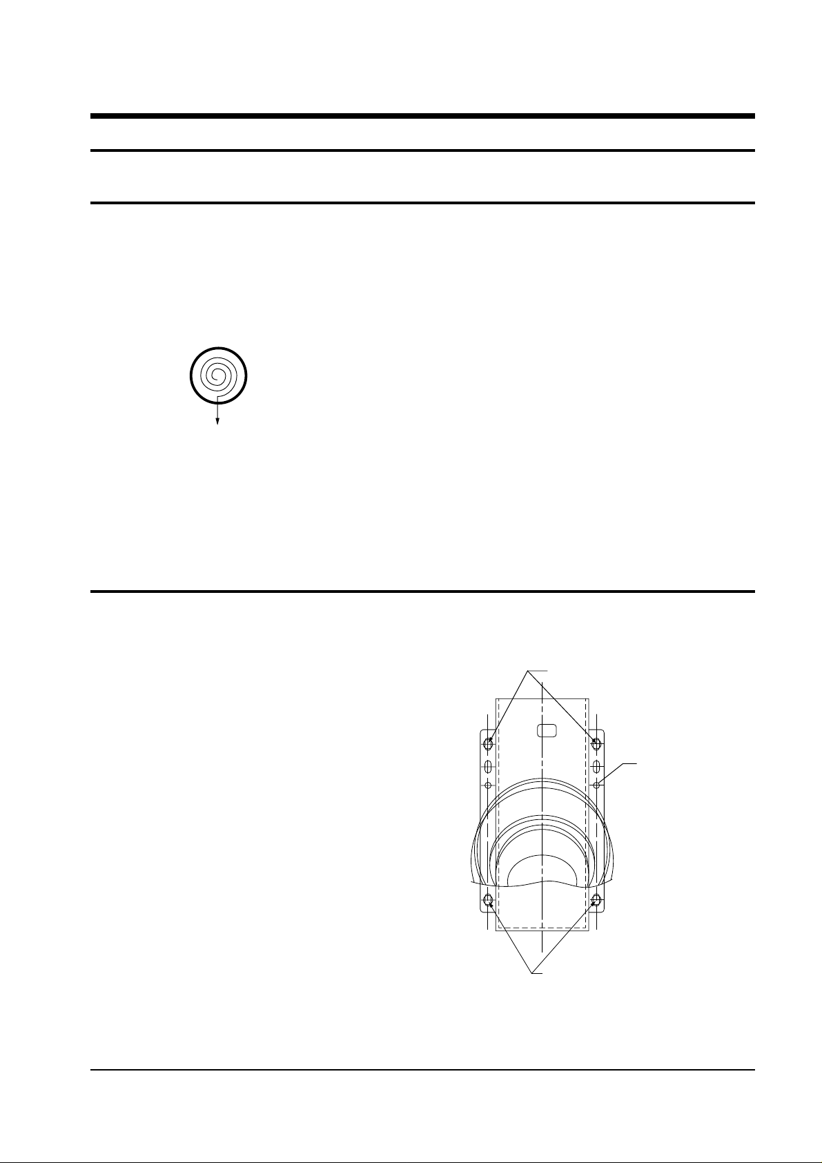
1. Mix the alcohol and ethyl in appropriate proportions.
2. Use a clean cotton cloth or a cleaning paper.
3. Clean the top of the lens by turning it as shown. The pattern starts at the
center and proceeds outward, as shown below:
4. Use minimal pressure when rubbing the mirror. Otherwise, the surface
will be damaged.
5-2 Focus Adjustment for projection Lens
1. Loosen the 4 screws that secure the optical
assembly.
2. After setting the optical assembly on the front
cabinet, secure the unit temporarily using the two
screws.
3. After applying the liquid crystal panel signal,
input a lion head pattern from a pattern
generator.
4. Move the focus adjustment screws right and left
until the liquid crystal picture element
is clearly displayed on the screen.
5. Reposition the optical assembly, and fasten all 4
screws.
6. Check the focus adjustment.
7. Repeat adjustments 1~5, if necessary.
FOCUS SECURING SCREW
FOCUS
ADJUSTMENT
SCREW
FOCUS SECURING SCREW
Fig. 5-1
Page 2
Alignment and Adjustments
5-2 Samsung Electronics
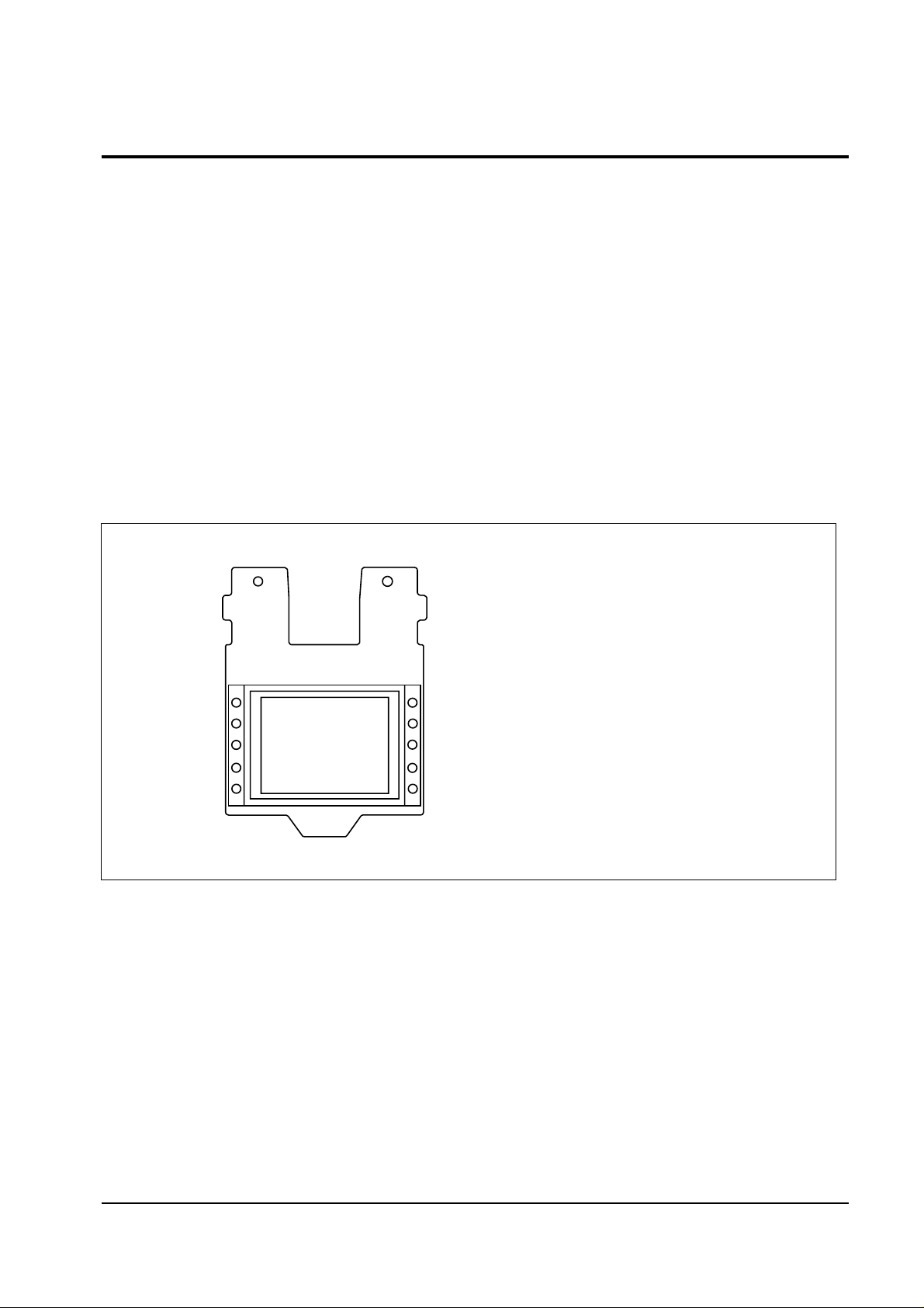
After replacing with the new liquid crystal panel, make sure that the liquid crystal screen center is
aligned with the screen center. If they are not aligned, make the following adjustments:
1. Using a hexagonal wrench, loosen the two screws that secure the liquid crystal panel.
Note: Loosen the screws just until the panel can move easily.
2. Using two fingers, lift the liquid crystal upward. (The screen moves downward.)
3. When moving the liquid crystal panel towards the left, the screen moves right (and vice versa).
5. Repeat adjustments 2~4 until the screen center is aligned vertically and horizontally.
6. Using a hexagonal wrench, refasten the two screws.
5-3 Liquid Crystal Screen Center Adjustment
Fig. 5-2
Page 3
Alignment and Adjustments
Samsung Electronics 5-3
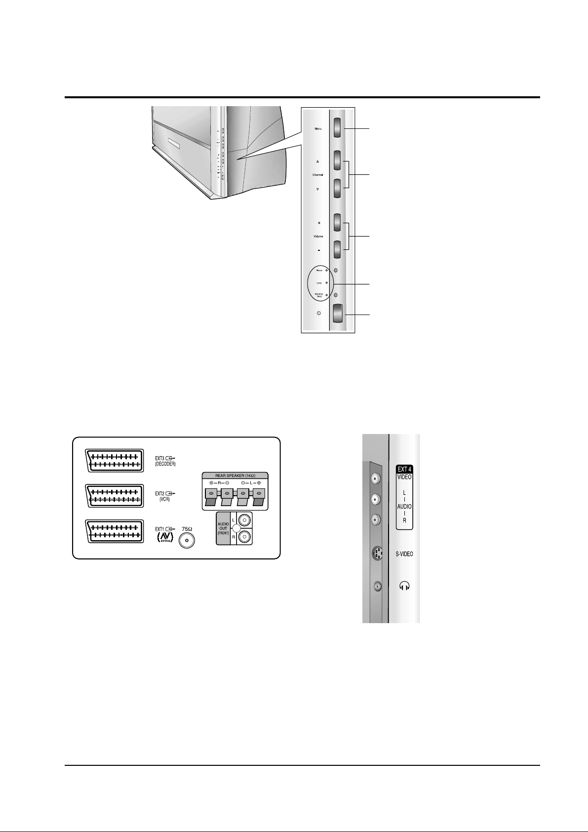
5-4 Side Panel Controls
5-4-1 Rear Panel Jacks
5-4-2 Side input jack
ACCESS TO MENU
PROGRAMME SELECTION
VOLUME ADJUSTMENT
LED INDICATORS
POWER
Page 4
Alignment and Adjustments
5-4 Samsung Electronics
5-5 Service Mode Adjustments
5-5-1 MATRIX IC (TDA4780) Adjustment
No. Item Range Initial value Description
00
01
02
03
04
05
06
07
08
09
10
11
12
RED DRIVE
GREEN DRIVE
BLUE DRIVE
RED CUTOFF
GREEN CUTOFF
BLUE CUTOFF
SUB BRIGHTNESS
SUB CONTRAST
SUB COLOR
PEAK DRIVE LIMIT
P.YC DELAY
SUB TINT
γ CORRECTION
63
63
63
63
63
63
20
20
20
63
15
17
63
19
14
23
32
32
32
11
20
00
53
10
09
00
Adjustment for the R gain
Adjustment for the G gain
Adjustment for the B gain
Adjustment for the R cutoff
Adjustment for the G cutoff
Adjustment for the B cutoff
Adjustment for the brightness
Adjustment for the contrast
Adjusts the color difference signal level of YUVIN 1
Adjustment for the peak drive limit
Adjustment for the P.YC delay
Adjusts the center of tint (0 →R 9 →CENTER 17 →G )
Adjustment for the γ correction
Page 5

Alignment and Adjustments
Samsung Electronics 5-5
5-5-2 LCD Interface IC (CXA1853_A) Adjustment
No. Item Range Initial value Description
00
01
02
03
04
05
06
07
08
09
10
Gamma gain 1
R gamma gain 1
B gamma gain 1
Gamma gain 2
R gamma gain 2
B gamma gain 2
Gamma ctrl 2
Main bright
R main bright
B main bright
White limit
63
63
63
63
63
63
63
63
63
63
63
41
29
48
16
29
36
34
59
36
37
40
Adjusts the gain of black side on the gamma curve (R,G.B)
Adjusts the gain of black side on the gamma curve for R
Adjusts the gain of black side on the gamma curve for B
Adjusts the gain of white side on the gamma curve (R,G.B)
Adjusts the gain of white side on the gamma curve for R
Adjusts the gain of white side on the gamma curve for R
Adjusts the change point of the white side on the gamma curve (R,G,B).
The smaller the value, the more it moves towards white.
Adjust the DC level of R,G,B signal before doing the gamma adjustment.
It determines the change point of the gamma curve. The greater the
value, the darker it gets.
Adjusts the DC level of R before doing the gamma adjustment. It determines the change point of the gamma curve. The greater the value, the
darker it gets.
Adjusts the DC level of B before doing the gamma adjustment. It determines the change point of the gamma curve. The greater the value, the
darker it gets.
Adjusts the limiter voltage of white peak of R,G,B video signal (applied
to LCD). The greater the value, the lower the limiter
voltage becomes.
Page 6

Alignment and Adjustments
5-6 Samsung Electronics
5-5-3 LCD Interface IC (CXA1853_B) Adjustment
No. Item Range Initial value Description
00
01
02
03
04
05
06
07
08
09
10
11
Gamma ctrl 1 off
Black Stretch On
R gamma ctrl 1
B gamma ctrl 1
Sub bright
R sub bright
B sub bright
Common ctrl
Signal center
Sub contrast
R sub contrast
B sub contrast
63
36
63
63
20
63
63
63
63
63
63
63
44
39
33
38
04
38
48
31
18
41
33
33
Adjusts the change point of the black side on the gamma curve
(R,G,B). The greater the value, the more it moves towards black
Adjusts the change point of the back side on the (R,G,B) gamma
curve. Moves the change point to the white side. The value is always
less than the one of the gamma ctrl 1 off.
Adjusts the change point of the back side on the gamma curve for R.
The greater the value, the more it moves towards black.
Adjusts the change point of the black side on the gamma curve for B.
The greater the value, the more it moves towards black.
Adjusts the brightness of R, G, B after doing the gamma adjustment.
No change of the gamma curve. The greater the value, the darker it
gets.
Adjusts the brightness of R after doing the gamma adjustment. No
change on the gamma curve. The greater the value, the darker it
gets.
Adjusts the brightness of B after doing the gamma adjustment. No
change on the gamma curve. The greater the value, the darker it
gets.
Adjusts the common voltage (applied to LCD)
Adjusts the DC level of composite video signals (applied to LCD). Set
the signal center to 7V.
Adjusts the gain of R, G, B (applied to LCD).
Adjusts the gain of R (applied to LCD).
Adjusts the gain of B (applied to LCD).
No. Item Range Initial value Description
00
01
02
LCD h pos
LCD v pos
SH position
255
15
15
106
3
6
Determines the start location of horizontal indication by picture
element.
Determines the start location of vertical indication (within 1H)
Determines the phase of the sample/hold pulse.
5-5-4 LCD CONTROLLER (CXD2443Q) Adjustment
Page 7

Alignment and Adjustments
Samsung Electronics 5-7
No. Item Range Initial value Description
00
01
lamp total time
lamp time
05999
05999
Records total elapsed time (from the time where power is first applied).
Reset not possible
Records total elapsed time (from the point where power is first
applied). Reset (using the cancel key). The lamp time is displayed by
using the Display key. Reset must be done during the set shipment.
Reset must be done after lamp replacement.
5-5-5 Lamp’s Total Hours
5-5-6 Option
No. Item Range Initial value Description
00
01
02
03
04
05
06
07
08
09
10
11
12
13
Epg
Av_link
Palplus
27Mhz external
16 : 9 wide
Dolby prologic
3d sound
S-audio mute
Blue screen
UHF only
Vga
Atm one run
Size key
Vert. peaking
on/off
on/off
on/off
on/off
on/off
on/off
on/off
on/off
on/off
on/off
on/off
on/off
on/off
on/off
off
on
off
on
on
off
on
off
on
off
off
on
on
on
Electronic program guide
Av_link
27Mhz external
16 : 9 wide
Dolby prologic
3d sound
Scart audio mute
Blue screen
UHF only
Vga input
Atm one run (“OFF” for France)
Size key
Vip option
Page 8

Alignment and Adjustments
5-8 Samsung Electronics
5-6-1 LCD Control Board PLL Adjustment
1. Input a color bar signal.
2. Connect CNL06,RPD to an oscilloscope, and
check the waveforms.
(1 V/div, 20 u sec/div)
5-6-2 Matrix IC (TDA4780) Sub Tint Adjustment
1. Input a color bar signal.
2. Connect CNL07 (B output) to an oscilloscope,
and check the waveform.
(0.5 V/div, 20 u sec/div)
5-6-3 Matrix R Output Signal Amplitude
Adjustment (Red Drive)
1. Input a 10-step signal (Color OFF).
2. Connect CNL07 (R output) to an oscilloscope,
and check the waveform.
(0.5 V/div, 10 u sec/div)
3. Adjust the red drive so that the signal amplitude becomes 0.7Vp-p.
4. Adjust the Sub-brightness of TDA4780 so that
the waveform (without sync) is seen as shown
in the figure below.
5-6-4 Matrix G Output Signal Amplitude
Adjustment (Green Drive)
1. Input a 10-step signal (Color OFF).
2. Connect CNL07 (G output) to an oscilloscope,
and check the waveform.
(0.5 V/div, 10 u sec/div)
3. Adjust the green drive so that the signal
amplitude becomes 0.7Vp-p.
5-6- 5 Matrix B Output Signal Amplitude
Adjustment (Blue Drive)
1. Input a 10-step signal (Color OFF).
2. Connect CNL07 (B output) to an oscilloscope,
and check the waveform.
(0.5 V/div, 10 u sec/div)
3. Adjust the blue drive so that the signal amplitude becomes 0.7Vp-p.
5-6-6 Main Brightness Adjustment
1. Input a 10-step signal (Color OFF).
2. Connect LCD CNL08(R1) input to an oscilloscope, and check the waveform.
(2 V/div, 10 u sec/div)
3. Adjust the main brightness so that the Ref
pulse is positioned on the center of signal.
Note : The change point (on gamma curve) is
determined by Ref.
RPD
DC2.8V
5-6 Circuit Adjustments
REF Pulse
Page 9

Alignment and Adjustments
Samsung Electronics 5-9
5-6-7 R Main Brightness & B Main Brightness
Adjustments
1. Input a 5-step signal (Color OFF).
2. Connect CH1 to LCD G1 input and CH2 to
LCD R,B input. (1 V/div, 10 u sec/div)
3. Reverse the CH2 signal, and add CH1 and
CH2 in ADD mode.
4. Adjust R,B main brightness for the waveform
shown below.
Note: The R,B main brightness adjustment should
be done with Gamma
Adjustment OFF (gamma ctrl1 = 63, gamma
ctrl2 = 17).
5-6-8 R Sub-brightness & R Contrast
Adjustments
1. Input a 5-step signal (Color OFF).
2. Connect CH1 to LCD G1 input and CH2 to
LCD R1 input. (1 V/div, 10 u sec/div)
3. Reverse the CH2 signal, and add CH1 and
CH2 in ADD mode.
4. Adjust R sub-contrast and R sub-brightness
waveforms, as shown below:
5-6-9 B Sub-brightness & B Contrast
Adjustments
1. Input a 5-step signal (Color OFF).
2. Connect CH1 to LCD G1 input and CH2 to
LCD B1 input. (1 V/div, 10 u sec/div)
3. Reverse the CH2 signal, and add CH1 and
CH2 in ADD mode.
4. Adjust B sub-contrast and B sub-brightness
waveforms, as shown below:
5-6-10 Gamma Adjustment
1. Input a 5-step signal (Color OFF).
2. Connect LCD G1 input to an oscilloscope.
(2 V/div, 10 u sec/div)
3. Adjust the gamma gain1, gain2 and the
gamma ctrl1, crtl2 for the waveform shown
below.
Brightness Adjustment
Brightness Adjustment
Contrast Adjustment
Brightness Adjustment
Contrast Adjustment
Page 10

Alignment and Adjustments
5-10 Samsung Electronics
5-6-11 Sub-Contrast Adjustment
1. Input a 5-step signal (Color OFF).
2. Connect LCD G1 input to an oscilloscope.
(2 V/div, 10 u sec/div)
3. Adjust the sub-contrast so that the signal level
is 3V, as shown below:
5-6-12 Signal Center Adjustment
1. Input a 5-step signal (Color OFF).
2. Connect LCD G1 input to an oscilloscope, and
check the waveform.
(2 V/div, 10 u sec/div)
3. Set the signal center to 7V.
5-6-13 Common Voltage Adjustment
1. Connect LCD COMMON input to an
oscilloscope, and check the waveform.
(1 V/div, 10 u sec/div)
2. Set the common control to 6.8V.
5-6-14 White Balance Adjustment
1. Input a lion head pattern from a pattern
generator.
2. Adjust the sub-brightness so that the white
cannot be saturated.
3. Adjust R,B contrast for the high light of white
balance.
4. Adjust R,B sub-brightness when the middle
tone is not black and white,but colored.
Repeat adjustments 3 ~ 4 for optimum.
5. Adjust gamma crtl1 for adjusting the brightness of the black side.
6. Adjust R,B gamma crtl1 while checking the
tone of the black side so that any color is not
seen.
7. Repeat adjustments 2 ~ 6, if necessary.
5-6-15 Center Convergence Adjustment
1. Input a lion head pattern from a pattern
generator.
2. Adjust the LCD Horizontal/Vertical POS.
3V
Center 7V
Page 11

Alignment and Adjustments
Samsung Electronics 5-11
1
2
3
4
5
6
5-7 LED Display Check
Picture
Lamp
Stand By
Temp
Status
No
Master Power ON (in the Stand-by Mode)
Normal operation
Lamp is warming up.
The normal picture comes on after 25 seconds.
Air vent cover in the rear of the TV is not properly installed.
Inside temperature of the TV is over normal. Clean the air vent cover
in the rear of the TV. Turn the TV back on after 1 hour.
(see below “Temperature”)
The lamp needs to be replaced.
or
: OFF
: ON
: Blinking
◆ Temperature
Wen the inside temperature of the TV becomes too high, the TV set is automatically turned off.
You will observe the following.
1. “TEMP” LED is blinking for about 5 ~ 6 seconds.
2. The picture is turned to blue screen and “TEMPERATURE” character blinks for about 5 ~ 6 seconds.
3. The power is turned off and “TEMP” LED is blinking for about 20 seconds.
(This is not a TV set failure and normal operation)
 Loading...