

Page 1

Troubleshooting
Samsung Electronics 6-1
6. Troubleshooting
6-1 Service Mode
1. To enter the Service Mode, press the remote-control keys in the following sequence:
Display → Picture Standard → Mute → Power
2. Use the Channel UP/DOWN keys to move within the Service Mode.
3. Use the Vol (+) key and Vol ( - ) key to change data.
(1) Press the Vol (+) key to increase data.
(2) Press the Vol (-) key to decrease data.
4. Use the Power key to exit and store data in memory.
Page 2
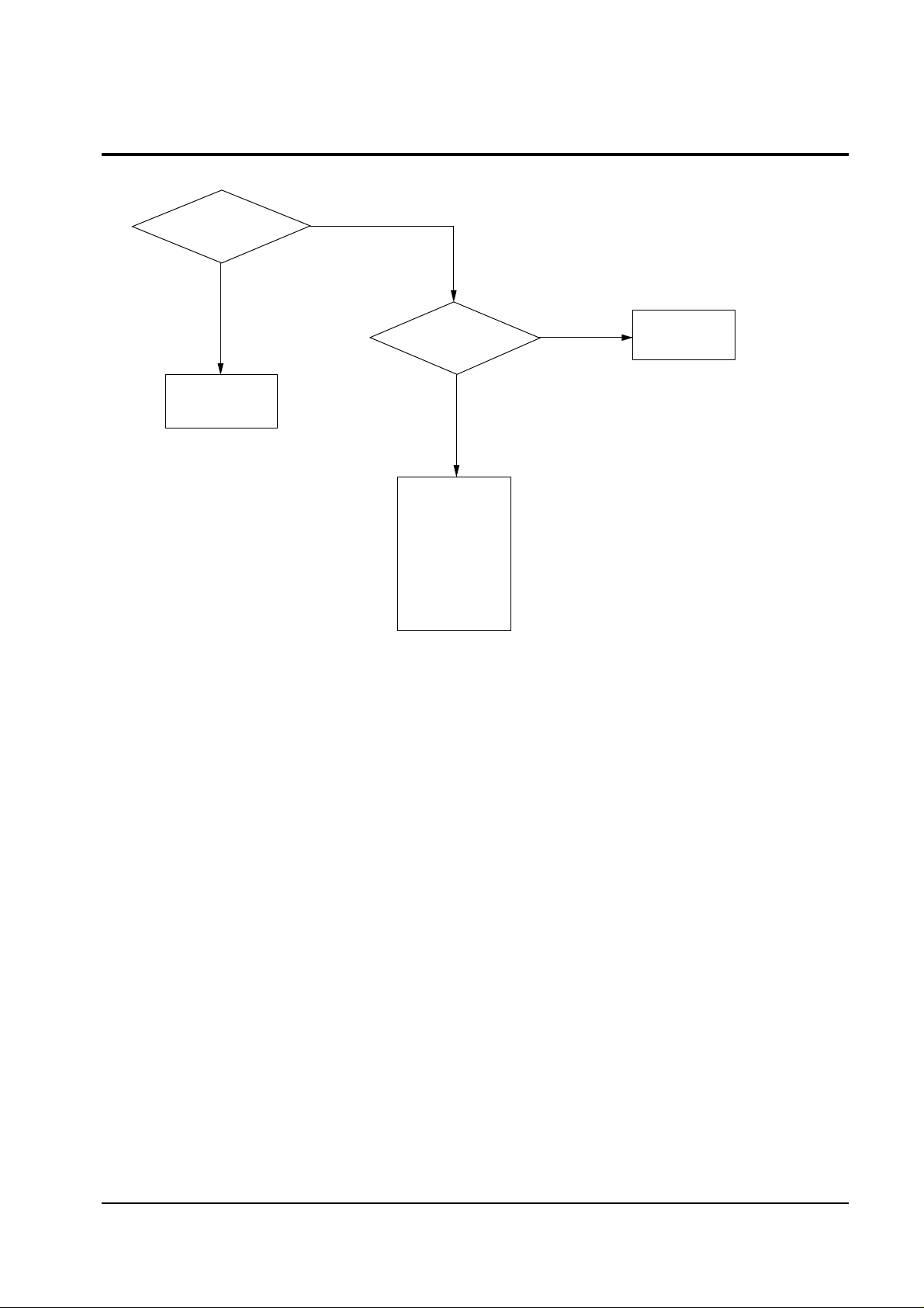
6-2 No Power
Troubleshooting
6-2 Samsung Electronics
No
Yes
Yes
Check Stand-by 5V
on the Main Board
See "6-5 No Standy"
Check/Replace
Tuner
MICOM Module
AUDIO Module
A/V Terminal Board
(TDA6920)
Progressive Module
LCD Control Board
(TDA4780)
Check
SDA1/SCL1
on the Micom
Module
Check LED Operation
See "5-7 LED Display
Check"
No
Page 3

6-3 No Picture
Troubleshooting
Samsung Electronics 6-3
Yes No
Check IC101 (TDA9810)
#10 (AGC), #12 (CVBS)
Check/Replace
IC101, Tuner
Replace
Progressive Module
No
Check Progressive
Module M-Y/CVBS,2Hsync,Vsync,
2Y,2R-Y,2B-Y,Href
Check ICL404 (TDA4780)
#14 (Sand castle pulse)
Yes
Yes
Yes
No
No
Check IC401,402,403
#5 (74HC1230
First check the circuitry
connected to the IC and
replace the IC
No
Check
ICL404(TDA4780)#6(B-Y)
#7(R-Y),#8(Y),#27(SDA)
#28(SCL)
Yes
Yes
No
Check CL129,
130,131 and AC2 5P connector for
#6,7,8 Check AC1 12P and SDA,SCL
output of micom module
for #27,28
Check the circuitry near
ICL404 and replace
micom module
No
Check the circuitry near
ICL404, replace IC201
(TDA4780)
Check ICL404(TDA4780)
#20(B-OUT),#22(G-OUT)
#24(R-OUT)
Check ICL204(CXA1853Q)
#9(R-in),#10(G-in),#11(B-in)
No
No
Check the circuitry near
QL401,QL402,QL403
around of ICL404(TDA4780)
Yes
Check ICL205(CXA2504N)
#23,#25,#27,#33,#35,#37
Yes
Yes
Check/ Replace
CNL04 (24P)
Replace ICL205(CXA2504N)
Page 4
Troubleshooting
6-4 Samsung Electronics
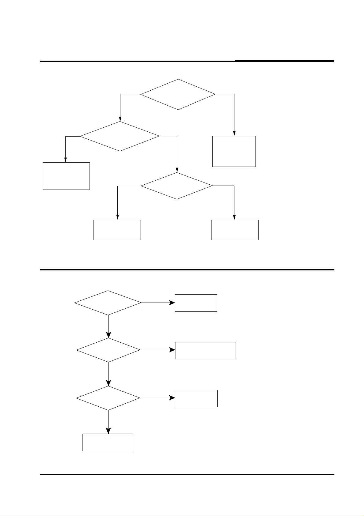
6-4 No Sound
Yes
Yes
No
Check IC601,# 5 (MUTE)
Check/Replace
Q602, Q603
Micom Module
IC601
Check/Replace
IC101
Micom Module
Audio Module
No
Check Audio Module
MAIN-L, SUR, CENTER,
S-RESET, QSS-IN
Check IC604
#9, #14, #15
Check/Replace
IC604
MICOM Module
No
Replace
IC601
Yes
6-5 No Standby (+5V)
Yes
No
No
No
Yes
Yes
Check
the voltage of IC808
pin 5 (over 6V)
Check/Replace
IC808 Regulator
IC (SI-3050C)
Check the AC
power supply of D826
Check the associated
circuitry parts of T802, IC801
Check F801
Replace F801
(AC250V/6.3A)
Check L801,L802, C801,
C802, V801, R801
Page 5
Troubleshooting
Samsung Electronics 6-5
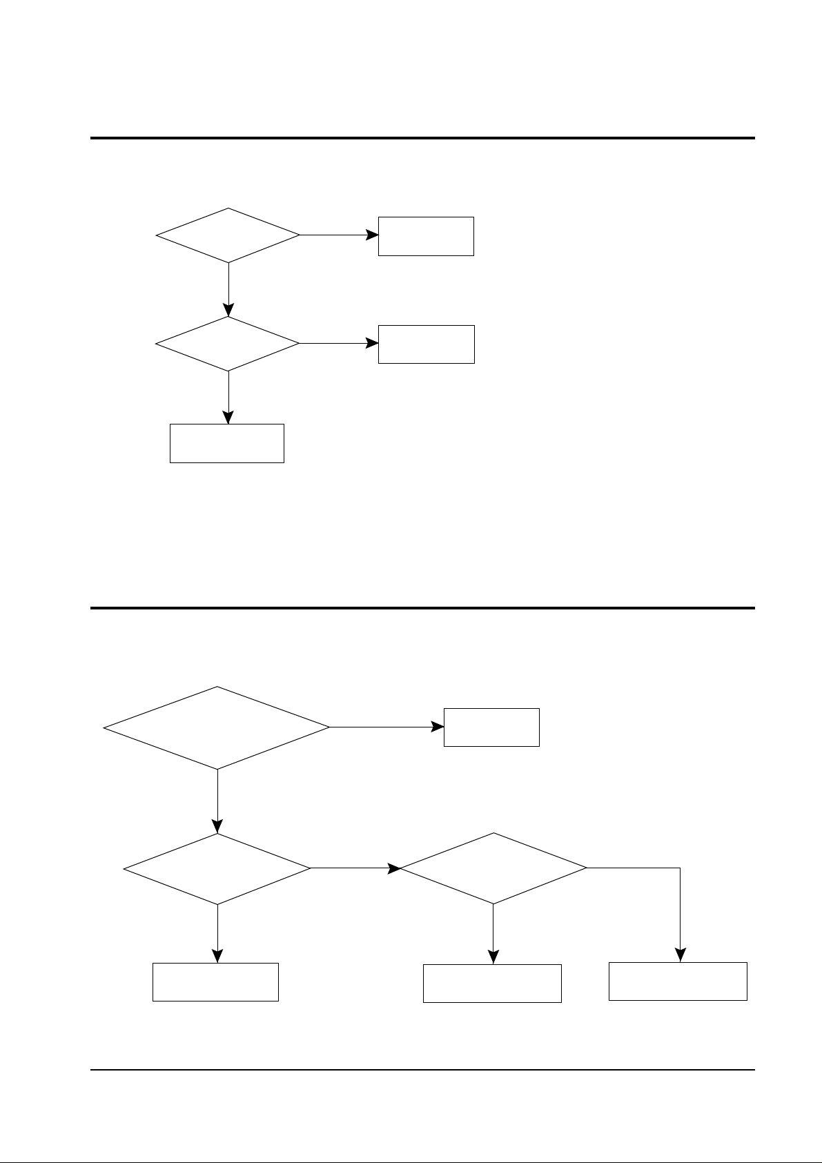
6-6 No FAN Voltage (+8V)
No
No
Yes
Yes
Check
the voltage of
IC805 pin 5 (12V)
Check /Replace
IC805 Regulator
IC (SI-3050C)
Check the voltage
of T801 pin12
Check L811,
D821, C836
Check
T801/Replace trans
6-7 Lamp Does Not Work
Yes
No
No
Yes
Standby/Temp LED,
Picture LED, Lamp LED flicker at
the same time? Or, check the lamp
time (6000 hrs)
Check/Replace
Lamp
Check
the DC voltage of BALLAST
(about 300V)
Check the voltage
of AB1 (connector) pin1 on the
Main Board (over 3.5V)
Check F801 (on the
Power Board), D803, and
surrounding circuitry
Check the voltage
of IC904(SAA1300) pin 6
(over 3.5V)on the Main Board
Check AB1 on the
Ballast Board
No
Yes
Page 6

Troubleshooting
6-6 Samsung Electronics
6-8 Horizontal Sync Flows
No
Yes
Yes
Yes
No
No
Yes
No
Yes
Horizontal Sync Flows
Check
the output of 2H-Sync
from the progressive
module
Replace the
progressive module
Check Connector
Assy AC1
Check the input of
2H-sync to ICL301(CXD2443Q) Pin 13 on
the LCD Control Board
Check ICL402
(74HC123) Pin13,FI302
Check the
voltage of CNL06
RPD (2.8V)
Check voltage of TL301
so that the voltage of
CNL06 RPD is 2.8V
Check
the output of 2H-Sync
HREF to LCD Control
Board
Check the connector to
LCD panel (CNL04)
Page 7

Troubleshooting
Samsung Electronics 6-7
6-9 Vertical Sync Flows
No
Yes
Yes
No
No
Yes
Yes
Vertical Sync Flows
Check
the output of V-Sync
HREF from progressive
module
Replace the
progressive module
Check Connector
Assy AC1
Check the input
of V-Sync to ICL301 Pin 14
on LCD Control Board
Check ICL402
(74HC123) Pin 5
Check
the input of V-Sync
to LCD Control
Board
Check CNL04 (connector
to LCD panel)
 Loading...