

Alignment and Adjustments
Samsung Electronics 4-1
4. Alignment and Adjustments
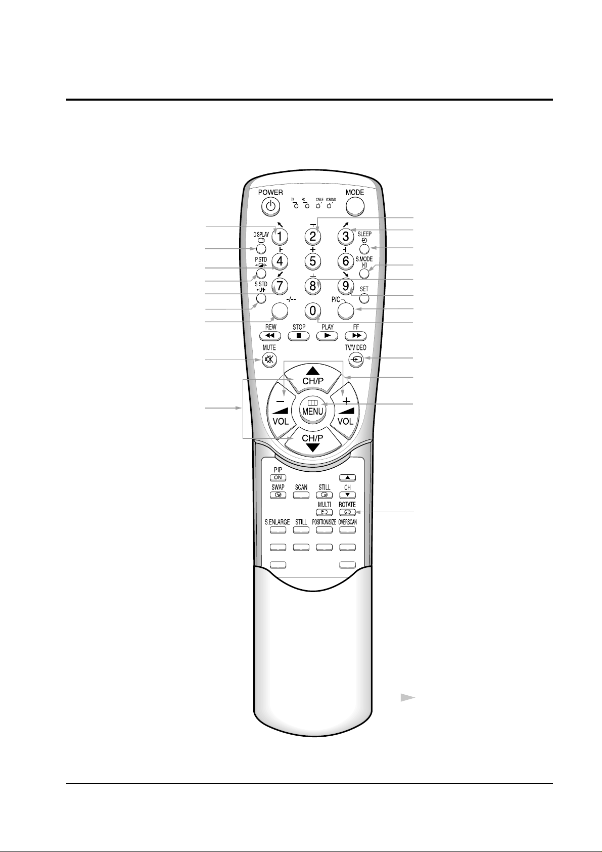
4-1 When entering the service mode:
1. Turn on the TV and then select “STANDARD”on the picture adjustment mode.
2. Turn off the TV (STAND-BY).
3. Enter the service mode by pressing the remote control keys in the following sequence :
DISPLAY→ΜΕΝU→MUTE →Power On
Note : If necessary, re-do steps 1~3.
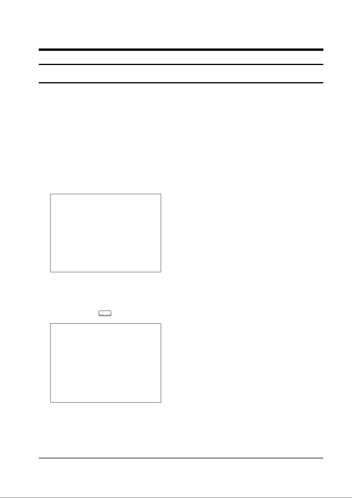
Initial display when the service mode is switched.
SERVICE MODE
GEOMETRICS
PICTURE
PICTURE2
PIP
OPTIONS
RESET
1. When a RF signal is received
MAIN MENU
ZOOM
COMPRESS
FREEZE
SET UP
RESET
EXIT
2. When the PC mode is received
(Press to )
F.MENUF.MENU
Alignment and Adjustments
4-2 Samsung Electronics
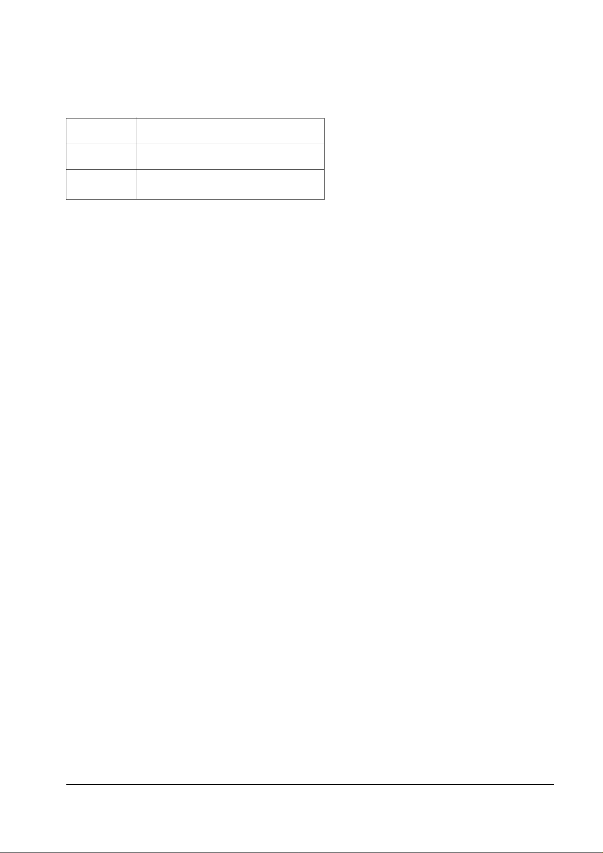
MAIN MENU MENU DISPLAY
CH UP/DOWN Select item by moving cursor
VOL UP/DOWN Decrease or increase the adjustment values
3. Service Mode Control Keys
Note : The PC mode can be switched to the service mode by pressing the F.Mode Key (only
on the factory remote control).
Alignment and Adjustments
Samsung Electronics 4-3
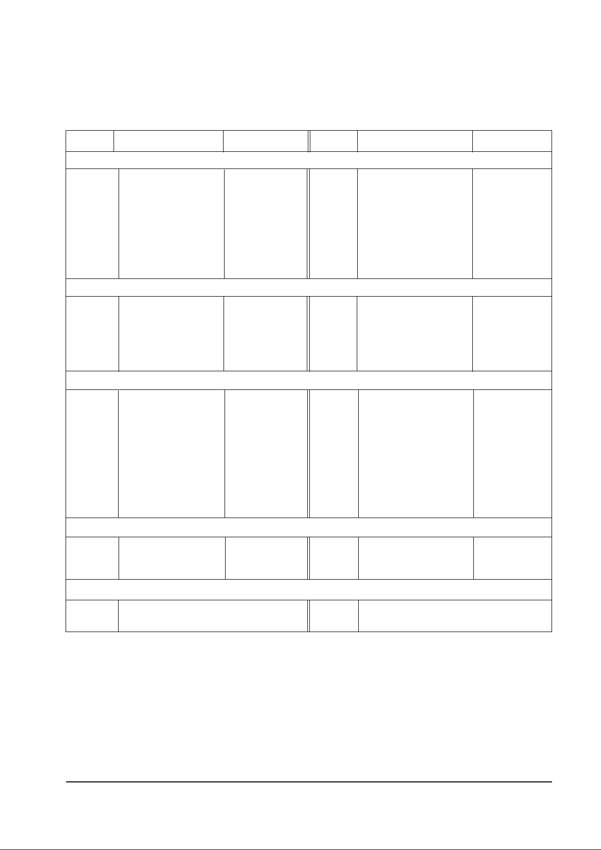
GEOMETRIC ( PAL / NTSC )
VS V-SHIFT 106/124 LOC LO-CORR 128
VA V-SIZE 116/111(Variable) HEH H-EHT 0
VL V-LINEAR 114 VE V-EHT 0
VSC V-S-CORR 104 VAN V-ANGLE 124
HS H-SHIFT 73/77 VBO V-BOW 128
HA H-SIZE 101/112(Variable) HSP H-SYNC-PHASE 138
PPH PIN-PHASE 143/180 --- 0
PAM PIN-AMP 70 --- 0
UPC UP-CORR 128 --- 0
PICTURE
DRI DRIVE-LEVEL 20(Variable) GCT G-CUT OFF 8
SBR SUB-BRIGHT 26(Variable) BCT B-CUT OFF 10(Variable)
RDR R-DRIVE 25(Variable) GAM GAMMA LEVEL 12
GDR G-DRIVE 32 ABL P-ABL LEVEL 15
BDR B-DRIVE 46(Variable) PYD LUMA DELAY 12
RCT R-CUT OFF 4(Variable) SYD SECAM LUMA DELAY 13
PICTURE2
SHU SUB-HUE 7 R2L RGB-2LEVEL 8
SBR SUB-BRIGHT 7 SHP SUB-SHARPNESS 2
R-R R-Y AXIS R-Y 5 SF0 SHARPNESS-F0 2
R-B R-Y AXIS R-Y 10 POV PRE-OVERSHOOT 3
G-R R-Y AXIS R-Y 12 NRL NR-LEVEL 1
G-B R-Y AXIS R-Y 8 DCT DC-TRAN 3
CN1 SUB-CONTRAST1 8 D-N DYNAMIC PICTURE 2
CR1 SUB-COLOR1 8 CEC CEC-LEVEL 3
CN2 SUB-CONTRAST2 10 VML VM-LEVEL 2
CR2 SUB-COLOR2 4 ABL ABL-MODE 2
R1L RGB-1LEVEL 6
PIP
PCN CONTRAST 3(Variable)
PHP POS-HOR 55(Variable)
PVP POS-VER 27(Variable)
OPTION
TTX OFF PC ON
LNA ON SCART2 OFF
ITEM
FUNCTION INITIAL VALUE
ITEM
FUNCTION INITIAL VALUE
PAL (43”)
Alignment and Adjustments
4-4 Samsung Electronics
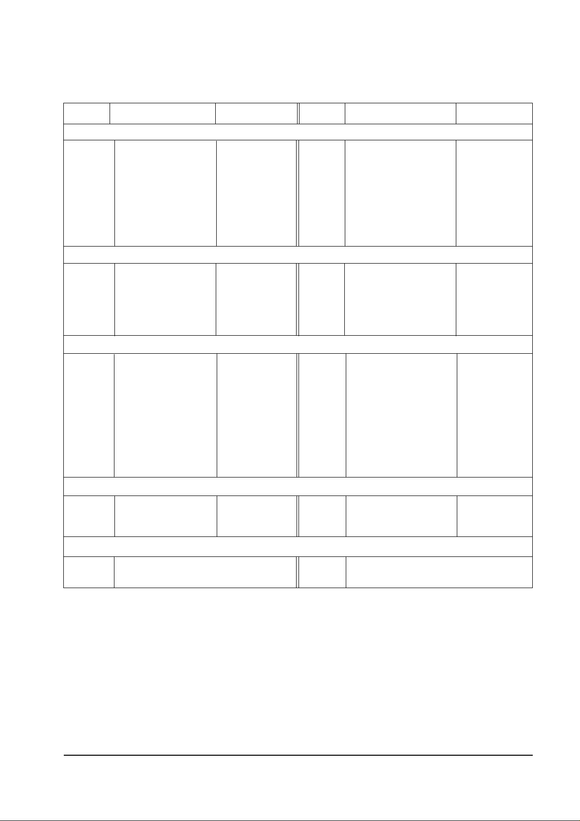
PAL (53”)
GEOMETRIC ( PAL / NTSC )
VS V-SHIFT 106/124 LOC LO-CORR 128
VA V-SIZE 86/90(Variable) HEH H-EHT 0
VL V-LINEAR 114 VE V-EHT 0
VSC V-S-CORR 104 VAN V-ANGLE 124
HS H-SHIFT 73/77 VBO V-BOW 128
HA H-SIZE 91/95(Variable) HSP H-SYNC-PHASE 138
PPH PIN-PHASE 143/180 --- 0
PAM PIN-AMP 70 --- 0
UPC UP-CORR 128 --- 0
PICTURE
DRI DRIVE-LEVEL 20(Variable) GCT G-CUT OFF 8
SBR SUB-BRIGHT 26(Variable) BCT B-CUT OFF 10(Variable)
RDR R-DRIVE 25(Variable) GAM GAMMA LEVEL 12
GDR G-DRIVE 32 ABL P-ABL LEVEL 15
BDR B-DRIVE 46(Variable) PYD LUMA DELAY 12
RCT R-CUT OFF 4(Variable) SYD SECAM LUMA DELAY 13
PICTURE2
SHU SUB-HUE 7 R2L RGB-2LEVEL 8
SBR SUB-BRIGHT 7 SHP SUB-SHARPNESS 2
R-R R-Y AXIS R-Y 5 SF0 SHARPNESS-F0 2
R-B R-Y AXIS R-Y 10 POV PRE-OVERSHOOT 3
G-R R-Y AXIS R-Y 12 NRL NR-LEVEL 1
G-B R-Y AXIS R-Y 8 DCT DC-TRAN 3
CN1 SUB-CONTRAST1 8 D-N DYNAMIC PICTURE 2
CR1 SUB-COLOR1 8 CEC CEC-LEVEL 3
CN2 SUB-CONTRAST2 10 VML VM-LEVEL 2
CR2 SUB-COLOR2 4 ABL ABL-MODE 2
R1L RGB-1LEVEL 6
PIP
PCN CONTRAST 3(Variable)
PHP POS-HOR 55(Variable)
PVP POS-VER 27(Variable)
OPTION
TTX OFF PC ON
LNA ON SCART2 OFF
ITEM
FUNCTION INITIAL VALUE
ITEM
FUNCTION INITIAL VALUE
Alignment and Adjustments
Samsung Electronics 4-5
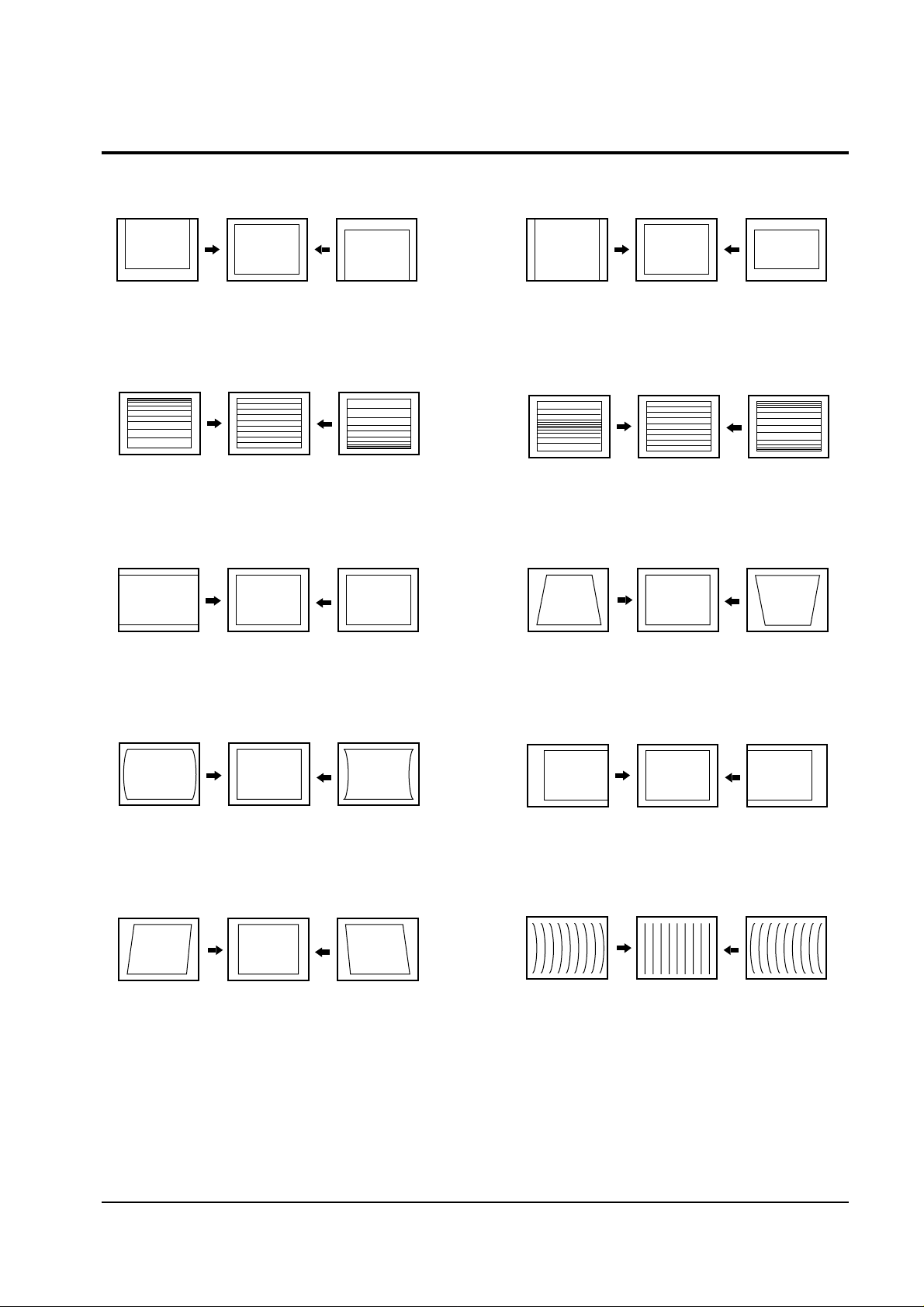
4-2 Screen Change (When adjusting I2C Bus Geometric items)
8
PIN PHASE
10 V BOW
5 V ANGLE
4
PIN AMP
2 V LINEARITY
6 V SIZE
3 H SIZE
9 H SHIFT
7 V - S - CORRECTION
1 V SHIFT
Alignment and Adjustments
4-6 Samsung Electronics
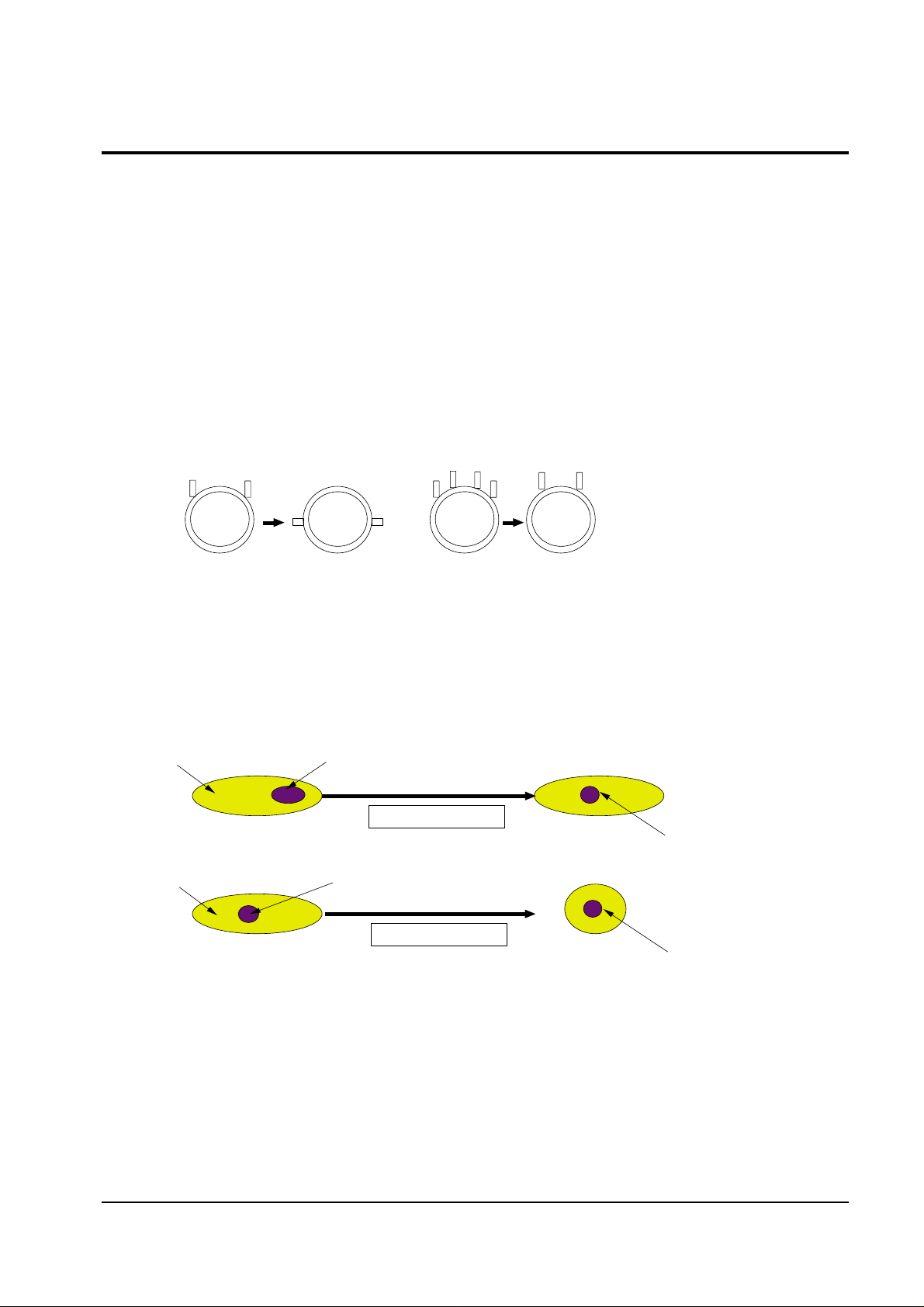
4-3 Beam Alignment
PRECAUTION
1. Input a crosshatch and dot pattern.
2. Select the “STANDARD” video mode.
3. Warm up the TV for at least 10 minutes.
4. Connect an audio oscillator to the pin jig between GT401~GT402 (located on the deflection
PCB) and GND.
5. Determine the ZERO-magnet area (using the beam-alignment CY)
6. Check the squarewave at the point where the focus is misaligned (Use an audio oscillator).
ADJUSTMENT
1. Cover the Red and Blue lenses.
2. Adjust the Green lens as shown in the figures below
3. Adjust the G-Focus until any light around the core disappears.
4. Cover the Green and Blue lenses.
5. Adjust the Red lens using the same method as with the Green lens.
6. Note: The Blue lens is not adjusted because its focus varies little (VM-coil is installed).
7. After the adjustments are completed, disconnect the jig pin connector.
(Creation of CPM Zero Magnet)
(Creation of the 2-pole/4-pole zero magnets)
G-FOCUS
CORE
(Varying G-Focus Pack)
Varying the 2-pole of VM
(Positioning the Core in the Center)
Varying the 4-pole of VM
CORE
G-FOCUS
(When VM 2-Pole Adjustment is completed)
(Adjust until the light around
the core becomes a circle)

Alignment and Adjustments
Samsung Electronics 4-7
4-4 Other Adjustments
4-4-1 Screen Adjustment
1. Warm up the TV for at least 30 minutes.
2. Turn to the Video Mode (No Signal) using a
remote-control.
3. Connect an oscilloscope to RK,GK,BK.
4. Adjust the VR (VR501, VR531, VR561) screen
so that RK, GK, BK pulse is 20Vp-p each.
(Turn the R,G,B VR screen fully
counterclockwise in the area of each flyback
line.)
4-4-2 White Balance Adjustment
1. Select the “STANDARD” video mode.
2. Input 100% white pattern.
3. In the stand-by mode, press the remote-control
keys in the following sequence:
DISPLAY→ΜΕΝU→MUTE →Power On
4. Warm up the TV for at least 30 minutes.
5. Input a 10-step signal.
6. R-cut off, B-cut off, and G-cut off by pressing
the Volume +/- keys.
7. Adjust the low light with viewing the dark
side of the screen.
8. Select R-drive, G-drive, and B-drive by
pressing the Volume +/- keys.
9. Adjust the high light with viewing the light
side of the screen.
10. If necessary, redo adjustments 6~9.
11. Press the Menu key to exit.
4-4-3 Sub-Brightness Adjustment
1. Input a sub-brightness adjustment signal.
(TOSHIBA PATTERN)
2. In the stand-by mode, press the remote-control
keys in the following sequence :
DISPLAY→ΜΕΝU→MUTE →Power On
3. Select SBT by pressing the Volume +/- keys.
4. Adjust so that the 7th step on the right side of
the screen is not seen (Use the Volume +/keys).
5. Press the Menu key to exit.
4-4-4 High Voltage (31KV) Check
PRECAUTION
1. Input a lion head pattern.
2. Select “STANDARD” video mode.
3. Warm up the TV for at least 10 minutes.
4. Use a 1000:1 probe.
ADJUSTMENT
1. Connect the (+) terminal of the 1000:1 probe to
the high voltage distributor and the (-)
terminal to GND (located on the deflection
board).
2. Adjust VR471 (located on the deflection board)
so that the digital meter indicates
DC 31V ± 0.1V.
Alignment and Adjustments
4-8 Samsung Electronics
4-4-5 F.S. (Fail Safe) Circuit Check
Note : The F.S. Circuit check must be performed
after servicing.
1. Turn on the TV.
2. Select the “STANDARD” video mode.
3. Short GT18, GT17 (located on the
Convergence PCB). Then, both sound and
picture disappear. (Note: Even if the shorted
terminals are removed, both sound and
picture do not appear. This proves the F.S.
circuit is working. )
4. To restore both sound and picture, turn off the
TV and reset it after about 30 seconds.
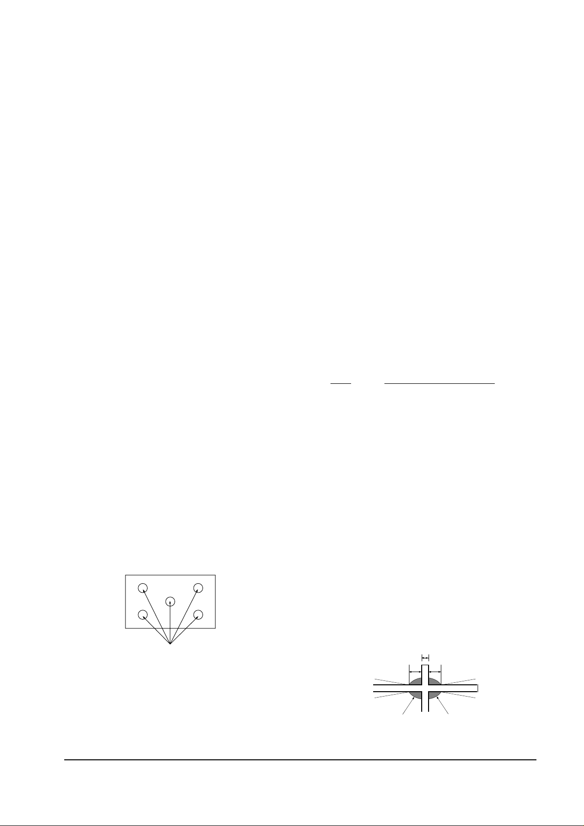
4-4-6 Static Focus Adjustment
PRECAUTION
1. Select the “STANDARD” video mode.
2. Input a crosshatch pattern.
3. Cover the lenses that are not being adjusted.
4. Connect a convergence jig and read data.
5. Adjust the lens for best focus.
(See Fig, 4-1, next page)
STATIC FOCUS (CONTINUED)
Vary the focus pack VR (Red, Blue) on the
front cabinet. Adjust the TV for best possible
focus around the center of the crosshatch
pattern, without losing overall screen balance.
Figure Crosshatch Pattern
Examine these points together.
4-4-7 Lens Focus Adjustment
PRECAUTIONS
1. Do this adjustment after the static focus
adjustment and the tilt adjustment.
2. Select the “STANDARD” video mode.
(Contrast:64, Brightness:32)
3. Input a crosshatch pattern.
ADJUSTMENT
1. Loosen the lens screws.
2. Cover the two lenses that are not being
adjusted.
3. Adjust the lens, observing the color aberration
vertically and horizontally within 3 blocks of
the center of the crosshatch pattern.
4. When the lens is turned clockwise, the color
aberration will change as follows:
Lens Color Aberration Change
R Orange - Crimson
G Blue - Red
B Purple - Green
5. Green lens adjustment:
Set the lens at the point where Blue just
changes to Red. If the color aberration is
irregular throughout the picture screen, adjust
the lens to show Red color aberration
(approximately 1~3 mm area) within a 3-block
grid around the horizontal center-line. If the
color aberration is irregular, adjust the lens as
shown in the diagram below. (Accurate
alignment of Green is important for overall
color quality.)
6. Red lens adjustment
Set the Red lens at the point where Orange
becomes Crimson.
7. Blue lens adjustment
Set the Blue lens at the point where Purple
becomes Green.
P
L1
L2
RED ABERRATION
BLUE ABERRATION
L1, L2 < P
_
Fig. 4-1 Crosshatch Pattern.
Fig. 4-2 Color Aberration
Examine these points together
Alignment and Adjustments
Samsung Electronics 4-9
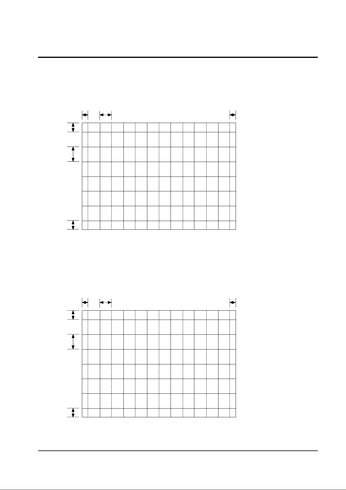
4-5 Screen-Jig
43J5 Screen Size : X 873, Y 655
16. 34mm 70. 03 mm
41.68mm
95.27mm
16.34mm
41.68mm
*
(X:374=7 2+30 12, Y:220=14 2+32 6)
*
*
*
4-5-1 43J5 Convergence Jig Spec
53J5 Screen Size : X 1087, Y81 7
20.34mm 87.19mm 20.34mm
51.99mm
18.84mm
51.99mm
1
(X:374=7 2+30 12, Y:220=14 2+32 6)
*
*
*
*
4-5-2 53J5 Convergence Jig Spec
Alignment and Adjustments
4-10 Samsung Electronics
4-6 Remote Control for Servicing (Convergence Mode)
FACTORY
CONV.
ESCAPE
R/B
3SPEED
F.MENU
Factory Data Select Button
Last Data Save Button
Convergence Pattern Left Move Button
Save Button
G-Select
B-Select
B-Mute
G-Mute
Move Cursor Forward
Convergence Data
Increase, decrease button
Convergence Data Zero Button
Test/Normal
Line Shift
R-Select
Exit Button
R-Mute
Move Cursor Reverse
Convergence Picture
Move Button
Operation of remote
control may be affected
by bright artificial light
near to the TV set.
Convergence Pattern Right Move Button
Data Shift Button
(After PAL Adjustments are
Completed, Press to transmit
data to the NTSC mode)
H/V Direction Select Button
 Loading...