

Samsung sp43j5hfx service manual
PROJECTION TV RECEIVER
Chassis : J51A(REV. 1)
Model : SP43J5HFX/SED
SP43J5HFX/RAD
SP53J5HFX/RAD
SP61J5HFX/RAD
PROJECTION TV RECEIVER CONTENTS
Precautions
Reference Information
Specifications
Alignment and Adjustments
Troubleshooting
Exploded View and Parts List
Electrical Parts List
Block Diagrams
Wiring Diagram
Schematic Diagrams
1.
2.
3.
4.
5.
6.
7.
8.
9.
10.
Alignment and Adjustments
Samsung Electronics 4-1
4. Alignment and Adjustments
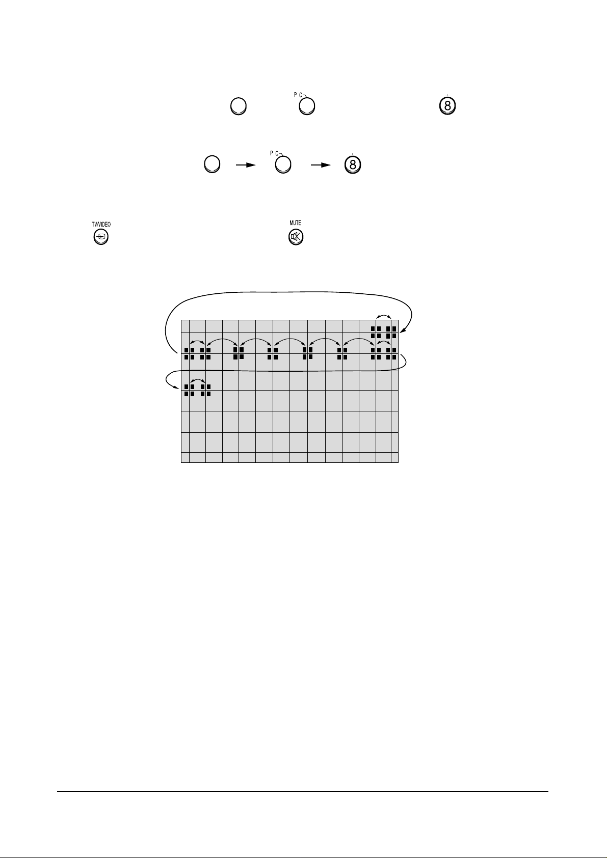
4-1 When entering the service mode:
1. Turn on the TV and then select “STANDARD”on the picture adjustment mode.
2. Turn off the TV (STAND-BY).
3. Enter the service mode by pressing the remote control keys in the following sequence :
DISPLAY→ΜΕΝU→MUTE →Power On
Note : If necessary, re-do steps 1~3.
Initial display when the service mode is switched.
SERVICE MODE
GEOMETRICS
PICTURE
PICTURE2
PIP
OPTIONS
RESET
1. When a RF signal is received
MAIN MENU
ZOOM
COMPRESS
FREEZE
SET UP
RESET
EXIT
2. When the PC mode is received
(Press to )
F.MENU

Alignment and Adjustments
4-2 Samsung Electronics
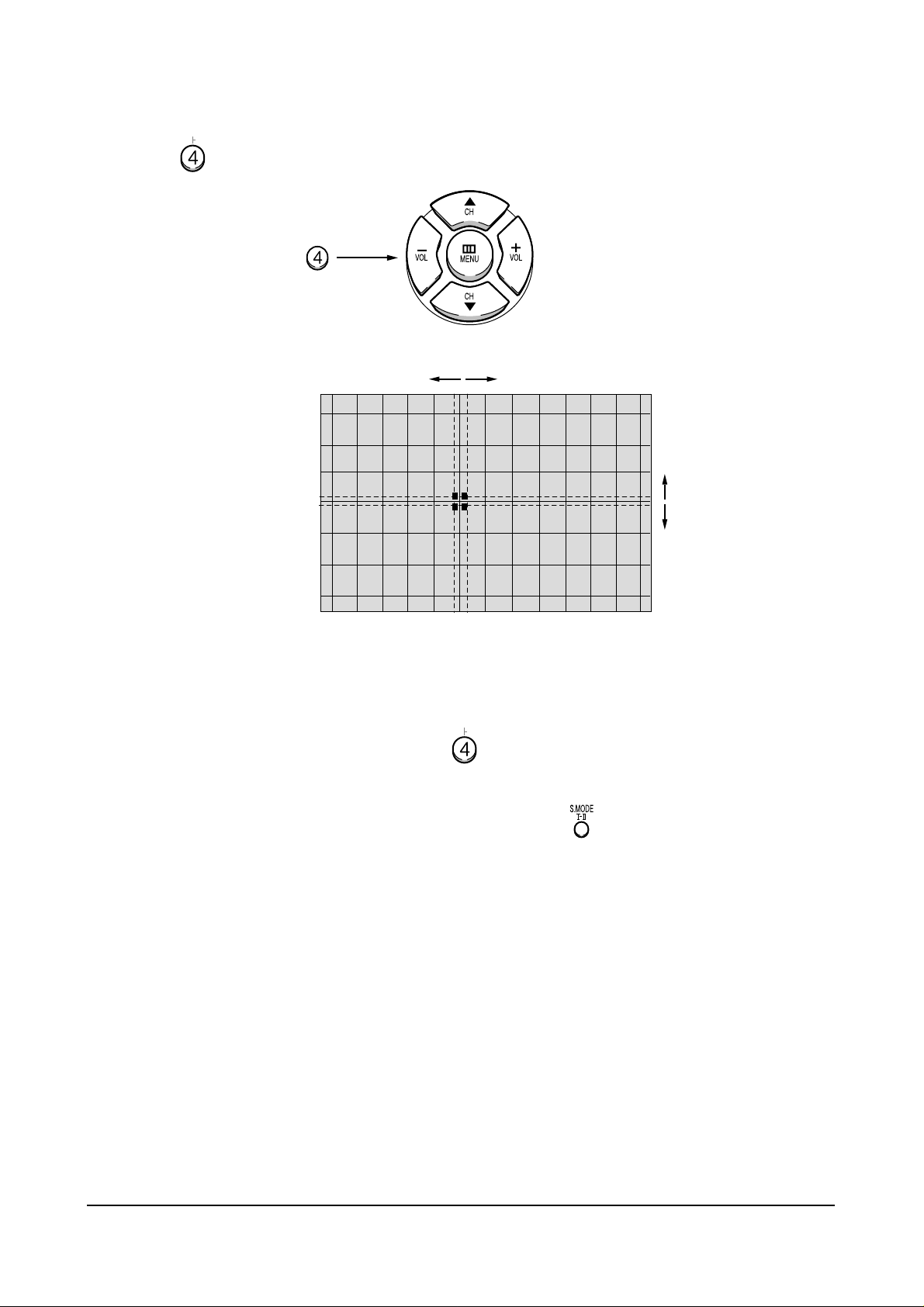
MAIN MENU MENU DISPLAY
CH UP/DOWN Select item by moving cursor
VOL UP/DOWN Decrease or increase the adjustment values
3. Service Mode Control Keys
Note : The PC mode can be switched to the service mode by pressing the F.Mode Key (only
on the factory remote control).
Alignment and Adjustments
Samsung Electronics 4-3
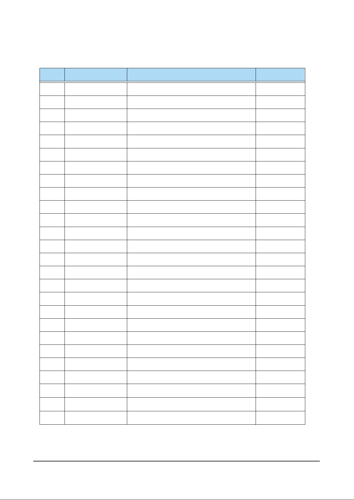
ITEM
FUNCTION INITIAL VALUE
ITEM
FUNCTION INITIAL VALUE
PAL (43”)
VS
VA
VL
VSC
HS
HA
PPH
PAM
UPC
V-SHIFT
V-SIZE
V-LINEAR
V-S-COLOR
H-SHIFT
H-SIZE
PIN-PHASE
PIN-AMP
UP-CORR
GEOMETRIC(PAL/NTSC)
PICTURE
PICTURE2
SBR
RDR
GDR
BDR
RCT
GCT
SHC
R-R
R-B
G-R
G-B
SCN
SCR
HWD
HTM
SHP
SUB-BRIGHT
R-DRIVE
G-DRIVE
B-DRIVE
R-CUT OFF
G-CUT OFF
SUB-HUE
R-Y AXIS R-Y
R-Y AXIS R-Y
R-Y AXIS R-Y
R-Y AXIS R-Y
SUB-CONTRAST
SUB-COLOR
HSYNC WIDTH
HSYNC-TIME-MASK
SUB-SHARPNESS
106/124
60/76(Variable)
114
104
73/77
78/86(Variable)
143/180
70
128
20(Variable)
22(Variable)
31
37(Variable)
9(Variable)
31
7
3
7
15
2
7(Variable)
15
1
1
3
LOC
HEH
VE
VAN
VBO
HSP
--
--
--
LO-CORR
H-EHT
V-EHT
V-ANGLE
V-BOW
H-SYNC-PHASE
128
0
0
124
128
138
0
0
0
BCT
GAM
ABM
ATH
PYD
SYD
B-CUT OFF
GAMMA LEVEL
ABL MODE
ABL Threshold
PAL/NT Y/C DELAY
SECAM Y/C DELAY
31(Variable)
12
1
1
10
10
SFO
LTI
CTI
POV
VML
VMD
DCT
DNP
BPF
HPF
SHARPNESS-FO
LUMINANCE
CHROMINANCE
PRE-OVERSHOOT
VM-LEVEL
VM-DELAY
DC-TRAN
AUTO PEDESTAL
BAND PASS FILTER
HIGH PASS FILTER
2
2
1
3
2
3
3
3
12
10
PIP
PCN
PHP
PVP
CONTRAST
POS-HOR
POS-VER
8(Variable)
55(Variable)
27(Variable)
OPTION
LANGUAGE
TTX
LNA
OFF, WEST/ARABIC, EAST/FARSI
ON,OFF
PC
SCART2
THAI
ON, OFF
OFF, TV OUT, MONITOR OUT
ON, OFF
MULTI-12
MidEast
Asia
Russia
M. Europe
Eng, Arab, French, Thai, Russian, Croatian, Polish, Turkish, Hungaran, Iran, Pakistan, Hindi
Eng, Arab, French, Turkish, Iran, Pakistan
Eng, Thai, Hindi
Eng, Russia
Eng, Croatian, Polish, Hungaran
Alignment and Adjustments
4-4 Samsung Electronics
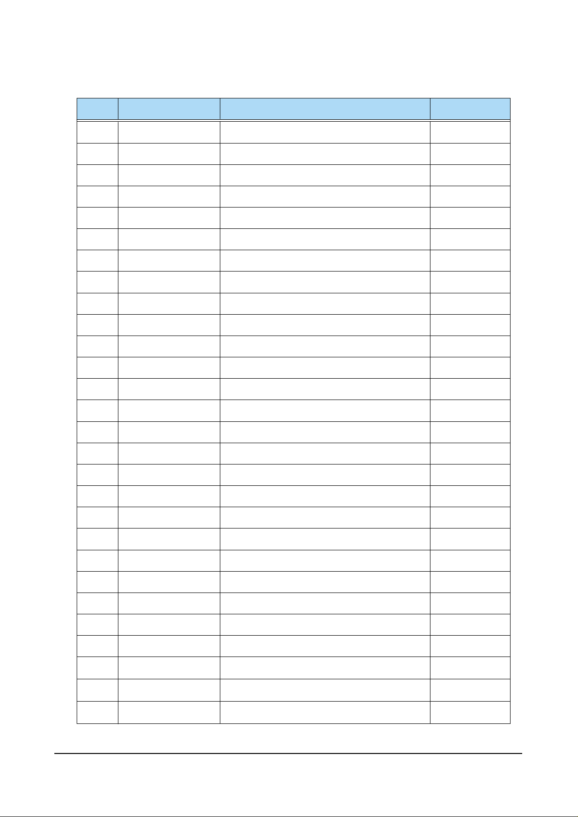
ITEM
FUNCTION INITIAL VALUE
ITEM
FUNCTION INITIAL VALUE
PAL (53”)
VS
VA
VL
VSC
HS
HA
PPH
PAM
UPC
V-SHIFT
V-SIZE
V-LINEAR
V-S-COLOR
H-SHIFT
H-SIZE
PIN-PHASE
PIN-AMP
UP-CORR
GEOMETRIC(PAL/NTSC)
PICTURE
PICTURE2
SBR
RDR
GDR
BDR
RCT
GCT
SHC
R-R
R-B
G-R
G-B
SCN
SCR
HWD
HTM
SHP
SUB-BRIGHT
R-DRIVE
G-DRIVE
B-DRIVE
R-CUT OFF
G-CUT OFF
SUB-HUE
R-Y AXIS R-Y
R-Y AXIS R-Y
R-Y AXIS R-Y
R-Y AXIS R-Y
SUB-CONTRAST
SUB-COLOR
HSYNC WIDTH
HSYNC-TIME-MASK
SUB-SHARPNESS
106/124
72/83(Variable)
114
104
73/77
79/86(Variable)
143/180
70
128
19(Variable)
15(Variable)
31
29(Variable)
17(Variable)
31
7
3
7
15
2
13(Variable)
15
1
1
3
LOC
HEH
VE
VAN
VBO
HSP
--
--
--
LO-CORR
H-EHT
V-EHT
V-ANGLE
V-BOW
H-SYNC-PHASE
128
0
0
124
128
138
0
0
0
BCT
GAM
ABM
ATH
PYD
SYD
B-CUT OFF
GAMMA LEVEL
ABL MODE
ABL THRESHOLD
PAL/NT Y/C DELAY
SECAM Y/C DELAY
28(Variable)
12
1
1
10
10
SFO
STI
CTI
POV
VML
VMD
DCT
DNP
BPF
HPF
SHARPNESS-FO
LUMINANCE
CHROMINANCE
PRE-OVERSHOOT
VM-LEVEL
VM-DELAY
DC-TRAN
AUTO PEDESTAL
BAND PASS FILTER
HIGH PASS FILTER
2
2
1
3
2
3
3
3
12
10
PIP
PCN
PHP
PVP
CONTRAST
POS-HOR
POS-VER
8(Variable)
55(Variable)
27(Variable)
OPTION
LANGUAGE
TTX
LNA
OFF, WEST/ARABIC, EAST/FARSI
ON,OFF
PC
SCART2
THAI
ON, OFF
OFF, TV OUT, MONITOR OUT
ON, OFF
MULTI-12
MidEast
Asia
Russia
M. Europe
Eng, Arab, French, Thai, Russian, Croatian, Polish, Turkish, Hungaran, Iran, Pakistan, Hindi
Eng, Arab, French, Turkish, Iran, Pakistan
Eng, Thai, Hindi
Eng, Russia
Eng, Croatian, Polish, Hungaran

Alignment and Adjustments
Samsung Electronics 4-5
ITEM
FUNCTION INITIAL VALUE
ITEM
FUNCTION INITIAL VALUE
PAL (61”)
VS
VA
VL
VSC
HS
HA
PPH
PAM
UPC
V-SHIFT
V-SIZE
V-LINEAR
V-S-COLOR
H-SHIFT
H-SIZE
PIN-PHASE
PIN-AMP
UP-CORR
GEOMETRIC(PAL/NTSC)
PICTURE
PICTURE2
SBR
RDR
GDR
BDR
RCT
GCT
SHC
R-R
R-B
G-R
G-B
SCN
SCR
HWD
HTM
SHP
SUB-BRIGHT
R-DRIVE
G-DRIVE
B-DRIVE
R-CUT OFF
G-CUT OFF
SUB-HUE
R-Y AXIS R-Y
R-Y AXIS R-Y
R-Y AXIS R-Y
R-Y AXIS R-Y
SUB-CONTRAST
SUB-COLOR
HSYNC WIDTH
HSYNC-TIME-MASK
SUB-SHARPNESS
106/124
90/94(Variable)
114
104
73/77
62/74(Variable)
143/180
70
128
25(Variable)
8(Variable)
31
32(Variable)
16(Variable)
31
7
3
7
15
2
13(Variable)
15
1
1
3
LOC
HEH
VE
VAN
VBO
HSP
--
--
--
LO-CORR
H-EHT
V-EHT
V-ANGLE
V-BOW
H-SYNC-PHASE
128
0
0
124
128
138
0
0
0
BCT
GAM
ABM
ATH
PYD
SYD
B-CUT OFF
GAMMA LEVEL
ABL MODE
ABL Threshold
PAL/NT Y/C DELAY
SECAM Y/C DELAY
23(Variable)
12
1
1
10
10
SFO
STI
CTI
POV
VML
VMD
DCT
DNP
BPF
HPF
SHARPNESS-FO
LUMINANCE
CHROMINANCE
PRE-OVERSHOOT
VM-LEVEL
VM-DELAY
DC-TRAN
AUTO PEDESTAL
BAND PASS FILTER
HIGH PASS FILTER
2
2
1
3
2
3
3
3
12
10
PIP
PCN
PHP
PVP
CONTRAST
POS-HOR
POS-VER
8(Variable)
55(Variable)
27(Variable)
OPTION
LANGUAGE
TTX
LNA
OFF, WEST/ARABIC, EAST/FARSI
ON,OFF
PC
SCART2
THAI
ON, OFF
OFF, TV OUT, MONITOR OUT
ON, OFF
MULTI-12
MidEast
Asia
Russia
M. Europe
Eng, Arab, French, Thai, Russian, Croatian, Polish, Turkish, Hungaran, Iran, Pakistan, Hindi
Eng, Arab, French, Turkish, Iran, Pakistan
Eng, Thai, Hindi
Eng, Russia
Eng, Croatian, Polish, Hungaran
Alignment and Adjustments
4-6 Samsung Electronics
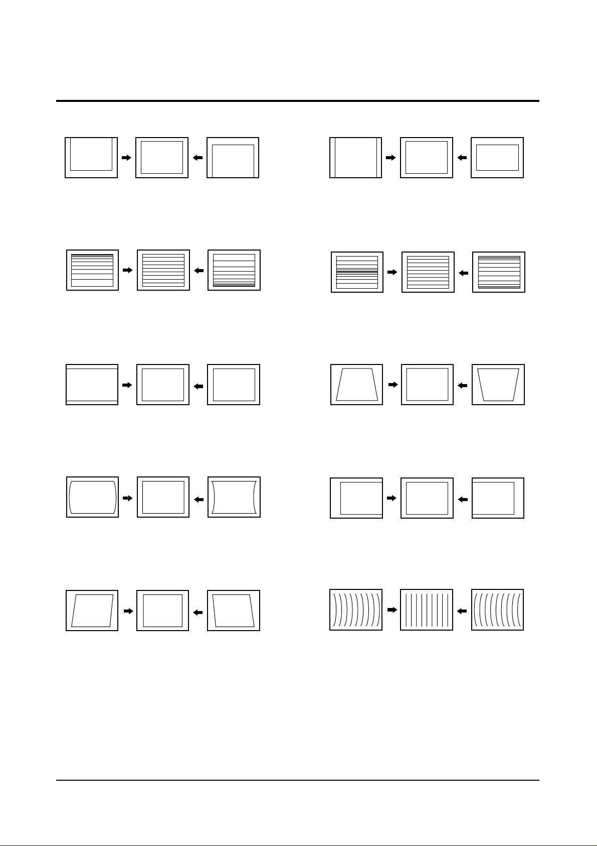
4-2 Screen Change (When adjusting I2C Bus Geometric items)
1 V SHIFT
6 V SIZE
2 V LINEARITY
3 H SIZE
4
PIN AMP
7 V - S - CORRECTION
8
PIN PHASE
9 H SHIFT
5 V ANGLE
10 V BOW

Alignment and Adjustments
Samsung Electronics 4-7
4-3 Beam Alignment
PRECAUTION
1. Input a crosshatch and dot pattern.
2. Select the “STANDARD” video mode.
3. Warm up the TV for at least 10 minutes.
4. Connect an audio oscillator to the pin jig between GT401~GT402 (located on the deflection
PCB) and GND.
5. Determine the ZERO-magnet area (using the beam-alignment CY)
6. Check the squarewave at the point where the focus is misaligned (Use an audio oscillator).
ADJUSTMENT
1. Cover the Red and Blue lenses.
2. Adjust the Green lens as shown in the figures below
3. Adjust the G-Focus until any light around the core disappears.
4. Cover the Green and Blue lenses.
5. Adjust the Red lens using the same method as with the Green lens.
6. Note: The Blue lens is not adjusted because its focus varies little (VM-coil is installed).
7. After the adjustments are completed, disconnect the jig pin connector.
(Creation of CPM Zero Magnet)
(Creation of the 2-pole/4-pole zero magnets)
G-FOCUS
(Varying G-Focus Pack)
G-FOCUS
(When VM 2-Pole Adjustment is completed)
CORE
Varying the 2-pole of VM
CORE
Varying the 4-pole of VM
(Positioning the Core in the Center)
(Adjust until the light around
the core becomes a circle)

Alignment and Adjustments
4-8 Samsung Electronics
4-4 Other Adjustments
4-4-1 Screen Adjustment
1. Warm up the TV for at least 30 minutes.
2. Turn to the Video Mode (No Signal) using a
remote-control.
3. Connect an oscilloscope to RK,GK,BK.
4. Adjust the VR (VR501, VR531, VR561) screen
so that RK, GK, BK pulse is 20Vp-p each.
(Turn the R,G,B VR screen fully
counterclockwise in the area of each flyback
line.)
4-4-2 White Balance Adjustment
1. Select the “STANDARD” video mode.
2. Input 100% white pattern.
3. In the stand-by mode, press the remote-control
keys in the following sequence:
DISPLAY→ΜΕΝU→MUTE →Power On
4. Warm up the TV for at least 30 minutes.
5. Input a 10-step signal.
6. R-cut off, B-cut off, and G-cut off by pressing
the Volume +/- keys.
7. Adjust the low light with viewing the dark
side of the screen.
8. Select R-drive, G-drive, and B-drive by
pressing the Volume +/- keys.
9. Adjust the high light with viewing the light
side of the screen.
10. If necessary, redo adjustments 6~9.
11. Press the Menu key to exit.
4-4-3 Sub-Brightness Adjustment
1. Input a sub-brightness adjustment signal.
(TOSHIBA PATTERN)
2. In the stand-by mode, press the remote-control
keys in the following sequence :
DISPLAY→ΜΕΝU→MUTE →Power On
3. Select SBT by pressing the Volume +/- keys.
4. Adjust so that the 7th step on the right side of
the screen is not seen (Use the Volume +/keys).
5. Press the Menu key to exit.
4-4-4 High Voltage (31KV) Check
PRECAUTION
1. Input a lion head pattern.
2. Select “STANDARD” video mode.
3. Warm up the TV for at least 10 minutes.
4. Use a 1000:1 probe.
ADJUSTMENT
1. Connect the (+) terminal of the 1000:1 probe to
the high voltage distributor and the (-)
terminal to GND (located on the deflection
board).
2. Adjust VR471 (located on the deflection board)
so that the digital meter indicates
DC 31V ± 0.1V.

Alignment and Adjustments
Samsung Electronics 4-9
4-4-5 F.S. (Fail Safe) Circuit Check
Note : The F.S. Circuit check must be performed
after servicing.
1. Turn on the TV.
2. Select the “STANDARD” video mode.
3. Short GT18, GT17 (located on the
Convergence PCB). Then, both sound and
picture disappear. (Note: Even if the shorted
terminals are removed, both sound and
picture do not appear. This proves the F.S.
circuit is working. )
4. To restore both sound and picture, turn off the
TV and reset it after about 30 seconds.
4-4-6 Static Focus Adjustment
PRECAUTION
1. Select the “STANDARD” video mode.
2. Input a crosshatch pattern.
3. Cover the lenses that are not being adjusted.
4. Connect a convergence jig and read data.
5. Adjust the lens for best focus.
(See Fig, 4-1, next page)
STATIC FOCUS (CONTINUED)
Vary the focus pack VR (Red, Blue) on the
front cabinet. Adjust the TV for best possible
focus around the center of the crosshatch
pattern, without losing overall screen balance.
Figure Crosshatch Pattern
Examine these points together.
4-4-7 Lens Focus Adjustment
PRECAUTIONS
1. Do this adjustment after the static focus
adjustment and the tilt adjustment.
2. Select the “STANDARD” video mode.
(Contrast:64, Brightness:32)
3. Input a crosshatch pattern.
ADJUSTMENT
1. Loosen the lens screws.
2. Cover the two lenses that are not being
adjusted.
3. Adjust the lens, observing the color aberration
vertically and horizontally within 3 blocks of
the center of the crosshatch pattern.
4. When the lens is turned clockwise, the color
aberration will change as follows:
Lens
Color Aberration Change
R Orange - Crimson
G Blue - Red
B Purple - Green
5. Green lens adjustment:
Set the lens at the point where Blue just
changes to Red. If the color aberration is
irregular throughout the picture screen, adjust
the lens to show Red color aberration
(approximately 1~3 mm area) within a 3-block
grid around the horizontal center-line. If the
color aberration is irregular, adjust the lens as
shown in the diagram below. (Accurate
alignment of Green is important for overall
color quality.)
6. Red lens adjustment
Set the Red lens at the point where Orange
becomes Crimson.
7. Blue lens adjustment
Set the Blue lens at the point where Purple
becomes Green.
P
L1
L2
RED ABERRATION
BLUE ABERRATION
L1, L2 < P
_
Fig. 4-1 Crosshatch Pattern.
Fig. 4-2 Color Aberration
Examine these points together

Alignment and Adjustments
4-10 Samsung Electronics
4-5 Screen-Jig
4-5-1 43J5 Convergence Jig Spec
4-5-2 53J5 Convergence Jig Spec
43J5 Screen Size : X 873, Y 655
16. 34mm 70. 03 mm
41.68mm
95.27mm
41.68mm
(X:374=7 2+30 12, Y:220=14 2+32 6)
*
*
*
*
16.34mm
53J5 Screen Size : X 1087, Y81 7
20.34mm 87.19mm 20.34mm
51.99mm
1
18.84mm
51.99mm
(X:374=7 2+30 12, Y:220=14 2+32 6)
*
*
*
*

Alignment and Adjustments
Samsung Electronics 4-11
4-5-3 61J5 Convergence Jig Spec
61J5 Screen Size : X 1253, Y 943
(X:374=7 2+30 12, Y:220=14 2+32 6)
*
*
*
*
60.01mm
1
37.16mm
60.01mm
23.45mm 10 .51mm 23.45mm
0
Alignment and Adjustments
4-12 Samsung Electronics
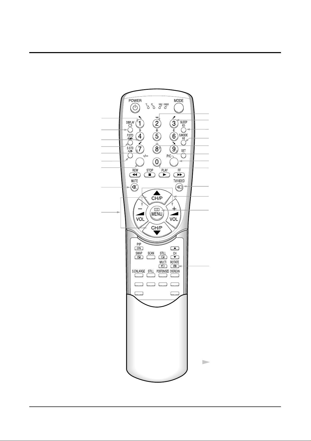
4-6 Remote Control for Servicing (Convergence Mode)
FACTORY
CONV.
ESCAPE
R/B
3SPEED
F.MENU
Factory Data Select Button
Last Data Save Button
Convergence Pattern Left Move Button
Save Button
G-Select
B-Select
B-Mute
G-Mute
Move Cursor Forward
Convergence Data
Increase, decrease button
Convergence Data Zero Button
Test/Normal
Line Shift
R-Select
Exit Button
R-Mute
Move Cursor Reverse
Convergence Picture
Move Button
Operation of remote
control may be affected
by bright artificial light
near to the TV set.
Convergence Pattern Right Move Button
Data Shift Button
(After PAL Adjustments are
Completed, Press to transmit
data to the NTSC mode)
H/V Direction Select Button
Alignment and Adjustments
Samsung Electronics 4-13
4-6-1 KEY Function
1. R-SELECT
Press to select RED color.
2. G-SELECT
Press to select GREEN color.
3. B-SELECT
Press to select BLUE color.
4. R-MUTE
Press to mute RED color.
5. G-MUTE
Press to mute GREEN color.
6. B-MUTE
Press to mute BLUE color.
7. CANCEL KEY
Press to revert to the previous data during the Convergence
Adjustment.
8. TEST/NORMAL
Press to check TV mode in the Convergence Mode.
9. LINE SHIFT
Press to move a line up/down or left/right.
10. FACTORY DATA SELECT BUTTON
Press to call the factory default values.
11. H/V DIRECTION SELECT BUTTON
Press to switch the cursor direction horizontally or vertically.
/
/
MENU
-/--

Alignment and Adjustments
4-14 Samsung Electronics
12. SAVE BUTTON
After the Convergence adjustments are completed, press to save data.
13. EXIT BUTTON
After the Convergence Adjustments are completed, press to exit to TV mode.
14. MOVE CURSOR FORWARD
Press to move the cursor right or down.
15. MOVE CURSOR REVERSE
Press to move the cursor left or up.
16. CONVERGENCE PICTURE MOVE BUTTON
17. CONVERGENCE PATTERN MOVE BUTTON
Press to move the convergence pattern left ( ) or right ( ) .
18. CONVERGENCE DATAZERO BUTTON
Press to zero the convergence correction data.
19. DATASHIFT BUTTON
Press to transmit data (PAL mode / NTSC mode).
ROTATE
Alignment and Adjustments
Samsung Electronics 4-15
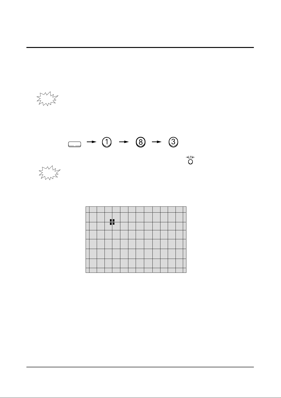
4-7 Convergence Adjustment
1. Warm up the TV for at least 30 minutes.
2. Input a PAL Signal. (Use an antenna or AV source.)
Make sure that both deflection and convergence yokes are
NOTE
3. Enter the Convergence Mode by pressing the remote control keys in the following sequence:
NOTE
properly adjusted so that the center of Green, Red, Blue pattern
is aligned on the center of screen jig.
R/B
S.STD
If OSD is displayed as shown in figure below, press the key to exit.
Then, redo step 3 to enter the Convergence Mode.
After entering the Convergence Mode, Stand by for about five seconds before
doing the adjustments.
Alignment and Adjustments
4-16 Samsung Electronics
-/--
/
4. To adjust GREEN, first press the and the keys, and then press the key.
-/--
/
5. The key moves the cursor right, and the key moves the cursor left.

Alignment and Adjustments
Samsung Electronics 4-17
The key moves the cursor horizontally or vertically.
MENU
NOTE
When the key is pressed once again, the cursor moves horizontally.
MENU
Alignment and Adjustments
4-18 Samsung Electronics
7. Use the key for overall balance.
8. After the Line Shift is cancelled by pressing the key, use the Channel
and Volume keys (Up/Down) to make big adjustments.
9. After the green convergence adjustments are completed, press the key to
save the data.

Alignment and Adjustments
Samsung Electronics 4-19
10. Superimpose the Red and Green colors by pressing the and
the keys.
11. To adjust RED, redo steps5~8.
MENU
When the cursor moves vertically
-/--
12. To superimpose the blue and green colors, press (1) the key for
/
R-Mute, (2) the key to cancel the B-Mute, and (3) the key
for B-select.
13. To adjust BLUE, redo steps 5 ~ 8, 12.
14. If any color is not properly adjusted when displaying the red, blue and
green colors, readjust the color.

Alignment and Adjustments
4-20 Samsung Electronics
15. After the color adjustments are completed, press the ( ) key to save the data.
NOTE
to the left about five seconds later.
S.STD
16. After the Convergence Adjustments are completed, press the key to exit.
The cursor moves to center, and then automatically moves up and
Alignment and Adjustments
Samsung Electronics 4-21
4-8 PC Mode
4-8-1 TV Setup Mode
Switch to External Mode
TV/External Key
SETUP MENU
TV SETUP
COMPUTER SETUP
PICTURE SETUP
EXIT
Select TV Setup
CH Down key
PC Enter
PC Enter
Switch to PC Mode
Select Key
TV SETUP MENU
H POS LEFT RIGHT
H SCALE SHRINK GROW
V POS DOWN UP
V SCALE SHRINK GROW
RECALL SETTINGS
EXIT
SAVE AND EXIT
Select TV Setup
Volume+ key
MAIN MENU
ZOOM
COMPRESS
FREEZE
SETUP
RESET
EXIT
Select menu
F.Menu Key
TV SETUP MENU
H POS L EFT RI GHT
Adjust screen left to balance
Adjust horizontal position (left)
Volume- key
TV SETUP MENU
H SCALE SHR I
Adjust screen left to balance
Adjust horizontal position (right)
Volume - key
TV SETUP MENU
V SCAL E SHRIN K GROW
Adjust screen left to balance
Adjust horizontal position (bottom)
Volume+ key
N
K
GROW
TV SETUP MENU
H POS LEFT RIGHT
H SCALE SHRINK GROW
V POS DOWN UP
V SCALE SHRINK GROW
RECALL SETTINGS
EXIT
SAVE AND EXIT
Select vertical position adjustment
CH Down key
TV SETUP M ENU
H POS LEFT RIGHT
H SCALE SHRINK GROW
V POS DOWN UP
V SCALE SHRINK GROW
RECALL SETTINGS
EXIT
SAVE AND EXI T
. Save and Exit
CH Down,Volume+ key
TV SETUP MENU
V P OS DOWN UP
Adjust screen top to balance
Adjust vertical position (top)
Volume + key
SETUP MENU
TV SETUP
COMPUTER SETUP
PICTURE SETUP
EXIT
Exit

Alignment and Adjustments
4-22 Samsung Electronics
4-8-2 Picture Setup Mode
1. Adjust four different modes:VGA3 (VGA), VGA (DOS), VESA (SVGA),
VEAS (XGA).
2). Perform the setup for each PC mode and picture setup.
SETUP MENU
TV SETUP
COMPUTER SETUP
PICTURE SETUP
EXIT
Select Picture Setup
CH Down key
PI CTURE SETUP MENU
BRIGHTNESS
COLOR SATURETION
FLICKER FILTER
VIDEO FILTER
RECALL SETTINGS
EXIT
SAVE AND EXIT
Select Picture Setup
Volume+ key
PICTURE SETUP MENU
BRI GHT NE SS
Set in the bright screen
Adjust brightness
Volume+ key
PICTURE SETUP MENU
COL OR SATURATI ON
Set in the bright screen
Adjust color saturation
CH Down, Volume+ key
SETUP MENU
TV SETUP
COMPUTER SETUP
PI CTURE SETUP
EXIT
Finish picture setup
Volume+ key
PICTURE SETUP MENU
F L I CKER F I L TE R
Set in the bright screen
Adjust flicker filter
CH Down, Volume+ key
MAIN MENU
ZOOM
COMPRESS
FREEZE
SE T UP
RESET
EXIT
Finish Computer Setup
F.Menu key
PICTURE SETUP MENU
BRIGHTNESS
COLOR SATURETION
FLICKER FILTER
VIDEO FILTER
RECALL SETTINGS
EXIT
SAVE AND EXI T
Save and Exit
CH Down, Volume- key
PC
Exit

Alignment and Adjustments
Samsung Electronics 4-23
4-8-3 Picture Setup Mode (computer setup mode only)
1. Adjust four different modes:VGA3 (VGA), VGA (DOS), VESA (SVGA),
VEAS (XGA).
2. Perform the setup for each PC mode and picture setup.
SETUP MENU
TV SETUP
COMPUT E R SE T UP
PICTURE SETUP
EXIT
Select Computer Setup
CH Down key
COMPUTER SETUP MENU
H SCAL E SHRI NK GROW
Adjust screen left to balance
Adjust horizontal position (right)
Volume+ key
COMPUTER SETUP MENU
H POS L EFT RI GHT
H SCALE SHRINK GROW
V POS DOWN UP
V SCALE SHRINK GROW
RECALL SETTINGS
EXIT
SAVE AND EXIT
Select Computer Setup
Volume+ key
COMPUTER SETUP MENU
H POS LEFT RIGHT
H SCALE SHRINK GROW
V POS DOWN UP
V SCALE SHRINK GROW
RECALL SETTINGS
EXIT
SAVE AND EXIT
Select vertical position adjustment
CH Down key
COMPUTER SETUP MENU
H POS L EFT RI GHT
Adjust screen left to balance
Adjust horizontal position (left)
Volume- key
COMPUTER SETUP MENU
V P OS DOWN UP
Adjust screen top to balance
Adjust vertical position (top)
Volume+ key
COMPUTER SETUP MENU
V SCAL E SHRIN K GROW
Adjust screen left to balance
Adjust horizontal position (bottom)
Volume+ key
COMPUTER SETUP MENU
H POS LEFT RIGHT
H SCALE SHRINK GROW
V POS DOWN UP
V SCALE SHRINK GROW
RECALL SETTINGS
EXIT
SAVE AND EXI T
Save and Exit
CH Down, Volume+ key
SETUP MENU
TV SETUP
COMPUTER SE T UP
PICTURE SETUP
EXIT
Exit

Alignment and Adjustments
4-24 Samsung Electronics
4-9 MICOM and Pins Voltage
4-9-1 Pin Layout
POW E
IR-IN
E
DVD-S
-
ED
L
STB
/
LNA -O N
LNA
PIP-MODE S/W
SCART1-IDENT
LOOP FILTER
ANALOG GND
SCART2-IDENT
ANALOG GND
ANALOG VCC
HALF TONE
OFF
-
PUT
IN
-
T
PI P-
N
PIP-L/L'
PROTECT
SCL2
SDA2
SUB-AFT
KEY1
MAIN-AFT
KEY2
OSD B
OSD G
OSD R
R
1
2
3
L
4
5
6
7
V
8
9
10
11
12
13
14
15
16
17
18
19
20
21
22
23
24
25
26
S
Z
M
|
8
0
4
M
1
D2
52
POWER2
51
BUS-STOP
50
49
MAIN-NT-V
TTX-SCL
48
D3
47
TIMER-LED
46
SECAM L/L'
45
D1
44
AMP-MUTE
43
42
SOUND-RESET
MODE-S/W
41
40
XTAL GND
VCC
39
GND
38
XTAL2
37
XTAL1
36
/RESET
35
POWER-DTTV
34
DTTV-SCL
33
TTX-SDA
32
SCL1
31
SDA1
30
VSYNC
29
HSYNC
28
BLANK
27
Alignment and Adjustments
Samsung Electronics 4-25
4-9-2 Micom Pins
1 POWER POWER ON/OFF RELAY CONTROL H--> L
2 IR IN REMOCON INPUT 4.7V
3 DVD-SEL DVD SELECTION OUTPUT 4.7V
4 STB-LED STAND-BY LED OUTPUT 4.6V
5 LNA-ON/OFF LNA CONTROL OUTPUT L
6 LNA-INPUT LNA INPUT L
7 PIP-NT-V PIP VIDEO SAW FILTER SWITCH L
8 PIP-L/L’ PIP SECAM SYSTEM SWITCH L
9 PROTECT PROTECT PORT L
10 PIP-MODE S/W PIP SECAM MODE SWITCH L
11 SCL 2 CLOCK BUS LINE 4.5V
12 SDA 2 DATA BUS LINE 4.5V
13 SCART1-IDENT SCART1 IDENT INPUT PORT L/H
14 LOOP FILTER LOOP FILTER L
15 ANALOG GND GND L
16 SUB-AFT SUB AUTO FINE TURNING CONTROL 2.3V
17 KEY 1 KEY SCAN 1 4.7V
18 MAIN-AFT MAIN TUNER AFT 2.3V
19 KEY 2 KEY SCAN 2 4.8V
20 SCART2-IDENT SCART2 IDENT INPUT PORT H
21 ANALOG GND GND L
22 ANALOG VCC VCC 5V
23 HALF TONE SIGNAL FOR OSC-FREQUENCY OSD CONTROL L
24 OSD B ON SCREEN DISPLAY BLUE OUTPUT L/H
25 OSD G ON SCREEN DISPLAY GREEN OUTPUT L/H
26 OSD R ON SCREEN DISPLAY RED OUTPUT L/H
PIN NO. ITEM FUNCTION OUT VOLT
Alignment and Adjustments
4-26 Samsung Electronics
27 BLANK OSD BLAKING SIGNAL OUTPUT L/H
28 HSYNC HORIZONTAL SYNC INPUT 4.5V
29 VSYNC VERTICAL SYNC INPUT 4.6V
30 SDA1 DATA BUS LINE 4.5V
31 SCL1 CLOCK BUS LINE 4.5V
32 TTX-SDA TELETEXT DATA BUS LINE 5V
33 DTTV-SCL DTTV CLOCK LINE L
34 POWER-DTTV DTTV POWER CONTROL L
35 /RESET HARDWARE RESET 4.8V
36 XTAL1 CRYSTAL 1 2.3V
37 XTAL2 CRYSTAL 2 2.1V
38 GND GND L
39 VCC VCC 5V
40 XTAL GND CRYSTAL GND L
41 MODE-S/W MAIN SECAM MODE SWITCH 4.6V
42 SOUND-RESET SOUND IC RESET 4.9V
43 AMP-MUTE SOUND AMP. MUTE L
44 D1 CONV. MODE CONTROL DATA1 L/H
45 SECAM L/L’ MAIN SECAM SYSTEM SWITCH H
46 TIMER-LED TIMER LED 4.6V
47 D3 CONV. MODE CONTROL DATA3 L/H
48 TTX-SCL TELETEXT CLOCK BUS LINE 5V
49 MAIN-NT-V MAIN VIDEO SAW FILTER SWITCH L
50 BUS-STOP I
2
C BUS STOP 5V
51 POWER2 PC POWER CONTROL 4.6V
52 D2 CONV. MODE CONTROL DATA2 L/H
PIN NO. ITEM FUNCTION OUT VOLT

Alignment and Adjustments
Samsung Electronics 4-27
4-9-3 PROSCAN MDL
1 DVD-Y DVD-Y INPUT 2.04V
2 GND GND GND
3 MAIN-Y/CVBS Y/CVBS INPUT 1.28V
4 MAIN-C C-INPUT 2.92V
5 GND GND GND
6 R/Pr R/Pr INPUT 2.0V
7 G/Y G/Y INPUT 2.0V
8 B/Pb B/Pb INPUT 2.0V
9 F/B FAST BLANK INPUT 0.16V
10 GND GND GND
11 HS1 1H-SYNC OUT 12 VS1 V-SYNC OUT 13 GND GND GND
14 SDA-2 SERIAL DATA LINE 2 3.0V
15 SCL-2 SERIAL CLOCK LINE 2 3.5V
16 5V-B 5V-B INPUT 5V
17 HD H-DRIVE OUT 1.6V
18 H-BLK H-BLANK INPUT 19 VD+ VERTICAL DRIVE (+VOLTAGE) 2.6V
20 VD- VERTICAL DRIVE (-VOLTAGE) 2.6V
21 ABL ABL INPUT 2.15V
22 V-BLK V-BLANK INPUT 23 EW EAST WEST OUT 2.5V
24 SC N.C 25 GND GND GND
26 SYNC V-SYNC OUT N.C
27 SYNC H-SYNC OUT N.C
28 5V-A 5V-B INPUT 29 GND GND GND
30 TEST-Y WHEN CG ADJ PATTERN INPUT -
PIN NO. ITEM FUNCTION OUT VOLT
Alignment and Adjustments
4-28
Samsung Electronics
31 DTV-Y DTV-Y INPUT 32 DTV-Pb DTV-Pb INPUT 33 DTV-Pr DTV-Pr INPUT 34 - N.C 35 - N.C 36 GND GND GND
37 OSD-R OSD-R INPUT 38 OSD-G OSD-G INPUT 39 OSD-B OSD-B INPUT 40 YS BLANK(MICOM OUT) 41 YM NOT USED 42 V-MUTE VIDEO MUTE 4.72V
43 GND GND GND
44 9V 9V 9V
45 T/P-R TTX/PIP-R 46 T/P-G TTX/PIP-G 47 T/P-B TTX/PIP-B 48 T/P-F/B TTX/PIP-F/B 49 GND GND
50 R-OUT R-OUT 51 G-OUT G-OUT 52 B-OUT B-OUT 53 GND GND GND
54 IK IK OUT 3.65V
55 SPOT SPOT OUT 56 GND GND GND
57 VM-Y VM-Y OUT 5.42V
58 - N.C -
PIN NO. ITEM FUNCTION OUT VOLT

Alignment and Adjustments
Samsung Electronics 4-29
4-9-4 PIP MODULE
1 SCL SERIAL CLOCK LINE 4.7V
2 SDA SERAL DATA LINE 4.7V
3 8V 8V INPIUT 8V
4 GND GND 0V
5 CVBS 5V-D INPUT 6 GND GND 0V
7 5V-D 5V-D INPUT 5V
8 GND GND 0V
9 PIP-AGC PIP-AGC OUTPUT 3.36V
10 PIP-MODE S/W PIP SECAM MODE SWITCH 0V
11 12V 12V INPUT 12V
12 PIP-L/L’ SECAM SYSTEM SWITCH 0V
13 PIP-NT-V PIP VIDEO SAW FILTER SWITCH 0V
14 SUB-AFT SUB-AFT OUTPUT 4.37V
15 GND GND 0V
16 IF-IN IF INPUT 17 IF-AGC N.C 18 V-SYNC V-SYNC INPUT 19 H-SYNC H-SYNC INPUT 20 F/B FAST BLANK OUTPUT 2.46V
21 GND GND 0V
22 B B OUTPUT 0.66V
23 G G OUTPUT 0.66V
24 R R OUTPUT 0.66V
PIN NO. ITEM FUNCTION OUT VOLT
 Loading...