

Page 1

5. Alignment and Adjustments
5-1 RF AGC Adjustment
1. Tune to the strongest local station.
2. Turn the AGC control fully clockwise (VR111,
on the IF board).
3. Adjust the AGC control until noise (snow)
disappears from the screen.
5-2 Screen Adjustment
1. Turn to the Active channel.
2. Adjust the VR (VR501, VR531, VR561) screen
for a normal picture is (no blooming or flyback
line).
3. Adjust the FOCUS control for well defined
scanning lines in the center area of the screen.
5-3 Horizontal Dynamic Focus
Adjustment
5-4 FBT B+Voltage Adjustment
PREPARATION
1. Note: The B+voltage adjustment (FBT) is
done during the chassis check at the factory.
Perform this adjustment after Sub-Brightness
and Convergence.
2. Warm up the TV for at least for 10 minutes.
3. Input 100% white pattern.
4. Select the “STANDARD“ video mode.
ADJUSTMENT
1. Connect the leads of a multimeter to GT405
(B+) and GT406(G).
2. Set VR401 (on deflection board) to either
126.9V (for NTSC), or 125.6V (for PAL).
PREPARATION
1. Input a crosshatch pattern.
2. Cover the Red and Blue Lenses.
3. Enter “STANDARD“ video mode.
4. Adjust the Green Lens for best focus.
ADJUSTMENT
Adjust VRZ01 (located on the convergence board).
Balance the left and right sides of the dynamic
focus lines.
Fig. 5-1 Balance the left and right sides
5-1Samsung Electronics
Page 2
Alignment and Adjustments
5-5 Lens Focus and Static Focus
Adjustment
5-5-1 Static Focus (Electric Focus)
PREPARATION
1. Select the “STANDARD“ video mode.
2. Input a crosshatch pattern.
3. Cover the lenses that are not being adjusted.
4. Connect a convergence jig and read data.
5. Adjust the lens for best focus.
ADJUSTMENT
Vary the focus pack VR (Red, Blue) on the front
cabinet. Adjust the TV for best possible focus
around the center of the crosshatch pattern,
without losing overall screen balance.
5-5-2 Lens Focus
PREPARATION
1. Do this adjustment after the static focus
adjustment .
2. Select the “ STANDARD“ video mode.
(Contrast: 64, Brightness: 32)
3. Input a cross hatch pattern.
ADJUSTMENT
1. Loosen the lens screws.
2. Cover the two lenses that are not being
adjusted.
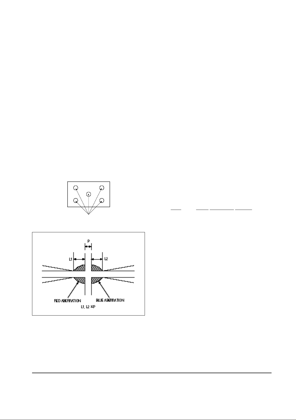
3. Adjust the lens, observing the color aberration
vertically and horizontally within 3 blocks of
the center of the crosshatch pattern.
4. When the lens is turned clockwise, the color
aberration will change as follows:
Fig. 5-2 Crosshatch Pattern. Examine these points together
Fig. 5-3 Color Aberration
Lens Color Aberration Change
R Orange —- Crimson
G Blue —- Red
B Purple —- Green
5. Green lens adjustment:
Set the lens at the point where Blue just
changes to Red. If the color aberration is
irregular throughout the picture screen,
adjust the lens to show Red within a 3-block
grid around the horizontal center-line.
Observe the the color aberration near the
intersection points of the horizontal and
vertical lines (approximately 1 - 3 mm area).
If the aberration is irregular, adjust the lens as
shown in the diagram below. (Accurate
alignment of Green is important for overall
color quality.)
6. Set the Red lens at the point where Orange
becomes Crimson.
7. Set the Blue lens at the point where Purple
becomes Green.
5-2 Samsung Electronics
Page 3

5-6 Convergence Adjustment
5-6-1 Convergence Adjustment
Alignment and Adjustments
1. Input a PAL pattern.
2. Warm up the set for 30 minutes before
adjustment.
3. Display the test pattern (Crosshatch) by
pressing the remote-control keys in this
sequence : Conv.°Ê Mute °Ê 1°Ê 8°Ê 2.
4. When the convergence data is severely tilted
(or if readjustments are necessary because the
convergence module was replaced), select the
"Mute" and "Yellow (TTX)" keys in turn so that
the basic data of module micom applies to the
convergence adjustments.
When making only one convergence
adjustment, only one parameter needs to be
adjusted. (The basic data does not change.)
5. After selecting R-Mute and B-Mute, display
only a green color pattern. Center the pattern
by adjusting CY.
6. After selecting G-Mute and B-Mute, adjust the
Red CY to center the picture.
7. Center the Blue Pattern as above.
11. Adjust Blue as above.
12. After the adjustments are completed, press
"Recall" to save the data.
13. Change from PAL mode to NTSC when
making NTSC adjustments.
14. After setting the NTSC line (on Screen Jig),
readjust as 7~10.
15. After the NTSC pattern adjustments are
completed, press the " RECALL" key to save
the NTSC data.
16. After the Convergence Adjustments are
completed, press the Escape key.
Note
1. If the convergence data is lost during
adjustment, use the"Saturation" (TV/Video)
key to reset the data to the initial values of the
ROM.
2. Make minor adjustments with the User
Convergence key.
A "+" pattern appears when "Conv." is pressed.
8. After the picture is centered, begin the
convergence adjustments.
First, display the green pattern:
The "Menu" key moves the cursor vertically
and horizontally.
Use the Channel and Volume keys
( Up/Down) to adjust convergence.
9. Use the "Surround" key for minor adjustments.
10. After the Green Adjustment is completed,
press the R-Mute key (confirm Green to Red).
Samsung Electronics
3. Use the "R/B" and "Ch/Vol" keys to correct
convergence. After the adjustments are
completed, press "Escape".
5-3
Page 4

Alignment and Adjustments
5-6-2 Screen Jig
Fig. 5-5 43 inch JIG Screen
5-4 Samsung Electronics
Page 5

Alignment and Adjustments
Samsung Electronics
Fig. 5-5 52 inch JIG Screen
5-5
Page 6

Alignment and Adjustments
5-6-3 Remote Control for Servicing
5-6 Samsung Electronics
Page 7

5-7 Manual Alignment (Factory Mode)
1. Enter the Factory Mode. Press the remote-control keys in this sequence:
Alignment and Adjustments
PICTURE OFF
2. Use the CHANNEL and VOLUME keys (Up/Down) to move the cursor. Select
an alignment parameter:
SERVICE MODE
ADJUSTMENT
TEST PATTERN
OPTION BYTES
RESET
BONUS
3. Adjustment must be done for both 50Hz and 60Hz field rates:
SBT 08 GG 49
SCR 10 BG 32
SCT 13 PW 32
STT 08 GAM 00
RRC 26 ALS 07
GRC 42 ASS 32
BRC 32 PCT 04
RG 28 PTT 32
¢°
Adjustment I
SLEEP
¢°
P.STD
Function
SUB-BRIGHT
SUB-COLOR
SUB-CONTRAST
SUB-TINT
RED REFERENCE
¢°
MUTE
¢°
Table 5-1
OSD
SBT
SCR
SCT
STT
RRC
Range
00~13
00~13
00~13
00~13
00~63
PICTURE ON
Note
Low-light adjustment
Samsung Electronics
GREEN REFERENCE
BLUE REFERENCE
RED GAIN
GREEN GAIN
BLUE GAIN
PEAK WHITE
GAMMA
AUDIO LEVEL SETTING
AUDIO SEPARATION SETTING
PIP CONTRAST
PIP TINT
GRC
BRC
RG
GG
BG
PW
GAM
ALS
ASS
PCT
PTT
00~63
00~63
00~63
00~63
00~63
00~63
00~63
00~15
00~63
00~15
00~63
"
"
High-light adjustment
"
"
5-7
Page 8

Alignment and Adjustments
4. Access Adjustment II by pressing the CHANNEL keys (Up/Down) while the cursor is positioned
on "SBT" or "PTT" (see Adjustment I):
PHS 42 PVA 15
PEW 27 PSC 30
PEP 23 PVS 10
PEC 02 HSP 13
PET 47 PVP 10
PSC 40 PHP 72
Adjustment II - 50Hz Picture
Table 5-2
Function
PAL HORIZONTAL SHIFT
NTSC HORIZONTAL SHIFT
PAL E-W WIDTH
NTSC E-W WIDTH
PAL E-W PARABOLA
NTSC E-W PARABOLA
OSD
PHS
NHS
PEW
NEW
PEP
NEP
Range
00~63
00~63
00~63
00~63
00~63
00~63
NHS 32 NVA 32
NEW 27 NSC 13
NEP 30 NVS 55
NEC 02 HSN 11
NET 28 NVP 04
NSL 16 NHP 73
Adjustment II - 60Hz Picture
Table 5-2 (Continued)
Function
PAL VERTICAL SHIFT
NTSC VERTICAL SHIFT
PIP PAL HORIZONTAL SHIFT
PIP NTSC HORIZONTAL SHIFT
PIP PAL VERTICAL POSITION
PIP NTSC VERTICAL POSITION
OSD
PVS
NVS
HSP
HSN
PVP
PVN
Range
00~63
00~63
05~20
00~20
00~33
00~33
PAL E-W TRAPEZIUM
NTSC E-W TRAPEZIUM
PAL VERTICAL SLOPE
NTSC VERTICAL SLOPE
PAL VERTICAL AMPLITUDE
NTSC VERTICAL AMPLITUDE
PAL S CORRECTION
NTSC S CORRECTION
PET
NET
PSL
NSL
PVA
NVA
PSC
NSC
00~63
00~63
00~63
00~63
00~63
00~63
00~63
00~63
PIP PAL HORIZONTAL
POSITION
PIP NTSC HORIZONTAL
POSITION
PHP
PHN
00~83
00~83
5-8 Samsung Electronics
Page 9

Alignment and Adjustments
5. After the Factory Mode Adjustments are completed, return to the first menu and set up "Test Pattern,"
"Option" and "Bonus." Use the CHANNEL and VOLUME keys to position the cursor and make a
selection:
7-Color Bar
Cross hatch
Red
Green
Blue
Test Pattern I
OE 80
BON 01
WD 08
01 40
02 32
03 10
AMS 00
SVR 00
Bonus (see data, below)
Kara-OK On
TTX On
Tuner CCIR
List
OSD Language Select
Option Bytes
Table 5-3
Content
TDA4780 BLACK STRETCH
TDA9170 BLACK OFFSET COMPENSATION ENABLE
TDA9170 WINDOW SELECT
USER VARIABLE GAMMA (TDA9170)
ADAPTIVE GAMMA (TDA9170)
NON LINEARITY AMPLITUDE (TDA9170)
AMPLITUDE SELECTION (TDA9170)
FULL SCREEN BLACK LEVEL (TDA9170)
OSD
OE
BON
WD
01
02
03
AMS
SVR
Samsung Electronics
5-9
Page 10

5-10 Samsung Electronics
 Loading...