

Samsung SP0612N, SP1203N, SP0802N, SP1214N, SP0401N Service Manual
...
Model:
1. Specification summary
2. Block Diagram of HDD
3. Connector & Jumper Pin Assignments
4. How to check if HDD is working
5. Exploded View
6. Maintenance Cylinder Configuration
7. How to use HUTIL Program
8. How to progress Burn-In Test
9. Caution
Attachment
1. The basic information
related HDD
Attachment
2. HDD related terms
Attachment
3. Q&A
Contents
Hard Disk Drive
HARD DISK DRIVE service
manual
PALO(P80)Series
SP0211N
SP0311N
SP0401N
SP0412N
SP0612N
SP0802N
SP1203N
SP1214N
SP1604N
SP0231N
SP0421N
SP0422N
SP0622N
SP0812N
SP1213N
SP1224N
SP1614N
PALO
1
SAMSUNG HARD DISK DRIVE
1. Specification Summary
Items Specification Remarks
Voltage Requirement DC +12V/±10%, DC +5V/±5%
Interface ATA - 6
Capacity
SP02X1N - 20.0GB (1CH)
SP03X1N - 30.0GB (1CH)
SP04X1N - 40.0GB (1CH)
SP04X2N - 40.0GB (2CH)
SP06X2N - 60.0GB (2CH)
SP08X2N - 80.0GB (2CH)
SP12X3N - 120.0GB (3CH)
SP12X4N - 120.0GB (4CH)
SP16X4H - 160.0GB (4CH)
UDMA133supporting
Disk / Head
SP02X1N - 20.0GB (1DISK)
SP03X1N - 30.0GB (1DISK)
SP04X1N - 40.0GB (1DISK)
SP04X2N - 40.0GB (1DISK)
SP06X2N - 60.0GB (1DISK)
SP08X2N - 80.0GB (1DISK)
SP12X3N - 120.0GB (2DISK)
SP12X4N - 120.0GB (2DISK)
SP16X4H - 160.0GB (2DISK)
Features
S.M.A.R.T Compliant
Buffer size 2 Mbytes
MTBF(POH) 500,000 hours
Seek Time
(RD/WT typical)
TracktoTrack:0.8/1.0ms
Average : 8.9 / 10 ms
Full Stroke : 18 / 19 ms
RPM 7200±0.35 % RPM
Temperature(Operating) 0~60°C
Humidity(Operating) 5~90%
Non-condensing
Temperature(Non-operating) 63 G @2.0ms
Humidity(Non-operating) -40~+70°C
Linear Shock
(Operating)
5~95% Linear Shock
Linear Shock
(Non-operating)
350 G (2ms linear shock)
PALO
3
SAMSUNG HARD DISK DRIVE
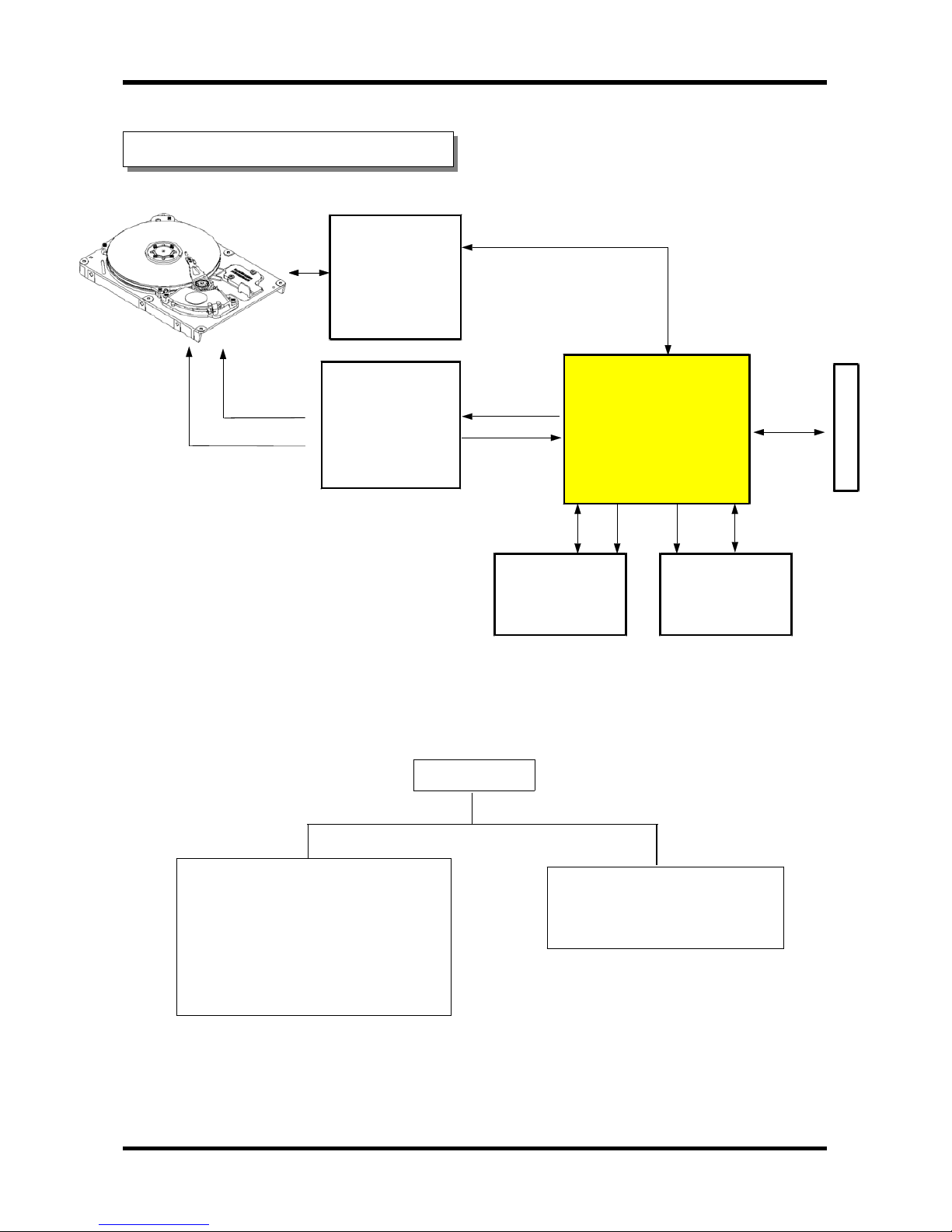
2. Block Diagram of HDD
HDD
PCBA (PCB ASSEMBLY)
-PCBA
HDA (HEAD DISK ASSEMBLY)
-HEAD
-DISK
- VCM (Voice Coil Motor)
- SPM (Spindle Motor)
PREAMP &
WRITE DRIVER
Marvell
81G5114
SPINDLE MOTOR &
ACTUATOR COMBO
DRIVER
HA13627
AT Controller
R/W Channel
Servo Controller
Dual-DSP
88I5520
Buffer 64Mbit
EM638165
A
T
A
B
U
S
HDA
Flash 1Mbit
M29F102B
PALO
4
SAMSUNG HARD DISK DRIVE
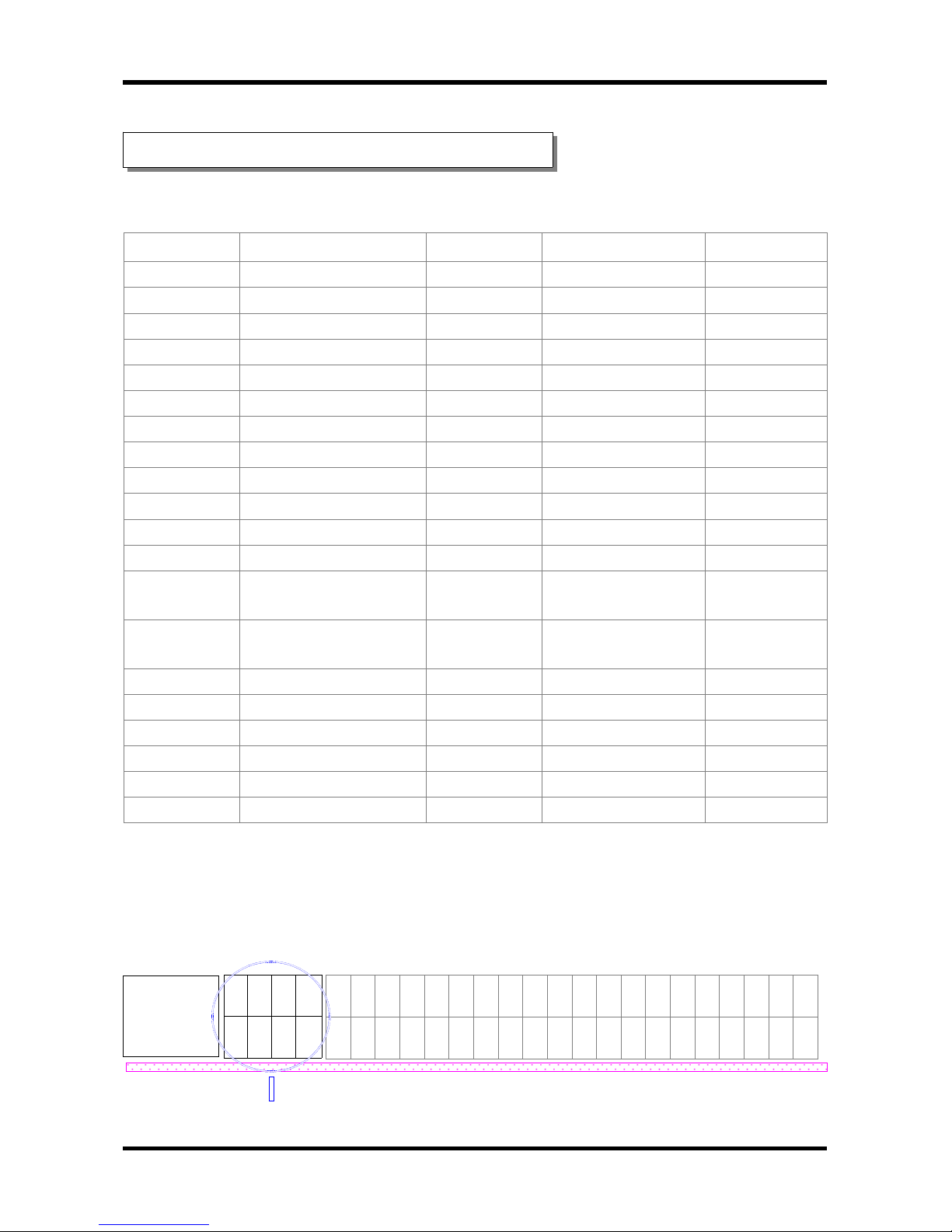
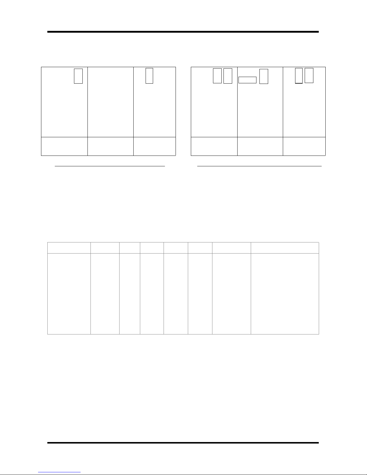
3. Connector / Jumper Pin Assignment
●
40 Pin I/O Connector Interface Signals
Number Signal Number Signal Remarks
1 RESET- 2 GND
3 DD7 4 DD8
5 DD6 6 DB9
7 DD5 8 DB10
9 DD4 10 DB11
11 DD3 12 DB12
13 DD2 14 DB13
15 DD1 16 DB14
17 DD0 18 DB15
19 GND 20 Key Pin
21 DMARQ 22 GND
23 DIOW-:STOP 24 GND
25 DIOR - : HDMARDY
: HSTROBE
26 GND
27 IORDY : DDMARDY
:HSTROBE
28 CSEL
29 DMACK 30 GND
31 INTRQ 32 IOCS16
33 DA1 34 PDIAG - : CBLID 35 DA0 36 DA2
37 CS0- 38 CS139 DASP- 40 GND
2 4 6 8 10 12 14 16 18 20 22 24 26 28 30 32 34 36 38 40
1 3 5 7 9 11 13 15 17 19 21 23 25 27 29 31 33 35 37 39
oooo
+GG+
12NN5
VDDV
2 4 6 8
1 3 5 7
JUMPER PIN
●
Jumper Pin Assignment
PCBA components side
HDA BASE
PALO
5
SAMSUNG HARD DISK DRIVE
Model CYL HD PRE LZ SEC SIZE Remarks(LBA)
SP02X1N
SP03X1N
SP04X1N
SP04X2N
SP06X2N
SP08X2N
SP12X3N
SP12X4N
SP16X4H
38,869
58,246
77,622
77,622
116,374
155,127
232,632
232,632
310,137
16
16
16
16
16
16
16
16
16
X
X
X
X
X
X
X
X
X
X
X
X
X
X
X
X
X
X
63
63
63
63
63
63
63
63
63
20.0 GB
30.06 GB
40.0 GB
40.0 GB
60.0 GB
80.0 GB
120.0 GB
120.0 GB
160.0 GB
39,179,952
58,711,968
78,242,976
78,242,976
117,304,992
156,368,016
234,493,056
234,493,056
312,618,096
●
BIOS Setup Parameter
②④⑥⑧
①③⑤⑦
②④⑥⑧
①③⑤⑦
②④⑥⑧
①③⑤⑦
MASTER
(1DRIVE)
SLAVE
CABLE
SELECT
M
A
S
T
E
R
32
G
C
L
I
P
C
S
E
L
S
T
M
A
S
T
E
R
32
G
C
L
I
P
C
S
E
L
S
T
M
A
S
T
E
R
32
G
C
L
I
P
C
S
E
L
S
T
< Setting for No Capacity Limit>
②④⑥⑧
①③⑤⑦
②④⑥⑧
①③⑤⑦
②④⑥⑧
①③⑤⑦
MASTER
(1DRIVE)
SLAVE
CABLE
SELECT
M
A
S
T
E
R
S
L
A
V
E
C
S
E
L
S
T
M
A
S
T
E
R
32
G
C
L
I
P
C
S
E
L
S
T
M
A
S
T
E
R
32
G
C
L
I
P
C
S
E
L
S
T
< 32GB Capacity Limit of PC/BIOS >
PALO
6
SAMSUNG HARD DISK DRIVE
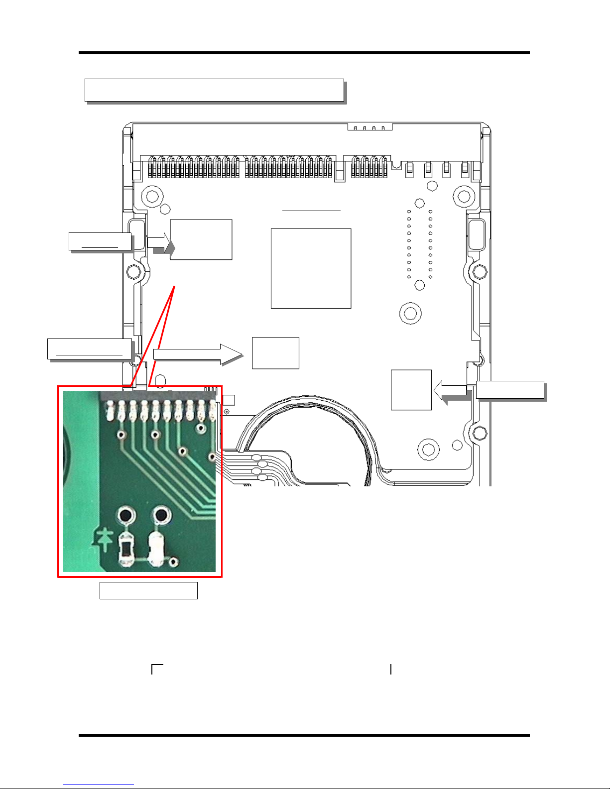
4. How to check if HDD is working.
※
How to check if your HDD is working
※
1) Insert LED to LED Hole of PCBA shown above and check HDD alive.
①
Insert LED to LDD1,LDD2 of PCBA LED Hole.
②
Insert LED as follows: LDD1⇒+ , LDD2
⇒―
③
Insert "
" part within LED to the―(LDD2) direction and " " part to the +(LDD1) direction.
2)YoucancheckifHDDisworkingbyseeingtheLEDonPCcase.
Controller
DRAM
Combo IC
Spindle Motor
LED Hole
LED
Flash ROM
PALO
7
SAMSUNG HARD DISK DRIVE
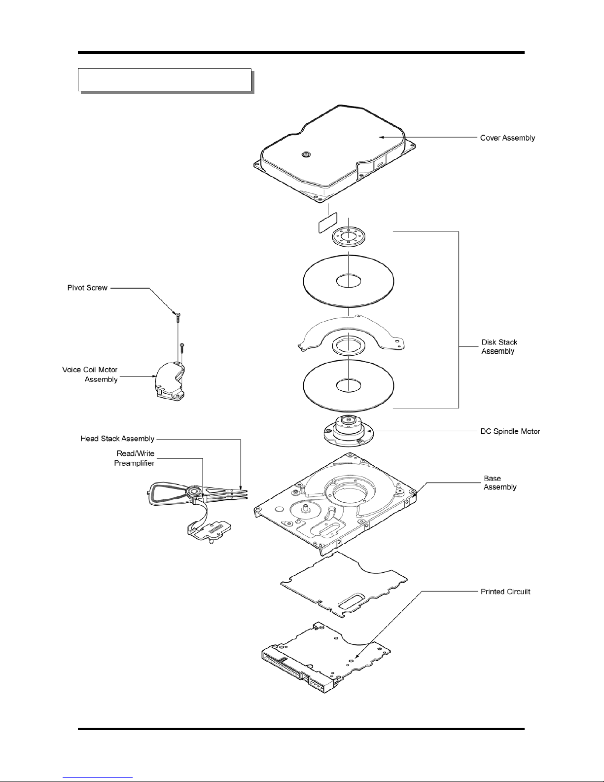
5. Exploded View

PALO
8
SAMSUNG HARD DISK DRIVE
<< Major components of HDD >>
HDD is formed by major components as follows: Base, Cover, ARM(E-Block), Latch, Crash Stop,
Pivot Bearing, Breather Filter, Window Clock, Window Push Pin, Jump Pin, Spindle Motor,
Disk-damper, Magnetic Head, Magnetic Disk, PCBA
①
Base
Base could be a basic frames for HDD assembly. Spindle motor, ARM, VCM, cover and PCBA
are assembled on it, and other components are sub-assembled on those configuration.
ARM and Spindle motor assembled to Head and Disk each in advance,then those are assembled
on Base. If base could be effected by external and internal vibration (spindle motor
& actuator's fake vibration), relative displacement occurred between head and disk so to
reduce this effect to PES(Position Error Signal) and data signal, shape design concerned
mode shaping should be needed.
②
Cover
Cover protect HDD components from the exterior impact and play role of sealing to cut off
particle and moisture which could be a fatal factor to head and disk. Cover is also designed
in consideration of noise and vibration effect.
③
ARM (E-block)
ARM is assembled HGA and VCM coil back and forth and it is connected to pivot axis pivot
bearing. When VCM coil generate torque due to electromagnetic force of VCM, ARM swing around
pivot and play a role of carriage so as head may access to information side of disk.
Inertia: It is the best w ay to shorten data access time that shows how fast head can
reach to the proper point on of HDD efficiency, is minimizing ARM's weight to decrease inertia.
And then to decrease weight of ARM, it'll be composed low density materials and reduce ARM's
size within safety allowed when designed.
Unbalance: If the center of gravity for ARM isn't the same with that of pivot center,
unbalance occur and it caused ARM to torque.
And acceleration might affect on unbalance mass in condition impact or vibration are given
from the exterior. In case of magnetic latch, this unbalance could be a reason that latch
released. Therefore shape simulation of ARM should be designed lest the center of gravity
should go off center of revolving.
④
Latch
When power HDD off, spindle motor stop spinning and park at parking zone automatically
according to the order systemized. By that time if head is given any impact or vibration
from the exterior, head invade data zone clung to disk. And then data damaged consequently,
Latch solve the problem above as maintain the regular distance of ARM.

PALO
9
SAMSUNG HARD DISK DRIVE
⑤
Crash Stop
Crash stop is made of elastic material and weaken a impact of actuator in emergency condition,
head getting out of data zone when it move to parking zone or seek.
⑥
Pivot Bearing
Pivot bearing is a roll bearing fixed the center of gyration of ARM. Inner Race is fixed by
screw after being connected to Base pivot and outer Race is fixed by retaining ring after
being connected by ARM's hole and make the ARM's revolving movement actively.
⑦
Breather Filter
In the interior of HDD, air flow is formed by the spinning disk in high speed and pressure
distribution occurred. This pressure is lower than atmospheric pressure of the exterior of
HDD and due to this, the outside air inflow into the interior caused contamination.
Breather filter fixed in inflow plug induce clean air and help air circulation.
⑧
Window Clock
Head must know the data's location information to access data on disk. Servo write is
a process of recording information disk. To record information, we make hole that head
for servo write can enter the interior of HDD and this hole is window clock.
This hole is closed with sealing label after done servo writing, be careful not to be
occurred inner contamination due to label's injury.
⑨
Window Push Pin
Head should be controlled to move on disk at a regular track pitch interval rate during
servo writing. ARM is torqued by VCM continuously and was controlled each track's moving
using push pin. Window push pin is a hole for this, the pin could enter interior of HDA
and be careful contamination caused by label's injury because this hole is closed by sealing
label after done servo writing.
⑩
Jump Pin
During installing, HDD need setting of pin organization in the next according to
the drive running mode: master drive in single system, master drive in dual system,
slave drive in dual system.
⑪
Spindle Motor (FDBM : Fluid Dynamic Bearing Motor)
Spindle motor is a sort of small motor which can change electric energy to mechanical energy
utilizing for magnetic field. When the current of stator's coil formed by electromagnet
is on, magnetic power occur between stator and rotator. (repeal occur between same pole and
attract occur in case of different pole) This power can make rotator revolve and we should
keep on changing the magnetic pole of the stator to maintain rotate at regular speed.
To progress this function, we deduct rotation speed and circuit for controlling needed.
It is possible to control the current flow and time interval with Hall element and MR
PALO
10
SAMSUNG HARD DISK DRIVE
element (these are sensitive to voltage change). The magnetic disk of hard disk is running
by DC Brushless direct drive motor directly. Brush has long life and high reliability
because it doesn't have belt. Recently we use flat motor to be adopted to the request of
minimizing. Spindle motor rotate a disk media at regular speed.This device start to rotate as
soon as put power on and no matter what HDD read or write data,spindle motor always revolve.
Besides accurate reading from the media point of view is possible when maintain the constant
speed within 0.1%,rotation error. The control circuit of spindle motor receive the index data
from the spindle motor or media at every spin and check whether constant speed persists or not
then revise the speed. Spindle motor is applied to DC brushless motor.
⑫
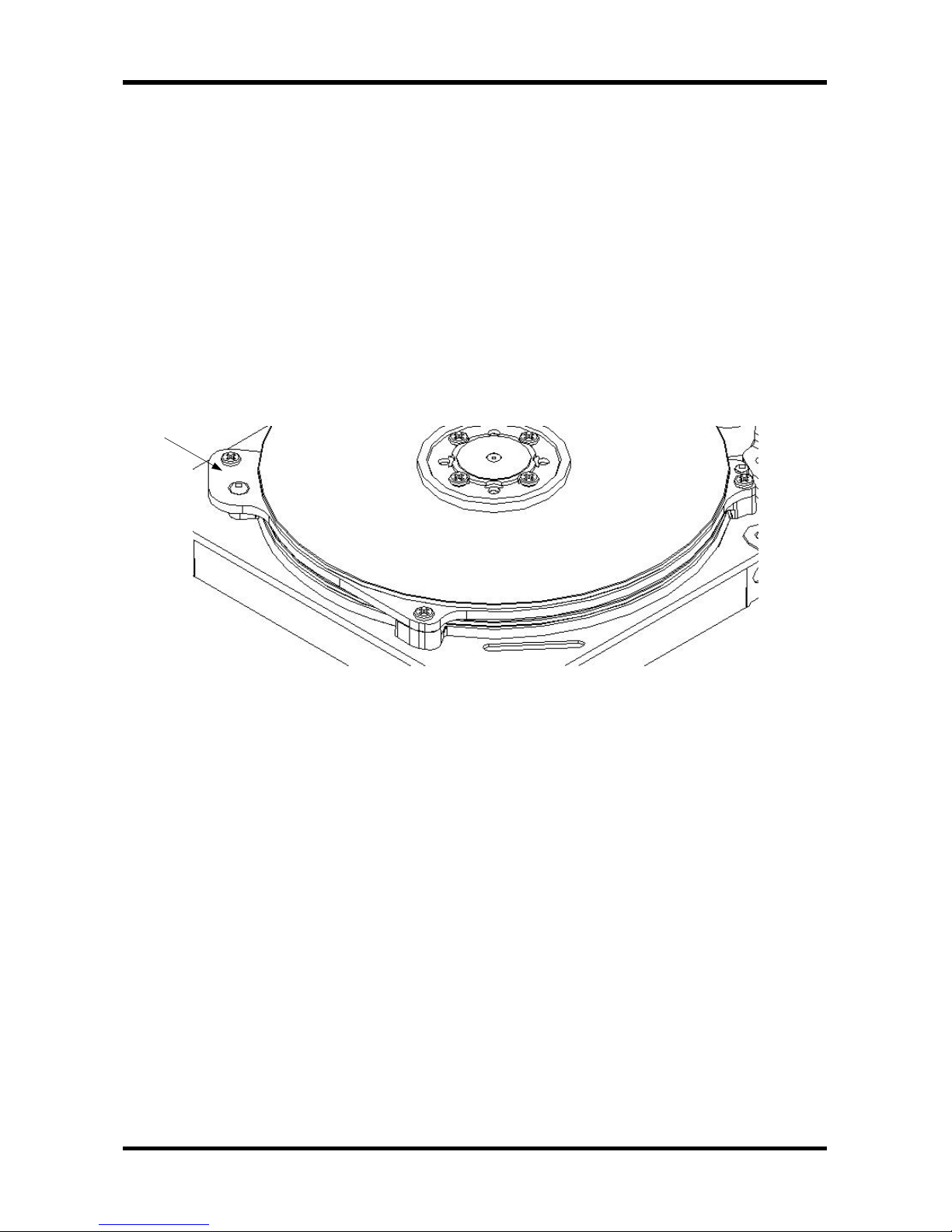
Disk-Damper
PALO(P80) series use Disk-damper for PES and acoustic noise. Disk-damper is located between
upper disk and bottom disk. Disk-damper reduce disk fluttering and acoustic noise by
air damping.
⑬
Magnetic Head
Magnetic field is formed around the conduct on passing electric current to conductor and
the direction and size of magnetic field are decided by those of an electric current.
Magnetic head build a minute gap in core (formed by ring) and pass an electric current then
strong magnetic leakage are occurred around gap thus magnetic particles of media vary the
direction according to the that of current: this is called recording. On the contrary, a
process induce magnetic signal to electric signal is called reading(decipherment).
⑭
Magnetic Disk
Recording carrier become a permanent magnet according to applying magnetic material to the
surface and change the magnetization direction of a electromagnet and it is possible to
store information during long term.
⑮
PCBA
PCBA is a circuit element concerning about HDD running and constructed in
engine IC,COMBO IC,read/write IC,ROM ,and sort of chip etc.
- Engine IC: contained RAM&Interface IC and exchange information to computer.
- COMBO IC: Controlling spindle motor & VCM running when HDD power on.
- Read/Write IC: read/write of HDD
- ROM: Checking HDD basic function and management basic spec.
Disk-Damper
PALO
11
SAMSUNG HARD DISK DRIVE
6. Maintenance Cylinder Configuration
File Name Size Cyl Sector Ref ID Descriptions
FSI 1 0 1 File System Information record
FSI2 Backup copy of FSI
FIT 4 0 2 File Information Table
FIT2 Backup copy of FIT
MLIST 1 0 6 M_LIST Maintenance Cylinder Defect List
SV_TBL 3 0 7 SVOTBL Servo Table
CONFIG 2 1 1 CONFIG System Configuration Data
SERIALNO 2 1 3 SERNUM Serial Number
BI_SCRPT 4 1 5 BISCRT Burn-In Script
BI_RESLT 1 1 10 BIRSLT Burn-In Result
BI_CRTRA 1 1 11 CRITER Burn-In Criteria
FNL_TEST 8 1 12 FNLTST Final Test
CHN_TBL 8 1 30 CHTBL0 Channel Table
GEO_TBL 32 1 46 GEOTBL Drive Geometry Table
VLIST_H 1 1 78 VLSTHD Servo Defect List header
VLIST 16 1 79 V_LIST Servo Defect List
SLIST_H 1 1 111 SLSTHD Slip Sector List Header
SLIST 128 1 112 S_LIST Slip sector list
TLIST 2 1 368 T_LIST Track Defect List
RLIST 6 1 372 R_LIST Reassign List
TMPRTURE 1 1 380 TMPREC Temperature Measurement Data
SET_MAX 1 1 381 SETMAX Set max LBA number
SECURITY 1 1 382 SECUTY Security data
SV_TBL2 3 1 383 SVBKUP Servo table backup
CHN_TB2 8 1 386 CHTBL1 Channel table backup
OVERLAY 400 1 401 OVRLAY Overlay firmware code
BI_TIME 1 4 55 BITIME Burn-In test time
ER_CNT 1 4 59 ERRCNT Burn-in error count
SV_ERCNT 1 4 60 SVECNT Burn-in servo error count
SCN_GRAY 1 4 61 SCNGRY Scan gray data
PAR_MON 10 4 62 PARMON Burn-in channel parameter monitor
WK_HEAD 10 4 72 WKHEAD Weak head data
TPI_WRW 4 4 82 TPIWRW Burnin TPI measurement data
MR_TUNE 5 4 86 MRTUNE MR head tune data
DLIST 256 4 91 D_LIST Primary defect list
TST_GEO 84 4 347 TSTGEO Geometry table for test/select TPI/BPI
TST_ZH 64 4 431 TST_ZH Channel table for BPI test
GEO_ZH 16 4 495 GEO_ZH BPI test results
AZL_BPI 1 4 521 ADTBPI
SMRT 8 11 1 SMRTBL Smart data
SMRT_LOG 4 11 2 SMRTLG Smart log
SMRT_WTS 5 11 9 SMRTWT Smart write test
SMRT_HLG 512 11 14 SMTHLG Smarthostlog
BIAS_SHK 200 11 526 BIASHK Bias shock data
END-FIT End of Record
 Loading...