

Page 1
Ed. 00
SMT-R2000
User s Manual
Page 2

COPYRIGHT
This manual is proprietary to SAMSUNG Electronics Co., Ltd. and is protected by copyright.
No information contained here in may be copied, translated, transcribed or duplicated for any commercial
purposes or disclosed to the third party in any form without the prior written consent of SAMSUNG Electronics
Co., Ltd.
TRADEMARKS
Product names mentioned in this manual may be trademarks and/or registered trademarks of their respective
companies.
This manual should be read and used as a guideline for properly installing and operating the product.
This manual may be changed for the system improvement, standardization and other technical reasons without prior
notice.
If you need updated manuals or have any question s concerning the contents of the manuals , contact our Document
Center at the following address or Web site:
Address: Document Center 18th Floor IT Center. Dong-Suwon P.O. Box 105, 416, Ma etan-3dong Yeongtong-gu,
Homepage: http://www.samsungdoc s.com
©2005 SAMSUNG Electronics Co., Ltd. All rights reserved.
Suwon-si, Gyeonggi -do, Korea 442 -600
Page 3

INTRODUCTION
Purpose
This manual introduces Access Point(AP)/Repeater SMT-R2000, and describes how to
assemble/disassemble SMT-R2000 and troubleshoot when any failue occurs. In addition,
this document describes its hardware configuration and circuits and provides the parts list
for SMT-2000.
SMT-R2000 Service Manual
Document Content and Organization
This manual consists of five Chapters and two Appendices.
CHAPTER 1. introduction of SMT-R2000
Introduces SMT-R2000 and describes the configuration and specifications of SMT-R2000.
CHAPTER 2. Assembly and Disassembly describes;
How to assemble/disassemble SMT-R2000.
CHAPTER 3. Troubleshooting describes;
How to troubleshoot when any failure occurs while operating SMT-R2000.
© SAMSUNG Electronics Co., Ltd. I
Page 4
INTRODUCTION
Conventions
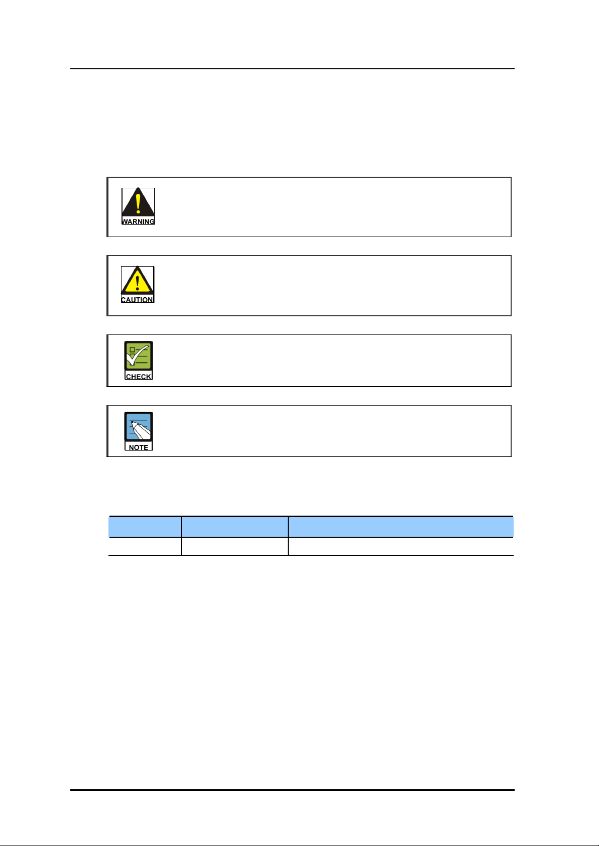
The following types of paragraphs contain special information that must be carefully read
and thorough ly understood. Such information may or may not be enclosed in a rectangular
box, separating it from the main text , but is always preceded by an icon and/or a bold title.
WARNING
Provides information or instructions that the reader should follow in order to avoid
CAUTION
Provides information or instructions that the reader should follow in order to avoid
personal injury or fatality.
a service failure or damage to the system.
CHECKPOINT
Provides the operator with checkpoints for stable system operation.
NOTE
Indicates additional information as a reference.
Revision History
EDITION DATE OF ISSUE REMARKS
00 12. 2005. Original Draft
II © SAMSUNG Electronics Co., Ltd.
Page 5
SMT-R2000 Service Manual
FCC CONCERNS
FCC Compliance Statement
This equipment has been tested and found to comply with the limits for a Class B digital device, pursuant
to part 15 of the FCC Rules. These limits are designed to provide reasonable protection against harmful
interference in a residential installation.
This equipment generates, uses and can radiate radio frequency energy and, if not installed and used in
accordance with the instructions, may cause harmful interference to radio communications. However, there is
no guarantee that interference will not occur in a particular installation. If this equipment does cause
harmful interference to radio or television reception, which can be determined by turning the equipment off
and on, the user is encouraged to try to correct the interference by one or more of the following measures:
- Reorient or relocate the receiving antenna.
- Increase the separation between the equipment and receiver.
- Connect the equipment into an outlet on a circuit different from that to which the receiver
is connected.
- Consult the dealer or an experienced radio/TV technician for help.
RF Exposure Statement:
The antenna(s) used for this device must be installed to provide a separation distance of at
least 20 cm from all persons and must not be co-located or operating in conjunction with
any other antenna or transmitter.
RF Exposure Statement:
This device is restricted to indoor use only within the 5.15-5.25 GHz band to reduce any
potential for harmful interference to co-channel MSS operations.
Do not
Any changes or modifications to the equipment not expressly approved by the
party responsible for compliance could void user’s authority to operate the
equipment.
© SAMSUNG Electronics Co., Ltd. III
Page 6
SAFETY CONCERNS
For product safety and correct operation, the following information must be given to the
operator/user and shall be read before the installation and operation.
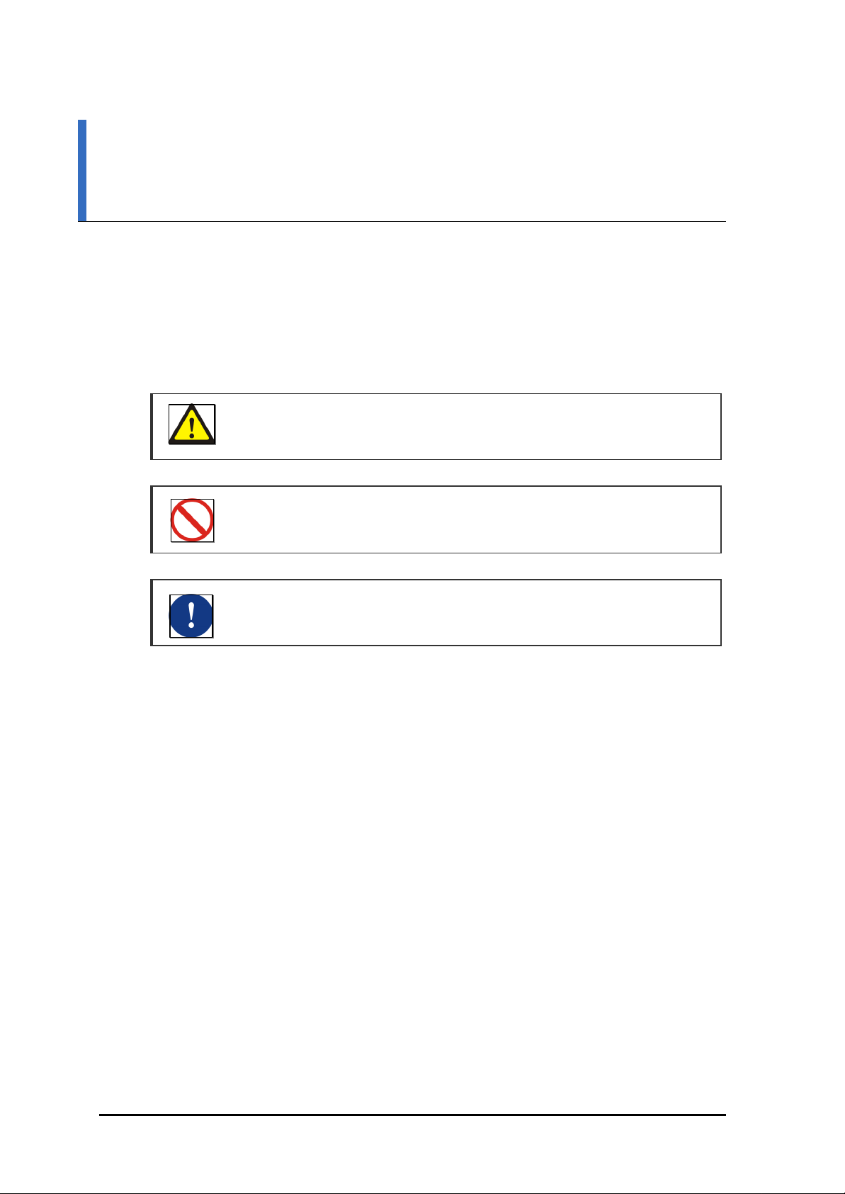
Symbols
Caution
Indication of a general caution
SMT-R2000 Service Manual
Restriction
Indication for prohibiting an action for a product
Instruction
Indication for commanding a specifically required action
© SAMSUNG Electronics Co., Ltd. IV
Page 7
SMT-R2000 Service Manual
CAUTION
Caution
When Removes Shield Can
When removes Shiel ded Can, be careful of the damage of RF terminal parts
caused by heat.
© SAMSUNG Electronics Co., Ltd. V
Page 8

SMT-R2000 Service Manual
TABLE OF CONTENTS
INTRODUCTION I
Purpose.........................................................................................................................................................I
Document Content and Organization.........................................................................................................I
Conventions.................................................................................................................................................II
Revision History ...........................................................................................................................................II
FCC/SAFETY CONCER NS IV
Symbols ......................................................................................................................................................IV
Caution.........................................................................................................................................................V
CHAPTER 1. Introduction of SMT-R2000 1-1
1.1 SMT-R2000 Overview..........................................................................................................................1-1
1.2 SMT-R2000 Configuration .................................................................................................................1-2
1.2.1 Front Panel of SMT-R2000.......................................................................................................1-2
1.2.2 Rear Panel of SMT-R2000.......................................................................................................1-3
1.3 Hardware Specification......................................................................................................................1-4
CHAPTER 2. Assembly and Disassembly 2-1
2.1 Configuration of SMT -2100C Main Board......................................................................................2-1
2.2 Disassembling......................................................................................................................................2-2
2.3 Assembling ...........................................................................................................................................2-5
CHAPTER 3. Troubleshooting 3-1
3.1 LED Failure ............................................................................................................................................3-2
3.2 Power Failure........................................................................................................................................3-3
3.3 Wireless Failure -5 GHz......................................................................................................................3-4
3.4 Wireless Failure -2.4 GHz ..................................................................................................................3-5
3.5 Network Connection Failure.............................................................................................................3-6
© SAMSUNG Electronics Co., Ltd. VI
Page 9

SMT-R2000 Service Manual
LIST OF FIGURES
Figure 1.1 Front Panel of SMT-R2000 .............................................................................................. 1-2
Figure 1.2 Rear Panel of SMT-R2000...............................................................................................1-3
Figure 2.1 Configuration of SMT-R2000 Main Board.....................................................................2-1
Figure 2.2 Separating the Stand........................................................................................................2-2
Figure 2.3 Removing Case Screws...................................................................................................2-2
Figure 2.4 Separating the Case .........................................................................................................2-3
Figure 2.5 Removing Screws .............................................................................................................2-3
Figure 2.6 Separating the Main Board and Bottom Case..............................................................2-3
Figure 2.7 Separating the Shield Can...............................................................................................2-4
Figure 2.8 Separating the Antenna....................................................................................................2-4
Figure 2.9 SMT-R2000 Disassembly Diagram ................................................................................2-5
LIST OF TABLES
Table 1.1 LEDs of SMT-R2000...........................................................................................................1-2
Table 1.2 Ports of SMT-R2000 ........................................................................................................... 1-3
Table 1.3 SMT-R2000 Hardware Specification................................................................................1-4
Table 2.1 Main Board Parts .................................................................................................................2-1
© SAMSUNG Electronics Co., Ltd. VII
Page 10
TABLE OF CONTENTS
This page is intentionally left blank.
VIII © SAMSUNG Electronics Co., Ltd.
Page 11

SMT-R2000 Service Manual
CHAPTER 1. Introduction of SMT-
R2000
This chapter introduces SMT-R2000 and describes the configuration and specifications of
SMT -R2000.
1.1 SMT-R2000 Overview
SMT -R2000 is a wireless LAN Access Point(AP) that is available in the construction of
a wireless network and can be used as a wireless LAN repeater.
As a wireless LAN repeater, SMT-R2000 is installed within the cell area of AP or the repeater,
and re-transmits the data of wireless terminals, such as wireless notebook and wireless PDA,
in the outside of the cell area of neighboring AP to AP.
Ÿ AP: The AP for wireless LAN is an access device for wireless network connection and
performs the relay function among wireless terminals and wired LAN. In general, the
AP has a specified use area and a specific frequency.
Ÿ Repeater: If AP signal for wireless LAN is transferred over a specified distance, the
output signal will be attenuated. Therefore, a device that creates new wave or raises
output voltage is required to enlarge the transfer distance. To do so, the wireless LAN
repeater is used as a device to restore and relay the transfer signals.
© SAMSUNG Electronics Co., Ltd. 1-1
Page 12
CHAPTER 1. Introduction of SMT-R2000
1.2 SMT-R2000 Configuration
This section describes the configuration of SMT-R2000.
1.2.1 Front Panel of SMT-R2000
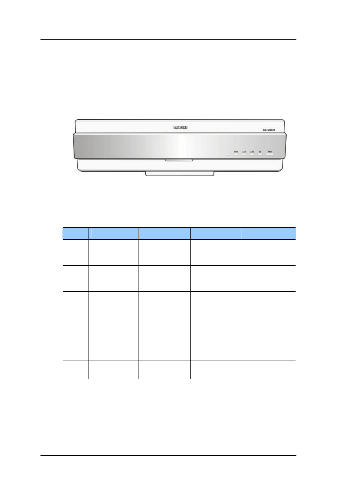
The front panel of SMT-R2000 is as shown in the figure below:
Figure 1.1 Front Panel of SMT-R2000
The following table describes each LED of the front panel:
Table 1.1 LEDs of SMT-R2000
LED Function Blue LED turns on Blue LED turns off Blue LED blinks
WAN WAN operation
status
LAN LAN operation
status
2.4 GHz 2.4 GHz operation
status
5 GHz 5 GHz operation
status
PWR Power supply
status
WAN is in normal
operation
LAN is in normal
operation
2.4 GHz Wireless
LAN is in operation
5 GHz Wireless
LAN is in operation
Power supply is
normal
WAN fails to
operate
LAN fails to operate Data is being
2.4 GHz Wireless
LAN fail to operate
5 GHz Wireless
LAN fail to operate
Power supply fails -
Data is being
transmitted/received
through WAN
transmitted/received
through LAN
Data is being
transmitted/received
through 2.4 GHz
Wireless LAN
Data is being
transmitted/received
through 5 GHz
Wireless LAN
1-2 © SAMSUNG Electronics Co., Ltd.
Page 13
SMT-R2000 Service Manual
1.2.2 Rear Panel of SMT-R2000
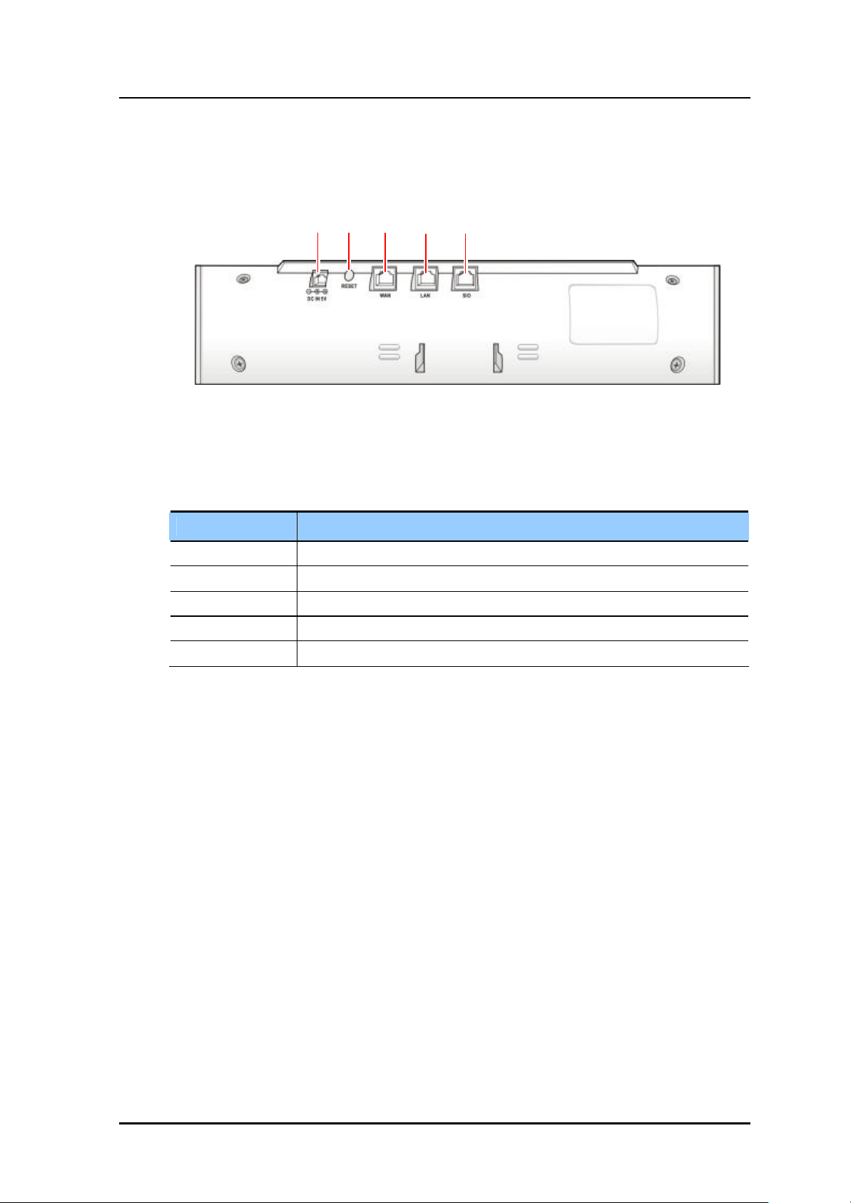
The rear panel of SMT-R2000 is as shown in the figure below:
LAN SIO DC5V RESET WAN
Figure 1.2 Rear Panel of SMT-R2000
The following table describes each port of the rear panel:
Table 1.2 Ports of SMT-R2000
Port Function
DC IN 5 V Port for connecting to local power supply adaptor(5 V, 2 A)
RESET External RESET input port of the system
WAN LAN port for connecting to WAN(RJ-45)
LAN LAN port for connecting to LAN(RJ-45)
SIO Used for connecting to PC to check the operational status of SMT -R2000
© SAMSUNG Electronics Co., Ltd. 1-3
Page 14
CHAPTER 1. Introduction of SMT-R2000
1.3 Hardware Specification
The SMT-R2000 hardware specification is as follows:
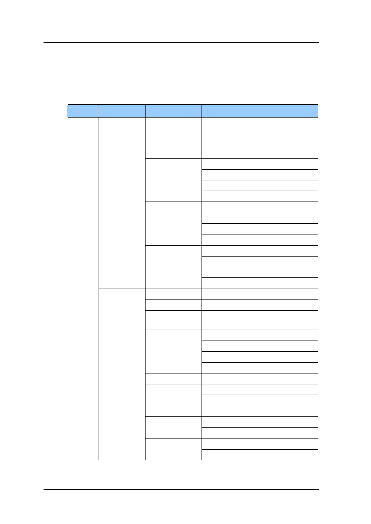
Table 1.3 SMT-R2000 Hardware Specification
Category Sub-Category
WLAN
IEEE 802.11a
Item Specification
Wireless Access CSMA/CA
Frequency 5.15~5.825 Ghz
Transmission
Method
Transmission
Output
Bandwidth 20 Mhz or less
Spectrum Mask
Adjacent Channel
Rejection
OFDM
14 dBm(25 mW) or more in 54 Mbps mode
15 dBm(30 mW) or more in 48 Mbps mode
16 dBm(50 mW) or more in 36 Mbps mode
17 dBm or more in other modes
-20 dBr or less at Fc+/- 11 Mhz
-28 dBr or less at Fc+/- 20 Mhz
-40 dBr or less at Fc+/- 30 Mhz
-65 dBm or less in 54 Mbps mode Receive Sensitivity
-82 dBm or less in 6 Mbps mode
-1 dB or more in 54 Mbps mode
16 dB or more in 6 Mbps mode
IEEE 802.11g
Wireless Access CSMA/CA
Frequency 2.4~2.4835 Ghz
Transmission
Method
Transmission
Output
Bandwidth 20 Mhz or less
Spectrum Mask
Adjacent Channel
Rejection
OFDM
14 dBm(25 mW) or more in 54 Mbps mode
15 dBm(30 mW) or more in 48 Mbps mode
16 dBm(50 mW) or more in 36 Mbps mode
17 dBm or more in other modes
-20 dBr or less at Fc+/- 11 Mhz
-28 dBr or less at Fc+/- 20 Mhz
-40 dBr or less at Fc+/- 30 Mhz
-65 dBm or less in 54 Mbps mode Receive Sensitivity
-82 dBm or less in 6 Mbps mode
-1 dB or more in 54 Mbps mode
16 dB or more in 6 Mbps mode
1-4 © SAMSUNG Electronics Co., Ltd.
Page 15
SMT-R2000 Service Manual
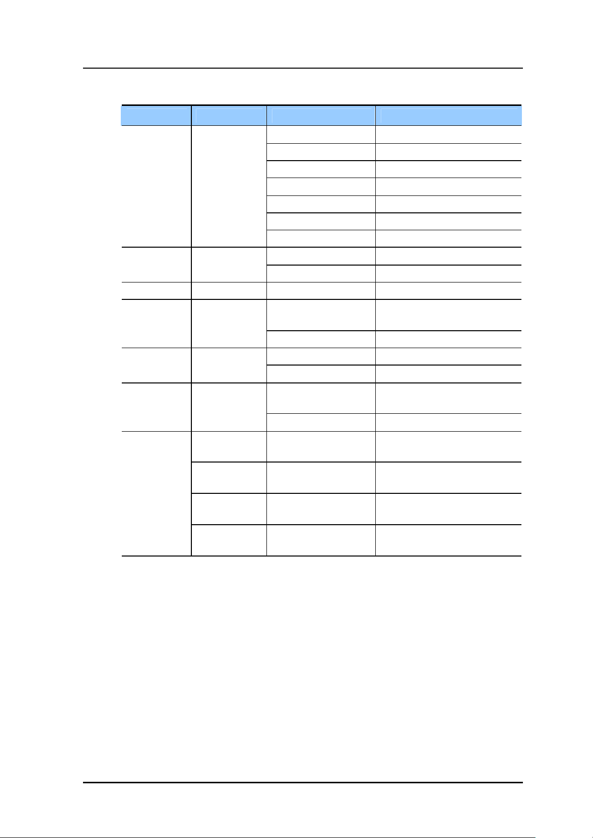
Table 1.3 SMT-R2000 Hardware Specification (Continued)
Category Sub-Category
WLAN IEEE 802.11b
ETHERNET - Link Speed Ethernet 10/100 base -T
Power Supply -
Wireless Access CSMA/CA
Frequency 2.4~2.4835 Ghz
Transmission Method DSSS
Transmission Method 17 dBm or more
Bandwidth 26 Mhz or less
Spectrum Mask Primary Sidelobe: -30 bBr or less
Receive Sensitivity -76 dBm or less(11 Mbps)
Built-in ANT 2 dBi Dipole ANT ANTENNA Diversity Support- default
Adaptor Input: 100~240 VAC, 50~60 Hz
POE Support- IEEE802.3af compliant
Dimension 115h x 60w x 35d(mm) Bottom Case Weight 148 g or less
Operational
Temperature
Item Specification
Output: 5 V, 2 A
0~45℃ Environment Temperature
Authentication
Storage Temperature -20~70℃
Korea Authentication for
specification
Europe Authentication for
specification
U.S.A. Authentication for
specification
Wi-Fi WLAN Compatibility test 802.11a/b/g Radio interoperability
MIC
CE
FCC
& WPA1.0
© SAMSUNG Electronics Co., Ltd. 1-5
Page 16
CHAPTER 1. Introduction of SMT-R2000
This page is intentionally left blank.
1-6 © SAMSUNG Electronics Co., Ltd.
Page 17
SMT-R2000 Service Manual
CHAPTER 2. Assembly and
Disassembly
This chapter describes how to disassemble and assemble SMT-R2000.
2.1 Configuration of SMT-2100C Main Board
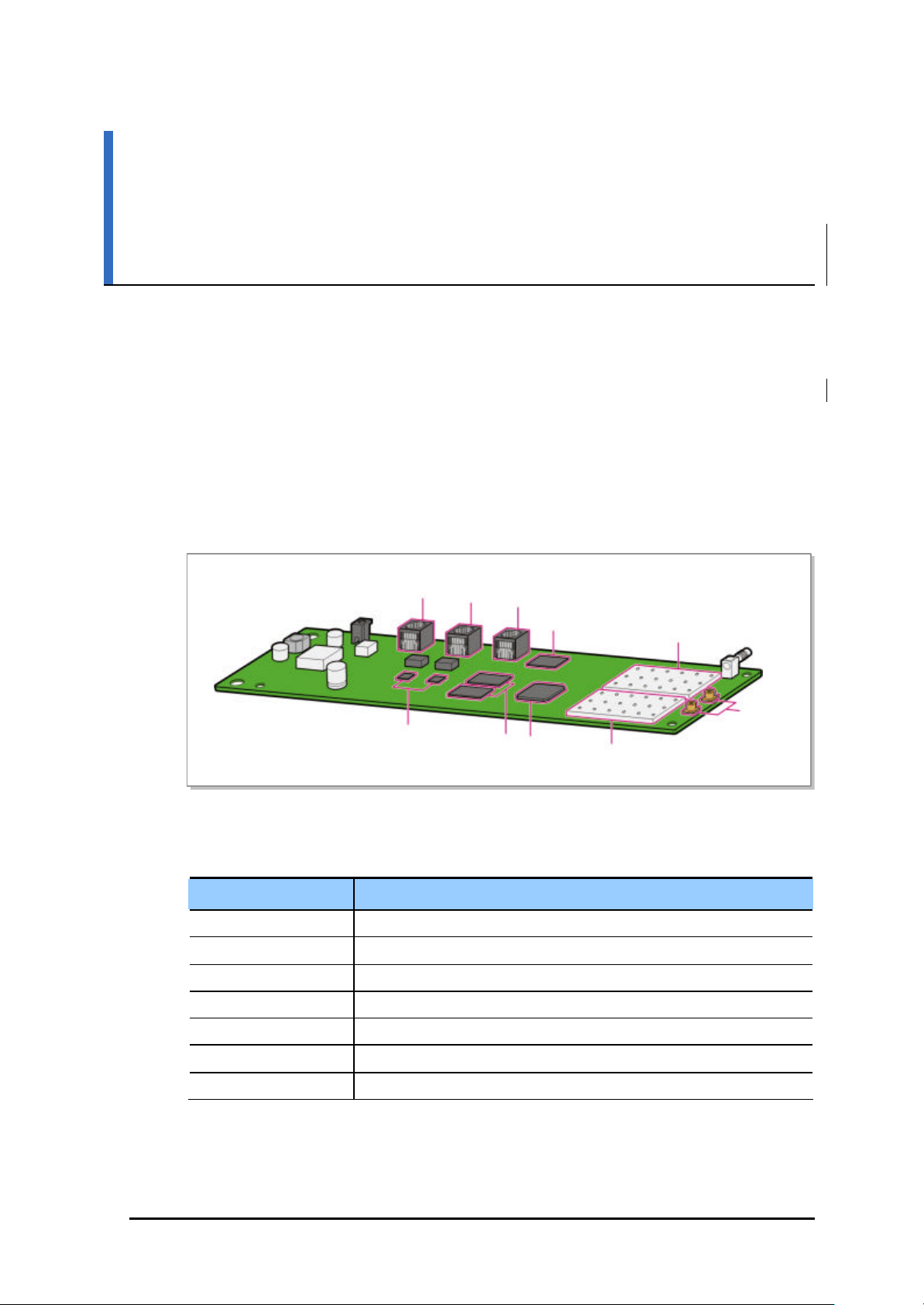
The configuration of the SMT-R2000 main board is as shown in the figure below:
WAN
Ethernet PHY
Figure 2.1 Configuration of SMT -R2000 Main Board
LAN
SDRAM
SIO
FLASH
CPU
RF Part(2.4 Ghz)
RF part(5 Ghz)
Table 2.1 Main Board Parts
Item Description
WAN/LAN/SIO Ports for connecting to WAN/LAN/SIO
FLASH BOOT/Application image storage memory
Ethernet PHY PHY CHIP for connecting to Ethernet 10/100 based
SDRAM Application-operation memory
CPU Main processor of SMT-R2000
Antenna
Connector
RF Part(2.4/5 GHz) RF part for supporting 802.11a/b/g
Antenna Connector Connector for connecting to built -in antenna
© SAMSUNG Electronics Co., Ltd. 2-1
Page 18
CHAPTER 12. Assembly and Disassembly
2.2 Disassembling
This section describes how to disassemble SMT-R2000.
The main body of SMT-R2000 is disassembled according to the following order:
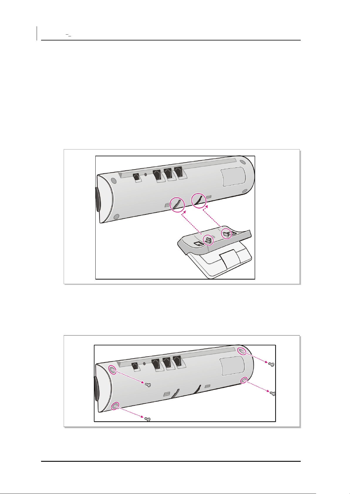
1) Separating the Stand from the Main Body
Separate the stand from the SMT-R2000 main body.
Push off the SMT-R2000 main body and the stand in opposite directions each other,
and then the stand is separated from the main body as shown in the figure below:
Figure 2.2 Separating the Stand
2) Separating the Case
Remove four screws from the bottom of the main body:
Figure 2.3 Removing Case Screws
2-2 © SAMSUNG Electronics Co., Ltd.
Page 19
SMT-R2000 Service Manual
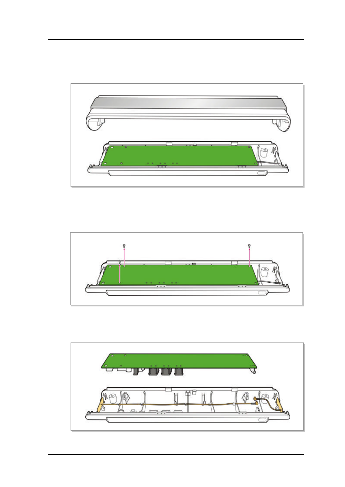
Hold on the ends of the case in the direction of the longer sides and pull out the case in
the opposite directions each other, to separate the case. The figure below shows an
example that the case is separated:
Figure 2.4 Separating the Case
3) Separating the Main Board and Bottom Case
Remove three screws fixing the main board and bottom case:
Figure 2.5 Removing Screws
Separate the antenna connector from the main board:
Figure 2.6 Separating the Main Board and Bottom Case
© SAMSUNG Electronics Co., Ltd. 2-3
Page 20
CHAPTER 12. Assembly and Disassembly
4) Separating the Shield Can
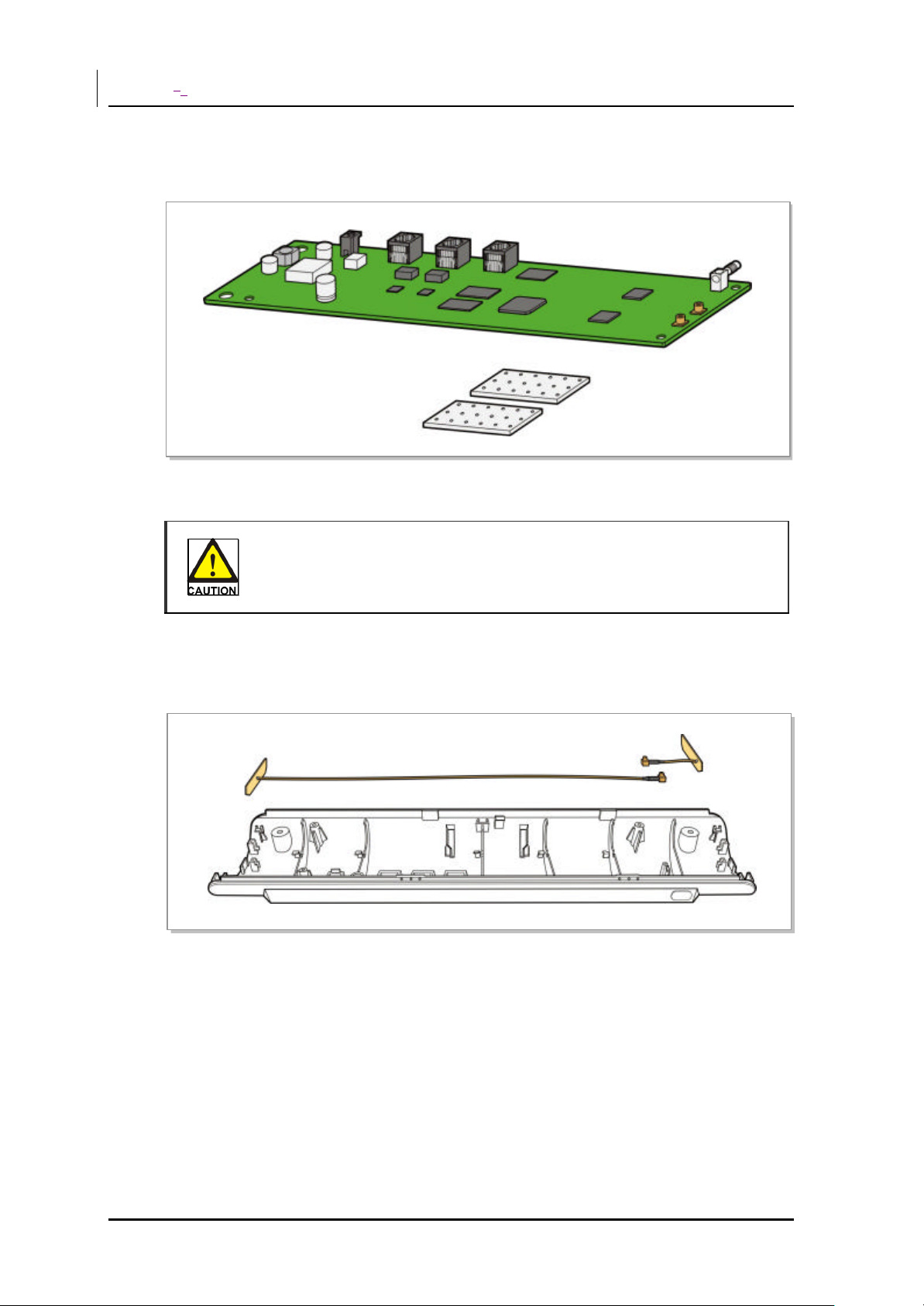
Separate the shield can covering the RF block:
Figure 2.7 Separating the Shield Can
Caution in Removing the Shield Can
Take care not to damage RF parts from heat when removing the shield can.
5) Separating the Antenna
Separate the antenna from the bottom case as shown in the figure below:
Figure 2.8 Separating the Antenna
2-4 © SAMSUNG Electronics Co., Ltd.
Page 21
SMT-R2000 Service Manual
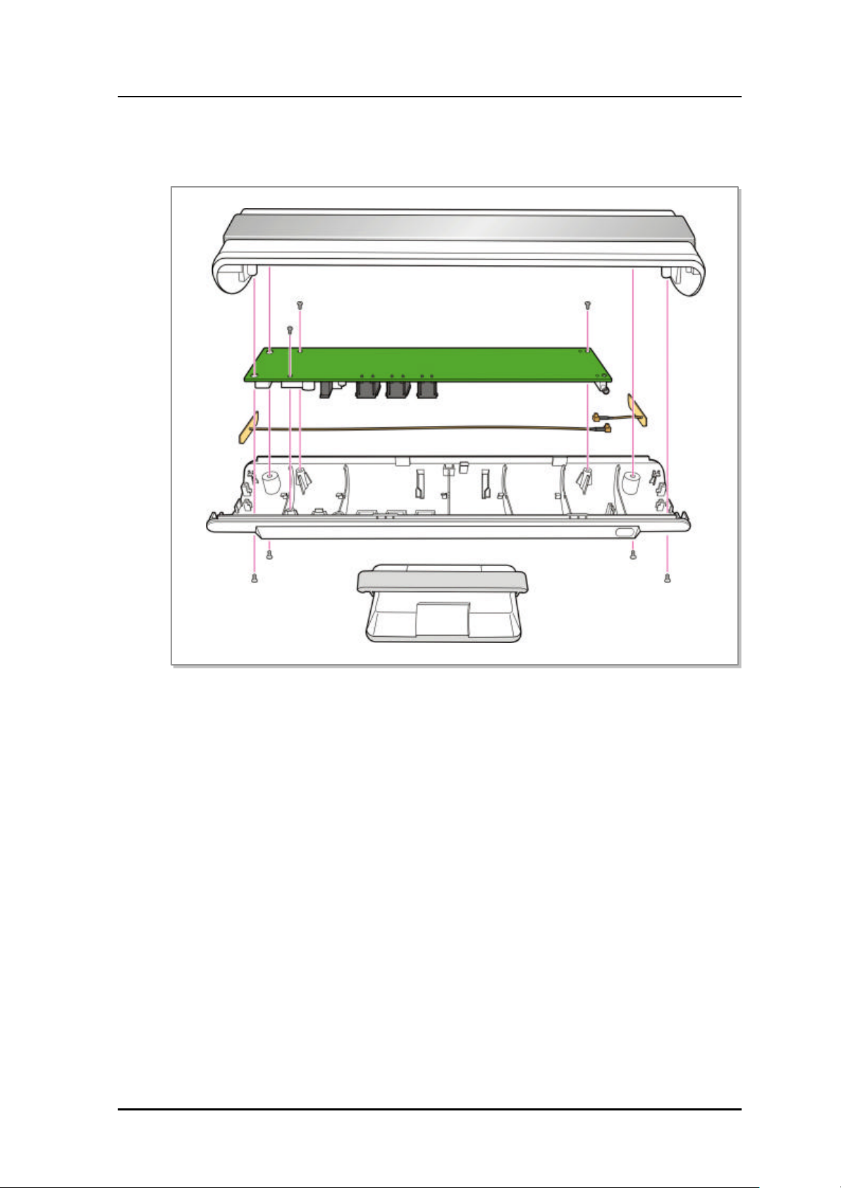
6) Completing the Disassembly
The figure below shows the status that the SMT-R2000 disassembly is completed:
2.3 Assembling
SMT -R2000 is assembled in the reverse order of ‘2.1 Disassembling’.
Figure 2.9 SMT-R2000 Disassembly Diagram
© SAMSUNG Electronics Co., Ltd. 2-5
Page 22
CHAPTER 12. Assembly and Disassembly
This page is intentionally left blank.
2-6 © SAMSUNG Electronics Co., Ltd.
Page 23

CHAPTER 3. Troubleshooting
This chapter describes the troubleshooting to the failures that can occur while using
SMT -R2000.
Page 24
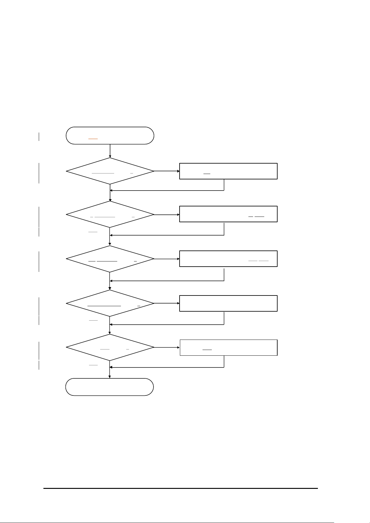
3.1 LED Failure
Failure Description
Nothing is displayed on LED even though SMT-R2000 has turned on.
Troubleshooting
LED has turned off
Is PWR LED normal?
Yes
Is 5 GHz LED normal?
Yes
Is 2.4 GHz LED normal?
Yes
Is WAN/LAN LED normal?
Yes
Is LED normal?
No
No
No
No
No
Refer to ‘3.2 Power Failure’.
Refer to ‘3.3 Wireless Failure -5 GHz’.
Refer to ‘3.4 Wireless Failure -2.4 GHz’.
Refer to ‘3.5 Network Connection Failure’.
Replace LED .
Yes
Termination
3-2 © SAMSUNG Electronics Co., Ltd.
Page 25
SMT-R2000 Service Manual
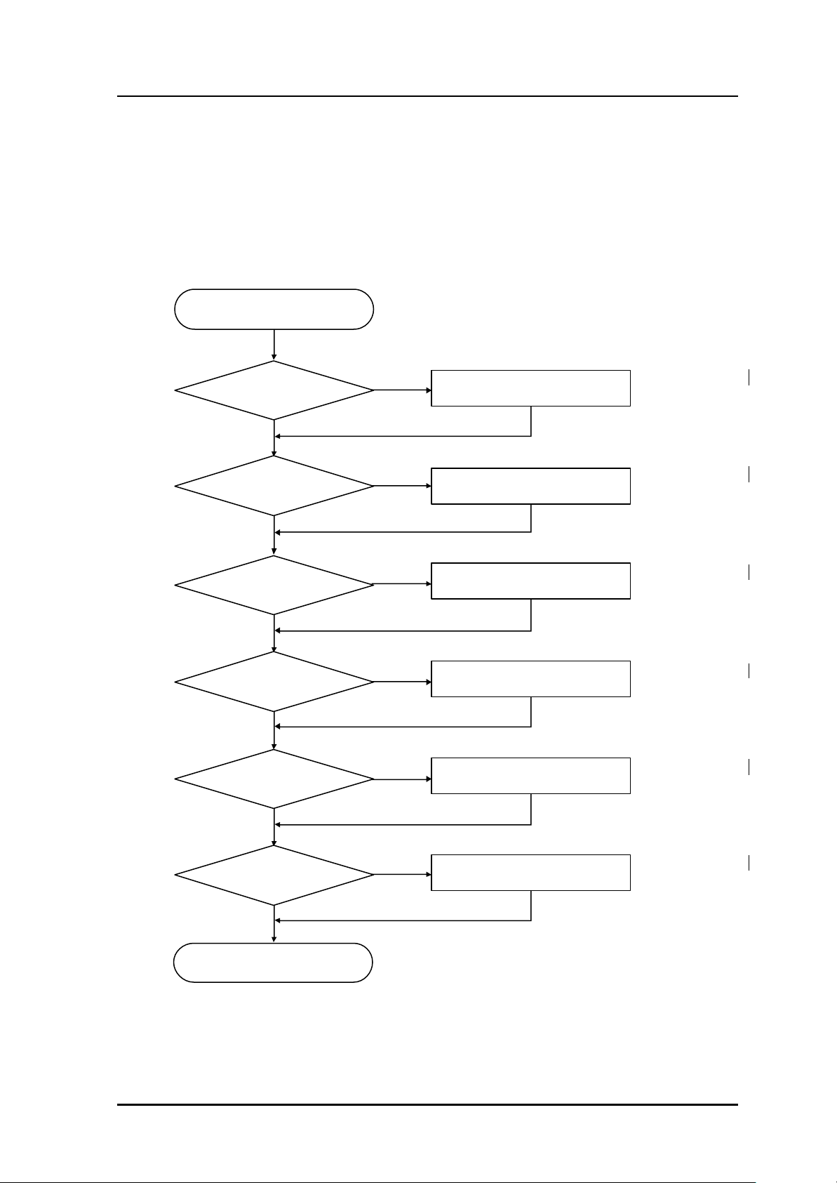
3.2 Power Failure
Failure Description
SMT -R2000’s body does not turn on because the power is not supplied to it.
Troubleshooting
SMT-R2000 does not turn on.
Is Power properly supplied?
Yes
Has Power Cable been
properly connected ?
Yes
Is Power Cable normal?
Yes
Is Power Jack normal?
Yes
Is Adapter normal?
No
No
No
No
No
Supply the Power.
Connect the Power Cable.
Replace the Power Cable.
Replace the Power Jack.
Replace the Adapter.
Yes
Is Regulator normal?
No
Yes
Termination
Check the soldering status of U32.
© SAMSUNG Electronics Co., Ltd. 3-3
Page 26
connector
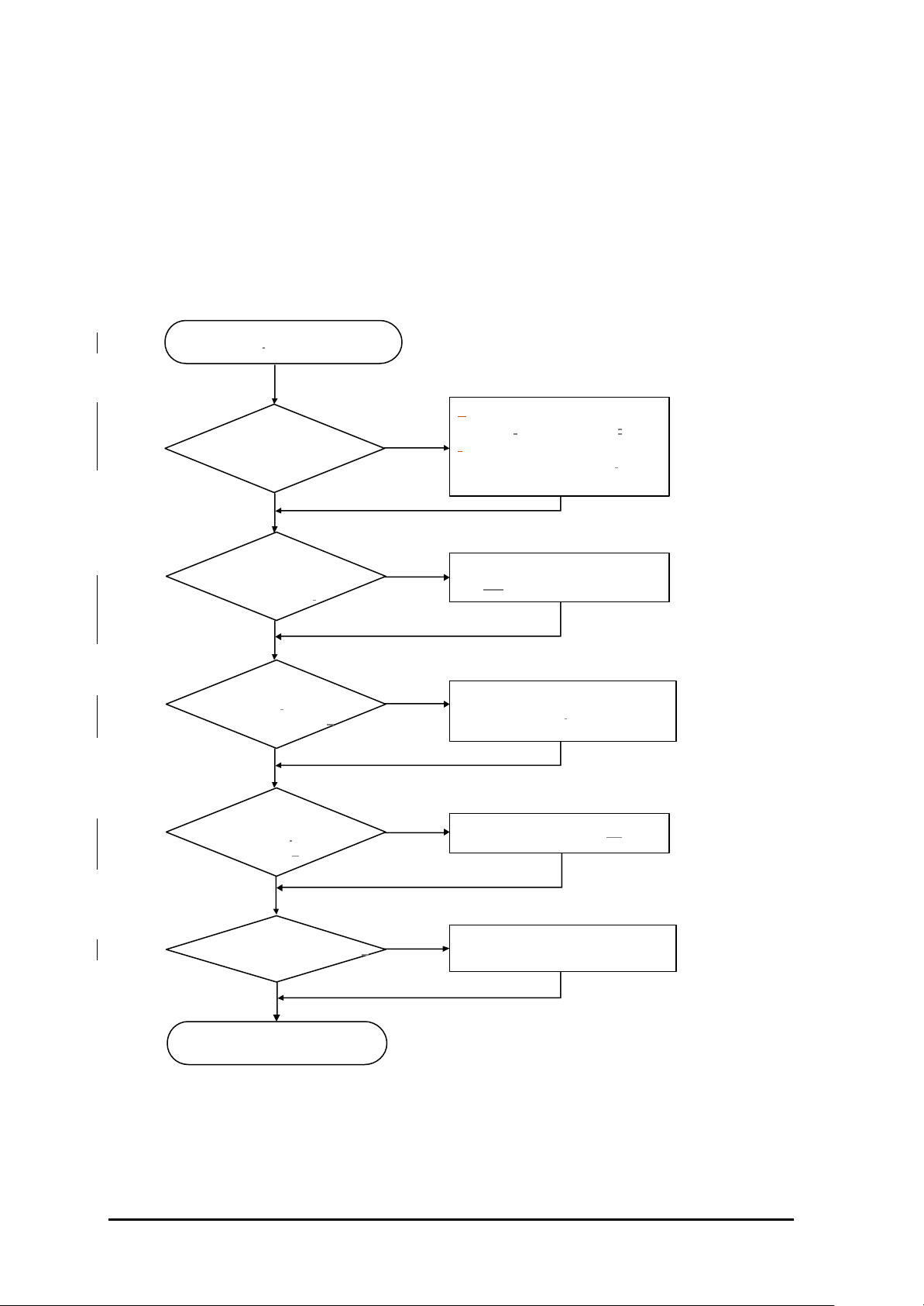
3.3 Wireless Failure -5 GHz
Failure Description
5 GHz(IEEE802.11a) Wireless LAN service cannot be used.
Troubleshooting
Wireless LAN cannot be connected.
- Make the distance between Wireless
Is the distance from
Wireless LAN to SMT-
R2000 short ?
Yes
No
LAN and SMT-R2000 short..
- Remove the foreign materials
between Wireless LAN and
SMT-R2000.
Can SMT-R2000 be
viewed through the scan
of Wireless LAN ?
Yes
Is the connector of
the built-in Antenna
properly connected?
Yes
Is the RF output of the
built -in Antenna
normal?
Yes
Is the reception signal normal?
No
No
No
No
Check the stuatus of the Wireless
LAN PC /Wireless LAN card.
Check the connection status of
the built-in Antenna connector.
Check the output status of U8.
Check the power/assembly satus.
Termination
3-4 © SAMSUNG Electronics Co., Ltd.
Page 27
SMT-R2000 Service Manual
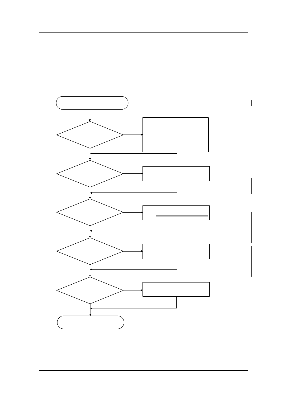
3.4 Wireless Failure -2.4 GHz
Failure Description
2.4 GHz(IEEE802.11b/g) Wireless LAN service cannot be used.
Troubleshooting
2.4 GHz Wireless LAN cannot be connected ..
- Make the distance between
Is the distance from
Wireless LAN PC to
SMT-R2000 short?
Yes
No
Wireless LAN PC and SMT-R2000
short.
- Remove the foreign materials
between Wireless LAN PC and
SMT-R2000.
Can SMT-R2000 be
viewed through the scan
of the Wireless LAN PC?
Yes
Is the connection of
the built-in Antenna’s
connector normal?
Yes
Is the RF output of the
built -inAntenna
connector (P2)
Yes
Is the reception signal
normal?
No
No
No
No
Check the status of the Wireless LAN
PC/Wireless LAN card.
Check the connection status of the
built-inSOC1(Mini PCI 珪??) ??
Check the output status of U6.
Check the Power/Assembly status of
Q3.
Termination
© SAMSUNG Electronics Co., Ltd. 3-5
Page 28
-
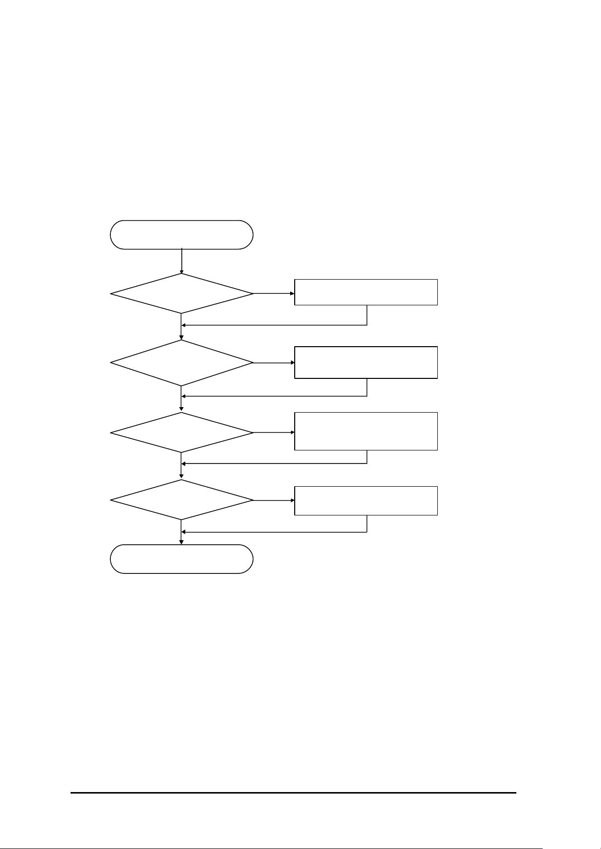
Replace Ethernet PHY.
3.5 Network Connection Failure
Failure Description
The access to Internet cannot be made bec ause the connection between SMT-R2000 and
Ethernet Network is not made.
Troubleshooting
The access to Internet cannot be made.
Is Ethernet normal? Check the Ethernet network status.
Yes
Has the modular jack
been properly connected?
Yes
Is Ethernet PHY normal?
Yes
Is T1, T5 normal?
Yes
Termination
No
No
No
No
Check the statuses of J2, J3connection
and the cable.
- Check the soldering status of U34,
U35.
- Check the soldering status of T1, T5.
- Replace T1, T5.
3-6 © SAMSUNG Electronics Co., Ltd.
 Loading...