

Graphic Symbol Explanation
The lightning flash with arrowhead symbol, within an
equilateral triangle, is intended to alert the user to the
presence of uninsulated “dangerous voltage” within the
product’s enclosure that may be of sufficient magnitude to constitute a risk of electric shock to persons.
The exclamation point within an equilateral triangle is intended to alert
the user to the presence of important operating and
maintenance (servicing) instructions in the literature
accompanying the appliance.
Warning-To Prevent Fire or Shock
Hazard,
Do Not Expose This Equipment To Rain or
Moisture.
IMPORTANT SAFEGUARDS
Caution
Power source is indicated on the rear of the set. It contains high-voltage parts. If you remove the cover, it may cause fire or electric shock.
Do not remove the cover by yourself. (Control switches are at the
front of the monitor.)
1. Read instructions: All the safety and operating instructions should be
read before the appliance is operated.
2. Retain instructions: The safety and operating instructions should be
retained for future reference.
3. Heed warnings: All warnings on the appliance and in the operating
instructions should be adhered to.
4. Follow instructions: All operating and use instructions should be followed.
5. Cleaning: Unplug this video product from the wall outlet before
cleaning. Do not use liquid cleaners or aerosolcleaners. Use a damp
cloth for cleaning.
Exception. A monitor that is meant for uninterrupted service and that
for some specific reason, such as the possibility of the loss of an
authorization code for a CATV converter, is not intended to be
unplugged by the user for cleaning or any other purpose, may exclude
the reference to unplugging the monitor in the cleaning description
otherwise required in Item 5.
6. Attachments: Do not use attachments not recommended by the video
product manufacturer as they may cause hazards.
7. Water and moisture: Do not use this video product near water - for
example, near a bath tub, wash bowl, kitchen sink, or laundry tub, in a
wet basement, or near a swimming pool, and the like.
8. Accessories: Do not place this monitor on an unstable cart, stand, tripod, bracket, or table. The monitor may fall, causing serious injury to
a child or adult, and serious damage to the appliance. Use only with a
cart, stand, tripod. bracket, or table recommended by Samsung, or
sold with the monitor. Any mounting of the monitor should follow
Samsung’s instructions, and should use a mounting accessory recommended by Samsung.
9. Ventilation: Slots and openings in the cabinet are provided for ventilation and to ensure reliable operation of the monitor and to protect it
from overheating, and these openings should never be blocked by
placing the monitor on a bed, sofa, rug, or other similar surface. This
monitor should never be placed near or over a radiator or heat register.
This monitor should not be placed in a built-in installation such as a
bookcase or rack unless proper ventilation is provided or Samsung’s
instructions have been adhered to.
10. Power Sources: This monitor should be operated only from the type
of power source indicated on the making label. If you are not sure of
the type of power supply to your installation site, consult your
Samsung dealer or local power company.
11. Grounding or Polarization: For monitors equipped with a 3-wire
grounding-type plug having a third(grounding) pin. This plug will
only fit into a grounding type power outlet. This is a safety feature. If
you are unable to insert the plug into the outlet, contact your electrician to replace your obsolete outlet. Do not defeat the safety purpose
of the grounding-type plug.
12. Power: Cord Protection-Power supply cords should be routed so that
they are not likely to be walked on or pinched by items placed upon
or against them, paying particular attention to cords at plugs, convenience receptacles, and the point where they exit from the monitor.
13. Lightning: For added protection for this monitor during a lightning
storm, or when it is left unattended and unused for long periods of
time, unplug it from the wall outlet and disconnect the cable system.
This will prevent damage to the monitor due to lightning and powerline surges.
14. Overloading: Do not overload wall outlets and extension cords as
this can result in a risk of fire of electric shock.
15. Object and liquid Entry: Never push objects of any kind into this
monitor through openings as they may touch dangerous voltage
points or short-out parts that could result in a fire or electric shock.
16. Servicing: Do not attempt to service this monitor yourself as open-
ing or removing cover may expose you to dangerous voltage or other
hazards. Refer all servicing to qualified service personnel.
17. Damage Requiring Service: Unplug this monitor from the wall out-
let and refer servicing to qualified service personnel under the following conditions.
a. When the power-supply cord or plug is damaged.
b. If liquid has been spilled, or objects have fallen into the monitor.
c. If the monitor has been exposed to rain or water.
d. If the monitor does not operate normally by following the operat-
ing instructions. Adjust only those controls that are covered by the
operating instructions as an improper adjustment of other controls
may result in damage and require extensive work by a qualified
technician to restore the monitor to its normal operation.
e. If the monitor has been dropped or the cabinet has been damaged.
f. When the monitor exhibits a distinct change in performance-this
indicates a need for service.
18. Replacement Parts: When replacement parts are required, be sure
the service technician has used replacement parts specified by
Samsung or have the same characteristics as the original parts.
Unauthorized substitutions may result in fire, electric shock or other
hazards.
19. Safety Check: Upon completion of any service or repairs to this
monitor, ask the service technician to preform safety checks to determine that the monitor is in proper operating condition.
Eng-2
CAUTION : TO REDUCE THE RISK OF ELECTRIC
SHOCK, DO NOT REMOVE COVER
(OR BACK). NO USER SERVICEABLE
PAR TS INSIDE. REFER SERVICING TO
QUALIFIED SERVICE PERSONNEL.
RISK OF ELECTRIC
SHOCK DO NOT OPEN
CAUTION

FCC & ICES Information
Warning
This equipment has been tested and found to comply the limits for a class
Adigital device, pursuant to part 15 of the FCC Rules and ICES-003 of
Industry Canada. These limits are designed to provide reasonable protection against harmful interference when the equipment is operated in a
commercial environment. This equipment generate, uses, and can radiate
radio frequency energy and, if not installed and used in accordance with
the instruction manual, may cause harmful interference to radio communications. Operation of this equipment in a residential area is likely to
cause harmful interference in which case the user will be required to correct the interference at his own expense.
User-Installer Caution
Your authority to operate this FCC verified equipment could be voided if
you make changes or modifications not expressly approved by the party
responsible for compliance to part 15 of the FCC Rules.
Information to user
Changes or modifications not expressly approved by the party responsible for compliance could void the user's authority to operate the equipment.
NOTE: This equipment has been tested and found to comply with the
limits for a Class A digital device, pursuant to Part 15 of the FCC Rules.
These limits are designed to provide reasonable protection against harmful interference when the equipment is operated in a commercial environment. This equipment generates, uses, and can radiate radio frequency
energy and, if not installed and used in accordance with the instruction
manual, may cause harmful interference to radio communications.
Operation of this equipment in a residential area is likely to cause harmful interference in which case the user will be required to correct the
interference at his own expense.
This device complies with Part 15 of the FCC Rules. Operation is subject
to the following two conditions: (1) this device may not cause harmful
interference, and (2) this device must accept any interference received,
including interference that may cause undesired operation.
Changes or modifications not expressly approved by the party responsible for compliance could void the user's authority to operate the equipment. If necessary, consult your dealer or an experienced radio/television
technician for additional suggestions. You may find the booklet called
How to Identify and Resolve Radio/TV Interference Problems helpful.
This booklet was prepared by the Federal Communications Commission.
It is available from the U.S. Government Printing Office,
Washington, DC 20402, Stock Number 004-000-00345-4.
The party responsible for product compliance:
SAMSUNG ELECTRONICS CO., LTD.
America QA Lab of Samsung
3351 Michelson Drive,
Suite #290, Irvine, CA92612 USA
IC Compliance Notice
This Class (A) digital apparatus meets all requirements of the Canadian
Interference-Causing Equipment Regulations.
Cet appareil numérique de la classe (A) respecte toutes les exigences du
Règlement sur le matériel brouilleur du Canada.
This Class A digital apparatus complies with Canadian ICES-003.
Cet appareil numéique de la classe A est conform à la norme NMB-003
du Canada.
Warning
This is a class A product. In a domestic environment this product may
cause radio interference in which case the user may be required to take
adequate measures.
Contents
IMPORTANT SAFEGUARDS ..................................................Eng-2
FCC &ICES Information ..........................................................Eng-3
Chapter 1: Overview ...................................................................Eng-4
Overview.................................................................................Eng-4
Functions and Features ...........................................................Eng-4
Names and Functions of Parts ................................................Eng-4
Chapter 2: Installation .................................................................Eng-6
Installation Environments.......................................................Eng-6
Unpacking...............................................................................Eng-6
CAMERA installation method................................................Eng-6
Chapter 3: Basic Connecting to External Devices.....................Eng-8
1. Connecting to Time Lapse VCR (or Normal VCR).........Eng-8
2. Connecting the Alarm Sensor............................................Eng-8
3. Connecting the Door Bell Box ..........................................Eng-8
4. Connecting the Ordinary monitor......................................Eng-9
Chapter 4: Basic Operation ........................................................Eng-9
1. Basic Operation .................................................................Eng-9
2. When you want to watch on LIVE/P.B./TRIPLEX
screen. ................................................................................Eng-9
3. When you want to watch in Full Screen Mode.................Eng-9
4. When you want to watch in Sequence Screen Mode........Eng-9
5. When you want to watch in FREEZE Screen Mode.........Eng-9
6. When you want to watch in FREEZE Screen Mode.........Eng-10
7. When you want to watch on PIP Screen Mode.................Eng-10
8. When you want to watch the VCR output.........................Eng-10
9. When you want to watch the Event Replay screen...........Eng-10
10. When you want to watch a Door Bell screen..................Eng-10
Chapter 5: Setup Menu Settings ................................................Eng-11
1. VIEW SETTING ...............................................................Eng-11
2. CLOCK/DISPLAY SET ....................................................Eng-11
3. CAMERA SETUP.............................................................Eng-12
4. SYSTEM SETTING..........................................................Eng-14
5. EVENT LIST.....................................................................Eng-16
6. DOOR BELL LIST............................................................Eng-16
Chapter 6: Recording ...................................................................Eng-16
1. Recording in Time Lapse (or Normal)Mode.....................Eng-16
2. Alarm/Motion Channel Intensive Recording.....................Eng-16
Chapter 7: Alarm,Motion,Loss and Door Bell...........................Eng-16
1. Alarm Occurrence..............................................................Eng-16
2. Motion Occurrence ...........................................................Eng-17
3. Loss Occurrence ................................................................Eng-17
4. Door Bell Occurrence........................................................Eng-18
Appendix........................................................................................Eng-18
Specifications..........................................................................Eng-18
Troubleshooting ......................................................................Eng-19
Eng-3
Chapter 1: Overview
Overview
The product is a triplex that enables you to record the signals
received from up to 8 cameras to a single VCR. You can record those
signals sequentially by frame or intermittently, and playback a specific channel selectively. You can use three monitor screen modes, LIVE
Mode, P.B. Mode, and LIVE + P.B. Mode, on a single monitor.
Functions and Features
• Set various functions using the Menu buttons.
• Connect up to 8 cameras for color or black-and-white pictures.
• Watch the input from up to 8 cameras on one screen in the various
split display modes.
• Watch the Live screen and the Playback screen simultaneously on
the same monitor.
• Enlarge a screen up to 2 Xs using the Zoom function.
• Utilize the Motion Detect function embedded in a camera.
• Monitor a specific screen within the main screen by using the Spot
Display function.
• Watch the Main screen simultaneously on an additional monitor
using the Slave Display function.
• Watch desired screens in still mode using the Freeze function.
• Switch and watch channels sequentially in Sequence mode.
• Hide the screens being displayed using the Hidden Camera function.
• The system has Date, Time and Alarm indicators that can be reset.
• When an Alarm occurs, the word "EVENT" is displayed on the
screen and a warning buzzer sounds. When this occurs, you can
press Enter and up to 16 frames before and after the generated
alarm will be replayed on the Event Replay window. Alarm histories are recorded in the EVENT LIST. The Alarm function is available only when the Alarm Box is connected.
• If the Channel Loss Detection function detects any channel loss,
the word "EVENT" is displayed on the screen and a warning
buzzer sounds. When this occurs, you can press ENTER and up to
16 frames before the detected chancel loss will be replayed on the
Event Replay window. Channel Loss histories are recorded in the
EVENT LIST.
• Due to the Door Bell Interlock Function, when the door bell is
pressed, the current picture switches to the doorbell area monitoring picture, in full screen mode, along with an alarming beep. At
this time, one Instant Picture is stored in the “DOOR BELL LIST”.
Up to 8 pictures can be stored in the “DOOR BELL LIST” You can
access any stored picture to be displayed on the screen. The Door
Bell Function is only available with a door bell connection.
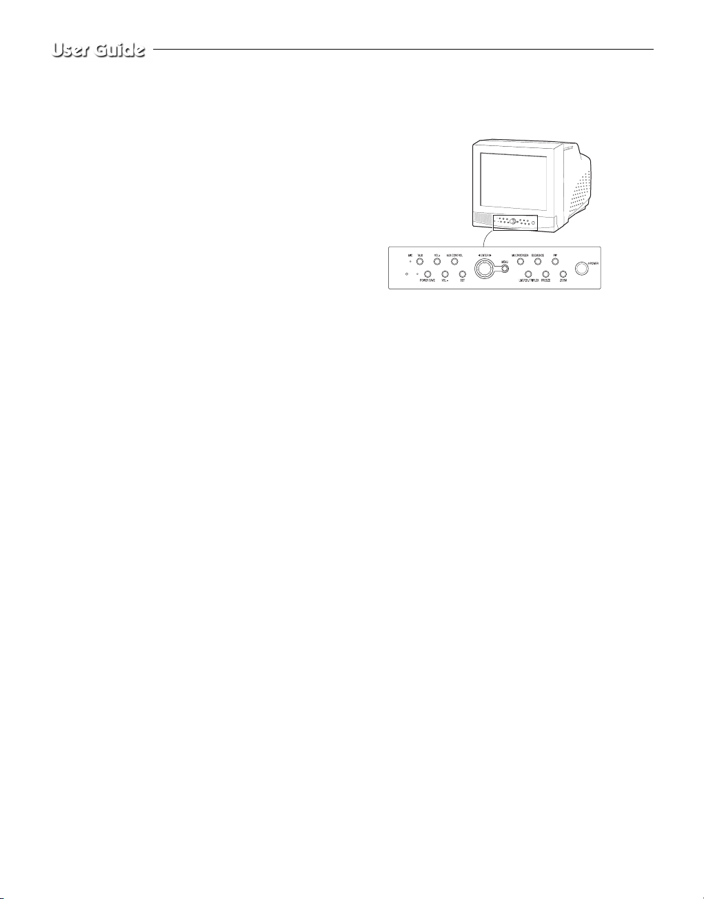
Names and Functions of Parts
Front Panel/Remote Control
A. Power Switch
Turns the power on/off.
B. POWER SAVE
Changes to Power Save mode.
C. VOLUME +/-
Controls the volume level.
D. TALK
Communicates with the doorbell in duplex mode.
E. AUX CONTROL
Outputs relay pulses to an external device for a specified time.
You can adjust this control according to your environment. (For example, when the doorbell rings, you can move to the corresponding camera and identify the visitor before opening the door using the AUX
CONTROL button.)
F. LIVE/P.B./TRIPLEX
Changes the Display mode. Each press of this button switches
between Live, P.B., and Triplex modes sequentially.
G. SET
Enters the selected Sub Menu from the Main Menu.
H. ROTARY WHEEL (LEFT, RIGHT, ENTER)
Press the LEFT button to direct the camera to the left; the RIGHT button, to the right. In the center is the ENTER button. Use this wheel to
move a Zoomed-in screen, or to scroll through Menu items or channels. Press ENTER to select an item, enter a sub menu, or replay the
events.
Eng-4
Eng-5
I. MENU
Display the Setup menu on the screen. Press it
again to exit the Setup menu.
J. MULTISCREEN
Switches to the split screen view. Each press
of this button changes to the 4, 8, and 9-split
screen sequentially. Only the 9 and 16 split
screens are available in the Triplex mode.
K. SEQUENCE
When pressed in the full screen mode, channels are switched automatically and sequentially within a specified time period.
L. FREEZE
Captures the selected screen as a still screen.
Refer to the section “When you want to
watch in FREEZE screen mode” on page
Eng-7.
M. PIP
Selects the Picture in Picture mode.
N. ZOOM
When pressed in full screen mode, the screen
is enlarged. Each press of this button enlarges
the screen two times sequentially and then
returns to the normal size. Use the Rotary
Wheel to move the Zoomed-in screen.
O. Number Key (0 ~ 9)
Press the number of the channel to watch it in full screen mode.
Or, press the SYSTEM ID button and then press the number of the
system you want to control with the remote control.
P. ZOOM (TELE/WIDE)
Only the remote control has this button. It is available only when a
camera (SOC-420(P), SOC-920(P) sold separately), is connected to
the system.
Q. FOCUS (FAR/NEAR)
Only the remote control has this button. It is used for camera Focus
control and available only when a camera (SOC-420(P), or SOC920(P), sold separately), is connected to the system.
R. IRIS (CLOSE/OPEN)
Only the remote control has this button. It is used for camera Iris control and available only when a camera (SOC-420(P), or SOC-920(P),
sold separately), is connected to the system.
S. ONEAF
Performs Auto Focus for the selected camera once in the present status. Only the remote control has this button. It is only available when
a camera (SOC-420(P), or SOC-920(P), sold separately), is connected
with the product.
T. SYSTEM ID
Selects the system to control with the remote. Only the remote control
has this button.
U. ID RESET
Located on the remote control, this button resets the selected System
ID to the default ID (1).
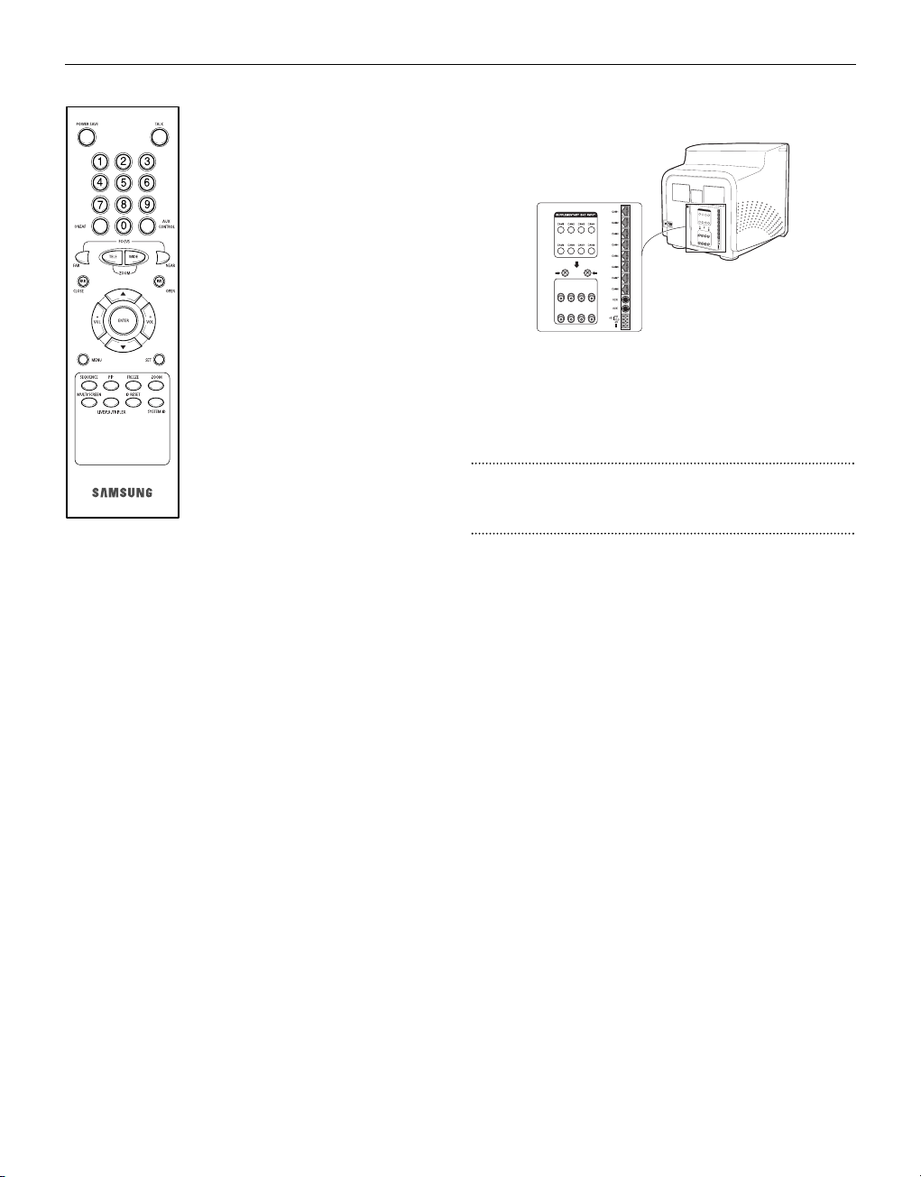
Rear Panel
A. CAMERA IN(RJ-45)
Video camera input terminals. You can connect up to 8 cameras
with RJ-45 connectors.
B. CAMERA IN (BNC)
Video camera input terminals. You can connect up to 8 cameras
with BNC connectors.
Caution
Either RJ-45 or BNC type cameras should be connected to the same
channel. Signal interference will occur if both types of camera are
connected to the same channel.
C. VCR
• Connects to the VCR using a 6-pin connector.
• TRIGGER: Trigger output terminal for the VCR
• VIDEO IN/OUT: Video input/output terminal for the VCR
• AUDIO IN/OUT: Audio input/output terminal for the VCR
D. AUX
• Connects to another device using the 4-pin connector.
• SPOT VIDEO OUT: The terminal that allows you to supervise the
specified channel within the Main screen on the additional connected
monitor.
• SPOT AUDIO OUT: The terminal that allows you listen to the sound
of the specified channel on the additional connected monitor.
• SLAVE VIDEO OUT: The terminal that allows you to view the Main
screen displayed at the present time on the additional connected
monitor.
E. ALARM
• A/O (HOT/COLD): When an alarm occurs, the Active Make signal
is output.
• A/R: Connects to the Alarm Reset terminal of VCR. When an alarm
is triggered, a pulse is output.
• G: Connects to the ground terminal of VCR.
F. ~AC IN
Connects the power cord.
Eng-6
Chapter 2: Installation
Installation Environments
This section describes the environmental requirements for safe installation and use.
Install the product on a flat table or in a rack. It should be used only
when level and should not be used when stood vertically or obliquely.
The location in which the main system is installed and the configuration
of the wiring room are very important for proper operation of the system.
When the products are installed too closely together or the location is
poorly ventilated, the system may not operate properly and maintenance
of the system may be difficult.
Sufficiently circulate the air within the system operating room and tightly
fasten the cover of the main system to prevent malfunction and reduce
system downs due to environmental causes.
There are high voltage parts inside. Do not arbitrarily open the cover.
Install the product in a place that meets the following environmental conditions. Be sure to maintain the system under the temperatures and
humidity conditions given below:
• Operating temperature : 0 °C ~ 40 °C
• Storage temperature : -20 °C ~ 60 °C
• Operating humidity : 20% ~ 85% RH
• Storage humidity : 20% ~ 95 RH
• Input voltage : AC 100 ~ 240V
• Frequency: 50/60 Hz
Caution
When operating the product, the fluctuation of input voltage must be
within 10% of the rated voltage and the external power outlet must be
grounded, otherwise, it may cause electric shock or malfunction of the
product. Do not connect heat-generating appliances such as a hair dryer,
iron or refrigerator to the same power outlet in which the product is
plugged, otherwise it may cause a fire or malfunction of the product. The
use of an Automatic Voltage Regulator (AVR) is highly recommended to
ensure that stable power is supplied.
Be sure to coil CORE-FERRITE on the connector to reduce elector-magnetic interference (EMI).
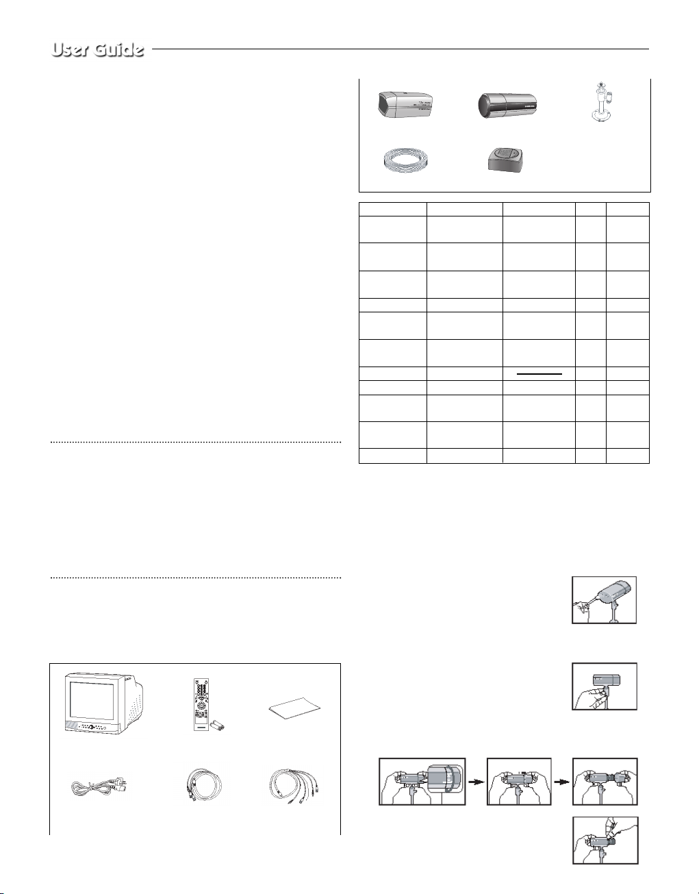
Unpacking
Remove the package cover and place the product on a flat and secure
surface or in the installation location. Check whether all the following
devices and accessories are included with the main system.
CAMERA installation method
1) Vari focal AI standard Camera (SOC-320P)
1. Find a suitable place for installing the camera. (Must be able to bear
five times the weight of the camera [approx. 1kg])
2. Install the Mounting Bracket provided at
the desired location, and assemble the camera
onto the bracket. Then connect the cable to the
RJ-45 connector.
3. Plug the other end of the cable that is connected to the camera into
the monitor.
4. Use the Handle on the Mounting Bracket when
adjusting the direction of view.
5. Adjusting Zoom and Focus.
5-1. Turn the lens part of the camera in the direction shown in the
picture and pull to separate the lens-hood.
5-2. Use the lens Zoom Lever to set the desired
zoom position.
6-Pin Accessory
(VCR)
Power Cord
4-Pin
Accessory(AUX)
Remote Control/
Batteries
Color Monitor
User’s Guide
Item
Monitor
Varifocal Camera
Zoom Camera
Door Bell
Camera Bracket
Camera Cable
Installation Manual
Power Cord
4-Pin
Accessory(AUX)
6-Pin
Accessory(VCR)
Remocon
Model
SMO-21MP/150MP
SOC-320P
SOC-420P
SDB-100
SBR-110
MCB-60
Description
21”/15” Flat CRT
Monitor
Normal Auto Iris
Va rifocal Camera
12X Zoom Lens
High Band Camera
Door Bell Box
Standard type
Bracket
8Pin Shield Cable
4-Pin AUX Cable
6-Pin VCR Cable
Q’ ty
1
1
1
1
2
3
1
1
1
1
Note
Screw2
Tapping
Screw6
60ft (1ft=
0.3048m)
Battery2
Cable
SDB-100
SOC-320P
SOC-420P
Camera Bracket
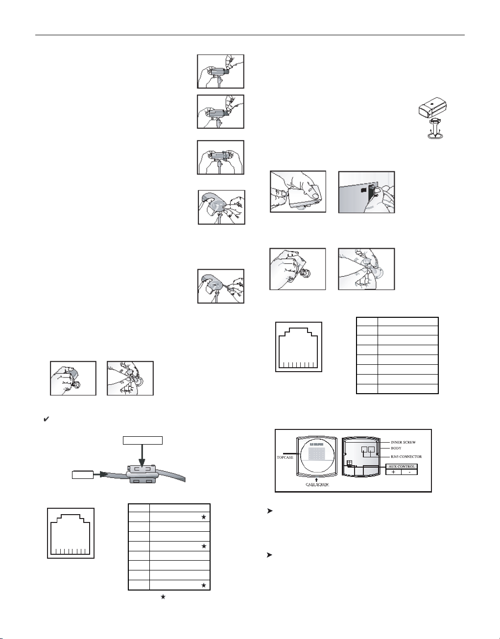
5-3. After setting this position, adjust the Focus
Lever to get the picture into focus.
5-4. When the zoom and focus settings are finished,
rotate the Zoom and Focus Levers to fix the ...
lens imposition.
5-5. After the adjustment, put the lens hood onto the
camera body and rotate it in the locking direction
to connect it.
6. Setting the brightness (lris setting)
The lris is adjusted in the factory prior to shipping:
however, users may need to adjust the opening
and/or closing of the lris according to the position
of installation, and ambient light conditions.
Use the Level VR located on the back of the camera
to optimize conditions.
7. Selecting FL-MODE Switch.
This function key is used to switch the anti-flicker
function ON/OFF.
Flicker effect occumence (due to power frequency
differences) may be eliminated by turning this key
‘ON’.
8. After the camera lens has been adjusted, use the camera mount
bracket to the direction you want to monitor and then fasten it tight.
Precautions
In case electroma gnelic waves affect SOC-320(P), please wind the core
ferrite at a proper point.
(The core ferrite is contained in SOC-320P only.)
Pin arrangement for the SOC-320P RJ-45 connector
2) 12X Zoom lens High Band standard Camera (SOC-420P)
1. Choose an installation site that can sufficiently support a minimum
of five times the net weight of the equipment to be installed
(approx. 800g).
2. Install the provided mounting bracket and then
connect one end of the cable to the rear of the
camera. When doing this, arrange the cable so
that it won’t get damaged or caught on anything.
3. Connect the other end of the cable to the monitor or other accessory
equipment.
4. Use the handle on the mounting bracket to direct the camera to the
area you want to monitor.
Pin arrangement for the SOC-420P RJ-45 connector
DOORBELL composition and installation method
AUX CONTROL
This output signal (DC17V, 300mA) that control external devices
when the AUX CONTROL key of the monitor or remote controller
is pressed.
CONNECTOR
One is for the camera-end of the cable, and the other is for the
monitor-end of the cable.
Eng-7
CORE-FERRITE
CABLE
8 ... 1
Pin No.
1
2
3
4
5
6
7
8
Pin Arrangement
DATA+
VIDEO_OUT
GND
DATA-
AUDIO_OUT
VDD
GND_V
CH_SEL
Pins indicated with ‘ ’ are not used.
8 ... 1
1
2
3
4
5
6
7
8
DATA+
VIDEO_OUT
GND
DATA-
AUDIO_OUT
VDD
GND_V
CH_SEL

Precautions for installation and use
Please check whether the installation site can sufficiently support the
weight of the SDB-100 before installation.
Make sure that the cable is not caught on anything or its insulation
sheath
is not removed.
(Neglecting to do to may cause fire or damage to the product.)
Prevent people from approaching the installation area, where object
might fall during installation. Move valuables to a safe location before
installation.
Install the SDB-100 in a cool location, away from direct sunlight. It is
recommended that SDB-100 is located in an area not subject to direct
sunlight during use or storage.
The SDB-100 must be used in an area where temperature and humidity
are kept within the limits specified below :
- Temperature : -10˚C ~ +50˚C (14˚F ~ 122˚F)
- Humidity : Below 90%
Installations
Choose an installation site that can sufficiently support a minimum of
five times the net weight of the equipment to be installed
(approzx. 500g).
1. Unscrew the CASE SCREW and then disassemble the TOPCASE.
2. Connect RJ45 CONNECTOR with the Camera, and connect the
other RJ45 CONNECTOR with the Monitor.
System connection is refer to system connection diagram.
3. If you want to use Aux Control. Connect the Aux Control +port
and -port with other device that use Aux Control output
(DC17V, 300mA).
4. After the cable connection is completed, you must arrange the
cables so that won’t get damaged.
5. Screw BODY of the SDB-100 and the satisfied place with the
INNER SCREW (2 point).
6. After, close the TOPCASE, screw TOPCASE and BODY with the
CASE SCREW.
System connection diagram
Chapter 3: Basic Connecting to
External Devices
The product can be connected to an external device such as a monitor,
VCR, Alarm Box, Door Bell Box, etc.
This chapter describes how to connect to external devices.
Caution
Make sure not to input more than 2V from the camera, video, or audio
source, otherwise, it may cause a malfunction of the product.
1. Connecting to Time Lapse VCR
(or Normal VCR)
1) Connect the 6-pin plug to the VCR terminal on the real panel.
2) Connect the VIDEO OUT plug to the VIDEO IN terminal of the
VCR.
3) Connect the VIDEO IN plug to the VIDEO OUT terminal of the
VCR.
4) Connect the AUDIO OUT plug to the AUDIO IN terminal of the
VCR.
5) Connect the AUDIO IN plug to the AUDIO OUT terminal of the
VCR.
6) Connect the TRIGGER plug to the REC TRIGGER OUT terminal
of the VCR.
7) Connect the A/O (HOT) terminal on the rear panel to the Alarm
IN terminal of the VCR.
8) Connect the A/O (COLD) terminal on the rear panel to the
Ground terminal of the VCR.
9) Connect the A/R terminal on the rear panel to the Alarm Reset
terminal of the VCR.
10) Connect the G (ground) terminal on the rear panel to the Ground
terminal of the VCR.
Caution
The name of the REC TRIGGER OUT or Alarm terminal may
change depending on the type of Time Lapse VCR.
Make sure to check the names of the terminals before connecting
them.
2. Connecting the Alarm Sensor
Connect the Alarm Box and Alarm Sensor in accordance with the
user manual of Alarm Box.
3. Connecting the Door Bell Box
Connect the cameras and Door Bell Box in accordance with the user
manual of Door Bell Box.
VIDEO IN
TIME LAPSE VCR
OR NORMAL VCR
VIDEO OUT
AUDIO IN
AUDIO OUT
VIDEO OUT
VIDEO IN
AUDIO OUT
AUDIO IN
TRIGGER OUT
TRIGGER
Eng-8

Eng-9
4. Connecting the Ordinary monitor
Connect the ordinary monitor to the Spot output terminal, which
allows you to supervise a specified channel within the Main screen.
Connect the Slave Monitor to the output terminal, which allows you
to simultaneously view the current situation.
Chapter 4: Basic Operation
1. Basic Operation
1) Turn the Power Switch On.
When turned on for the first time, the 9-split screens are displayed
on the monitor. At this time, the channels that have no input are
displayed with a blue screen and video loss occurs.(After completing the initial setup, the settings are memorized when the power is
turned off. Therefore, when you turn the power on again, the product will be operated with the previous settings.)
2) Select a Display Mode as follows.
• Full Screen Mode: When you are on a split screen, move to your
desired channel using the Rotary Wheel and press the ENTER
button located at its center. The selected channel will then be displayed in Full Screen Mode.
• Multi Screen Mode: Press the MULTISCREEN button to display
the split screens. You can select which channels will be displayed
on the split screen.
• Sequence Screen Mode: Press the SEQUENCE button. Channels
are automatically switched sequentially in full screen mode.
• Freeze Screen Mode: You can capture and view a still screen
using the FREEZE button and the Rotary Wheel.
• LIVE/P.B. Screen Mode: You can monitor the present camera
signals or playback the recorded screens using the
LIVE/P.B./TRIPLEX button.
• TRIPLEX Screen Mode: Watch the present camera signals and
recorded screens on the same monitor using the
LIVE/P.B./TRIPLEX button.
• PIP Screen Mode: You can watch Picture in Picture (PIP) screens
by using the PIP button.
• Zoom Screen Mode: You can enlarge a full screen two times
using the Zoom button and Rotary Wheel.
2. When you want to watch on
LIVE/P.B./TRIPLEX screen.
Select the LIVE, P.B., or TRIPLEX screen mode using the
LIVE/P.B./TRIPLEX button.
Each press of this button changes the screen mode to LIVE mode,
P.B. mode, and TRIPLEX mode sequentially.
The LIVE/P.B./TRIPLEX button will not operate in the following
cases:
• While using the SETUP Menu
• While displaying the Event List or the Door Bell List
• While replaying events
• While zooming-in the screen
• While setting a still screen on the multi screen mode
3. When you want to watch in Full Screen
Mode
If you are on a split screen, move to your desired channel using the
Rotary Wheel and press ENTER. The selected channel will be displayed in full screen mode. At this time, you can change the channel
using the Rotary Wheel.
In addition, you can change the channel by pressing number buttons
on your remote control.
4. When you want to watch in Sequence Screen
Mode
The Sequence screen is available only in full-screen LIVE mode.
Press the SEQUENCE button when the screen is in full-screen LIVE
mode to switch to the Sequence screen. You can set the switching
intervals by going to "SEQUENCE" under "4. SYSTEM SETTING"
on the SETUP MENU. The range of switching intervals is from one
to thirty seconds. Press the SEQUENCE button again to stop the
screen displayed at the present time.
The SEQUENCE button will not operate in the following cases:
• While operating in P.B. or TRIPLEX mode
• While using the SETUP Menu
• While displaying a split screen
• While displaying the Event List or Door Bell List
• While replaying events
• While zooming-in the screen
5. When you want to watch in FREEZE Screen
Mode
You can stop a full or split screen temporarily and view the still
screen in LIVE, P.B., TRIPLEX mode.
You can select and stop the channels you wish to stop in split screen
mode.
1) Full Screen Display
If the FREEZE button is pressed, the current display will freeze,
and the FREEZE icon will appear in the upper right corner of the
screen. Press the FREEZE button again to exit this mode.
2) Multi-Screen Display
! If the FREEZE button is pressed, the FREEZE icon will
appear in the upper right corner of the screen.
@ Move to the picture you would like to freeze by using Rotary
Wheel.
# By pressing the ENTER button in the middle of Rotary
Wheel, the picture from that channel will freeze, and the
character “F” will appear. Press the ENTER button again to
exit this mode.
VIDEO IN
AUDIO
IN
SPOT VIDEO OUT
SPOT AUDIO OUT
SLAVE VIDEO OUT
VIDEO IN

Eng-10
$ If you would like to see the frozen picture from another chan-
nel, move to the target channel, and press ENTER.
The new channel’s picture will be frozen, and the character
“F” will appear. Press the ENTER button again to exit this
mode.
% If the picture on any other channel remains frozen, repeat
item $)
^ Press the FREEZE button to exit entirely from FREEZE
mode.
The FREEZE button will not operate in the following cases:
• While using the SETUP Menu
• While displaying the Event List or Door Bell List
• While replaying events
6. When you want to watch on ZOOM Screen Mode
This mode is operated only while in LIVE/P.B. Mode Full Screen.
1) When the ZOOM button is pressed, a ZOOM AREAwill appear
in the center of the screen.
2) Move the ZOOM AREA to the target position by using the Rotary
Wheel and the ENTER button.
3) Press the ZOOM button again to increase picture to double its
original size.
4) Press it again to return to the original size.
ZOOM AREA and ZOOM Picture Movement
1) Press the ZOOM button and turn the Rotary Wheel to move the
ZOOM AREA up and down over the picture.
2) Press the ENTER button and turn the Rotary Wheel to move the
ZOOM AREA left and right over the picture.
3) Press the ENTER button again and turn the Rotary Wheel to
move the ZOOM AREA up and down over the picture.
The ZOOM button will not operate in the following case:
• While using the SETUP Menu
• While Displaying he EVENT List or Door Bell List
• While Replaying events
• While operating in Sequence Mode
7. When you want to watch on PIP Screen
Mode
You can watch a Picture in Picture screen in full-screen LIVE mode
using the PIP button.
When you press the PIP button for the first time, the sub screen on
the PIP screen is a sequence screen. After that, when you enter into
PIP mode again, the sub screen which is displayed in the same screen
mode as when you exited the PIP mode previously.
Using PIP Screen
1) Press the PIP button in full-screen LIVE mode.
2) When a fixed channel is displayed on the sub screen, each time
you press ENTER it switches between the Main screen and the
Sub screen.
3) Turn the Rotary Wheel to change the channel of the Main screen.
4) Press the SEQUENCE button to set the Sub screen as the
sequence screen. Press the button again to fix the channel.
5) You can change the position of the sub screen by going to “PIP
POSITION” under “2.CLOCK/DISPLAY SET” on the SETUP
menu.
The PIP button will not operate in the following cases:
• While operating in P.B. or TRIPLEX mode
• While displaying a split screen
• While using the SETUP Menu
• While displaying the Event List or Door Bell List
• While replaying events
• While zooming-in the screen
• While operating in Sequence mode
• In case of no Video input signal
• When the input signal channel is in the Full-screen mode at the
time of Single video input
8. When you want to watch the VCR output
Change to PB FULL Mode by pressing the Live/P.B./TRIPLEX
button. The “PB THROUGH” picture will appear if the ENTER
button is pressed while in this mode. Press the”ENTER” button
again to return to the previous PB picture.
Caution
This function is only available in PB FULL Display mode.
9. When you want to watch the Event Replay
screen
1) When an Alarm/Motion signal is input
You can use the alarm function only when an Alarm Box is connected. When an alarm/motion signal is input, the word "EVENT"
is displayed on the screen, and a warning buzzer sounds. When
this occurs, if you press ENTER, up to 16 frames before and after
the generated alarm/motion signal are replayed on the Event
Replay window.
Press ENTER again to stop the event replay.
If alarm/motion signals are input on more than one channel, press
ENTER to start the event replay for another channel when the
current event replay finishes. When an event replay for all the
channels on which an alarm/motion signal has occurred has finished, press ENTER to exit Event Replay mode.
Alarm/Motion histories are recorded in the EVENT LIST.
2) When Channel Loss is detected
If the channel loss detection function detects a channel loss, the
word "EVENT" is displayed on the screen and a warning buzzer
sounds. When this occurs, press ENTER and up to 16 frames
before the detected channel loss are replayed on the Event Replay
window.
Press ENTER again to stop the event replay. If channel loss is
detected on more than one channel, press ENTER to start event
replay for the next channel when the current event replay finishes.
When the event replay for all the channels on which channel loss has
been detected finishes, press ENTER to exit the Event Replay mode.
Channel loss histories are recorded in the EVENT LIST.
10. When you want to watch a Door Bell
screen
The Door Bell Function is only available with a door bell connection. When the door bell is pressed, the current picture switches to
the doorbell area monitoring picture, in full screen mode, along
with an alarming beep. At this time, one Instant Picture is stored in
the "DOOR BELL LIST". Up to 8 pictures can be stored in the
"DOOR BELL LIST".

You can access any stored picture from the list to be displayed on
the screen.
Move to your desired item by going to "5. DOOR BELL LIST" on
the SETUP menu and press ENTER to display it as a still screen.
Then, press ENTER again to return to the "DOOR BELL LIST"
screen.
Chapter 5: Setup Menu Settings
<SETUP MENU>
• Press the MENU button to display the Language Selection
screen.
• Select the desired language by using the Rotary Wheel and press
ENTER to display the SETUP MENU in the desired language.
• When you press the MENU button after completing the initial
language selection, the Language Select screen will not appear.
Instead the following SETUP MENU will appear on the monitor.
Press the button once again to return to the previous menu.
<SUB MENU >
• Select submenu 1 to 6 from the SETUP MENU using the Rotary
Wheel and press ENTER to go to the SUB MENU.
1. VIEW SETTING
You can change the contrast, brightness, color, sharpness and tint
of the Main screen on the monitor. Select “1. VIEW SETTING”
from the SETUP MENU using the Rotary Wheel and press
ENTER to display the following screen:
• Select an item using the Rotary Wheel and press ENTER to
change the preset value.
• Change the preset value (0 ~ 100) by using the Rotary Wheel
and press ENTER to save the setting.
• Select SAVE (save the changes), QUIT (exit the setting mode
without saving) or PRESET (reset all the settings to the factory
defaults) from the EXIT MENU and press ENTER to return to
the SETUP MENU.
Caution
The “TINT” item is only available in NTSC SYSTEM mode.
2. CLOCK/DISPLAY SET
You can change PIP position, display type, date type and time.
Select “2. CLOCK/DISPLAY SET” from the SETUP MENU using
the Rotary Wheel and press ENTER to display the following screen:
• Select an item using the Rotary Wheel and press ENTER to
change the preset value.
• Change the preset value using the Rotary Wheel and press ENTER
to save the setting.
• Press the MENU button to return to the SETUP MENU.
PIP POSITION: BOTTOM-RIGHT ↔ TOP-LEFT ↔ TOP-
RIGHT ↔ BOTTOM-LEFT.
• Select the PIP position among the four options listed above.
DISPLAY TYPE: ALL ↔ TITLE ↔ DATE/TIME ↔ NONE.
• ALL: All items will be displayed except the DATE/TIME and the
TITLE.
• TITLE: Only the CHANNEL TITLE will be displayed.
• DATE/TIME: Only the DATE/TIME will be displayed.
• NONE: Neither the DATE/TIME nor the TITLE will be displayed.
BORDER COLOR: GRAY ↔ BLACK
• GRAY : BORDER LINE COLOR is displayed in GRAY in
Multi Screen mode.
• BLACK : BORDER LINE COLOR is displayed in BLACK in
Multi Screen mode.
DATE TYPE: YY/MM/DD ↔ MM/DD/YY ↔ DD/MM/YY.
DATE [YY/MM/DD]
• Year(YY) : 00(2000) ~ 99(2099)
• Month(MM) : 01 ~ 12
• Day(DD) : 01 ~ 31
TIME [HH:MM:SS]
• Hour(HH) : 00 ~ 23
• Minute(MM) : 00 ~ 59
• Second(SS) : 00 ~ 59
[SETUP MENU]
1. VIEW SETTING
2. CLOCK/DISPLAY SET
3. CAMERA SETUP
4. SYSTEM SETTING
5. EVENT LIST
6. DOOR BELL LIST
[LANGUAGE]
ENGLISH
ESPAÑOL
FRANÇAIS
ITALIANO
DEUTSCH
NEDERLANDS
PORTUGUÊS
[VIEW SETTING]
CONTRAST 50
BRIGHT 50
COLOR 50
SHARPNESS 50
TINT 50
EXIT QUIT
[CLOCK/DISPLAY SET]
PIP POSITION BOTTOM RIGHT
DISPLAY TYPE ALL
BORDER COLOR GRAY
DATE TYPE YY/MM/DD
DATE[YY/MM/DD] 04/01/01
TIME [HH:MM:SS] 12:30:01
Eng-11

Eng-12
3. CAMERA SETUP
You can change the Camera ID, LOSS DETECT, MOTION
DETECT and Camera Preset values.
Select “3. CAMERA SETUP ”from the MAIN MENU using the
Rotary Wheel and press ENTER to display the following screen.
Select the desired channel using the Rotary Wheel and press ENTER
to go to the display of the selected channel. The following screen
will appear.
• All the items, except “CAMERA ID ”and “LOSS DETECT,” will
be available for setting only after the system is connected to a
camera (SOC-420(P) or SOC-920(P), sold separately).
• Select the desired item using the Rotary Wheel and press ENTER.
Then change the preset value using the Rotary Wheel and press
ENTER to complete the setting.
• Select SAVE (save the changes), QUIT (exit the setting mode
without saving) or PRESET (reset all the settings to the factory
defaults) from the EXIT menu and press ENTER to return to the
previous CAMERA SETUP menu.
You can’t return to the previous menu while in the setting mode.
You can only return to the previous menu by selecting EXIT.
• Change the preset values for the other channels repeating the same
steps.
• Press the MENU button after completing all the settings to return
to the SETUP MENU.
CAMERA ID:
---CH1----(“-” indicates blank.)
• Select “CAMERA ID” using the Rotary Wheel and press ENTER to
select the first “- .”
• Select the desired letter using the Rotary Wheel and press ENTER to
move on and select the next letter.
(Letter order: 0123456789ABCDEFGHIJKLMNOPQRSTUVWXYZ[
]~_ . / )
• Repeat the same to select all the desired letters. (You can choose up to
ten letters.)
LOSS DETECT:
Sets the Loss Detect On/Off. (ON ↔ OFF)
IRIS:
Controls the video output level through the Iris depending on the
level of light coming into the camera.
• Select “IRIS” using the Rotary Wheel and press ENTER to select
either “ALC...” or “MANUAL…”.
• ALC... : Auto Light Compensation
- Select “ALC...” using the Rotary Wheel and press the SET button to
display the following screen. Press the MENU button after completing the setting to return to the previous menu.
- Select AREA using the Rotary Wheel and press ENTER to select
either “PRESET...” or “USER…”.
- Select “PRESET...” using the Rotary Wheel and press the SET button to display the following screen. The back light compensation will
be applied to the area(s) with preset values.
Press the MENU button to return to the previous menu.
- Select “USER…” using Rotary Wheel and press the SET button to
display the following screen.
❙ Adjust the size up/downward using the Rotary Wheel and press
ENTER to select and move on to adjust the size on the left/right
side. Then “ ” will be displayed on the screen.
❙ Press ENTER after adjusting the size of the left/right side by using
the Rotary Wheel. Then you will be ready to adjust the position
up/downward and “ ” will be displayed on the screen.
❙ Press ENTER after adjusting the position using the Rotary Wheel.
Then you will be ready to adjust the position to the left/right side
and “ ” will be displayed on the screen.
❙ Press ENTER after adjusting the position using the Rotary Wheel.
Then you have completed the AREA setting. Press the MENU button to return to the previous menu.
- BLC (Back Light Compensation): When BLC is turned “ON,”BLC
function will be applied to all the areas set in AREA. When bright light
is in the background of an object, the object will appear dark on the
monitor due to the backlight. To address this problem, use the BLC
function so that you can get clear images.
- LEVEL: You may set the video output level from “-9” to “+9”.
Select “LEVEL [00]” using the Rotary Wheel and press ENTER to
change the setting. Press ENTER after changing the setting to save the
setting.
[SETUP CAMERA 1]
CAMERA ID ---CH1---LOSS DETECT ON
IRIS ALC...
SHUTTER OFF
WHITE BALANCE ATW
SPECIAL...
FOCUS ONEAF
MOTION DETECT...
EXIT SAVE
[ALC]
AREA PRESET...
BLC OFF
LEVEL[ 00 ] ----------+----------
[PRESET AREA]
[CAMERA SETUP]
SETUP CAMERA 1...
SETUP CAMERA 2...
SETUP CAMERA 3...
SETUP CAMERA 4...
SETUP CAMERA 5...
SETUP CAMERA 6...
SETUP CAMERA 7...
SETUP CAMERA 8...
[USER AREA]

• MANUAL...: Sets the manual opening/closing of the Iris.
- Select “MANUAL...” using the Rotary Wheel and press SET button to
display the following screen.
- Set the value using the Rotary Wheel.
- Press the MENU button to return to the previous menu.
SHUTTER
- You can set the high-speed electronic shutter speed, AUTO low-speed
shutter speed and FIX low-speed shutter speed.
- High-speed electronic shutter can be set to 7 shutter speeds ranging
from 1/120(1/100) sec to 1/10K sec. Auto low-speed shutter and FIX
low-speed shutter can both be set to 12 shutter speeds ranging from
X2 to X128.
- Low-speed slows down the speed of the shutter so that images taken
in dark light appear clearer on the screen. Select AUTO low-speed
shutter to detect the density of light and automatically slow down the
speed of the shutter depending on the density. Select FIX low-speed
shutter to set the speed of the shutter manually.
- The numbers following the AUTO and FIX items indicate the num-
ber of fields stored. The higher the number is, the lower the speed of
the shutter becomes. Images, therefore, appear most clear with still
pictures. With moving images, however, the object can appear
blurred.
- Setting the Value
From the SHUTTER Menu press ENTER to adjust the values. Select
the value using the Rotary Wheel and press ENTER to complete the
setting.
OFF ’ 1/120(1/100) ’1/250 ’ 1/500 ’ 1/1000 ’1/2000 ’ 1/4000 ’
1/10K ’ OFF ’AUTO X2 ’ AUTO X4 ’ AUTO X6 ’AUTO X8 ’
AUTO X12 ’AUTO X16 ’AUTO X24 ’AUTO X32 ’ AUTO X48 ’
AUTO X64 ’AUTO X96 ’AUTO X128 ’OFF ’ FIX X2 ’ FIX X4 ’
FIX X6 ’ FIX X8 ’FIX X12 ’ FIX X16 ’ FIX X24 ’FIX X32 ’ FIX
X48 ’ FIX X64 ’FIX X96 ’ FIX X128.
WHITE BALANCE:
AT W, AWC.., MANUAL...
• You can turn on the White Balance function that enables the color
white to appear normal regardless of the color temperature of light.
• ATW : Monitors the change in color temperature and adjusts the setting of the White Balance accordingly.
• AWC : Adjusts the setting of the White Balance to the color temperature only once and then maintains the setting. While in the AWC
screen, place a white paper in front of the camera and press the SET
button.
• MANUAL... : Select “MANUAL” using the Rotary Wheel and press
the SET button to display the following screen. Then you can choose
3200K, 5600K or USER Mode and set the White Balance manually
depending on the current lighting conditions.
- 3200K : Sets the color temperature at 3200° K.
- 5600K : Sets the color temperature at 5600° K.
- Set to “OFF[USER]” to display the following screen. Press ENTER
and then select the proper values of RED and BLUE to manually set
the color temperature.
Press the MENU button to return to the previous menu.
SPECIAL...
• Select “SPECIAL..” using the Rotary Wheel and press ENTER to display the following screen. Press the MENU button after completing the
setting to return to the previous menu.
• AGC : AGC(Auto Gain Control) function On/Off.
• MIRROR : Horizontally reverses the video output signals.
• D-ZOOM : Sets the magnifying rate of the Digital Zoom. This system offers up to 10X Zoom.
• POSI/NEGA : Sets the video output signals to either normal or
reverse output.
• ZOOM SPEED : Sets the moving speed of the Zoom.
- 1: Takes about 17 sec from x1 to x12 (the lowest speed)
- 2: Takes about 10 sec from x1 to x12 (low speed)
- 3: Takes about 6 sec from x1 to x12 (high speed)
- 4: Takes about 3 sec from x1 to x12 (the highest speed)
• DETAIL : Adjusts brightness vertically and horizontally.
FOCUS: Set the Focus to MF or ONEAF.
• MF: Manual Focus Mode allows the user to Focus.
• ONEAF: When the Zoom moves from the Wide to the Telephoto
direction, AF occurs only once after the Telephoto function is completed.
- ONEAF works like MF Mode when there are still images and
like AF Mode when the Zoom moves in the Telephoto direction.
MOTION DETECT...
• The Motion Detect feature is used to detect motion of an object. By
turning on the Motion Detect, you can detect the motion of an intruder
during non-peak hours.
• Select “MOTION DETECT” using the Rotary Wheel and press ENTER to
display the following screen. Press the MENU button after completing the
setting to return to the previous menu.
[MANUAL]
LEVEL[ 00 ] -------------+-------------
[MANUAL]
PRESET 3200K
[MANUAL]
PRESET OFF [USER]
RED [ 00 ] --------+-------BLUE[ 00 ] --------+--------
[SPECIAL]
AGC ON
MIRROR OFF
D-ZOOM OFF
POSI/NEGA +
ZOOM SPEED 3
DETAIL [ 0 ] -------+-------
Eng-13

Eng-14
• AREA SET : Sets the area of the screen to which the Motion Detector
is applied.
- PRESET...
❙ Select “PRESET” using the Rotary Wheel and press the SET but-
ton to display the following screen. The Motion Detect is applied
to the area(s) within the box.
Press the MENU button to return to the previous menu.
- USER...
❙ Select “USER... “ using the Rotary Wheel and press the SET but-
ton to display the following screen.
❙ Adjust the size up/downward using the Rotary Wheel and press
ENTER to select and move on to adjust the size of left/right side.
Then “ ” will appear on the screen.
❙ Adjust the size of the left/right side by using the Rotary Wheel and
press ENTER to select and move on to adjust the position
up/downward. “ ” will appear on the screen.
❙ Adjust the position up/downward using the Rotary Wheel and press
ENTER to select and move on to adjust the position of the
left/right side. “ ” will appear on the screen.
❙ Adjust the position of the left/right side using the Rotary Wheel
and press ENTER. Then you will have completed the AREA setting. Press the MENU button to return to the previous menu.
• SENSITIVITY: Sets the sensitivity of the Motion Detector to LOW,
MEDIUM or HIGH.
4. SYSTEM SETTING
You can change the ALARM, RECORD, HIDDEN CAMERA,
SEQUENCE, SYSTEM ID, PASSWORD, and LANGUAGE settings.
Select “4. SYSTEM SETTING” from the SETUP MENU using the
Rotary Wheel and press ENTER to display the following screen.
- Select an item using the Rotary Wheel and press ENTER to change
the setting.
- Change the setting using the Rotary Wheel and press ENTER to
save the setting.
- Press the MENU button after completing all the settings to return
to the SETUP MENU.
ALARM...
• Select “ALARM” using the Rotary Wheel and press ENTER to display
the following screen.
ALARM HOLD TIME
ALARM HOLD TIME is the time during which the Alarm continues.
You can set the duration at 5 sec, 15 sec, 30 sec, 1 min, 3 min, 5 min, 10
min, 20 min, 30 min or AUTO. When you select AUTO, the Alarm will
be on during the time the Alarm is signaling.
ALARM BUZZER
When the Alarm occurs, the Alarm Buzzer is set off. You can set the
duration at 5 sec, 15 sec, 30 sec, 1 min or OFF. When you select OFF,
the Alarm Buzzer will not sound.
• Select “ALARM PATTERN” using the Rotary Wheel and press
ENTER to display the following screen.
• You can select when to arm and disarm the alarm in two patterns.
When you select PATTERN A, The time in PATTERN B will be automatically modified.
• Select PATTERN A using the Rotary Wheel and press ENTER to display the following screen.
[MOTION DETECT]
AREA SET PRESET...
SENSITIVITY MEDIUM
[PRESET AREA]
[USER AREA]
[SYSTEM SETTING]
ALARM...
RECORD...
HIDDEN CAMERA...
SEQUENCE 02 [ SEC]
SYSTEM ID 1..
PASSWORD CHECK OFF
PASSWORD CHANGE..
LANGUAGE ENGLISH..
[ALARM]
ALARM HOLD TIME 01 [MIN]
ALARM BUZZER 05 [SEC]
ALARM PATTERN..
[ALARM]
ALARM HOLD TIME 01 [MIN]
ALARM BUZZER 05 [SEC]
ALARM PATTERN..
TIME 08:00 - 17:00 [PATTERN A]
17:00 - 08:00 [PATTERN B]
PATTERN A...
PATTERN B...

Eng-15
• Choose On/Off for the Motion, Alarm and Door-Bell features for all 8
cameras.
• Press the MENU button after completing the settings to return to the
ALARM Menu.
• Repeat the same for PATTERN B.
• The “--” will be displayed when it is not connected to the accessories.
RECORD...
• Select “RECORD…” using the Rotary Wheel and press ENTER to display the following screen.
REC TYPE
• NOR : Used for recording with a normal VCR. The picture is displayed according to the “REC OUT” set values (FIELD, FRAME).
• TLV: Used for recording through a time lapse VCR.
REC OUT
It is valid when the REC TYPE is “NOR”.
• FIELD : Records at 1/50 seconds (PAL), 1/60 seconds (NTSC).
• FRAME : Records at 1/25 seconds (PAL), 1/30 seconds (NTSC).
AUDIO RECORD
Sets the channel that sends Audio signals to the recoding output.
SPOT-OUTPUT
Sets the output channel for SPOT which will intensely monitor that
channel.
• Press the MENU button after completing the settings to return to the
SYSTEM SETTING Menu.
HIDDEN CAMERA
• Select “HIDDEN CAMERA…” using the Rotary Wheel and press
ENTER to display the following screen.
• Turn the Hidden Camera On/OFF of in LIVE Mode and P.B. MODE
for each channel.
• Press the MENU button after completing the settings to return to the
SYSTEM SETTING Menu.
SEQUENCE
• Set the Switching Interval for Sequence Mode. You can set the time
between 1 sec and 30 sec.
SYSTEM ID
• This function allows the user to control a single monitor using the
remote control when multiple (up to 10) monitors are linked together.
Only those monitors with IDs matching the Remote Control ID will be
controlled by the remote control.
• Setting: The default value of the monitor and the remote control is “1”.
The value of the Monitor ID can be set from 0 to 9 by accessing the
System ID Setup mode under the System Setting menu. Press the
System ID button on the remote control to display the Monitor ID and
the Remote Control ID as shown above. With system ID button
pressed, enter the desired number by pressing the corresponding button
(0 to 9) to set up the Remote Control ID. The OSD will disappear three
seconds after the last button is pressed.
PASSWORD CHECK
• Turns the Password Check On/OFF for entry into the SETUP MENU.
• When PASSWORD CHECK is “ON” for entry into the SETUP
MENU, the following screen will appear and the first space for a number will be selected.
• Select the first digit of the Password using the Rotary Wheel and press
ENTER to move to the next digit. Repeat this step to enter the six-digit
password and press ENTER to return to the SETUP MENU.
• If the Password is not correct, “ERROR TRYAGAIN” will appear at
the bottom of the screen. The message will disappear after the first
digit of the Password is entered. Repeat this step until you have entered
the six-digit password then press ENTER to move to the SETUP
MENU. If the number is entered incorrectly more than three times, the
display will return to the previous menu.
[PATTERN A]
CH MOTION ALARM DOOR-BELL
CH1 OFF -- OFF
CH2 OFF -- -CH3 -- OFF OFF
CH4 OFF OFF OFF
CH5 OFF OFF OFF
CH6 OFF OFF OFF
CH7 OFF OFF OFF
CH8 OFF OFF OFF
[RECORD]
REC TYPE NOR
REC OUT FRAME
AUDIO RECORD CH1
SPOT - OUTPUT CH1
[HIDDEN CAMERA]
CH LIVE P.B.
CH1 OFF OFF
CH2 OFF OFF
CH3 ON OFF
CH4 OFF OFF
CH5 OFF OFF
CH6 OFF OFF
CH7 OFF OFF
CH8 OFF OFF
CH1 CH2 CH3
CH4 CH5 CH6
CH7 CH8
MONITOR ID:1 REMOCON ID: 1
[PASSWORD CHECK]
++++++++++++++++++++++
+ - - - - - - +
++++++++++++++++++++++

Eng-16
PASSWORD CHANGE...
• Select “PASSWORD CHANGE...” using the Rotary Wheel and press
ENTER to display the current Password on the screen as shown
below. The first digit of the number will be selected. (Factory default is
123456.)
• Select the first digit of the Password using the Rotary Wheel and press
ENTER to select the second digit. Repeat the same until the six digits
of the Password have been entered. Press ENTER to complete the
change.
- You can use “0” to “9” for the Password.
LANGUAGE
• Select the desired language for the use in the Menu. ENGLISH,
ESPAÑOL, FRANÇAIS, ITALIANO, DEUTSCH, NEDERLANDS
and PORTUGUÊS are available.
5. EVENT LIST
You can check the ALARM/MOTION/LOSS EVENT LIST.
Select “5. EVENT LIST“ from the SETUP MENU using the Rotary
Wheel and press ENTER to display the following screen.
• The latest information on Alarms, Loss and Motion Detects will be
stored. This system stores up to 50 events (10 x 5 pages) staring
from the latest one. You can check the other pages of the List by
using the Rotary Wheel.
• Press the MENU button to return to the SETUP MENU.
6. DOOR BELL LIST
To check the EVENT LIST of the DOOR BELL(S).
Select “6. DOOR BELL LIST” from the SETUP MENU using the
Rotary Wheel and press ENTER to display the following screen.
• The latest information from the Door Bell detector will be stored.
This system stores up to 8 events starting from the latest one. Scroll
down the List using the Rotary Wheel and press ENTER to display
the still screen of the corresponding Door Bell. Press ENTER to
return to the DOOR BELL LIST.
• Press the MENU button to return to the SETUP MENU.
Chapter 6: Recording
1. Recording in Time Lapse (or Normal) Mode
• Image signals transmitted from up to 8 cameras play at 1/25 or 1/50
second intervals in PAL SYSTEM areas, and at 1/30 or 1/60 second
intervals in NTSC SYSTEM areas, and are recorded in the VCR.
• The TRIGGER OUT port of the VCR must be connected to the
TRIGGER (6PIN VCR Accessory) port of this system.
• When trigger signals from the VCR stop for more than 30 sec, the
Self Trigger mode is turned on to continue recording without the
trigger from the VCR.
2. Alarm/Motion Channel Intensive-Recording
• This system double-records channels in case of an Alarm/Motion.
• It records the Alarm/Motion channels in between recording the output channels.
• The “VIDEO LOSS” channel is also subject to the Alarm/Motion
Channel Double-Recording.
• Ex.) The ALARM is turned on at CH2.
Then MOTION occurs at CH5.
Chapter 7: Alarm, Motion, Loss
and Door Bell
1. Alarm Occurrence
The Alarm becomes available only when an Alarm Box is connected.
1) When an Alarm trigger is received, a warning buzzer sounds and
the screen is divided into 9 Live-Mode sub-screens. The word
“EVENT” appears on the screen and the Alarm occurrence information is displayed at the right bottom of the screen.
[SYSTEM SETTING]
ALARM...
RECORD...
HIDDEN CAMERA..
SEQUENCE 02 [SEC]
SYSTEM ID 1..
PASSWORD CHECK OFF
PASSWORD CHANGE.. 123456
LANGUAGE ENGLISH..
[ EVENT LIST] 1/5
YY/MM/DD HH:MM:SS CH
1 . 04/01/30 12:30:01 M 01
2 . 04/01/29 12:30:01 A 02
3 . 04/01/28 12:30:01 M 08
4 . 04/01/27 12:30:01 A 04
5 . 04/01/26 12:30:01 A 03
6 . 04/01/25 12:30:01 L 01
7 . 04/01/24 12:30:01 A 06
8 . 04/01/23 12:30:01 M 07
9 . 04/01/22 12:30:01 A 01
10. 04/01/21 12:30:01 A 01
[ DOOR BELL LIST]
YY/MM/DD HH:MM:SS CH
1 . 04/01/30 12:30:01 D 01
2 . 04/01/29 12:30:01 D 02
3 . 04/01/28 12:30:01 D 08
4 . 04/01/27 12:30:01 D 04
5 . 04/01/26 12:30:01 D 03
6 . 04/01/25 12:30:01 D 01
7 . 04/01/24 12:30:01 D 06
8 . 04/01/23 12:30:01 D 07
CH2: Alarm Occurs
CH5: Motion Occurs
CH2: Alarm Off
04/01/01 12:30:30
EVENT
CH1 CH2 CH3
CH4 CH5 CH6
CH7 CH8 A12345678

2) Press ENTER (in the middle of the Rotary Wheel) to replay the event
in Event Replay mode. Up to 16 screens can be replayed centering on
the time of the Alarm. The duration of Replay is displayed in a graph.
Turn the Rotary Wheel during the Replay to forward or reverse the
stored screens one by one.
Press ENTER to terminate the Event Replay. The Event Replay will
continue until ENTER has been pressed.
3) Alarm occurrence information is stored in the “EVENT LIST”.
4) Alarm Out (HOT, COLD) signals are active during the “ALARM
HOLD TIME. ”
• ALARM HOLD TIME : Time during which the Alarm function
is carried on after the Alarm is first detected. Alarm Hold Time
is reset automatically when Event Replay is turned on.
5) Recording output continues in Normal mode until the Alarm is
cleared. The recording frequency of the corresponding channel
increases.
6) Signals change as the Alarm occurs and later clears.
2. Motion Occurrence
The Motion option only becomes available when a camera with
Motion features is connected.
1) When a Motion trigger is received, a warning buzzer sounds and
the screen is divided into 9 Live-Mode sub-screens. The word
“EVENT ”appears on the screen and the Motion occurrence information is displayed at the bottom right of the screen.
2) Press ENTER (in the middle of the Rotary Wheel) to replay the event
in Event Replay mode. Up to 16 screens can be replayed centering on
the time of the Motion occurrence.
The duration of the replay is displayed in a graph.
Turn the Rotary Wheel during the Replay to forward or reverse the
stored screens one by one.
Press ENTER to terminate the Event Replay. The Event Replay will
continue until ENTER has been pressed.
3) Motion occurrence information is stored in the “EVENT LIST”.
4) Alarm Out (HOT, COLD) signals are active during “ALARM
HOLD TIME”.
5) Recording output continues in Normal mode until the Motion is
cleared. The recording frequency of the corresponding channel
increases.
6) Signal output continues as the Motion occurs and later clears.
3. Loss Occurrence
1) When the Loss occurs, a warning buzzer sounds and the screen is
divided into 9 Live-Mode sub-screens. The word “EVENT” and
Loss channel appears on the screen and the corresponding channel
appears Blue Black.
When more than one Loss occurs, that channel number display
switches to Blue-Black with a 1 second interval.
2) Press ENTER (in the middle of the Rotary Wheel) to replay the event
in the Event Replay mode. Up to 16 screens can be replayed centering
on the time before the Loss occurrence. The duration of the Replay is
displayed in a graph.
Turn the Rotary Wheel during the Replay to forward or reverse the
stored screens one by one.
Press ENTER to terminate the Event Replay. The Event Replay will
continue until ENTER has been pressed.
04/01/01 12:30:30
EVENT
CH2 CH3
CH4 CH5 CH6
CH7 CH8
1
ALARM
04/01/01
12:29:30
150ms or Above
VCR Trigger
Trigger ignored
Recording
Output
Time Lapse Mode
Normal Mode Time Lapse Mode
Alarm Output
Alarm Reset Output
Alarm/Motion Occurrence
Alarm Reset
04/01/01 12:30:30
EVENT
CH2 CH3
CH4 CH5 CH6
CH7 CH8
1
MOTION
04/01/01
12:29:30
04/01/01 12:30:30
EVENT
CH1 CH2 CH3
CH4 CH5 CH6
CH7 CH8 M12345678
04/01/01 12:30:30 L12345678
EVENT
CH1 CH2 CH3
CH4 CH5 CH6
CH7 CH8
04/01/01 12:30:30 L12345678
EVENT
CH2 CH3
CH4 CH5 CH6
CH7 CH8
1
LOSS
04/01/01
12:30:00
Eng-17

Eng-18
3) Loss occurrence information is stored in the ”EVENT LIST”.
4) When the corresponding camera is reconnected, the old settings
are canceled and the factory default settings are reinstated.
4. Door Bell Occurrence
The Door Bell option is only available when a Door Bell Box is connected.
1) When a door bell is pressed, the current picture switches to the
doorbell area monitoring picture, in full screen mode, along with
an alarming beep.
2) When the Door Bell is pressed, a still screen is stored in the
“DOOR BELL LIST”.
3) Up to 8 still images can be stored in the “DOOR BELL LIST” and
the selected List can be displayed on the screen.
4) Select the desired list from “6. DOOR BELL LIST ” in the
SETUP MENU and press ENTER in to replay the still screen of
the corresponding Door Bell.
Press ENTER again to return to the “DOOR BELL LIST”.
Appendix
Specifications
SDB-100
SOC-320P
SOC-420P
04/01/01 12:30:30
CH 1
NO.1 04/01/01
CH 5 12:30:30
Item
Product Type
Power Source Voltage
Power Consumption
Operating Humidity
Physical Size
Weight
Aux output
Microphone
Speaker
Description
Door Bell Box
DC 18V From Monitor
Approx. 1W
-10˚C ~ +50˚C
96mm(W) X 35mm(H) X 100mm(L)
Approx 100g
DC17V 300mA
-40dB
1W
Item
Product Type
Power Source Voltage
Power Consumption
Broadcast System
Image Device
Effective Pixel
Scanning Method
Line Frequency
Synchronization Method
Resolution
S/N Ratio
Minimum Sense Illumination
Color Temperature
Electronic Shutter
Signal Output
Lens
Operating Temperature
Operating Humidity
Physical Size
Weight
Description (SOC-320P)
Va rifocal DC Auto Iris Type Normal Camera
DC 12V ~ 18V From Monitor
Approx. 2W
PA L Standard Color camera
1/4 inch IT Super HAD CCD
500(H) X 582(V)
625 Line, 2:1 Interlace
Horizontal : 12.625Hz / Vertical : 50Hz
INT
330 TV Line
Over 48dB
2 Lux
AT W
ALC
Composite Video Out : 1.0Vp-p
75 Ohms / RJ45 Jack
3.4 ~ 9.0mm F1.6 Varifocal DC Auto Iris
-10˚C ~ +50˚C
~90%
62.5mm(W) X 51mm(H) X 119.5mm(L)
Approx 170g
Item
Product Type
Power Source Voltage
Power Consumption
Broadcast System
Image Device
Effective Pixel
Scanning Method
Line Frequency
Synchronization Method
Resolution
S/N Ratio
Minimum Sence Illumination
Color Temperature
Electronic Shutter
Black Light Compensation
Sense Up
Digital Zoom
Monitor Detection
Video Control
Signal Output
Lens
Operating Temperature
Operating Humidity
Physical Size
Weight
Description (SOC-420P)
12x Zoom lens Camera
DC 12V ~ 18V From Monitor
Approx. 6W
PA L Standard Color camera
1/4 inch IT Super HAD CCD
752(H) X 582(V)
625 Line, 2:1 Interlace
Horizontal : 15.625Hz / Vertical : 50Hz
INT
480TV Line
Over 48dB (AGC Off)
2 Lux (Sense Up Off)
0.02 Lux (Sense Up X128)
AT W/ AWC / Manual MODE
(3200˚K, 5600˚K, R/B Grin Control)
Off, 1/120, 1/250, 1/500, 1.1K, 1/2K. 1/4K, 1/10Ksec
Off / On (Area Setting)
Off / Auto x2 ~ x128/ Fix x2 ~ x128
Off, x2, x4, , x6, x8, x10
Off On (Area / Sensitivity, Detail Setting)
POSI/ NEGA/ MIRROR, Detail Setting
Composite Video Out : 1.0Vp-p
75 Ohms / RJ45 Jack
Focal length : 3.6 ~ 43.2mm
Aperture : F1.8 (Wide), F2.6 (Tele)
-10˚C ~ +50˚C
~90%
51.8mm(W) X 50.3mm(H) X 96.6mm(L)
Approx 160g

1. Model Name
- SMO-210MP
- SMO-150MP
2. Video Input
- CAMERA 8 Input : 1.0Vp-p, 75Ω (vertical),
RJ-45 Type, CVBS
- VCR 1 Input (to Video Out of VCR) : 1.0Vp-p, 75Ω (vertical),
S-Jack Type, CVBS
3. Video Output
- Monitor 2 Output
- SPOT : 1.0 Vp-p, 75Ω (vertical), S-Jack Type, CVBS
- SLAVE : 1.0 Vp-p, 75Ω (vertical), S-Jack Type, CVBS
- VCR 1 Output : 1.0 Vp-p, 75Ω (vertical), S-Jack Type, CVBS
4. Voice Input
- CAMERA 8 Input: RJ-45 Type
- VCR 1 Input (Audio Out-VCR) : S-Jack Type
5. Voice Output
- SPOT Audio
- VCR Audio
6. Alarm/Motion Function: Connected Alarm Box/Camera
- A/O (HOT, COLD): Relay Active
- A/R (Alarm Reset): Open Collector “L ” Level,
Pulse Width = 150ms or above
-Alarm Hold Time: Select 5sec, 15sec, 30sec, 1min, 3min, 5min,
10min, 20min, 30min, or AUTO.
- If AUTO is selected, the Alarm will be on during the time the Alarm
trigger is received.
7. Sequence
- Select between 01 sec to 30 sec.
8. Event Replay
- Alarm/Motion/Loss: Max. 16 Frames per Channel
- Door Bell: Max. 8 Frames
9. List
- Alarm/Loss/Motion: Saving Max. 50
- Door Bell: Max. 8
10. Multi Screen
- Full, 4, 8, 9, 16, Zoom, PIP
11. Horizontal Resolution
- 400 TV Lines or more (Live Mode Full Screen)
12. Memory Back Up
- 5 Years or more
13. Operation Temperature
- 0 °C ~ 40 °C
14. Built-in Clock
- ± 1 Minute/Month or less
15. CRT
- SMO-210MP : 21”FLAT CRT
- SMO-150MP : 15”FLAT CRT
16. Dimensions (W x H x D)
- SMO-210MP : 520 x 509 x 486
- SMO-150MP : 388 x 459 x 379
17. Weight
- SMO-210MP : 28kg (without packing)
32.5kg (with packing)
- SMO-150MP : 15.2kg (without packing)
18.5kg (with packing)
18. Power consumption
- Please see the regulatory label attached on the back of the monitor.
19. Video system
- SMO-210MP/150MP : ONLY PAL VIDEO SYSTEM
- SMO-210MP/150MP : ONLY NTSC VIDEO SYSTEM
Troubleshooting
You may encounter an unexpected problem while using this system that
makes it hard to use the system properly. In many cases, however, they are
minor problems rather than serious flaws in the system.
Refer to the following tips for some possible solutions.
If the problem persists, contact the local sales representative or service
center for support.
Note
If the problem is related to VCR recording or playback, check the VCR
as well.
Eng-19
When power will not come on
When the screen does not appear
When record is not working
When playback is not working
When the screen does not appear
in the Auto Sequence Switch
Mode
• Make sure that the cord is
properly plugged in.
• Check the power cable.
• Check the connections with
the camera, accessories and the
external monitor.
• Make sure the Video In port
of the VCR and the VCR
Accessory Video Out port of this
system are properly connected.
• Check if the tape inserted into
the VCR is able to record.
• Check that the REC Trigger Out
port of the Time Lapse VCR is
properly connected to the VCR
Accessory TRIGGER (6PIN
VCR ACCESSORY) port of this
system when you record in the
Time Lapse Mode.
• Make sure the Video Out port of
the VCR and the VCR Accessory
Video In port of this system are
properly connected.
• Check if the Display Mode of
this system is in P.B. Mode or
Triplex Mode.
• Check that the screen is in Live
Mode.
• Check that the time of
“SEQUENCE” under the SETUP
MENU is properly set.
 Loading...