

Samsung SMM-BMR004 User's Manual
EPB
ED.
Smart MBS
System De scr ipt ion /I nt roduc ti o n
Copyright
All text and images in this document are subject to the copyright of SAMSUNG Electronics Co., Ltd.
This document may not be reproduced, distributed, or modified without the written permission of SAMSUNG
Electronics Co., Ltd.
Trademark
The marks appearing on this document are trademarks of SAMSUNG Electronics Co., Ltd, its subsidiaries,
or affiliates.
This manual should be read and used as a guideline for properly installing and operating the product.
This manual may be changed for the system improvement, standardization and other technical reasons without prior
notice.
If you need updated manuals or have any questions co ncer ning the c onte nts o f the manu als , contact our Document
Center at the following address or Web site:
Address: Document Center 3rd Floor Jeong-bo-tong-sin-dong. Dong-Suwon P.O. Box 105, 416, Maetan-3dong
Homepage: http://www.samsungdocs.com
Yeongtong-gu, Suwon-si, Gyeonggi-do, Korea 442-600
©2011 SAMSUNG Electronics Co., Ltd. All rights r eserved.

INTRODUCTION
Smart MBS System Description
Purpose
Document Content and Organization
This document introduces charact eristics, features, and structure for Smart MBS Base Station of the
Samsung Multi-Modal System.
This document consists of 4 CHAPTERS, APPENDIX, and ACRONYMS.
Chapter 1. Samsung Multimodal System Abstract
Explains the following…
Smart MBS System Introduction
Samsung Multimodal System Network Configuration
Samsung Multimodal System Feature
Chapter 2. Smart MBS Abstract
Explains the following…
Smart MBS System’s Characteristics
Smart MBS ‘s Main Feature
Smart MBS ‘s Specification
Operation manual on Backhaul Interface
Chapter 3. HW Architecture of Smart MBS
Explains the following…
System Internal Structure
UADU (Universal Platform Digital Unit)
RRH (Remote Radio Head)
Thermal Radiation Structure
© SAMSUNG Electronics Co., Ltd.
I
INTRODUCTION
Chapter 4. SW Architecture of Smart MBS
Explains the following…
Smart MBS SW Structure
Loading Flow
ABBREVIATION
Provides definition for acronyms used in this document.
Conventions
Following symbols are used in this document. The information provided along with this symb ol should
be familiarized for safe operation/handling of the system.
Additional Reference
Provides reference in addition to the main contents.
Reference
Revision History
Rev. Date Note
1.0 2011.06 First Edition
II
© SAMSUNG Electronics Co., Ltd.

Smart MBS System Description
TABLE OF CONTENTS
INTRODUCTION I
Purpose ................................................................................................... I
Document Content and Organization
Conventions .................................................................................................. II
Revision History
Chapter 1. Samsung Multi-ModalSystem Abstract 1-1
1.1 Introduction to Smart MBS System ......................................................................... 1-1
Samsung Multi-Modal System N etwork A r chitecture ...................................................... 1-4
1.2
1.2.1 CDMA System Network Architecture ........................................................ 1-6
1.2.2
LTE System Network Structure ............................................................... 1-7
Samsung Multi-Modal Sy st em Featur e .................................................................... 1-10
1.3
1.3.1 CDMA System Feature ...................................................................... 1-10
1.3.2
LTE System Feature .......................................................................... 1-12
...................................................................... I
............................................................................................... II
Chapter 2. Smart MBS Abstract 2-1
2.1 Smart MBS System Description ............................................................................ 2-1
2.1.1 Smart MBS CDMA System Feature
2.1.3 Smart MBS LTE System Feature
2.2
Smart MBS Main Feat ure ................................................................................... 2-6
2.2.1 Physical layer Processing Feature
2.2.2 Call Processing Feature
2.2.3 IP Processing Feature ........................................................................... 2-10
2.2.4 Convenient Operation and Maintenance Feature
Smart MBS Specification .................................................................................. 2-14
2.3
2.4 Backhaul Interface Operation
Chapter 3. Smart MBS’s Hardware Structure 3-1
3.1 Internal System Architecture ..................................................................................... 3-4
3.1.1
CDMA Internal System Architecture ......................................................... 3-4
© SAMSUNG Electronics Co., Ltd.
............................................................. 2-3
................................................................ 2-3
.............................................................. 2-6
........................................................................... 2-9
........................................... 2-11
................................................................................. 2-19
III

TABLE OF CONTENTS
3.1.2 LTE Internal System Structure ............................................................... 3-6
3.2 UADU(Universal Platform Digital Unit) ........................................................................ 3-8
3.3 RRH (Remote Radio H ead )
3.4 Cooling Mechanism
3.4.1 Digital Unit (DU) ............................................................................... 3-17
3.4.2
RRH (Remote Radio Head) ................................................................. 3-17
3.5 Interface structure
Chapter 4. Smart MBS Software Architect ure 4-1
4.1 Smart MBS SW Architecture .................................................................................... 4-1
4.1.1 CDMA System Basic SW architecture
4.1.2 LTE System Basic SW Architecture
Loading Flow ................................................................................................ 4-7
4.2
ABBREVIATION I
.................................................................................... 3-14
............................................................................................ 3-17
.............................................................................................. 3-18
......................................................... 4-1
............................................................ 4-4
IV
© SAMSUNG Electronics Co., Ltd.

Smart MBS System Description
LIST OF FIGURES
Figure 1.1 Smart MBS System Schematic ................................................................... 1-2
Figure 1.2 Samsung Multi-modal Network Architecture .................................................... 1-4
Figure 1.3 CDMA Networ k A rchitecture of Samsung Multi-Modal System
Figure 1.4 Samsung Multi-Mode System’s L TE Network Architecture
Figure 1.5 CDMA System Functional Structure ........................................................... 1-10
Figure 1.6 Function of E-UTRAN and EPC
Figure 3.1 UADU Configuration - CDMA Single mode
Figure 3.2 UADU Configuration - LTE Single mode
Figure 3.3 UADU Configuration - CDMA + LTE dual mode
Figure 3.4 RRH-C2 (800MHz) .............................................................................. 3-3
Figure 3.5 RRH-P4(1.9GHz) ................................................................................ 3-3
Figure 3.6 Smart MBS CDMA Internal Block Diagram
Figure 3.7 Smart MBS LTE’ s I nternal Block Diag ram ...................................................... 3-6
Figure 3.8 UADU Configuration - CDMA Only
Figure 3.9 UADU Configuration - CDMA Only(Two UADU)
Figure 3.10 UADU Configuration - LTE Only ............................................................ 3-13
Figure 3.11 UADU Configuration - CDMA+LTE Dual Mode
Figure 3.12 UADU Configuration - CDMA+LTE Dual Mode(Two UADU)
Figure 3.13 UADU’s FAN Str ucture ....................................................................... 3-17
Figure 3.14 UADU’s Cooling Mechanism
Figure 3.15 HW Interface structure of UADU(CDMA)
Figure 3.16 HW Interface structure of UADU(L TE) ...................................................... 3-19
Figure 3.17 HW Interface structure of RRH-C2 ........................................................... 3-19
Figure 3.18 HW Interface structure of RRH-P4 ........................................................... 3-20
Figure 4.1 Smart MBS CDMA Software Architecture
Figure 4.2 CDMA Common Software Archit ecture
Figure 4.3 CDMA OAM Software Ar chitecture ............................................................. 4-3
Figure 4.4 CDMA Call Processing Software Structure
Figure 4.5 Smart MBS L TE Sof tw are Architecture
Figure 4.6 Smart MBS' Loading Signal Flow ............................................................... 4-8
................................ 1-6
..................................... 1-8
............................................................... 1-12
.................................................... 3-2
....................................................... 3-2
............................................... 3-2
.................................................... 3-4
.......................................................... 3-12
........................................... 3-13
............................................ 3-13
............................. 3-13
................................................................ 3-17
................................................... 3-18
...................................................... 4-1
......................................................... 4-2
...................................................... 4-3
.......................................................... 4-4
© SAMSUNG Electronics Co., Ltd.
V

TABLE OF CONTENTS
This page is intentionally left blank.
VI
© SAMSUNG Electronics Co., Ltd.

Smart MBS System Description
Chapter 1. Samsung Multi-Modal
System Abstract
1.1 Introduction to Sm art MB S System
As mobile telecommunication technology has experienced rapid growth from “Analog Mobile
Telecommunication(1
rd
2000(3
Generation)”, and into “WiMAX/LTE(4th Generati on)”, voice service is being expanded into
data service. Especially, “wire/wireless hybrid service”, “s martphone”, and “m obile terminal” increased
the demands for the high speed wireless technology. Along with the enhancement of various mobile
telecommunication networks, it is now becoming common for a single terminal to support different
mobile technologies.
“Smart MBS System” is multi-mode base station that will satisfy such needs of mobile
telecommunication market by integrating Voice(1X), Data(EVDO), WiMAX/
station equipment.
Smart MBS System mounts common DU(Digital Unit) Platform, and RRH (per each frequency
bandwidth) that operator can decide to configure it with either single or multiple mobile technology.
Smart MBS System provides CDMA(w/ FDD), LTE(w/FDD),
Smart MBS System supports the following telecommunication technologies.
CDMA2000 1X/1X Adv ance d
Having CDMA2000 1X as a ref erenc e, in tegr ate th e system (w/ EVRC-B, RLIC, QOF, New RC
algorithm) and the terminal(w/ ( e )QLIC, MRD, Ne w RC algorithm) to support 1X Advanced. As
a result, voice capacity enhancement will be provided.
CDMA2000 1xEV-DO Rev.A/Rev.B
Smart MBS supports CDMA2000 1xEV-DO Rev.A/Rev.B s ervice and data service of CDMA
network.
WiMAX IEEE 802.16e
WiMAX IEEE 802.16e System is a wireless network system that provides service based on IEEE
802.16 standard. IEEE 802.16 standard is basis of WiMAX, it contains IEEE Std 802.16-2004
which defines the fixed wireless interne t connection service, and P802.16-2004/Cor2/D3 which
defines the mobility algorithms such as handover and paging. WiMAX System uses
st
Generation)” to “Digita l Mobi le Telecommunication(2nd Generation)” to “ CD MA
LTE(4G) into a single base
WiMAX(w/TDD), and TD-LTE(w/TDD).
© SAMSUNG Electronics Co., Ltd.
1-1
Samsung Multi-ModalSystem Abstract
기존 기지국 시스템
OFDMA(Orthogonal Freque ncy Division Multiple Access) t ra nsmission algorithm with T DD(Time
Division Duplex) technology to provide a high speed data service, and larger coverage area when
compare d to e xis tin g wi re less LAN . Als o, h igh -end hardwar e is imp lement ed f or incr ease d s ystem
performance & capacity, and to provide various high speed data feature/service.
LTE (Long Term Evolution)
Samsung LTE System is a wireless network system that supports 3GPP LTE(Long Term
Evolution)(a.k. a. LTE). It improves the existing 3 GPP mobile telecom munication system(low
data throughput, but high in cost) to a next generation wireless network system which provides a
high speed data service with minimal cost. Samsung LTE System supports “Downlink
OFDMA”(Orthogonal Frequency Division Multiple Access) with either FDD(Frequency
Division Duplex)), “Uplink S C(Single Carrier) FDMA”, and “Scalable Bandwidth(for various
spectrum allocation)” to provide high speed data service. Also, high-end hardware is implemented
to improve system perform ance and capacity that various high speed data feature/servic e can be
provided.
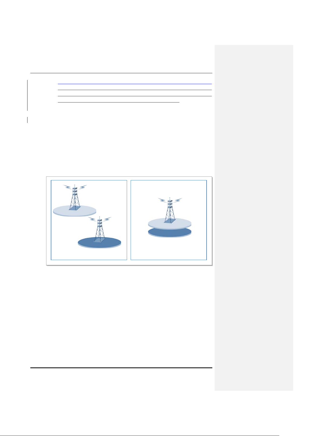
1.9 GHz(CDMA/LTE)
1.9 GHz(CDMA/LTE)
800 MHz(CDMA/LTE)
800 MHz(CDMA/LTE)
Samsung Smart MBS
Figure 1.1 Smart MBS System Schematic
Samsung Multimodal System consists of following major features.
Enhancement of CDMA Service Quality
In case “Smart MBS System” is operating CDMA, it provides “EVDO Rev.0/Rev.A and 1X
Advanced” in order to improve the low throughput and limited voice capacity. In addition, “2branch Rx
Diversity” and “4branch Rx diversit y” feature is provided that CDM A network coverage is enhanced for
versatile CDMA service.
Ease of Expanding 4G Ser vi c e
Legacy base stations c onsist of “3G CDMA 1X” for voice calls, “EVDO” for Data, “ Battery”, and
1-2
© SAMSUNG Electronics Co., Ltd.
Smart MBS System Description
“Rectifier”. If 4G service was to be supplied, additional 4G base station equipment had to be installed.
Nevertheless, “Smart MBS Base Station” on ly requires DU(Digita l Unit) cabinet and Battery cabinet to
provide existing service as well as 4G Service with minimal board replacements and software upgrades.
Therefore, Smart MBS Basesta tions u ti lizes the c ab les, rec tifie rs , and bat ter ies of the ex is ting b ases tati on
system. Its ease of 4G installation will bring about efficient network implementation in the future
commercial 4G service.
Green Solution
Smart MBS Basestation c ombines “3 G BS eq uipm ent” and th e “n ext gener ati on 4 G BS equ ip m ent” in t o
a single Base Station, and also c ontains the rectifier within the DU cabinet. Meanwhile, RRH(Remote
Radio Head) (TX/RX processing device) is separated apart from BS equipment for natural air cooling
that it can minimize footprint, power usage, and carbon dioxide emissions.
Provides Efficient Backhaul Operation
Smart MBS Basestation pro vid es fu ncti ona lit y that can operat e m u ltiple te lecomm unica tion technologies
into a single physical backhaul network for reducing backhaul expenses. In addition, it supports an
efficient backhaul operation b y providing a “per-technolog y” sectional net work operati on by logically
separating the backhaul, minimizing traffic interference between different technologies.
About Smart MBS
Smart MBS is basestation of Samsung Multi-Modal System that will provide BTS,
RAS, and eNB which will respecti ve ly serve the functionality of CDMA, and
WiMAX, and LTE. It is controlled by its respective upper NE (BSC for CDMA,
ACR for WiMAX, EPC for LTE) to handle CDMA/WiMAX/LTE calls. For
detailed description of function and structure of Smart MBS C DM A/ LTE, please
refer to Chapter 2,3,4 of this document. For the functio n a nd structure of Smart
MBS WiMAX, please refer to the additional document.
© SAMSUNG Electronics Co., Ltd.
1-3
Samsung Multi-ModalSystem Abstract
SMS
VMS
SCP
STP
DPI
HA
Packet Data
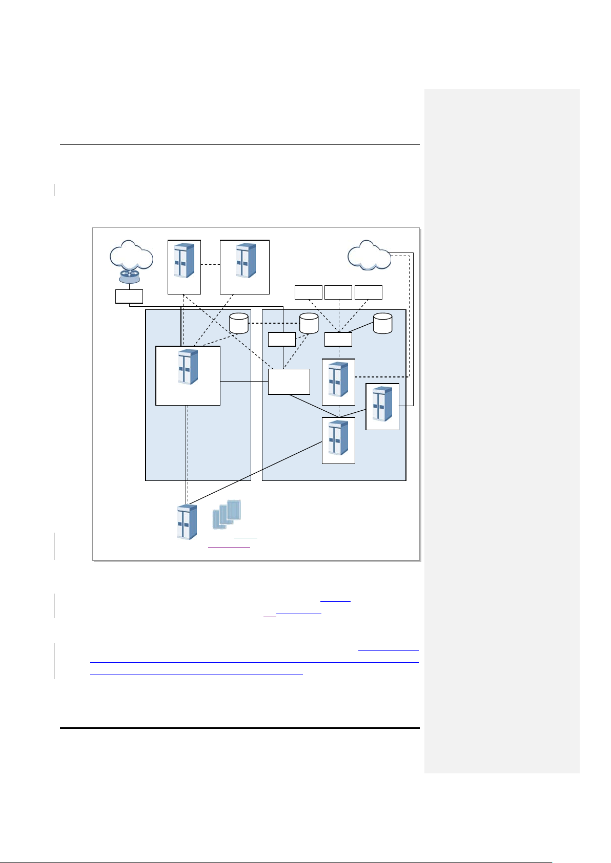
1.2 Samsung Multi-Modal System Network Archit ect u re
Samsung Multi-Modal System is configured as shown in following Figure 1.2.
A1p
PSTN
MAP
A2p
Network
Sp
PCRF
Gx
EPC
(MME/S-GW/P-GW)
S1
IMS-HSS
LTE-HSS/SPR
S6a
AAA
PMIP
Radius
HSGW/
PDSN
MAP MAP WIN
AAA
Radius
A10/A11
MSCe
BSC/RNC
CDMA LTE
HLR
MGW
RRU
CDMA/LTE/WiMAX
(800 M, 1.9 G)
Figure 1.2 Samsung Multi-modal Network Architecture
As shown in Figure 1.2, Smart MBS system plays a role as CDMA/WiMAX/LTE basestation in a
Samsung Multi-Modal System network where CDMA, and WiMAX, and LTE systems co-exist.
When operating as CDMA, Smart MBS commu nicates with BS C(CDMA controller), and operator m ay
use BSM(EMS of CDMA) to c ontrol and manage CDMA portion of Smart MBS. When operating as
WiMAX, it communicates with ACR(WiMAX controller), and operator may use WSM(EMS of
WiMAX) to contr ol and mana ge WiMAX por tion of Sma rt MBS. Likewise, when operating as LTE, it
communicates with EPC, and operator may use LSM-R(EMS or LTE) to control and manage LTE
portion of Smart MBS.
1-4
© SAMSUNG Electronics Co., Ltd.

Smart MBS System Description
Following network structure describes the type of each technology supported by Smart MBS.
© SAMSUNG Electronics Co., Ltd.
1-5
Samsung Multi-ModalSystem Abstract
Proprietary
Proprietary
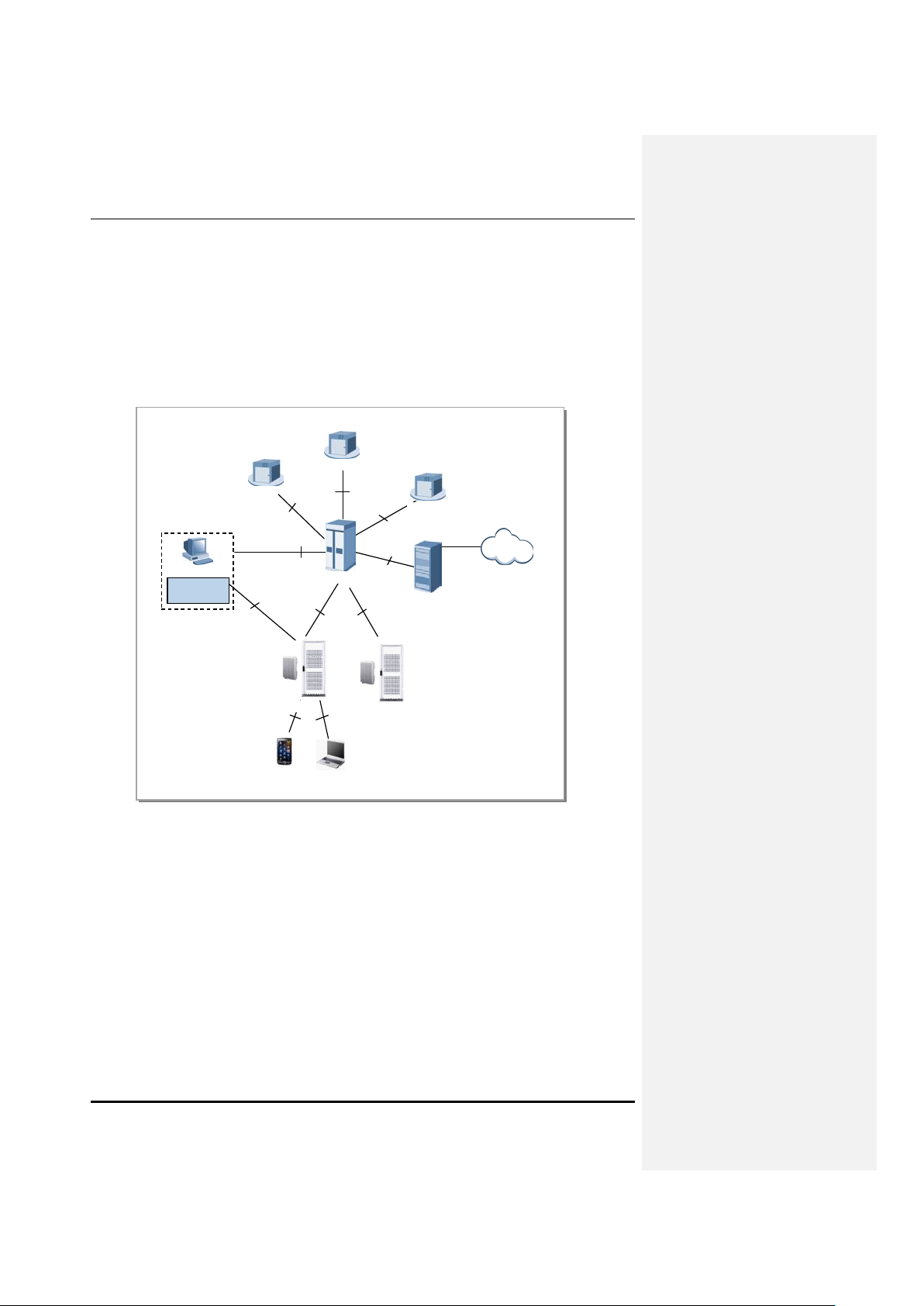
1.2.1 CDMA System Network Architecture
CDMA system network of “Samsung Multi-Modal System” consists of AN(Access Networks) for
terminal access, VCN(Voice Core Network) for voice service, and PCN(Packet Core Network) for packet
data service.
AN consists of B TS, BS C( BTS con tr ol ler ), IP Netw ork, Trans port Network, and finally BSM t o manage
these components. AN communicates with VCN(MGW, MSC/MSCe) and PCN(AN-AAA, PDSN) to
provide voice/data communication service to mobile subscribers.
MSCe
ESM
BSM
MGW
A2p
Proprietary
Proprietary
Smart MBS
IS2000,
IS856
UE
UE
BSC
A1p
A12
,A10,A11
Smart MBS
AN-AAA
Internet
PDSN
Figure 1.3 CDMA Network Architecture of Samsung Multi-Modal System
CDMA Network Architecture of Samsung Multi-Modal System(where Smart MBS is operated as CDMA
BTS) is shown in Figure 1.3. Following describes the feature per each CDMA network devices.
BTS (Base Transceiver Station)
BTS(CDMA Basestation) is a system that handles wireless interface with mobile termina ls in acc ordanc e
with CDMA2000 1X and 1xEV-DO standards. It receives data from mobile terminal and forwards it to
Core network through BSC, an d receives data fr om Core via BSC and f orwards it to m obile term in al . In
order to play a role as wire less transceiver, BS manages RF resources such as CA(Carrier Allocat ion),
Walsh. Also, it support s RF(Radio Frequency) Scheduling and Power Control Functionality.
BSC (Base Station Controller)
1-6
© SAMSUNG Electronics Co., Ltd.

Smart MBS System Description
Through var ious backhaul interfaces, BSC coordinates with multiple BTS, and provides resources that
are required for communica ting with BTS. BSC communicates with VCN to process “Voice/Circuit Data
Calls”, and coordinates with PCN to process “Packet Data Calls”. Also, it carries out
operation/maintenance func tion in conjunction with BSM. It executes RLP(Radi o Link Protocol) and
SDU(Selection and Distribution Unit) function that Hand-Off will be available for mobile terminals.
BSC also has PCF/(SC/MM) feature that “session control and mobility management function” is
executed in 1xEV-DO network.
BSM (BSS System Manager)
BSM provides “operator interface” that operators can control and manage BCS and BTS. For
Operation/Maintenance of BSC and BTS, BSM provides required commands such as
“alarm/status/performance display”, “Configuration Management”, and “Parameter Control” of the
system.
PDSN (Packet Data Serving Node) System
PDSN is a system which connects PCN to CDMA2000 1X (or 1xEV-DO), and it
enables/maintains/disables the PP P to mobile termina l. PDSN particularly carries out functionality as
FA(Foreign Agent) for HA(Home Agent) to provide mobile IP service.
AN-AAA (Access Network-Authorizatio n, Authe nticati on and Accounting)
AN-AAA is a server that performs authentication for subscribers in CDMA2000 1xEV-DO network. ANAAA executes authentication based on NAI(Network Access Identifier), and manages the “mapping
data” of IMSI and terminal NAI.
MSC (Mobile service Switching Center)/MSCe (MSC emulator)
MSC(e) is a system component which provides “switching” role in CDMA2000 network. It provides
additional services by connecting subscribers to additional equipments or other network(PSTN)
MGW (Media Gateway)
MGW is an equipment that pr ovides “b earer gatewa y function a lity” (Med ia con version and hand ling) in
a CDMA 2000 network. MGW exchanges PCM data(which is based on TDM) with PSTN, and
exchanges voice frame(which is based on IP) with BSC.
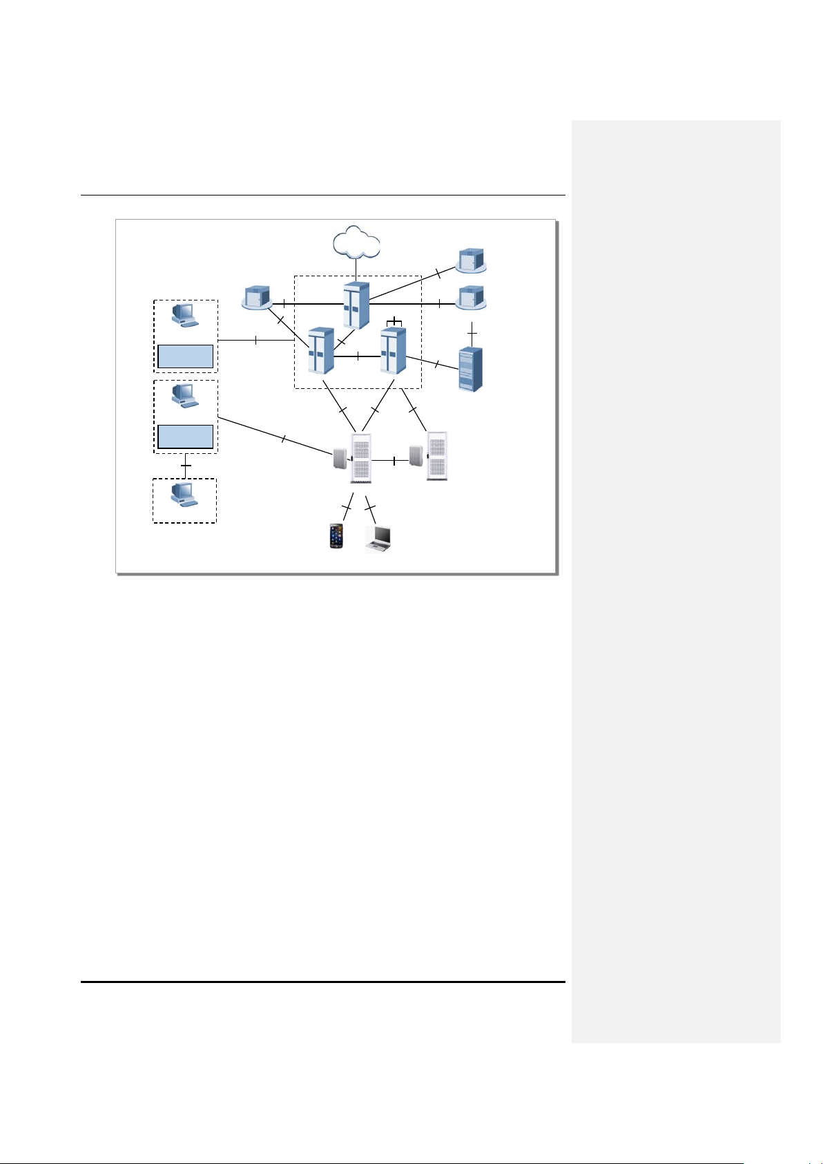
1.2.2 LTE System Network Structure
LTE netw ork of Samsu ng Multi-Modal S ystem incorporates Basestation(eN B), packet core(EPC), and
LSM/(MSS). The system consists of multiple basestations(eNB: Evolved UTRAN Node-B) and Gateway
(EPC: Evolved Packet Core, MME, S-GW/P-GW), and provides functionality for UE to connect to
external network.
In addition, LTE system provides LTE System Manager(LSM) and Self-Optim izat ion S erver Fea ture f or
Operation/Maintenance of Basestation(eNB).
© SAMSUNG Electronics Co., Ltd.
1-7
Samsung Multi-ModalSystem Abstract
EMS
LSM-C
EPC
P -GW
O CS
P C RF
CG
P DN
HS S/SPR
MMES -GW
TL1
SNM P/FTP/U DP
X2-C
X2-U
S1
S1MME
S1-U
Gz
Gz
S5/S8
S11
S10
Gy
Gx
Sp
S6a
EMS
LSM-R
MSS
RMI
Smart MBS
Smart MBS
UE
UE
Uu
Figure 1.4 Samsung Multi-Mode System’s LTE Network Architecture
LTE network architecture of Sam sung Mu lti-Modal S ystem, wh ere the Sm art M BS is ope rate d as LTE’s
Basestation(eNB), is as s hown in the Figure 1.4, and following features ar e available for each LTE
network equipment.
eNB (Evolved UTRAN Node-B)
LTE Basestation(eNB) is a system located between UE and EPC, and it handles the packet calls b y
connecting to UE wirelessly in accordanc e with “LTE Air standard”. eNB executes various functions
including Tx/Rx of Wireless signal, Modulation/Demodulation of pac ket traffic, packet scheduling for
efficient use of RF resources, HARQ (Hybrid Automatic Repeat Request) and ARQ (Automatic Repea t
Request) process, PDCP(Pac ket Data Convergence Pr otocol) of c ompressed pac ket header, and wireless
resource control. Also, it synchronizes with EPC to execute Handover.
EPC (Evolved Packet Core)
EPC is a system between Basestation(eNB) and PDN. It incorporates MME(Mobility Management
Entity), S-GW (Serving Gateway), and PDN Gateway(P-GW).
MME handles control message via basestation(eNB) and NAS signaling protocol, and management of
mobility for terminal, management of Tracking Area List, bearer and session management.
S-GW plays role as “anchor” on sub scriber plane between 2 G, 3 G Access system, and LTE system. It
manages/modifies packet transmit layer of downlink/uplink data.
P-GW allocates IP Address to UE, plays role as “anchor” for m obi lit y between “LT E S ystem ” and “n on3GPP Access Systems”, manages billing charges for different service levels, and handles
1-8
© SAMSUNG Electronics Co., Ltd.

Smart MBS System Description
management/modification of the throughput rate.
LSM (LTE System Manager)
LSM provides a synchr onized interface for operat or that Operation/Maintenan ce can be performed for
Basestaion(eNB) by operator. It also provides Software management, configuration management,
performance management, and alarm management features.
HSS(Home Subscriber Server)
HSS is a database management system that stores the parameter and geographical data of entire
subscribers. HSS manages important data including access availability, basic service, and additional
service of the subscriber. It also performs “Rooting Feature” for subscribers receiving calls.
MSS(Master SON Server)
MSS is a higher node of Local SON server. It synchronizes with Local SON Server to optimize the
synchronization in regards to Multi-LSM. MSS is a functi on that is comp atible with the operator O SS,
and the availability of this function will be decided after discussion with operator.
PCRF(Policy Charging & Rule Function)
PCRF may generate policy rule in order to apply “QoS/Billing Policies per each Service Flow”
dynamically. Or it may generate Policy rule that is applied uniformly to multiple Service Flow.
Since IP ed ge contains PCEF(Policy and Charging Enforcement Function), Po licy Rules(received from
PCRF) can be applied per each Service Flow.
OCS (Online Charging System)
If subscribers (with Online Billing information) makes call, subscriber’s billing information is
sent/received.
CG (Charging Gateway)
Stores the generated billing data, and provides billing data per each subscriber.
© SAMSUNG Electronics Co., Ltd.
1-9
Samsung Multi-ModalSystem Abstract
Abis
BSC
BTS
MAC
PHY
IP Pa cket Forwardin g
Packet Classifica tion
HARQ
L3
Voice Handler
SUA Handler
AN-AAA Client
SC/MM
A11 Handler
A10 Handler
RLP Handler
1XVoice
1xEV-DO
Paging Con troller
IP Pa cket Forwardin g
Packet Classifica tion
ARQ
1.3 Samsung Multi-Modal System Feat ure
Following is the feature supported by each mobile technology of Samsung Multi-Mod al System.
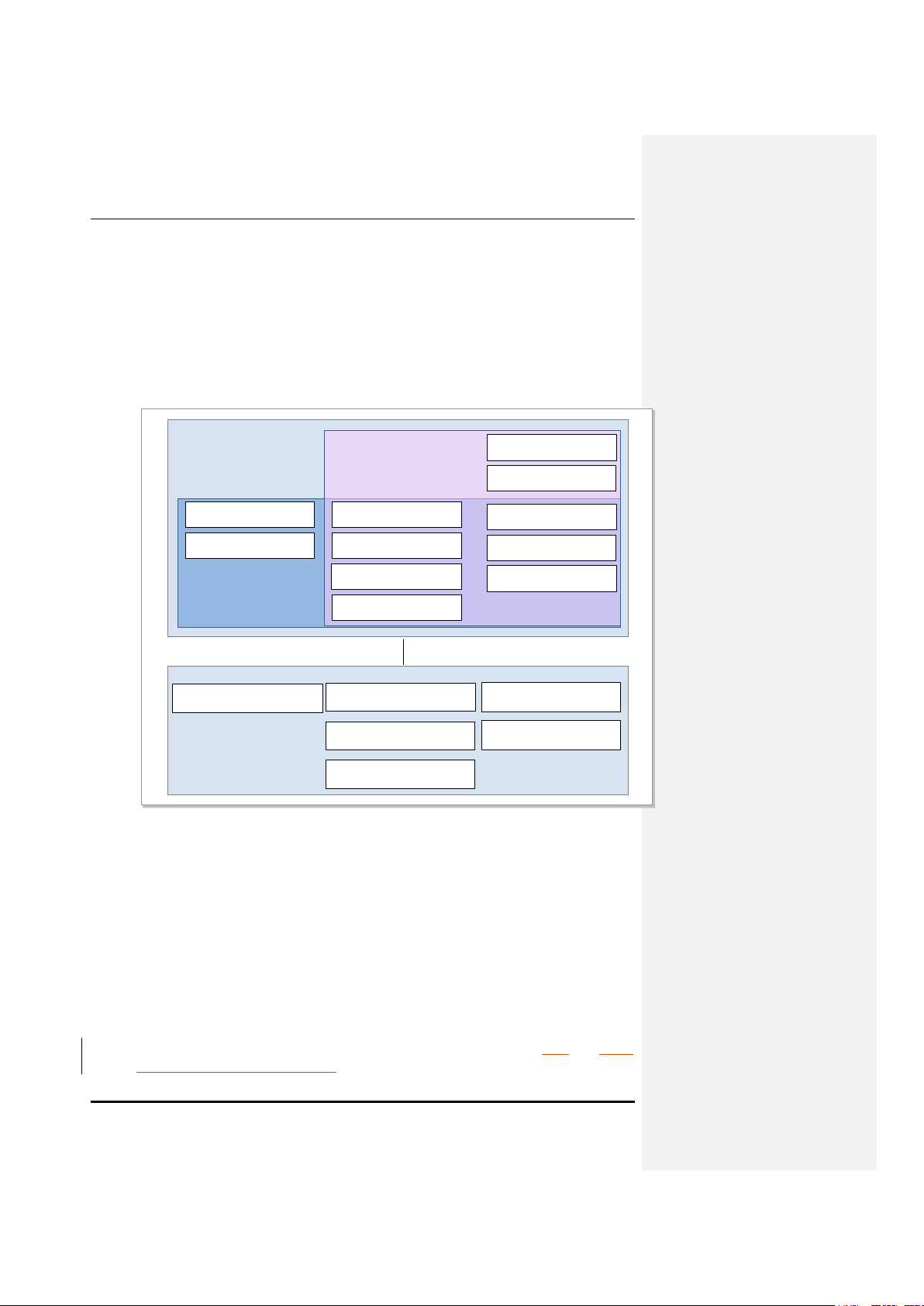
1.3.1 CDMA System Feature
Following Figure shows CDMA system(BSC, BTS)based on 1X/1xEV-DO.
Figure 1.5 CDMA System Functional Structure
BSC works wi t h voice core equipments (MSCe, MGW) to manage signaling and bearer process for voice
service. In BSC, SU A Handler is responsib le for A lp signaling with MS Ce, and Voice Handler sends the
voice bearer traffic to MGW. In addition, it works with PDSN for 1X data and 1xEV-DO data service.
A10 Handler manages the bea rer traffic of su ch data 1 X Data and 1xEV-DO Data service. A11 Handler
manages signaling for data service. RLP Handler manages ARQ feature for data communication.
For Authen tication of 1xEV-DO terminal, AN-AAA client is responsib le for synchr onization with ANAAA. SC/MM executes session control and mobility management for 1xEV-DO.
BTS is responsible for Radio Resource Control and terminal communication. Through CAI(Common Air
Interface), it provides featur es such as high speed data service, multimedia ser vice, new hand off, in
accordance with standards defined in 3GPP2 C.S0024-0_v4.0, 3GPP2 C.S0024-A_v3.0
C.S0024-B_v3.0, 3GPP2 C.S0063-B_v1.0
1-10
© SAMSUNG Electronics Co., Ltd.
, and 3GPP2

Smart MBS System Description
© SAMSUNG Electronics Co., Ltd.
1-11
Samsung Multi-ModalSystem Abstract
S1
EPC
eNB(E-UTRAN)
RRC
PDCP
RLC
MAC
PHY
MME
NAS Security
Idle State Mobility
Handling
EPS Bearer Control
S-GW
Mobility Anch oring
P-GW
UE IP address
allocation
Packet Filtering
Inter Cell RRM
RB Control
Connection Mobility Control
Radio Admission Control
eNB Measure men t Configuration & Provision
Dynamic Resource Allocation (Scheduler)
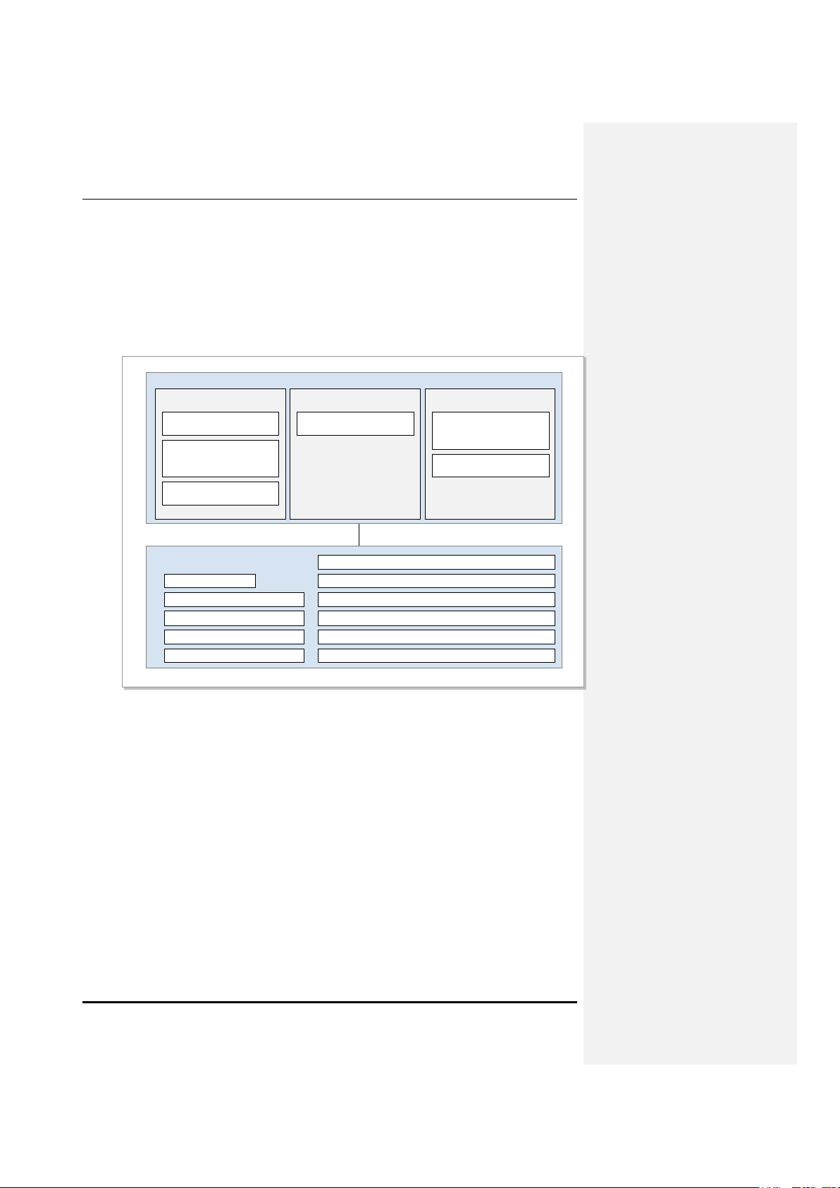
1.3.2
LTE System Feature
Following Figure shows functional separat ion between eNB, MM E, S-GW, P-GW of E-UTR AN in
accordance with 3GPP standard. Generally, eNB manages “C onnected mode” at AS(Access Stratum )
level. MME manages Idle m ode terminals in NAS(N on-Access Stratum ) level. Both S -GW and P-GW
performs “user data management” and provide the “link to foreign network”.
Following displays the functionality of eNB, MME, S-GW, and P -GW.
1-12
© SAMSUNG Electronics Co., Ltd.
Figure 1.6 Function of E-UTRAN and EPC
eNB
eNB manages E-UTRAN(Evolved UTRAN), the wireless access network of LTE system. Multiple eNB are
connected via X2 interface, and these eNB are connected to EPC(Evolved Packet Core) via S1 interface.
Wireless pr otocol layer of e NB can b e divid ed into Layer1, Layer2, and Laye r 3. Laye r 3 con tains R RC
layer, Layer 2 contains three layers(MAC layer(sublayer), RLC layer, PDCP layer) where each layer
executes an indepen dent process. RR C layer belongs to layer 3 of the wireless protocol. Generally, RRC
Layer is responsible for maint en anc e and c ontr ol of RB( Ra dio Bear er) , R RC conne ct ivity, and Exchange of
System Data. Meanwhile, PDCP layer is responsible for header compression of IP packet, security features
like “ciphering/inte grity check”, and “selecti ve transmission feature” wh ich can increase the efficiency of
“radio resource”
RLC Layer is responsible a) for s egmenta tion and reassem bly at M AC Layer for da ta which was rece ived
from PDCP layer; b) of restoring the tx failure(at lower level) via retransmission (ARQ); and c) of
reordering which can be caused because by (HARQ in MAC layer)
For each bearer, MAC Layer distributes RF res ources according to prior ity, multiplexes the data received

Smart MBS System Description
from various “Upper Logical Channels”, and performs HARQ(Hybrid ARQ).
MME(Mobility Management Entity)
MME works in conjunction with E-UTRAN(eNB) to hand le “S1-AP signalin g message ”(of SCTP ba se;
used to control connection between MME and eNB) AND “N AS S igna ling message” ( of S CTP base; us ed
to control mobility and connection between terminal and EPC.) In addition, it works in conjunction with
HSS to obtain s ubsc ribe r inf ormati on, m odific ati on, and auth enti cati on. It can w ork in conjunction with SGW, as utilizing GTP-C protoc ol, to alloc ate bearer p ath (for da ta routing a nd forward ing, releas e, and
modification)
It can also work in conjunction with SGSN(of 2G, 3G) and MSC to provide Mobility, HO, CS fallback, and
SMS service.
MME can handle mobility, idle mode UE reachability, TA list management, P-GW/S-GW selection,
authentication, and bearer management.
MME supports mobility for handover between eNB, and supports handover be tween MME. Also, SGSN
selection is supported when it hands over to 2G, 3G, or 3GPP network.
S-GW(Serving Gateway)
S-GW plays role as mobilit y anchor when h andove r is execut ed bet ween eN B, and 3GPP. As a supported
function, packet data is “Routed”, “Forwarded”. Bi lling Policy can be configured differently per each of
UE, PDN, and QCN. It can manage and modify the “packet transport layer” of the uplink/datalink data.
In addition, S-G W s uppo rts GTP a nd PMI P protocol in conjunct io n wit h MME , P-GW , and SGSN.
P-GW(PDN Gat e wa y)
P-GW can execute Billing/Bearer policy in conjunction with PCRF, and per its policy. Billing, QoS, can be
managed/modified per service level. P-GW provides Packet filtering feature per each subscriber, and
allocates IP address to each UE. P-GW can manage/modify packet transport layer of the downlink Data.
© SAMSUNG Electronics Co., Ltd.
1-13

Samsung Multi-ModalSystem Abstract
This page is intentionally left blank.
1-14
© SAMSUNG Electronics Co., Ltd.

Smart MBS System Description
Chapter 2. Smart MBS Abstract
2.1 Smart MBS System Description
Smart MBS is the Basestat ion of Sam su n g Mu lti-Modal System. It is managed by packet core (either BSC,
ACR,
or EPC), and makes call to terminal to create CDMA/WiMAX/LT E li nks.
Smart MBS interfaces with UE via either CDMA(3GPP2 CDMA2000 1X Advanced and 1xEV-DO
Rev.0/Rev.A
high speed data service and multimedia services.
In order to implement this, Sm art MBS can perform Modulation/Demodulation (for voice or packet
traffic), assign Scheduling and Wireless Bandwidth (for efficient use of RF resour ces and to guarantee
QoS), handle ARQ(Automatic Repeat request), perform ranging feature, provide connection control
feature (for sending Smart MBS information and enable/maintain/disable the call), Synchronize
BSC/ACR
By Fast Ethern et/Gigabit Ethernet backhaul, Smart MBS synchr onize the control stati on to transceive
reliable co nt rol signal and traff ic signal.
Smart MBS is separated into UADU(Universal Platform Digital Unit, an indoor DU) and the
RRH(Remote Radio He ad, a combined RF unit). UADU is mounted in the outdoor DU cabinet(along
with the rectifier) to support outdoor environment.
UADU is a digital component for 19” shelf. It can be mounted onto either indoor or outdoor 19 inch
commercial rack, and one UADU can provide the followin g maximum capacity. Based on operator ’s
setup, it can be operated as omni type or sector type.
RRH is RF component that is built into a single module. It can be mounte d onto Walls, Poles, or Stands
in outdoor environments.
Depending on Frequency bandwidth and duplexing type, RRH can be classified into following types.
(20110408)), WiMAX (IEEE 802.16) or or LTE(3 GPP LTE Rel.8/9). It provides broadband
/EPC, provides Power Control, and executes system operation management.
- CDMA 1X / EVDO : Max 128Carrier/3Sector(2Br)
Max 6Carrier/3Sector(4Br)
- WiMAX : Max 3Carrier/3Sector
- LTE (FDD) : Max 6Carrier5Carrier/3Sector
© SAMSUNG Electronics Co., Ltd.
2-1

Smart MBS Abstract
- RRH-C2: 800MHz Cellular band, 2Tx/2Rx RF path
- RRH-P4 : 1.9GHz PCS band, 4Tx/4Rx RF path
- RRH-B4 : 2.5GHz BRS band, 4Tx/4Rx RF path
Smart MBS has other features provided as below.
Common Platform DU/RRH
Digital boards of each wireless technology, to be mounted in Smart MBS, share the common DU
platform. Therefore, different boards(for multiple technology) may be mounted in a single DU, and
operator can mount up to 4 DU in outdoor DU cabinet to implement various configuration.
RRH of Smart M BS can s imultane ously s upport m ultiple techn ologies in the sam e duplex ing t ype with
the same bandwidth.
RRH(Remote Radio Head) separated from DU(Digital Unit)
In order to provide ease of installation and various network structure, Smart M BS has separated RRH
from DU. Between RRH and DU, a fiber optic ‘Baseband I/Q and C&M’ interface, based on
CPRI(Common Pub lic Radi o In terfa ce), is used to send /rec ei ve “da ta traffic s igna l” and “O AM data”. D U
and RRH gets -48VDC from rectifier inside the outdoor DU cabinet.
Provide Easy Installation
RRH integrates optic-sync component and RF signal processor, and is a sm all & light weight single
module. RRH can be mounted onto Walls, Poles, or Stands. In addition, distance between RRH and
Antenna is minimized that RF si gnal loss(cau sed b y Feeder Line) is de creased . Ther efore, it can pr ovide
improved RF performance when compared to Basestation that has Digital Unit and RF Unit altogether.
Natural Cooling Mechanism
RRH(Remote Radio Head) may be installed in outdoor environment, and its thermal-dynamic design
efficiently dissipa tes he at wi tho ut requ ir em ent of ad di ti on al c ooling mechanism. A lso, no maintenance c os t
is required for RRH cooling.
Feature for Loop-Back Test of the line between DU and RRH
In order to check functionality of the “Base-band I/Q and OAM interface” be tween DU and RRH, Sm art
MBS provides Loop-back T est.
Provides Remote Firmware Downloading
RRH may be replaced with firmware to enhance service and upgrade new features. At this time, Site visit
is not required as firmware can be downloaded from basestation operation server (such as
BSM/WSM/LSM-R). Therefore, operator can minimize the site visit, reduce the maintenanc e cost, and
easily operate the system.
Provides Monitoring Port.
Through debug port of RRH, operator can monitor the information about the unit.
2-2
© SAMSUNG Electronics Co., Ltd.
 Loading...