

Samsung SMM-BMR004 User Manual

Ver.
2600-00F46VGAA
2.0
Smart MBS RRH-P4A
Installat ion Manual

Ver.
2600-00F46VGAA
2.0
COPYRIGHT
This manual is proprietary to SAMSUNG Electronics Co., Ltd. and is protected by copyright.
No information contained herein may be copied, translated, transcribed or duplicated for any commercial
purposes or disclosed to the third party in any form without the prior written consent of SAMSUNG Electronics
Co., Ltd.
TRADEMARKS
Product names mentioned in this manual may be trademarks and/or registered trademarks of their respective
companies.
This manual should be read and used as a guideline for properly installing and operating the product.
This manual may be changed for the system improvement, standardization and other technical reasons without prior
notice.
If you need updated manuals or have any questions concerning the contents of the manuals, contact our Document
Center at the following address or Web site:
Address: Document Center 3rd Floor Jeong-bo-tong-sin-dong. Dong-Suwon P.O. Box 105, 416, Maetan-3dong
Yeongtong-gu, Suwon-si, Gyeonggi-do, Korea 442-600
Homepage: http://www.samsungdocs.com
©2012 SAMSUNG Electronics Co., Ltd. All rights reserved.

Ver.
2600-00F46VGAA
2.0
INTRODUCTION
Purpose
This manual describes procedure and method for installing Smart MBS RRH-P4A.
Document Content and Organization
This manual consists of 2 Chapters, 6 Annex and Abbreviation as follows:
Smart MBS RRH-P4A Installation Manual
CHAPTER 1. Before Installation
This chapter introduces safety rules that must be understood for installing RRH-P4A and
describes the configuration of RRH-P4A.
CHAPTER 2. Installation of RRH-P4A
This chapter describes the procedure to install RRH-P4A.
ANNEX A. Sector Antenna Installation
This annex describes sector antenna configurations and its installation requirements.
ANNEX B. Feeder Line Work
This annex describes cautions and allowed radius of curvature when installing feeder line.
ANNEX C. Assembling connector
This annex describes the procedure of assembling connector.
ANNEX D. Cleaning Optic Connector
This annex describes the procedure of cleaning the optic connector and cleaning tool.
ANNEX E. Pressure Terminal Assembly
This annex describes the procedure of assembling the pressure terminal.
© SAMSUNG Electronics Co., Ltd.
I

Ver.
INTRODUCTION
2600-00F46VGAA
2.0
ANNEX F. Standard Torque
This annex describes the standard torque when assembling the fixing materials.
ABBREVIATION
Describes the acronyms used in this manual.
Conventions
The following types of paragraphs contain special information that must be carefully read
and thoroughly understood. Such information may or may not be enclosed in a rectangular
box, separating it from the main text, but is always preceded by an icon and/or a bold title.
WARNING
Provides information or instructions that the reader should follow in order to avoid
personal injury or fatality.
CAUTION
Provides information or instructions that the reader should follow in order to avoid
a service failure or damage to the system.
CHECKPOINT
Provides the operator with checkpoints for stable system operation.
NOTE
Indicates additional information as a reference.
II
© SAMSUNG Electronics Co., Ltd.
Ver.
Smart MBS RRH-P4A Installation Manual
2600-00F46VGAA
2.0
- 2.9 Installation Test
1.0
09. 2012.
First Version
Revision Histor y
VERSION DATE OF ISSUE REMARKS
2.0 11. 2012. * Added
2.8.5 Hybrid Cable Shield Grounding Connection
* Modified
- Figure 1.3 Cabling Diagram
- Table 1.1 System Cabling
- Figure 2.15 Connecting RET cable
- Figure 2.16 RET Cable connector
- Table 2.3 RET Cable-Side Connector Pin Map
- 2.7.1 Grounding RRH-P4A
- 2.8.3 Connecting RRH-P4 Power Cable
- 2.8.4 Connecting RRH-P4 CPRI cable-Power Window
© SAMSUNG Electronics Co., Ltd.
III

Ver.
INTRODUCTION
2600-00F46VGAA
2.0
This page is intentionally left blank.
IV
© SAMSUNG Electronics Co., Ltd.

Ver.
2600-00F46VGAA
2.0
SAFETY CONCERNS
The purpose of the Safety Concerns section is to ensure the safety of users and prevent
property damage. Please read this document carefully for proper use.
Symbols
Caution
Indication of a general caution
Smart MBS RRH-P4A Installation Manual
Restriction
Indication for prohibiting an action for a product
Instruction
Indication for commanding a specifically required action
© SAMSUNG Electronics Co., Ltd.
V
Ver.
SAFETY CONCERNS
2600-00F46VGAA
2.0
WARNING
Warning
Power and Grounding
Watches, Rings, and Other Metallic Accessories
Do not wear accessories such as watches and rings in order to prevent electrical
Connecting Ground Cable
In cabling, the connection of cables without the connection to the ground cable
shock.
may cause the damage of the equipment or the bodily injury of the worker.
Connect the ground cable first.
Caution When Opening and Closing Power Window Cover
Make sure to turn off the breaker connected to the RRH-P4A power before
opening or closing the power window cover of the RRH-P4A.
If you open or close the power window cover when the breaker is turned on, it
may cause damage to the system, or cause an electric short circuit resulting in
severe injury.
Installation General
Caution for Laser Beam of Optical Module and Cable
The optical module and cable used in the system emit bright laser beams.
Always handle them with care as there is risk of serious injury if the eyes are
exposed to the laser beam of the optical cable.
Wearing protection gloves and goggles
Make sure to wear protection gloves and goggles to prevent damages from debris
while drilling holes in a wall or ceiling.
VI
© SAMSUNG Electronics Co., Ltd.
Ver.
Smart MBS RRH-P4A Installation Manual
2600-00F46VGAA
2.0
CAUTION
Caution
Power and Feeder line
Caution for cleaning the Power Supply
While cleaning the power supply device, take caution that the device does not
come in contact with alien bodies that may cause power failure.
Caution for installing the power cable
To maintain cable gland’s rain protection performance, 11.81 in. (300 mm) or
more interval should be kept straight. According to the radius of curvature of the
cable specification should be considered.
Caution for cutting the power cable
Cut power cable after installing power cable to RRH-P4A power terminal taking
into account the radius of curvature according to the cable specifications.
When cutting the cable first, the length difference of cable end can be occurred by
cable curvature and the power terminal may cause contact fault.
Caution When Connecting Optical Cables
Before connecting an optical cable, make sure that there is no dust or foreign
substance on the cross-section of the connector core. If there is any dust or
foreign substance, do not remove it by blowing with your mouth. Remove the dust
or foreign substance by referring to the method of cleaning optic connector.
Caution on Rain-proof Gasket Damage When Installing Window Cover
Be careful so as not to let the rain-proof gasket get damaged (broken or
incorrectly positioned). Check whether the rain-proof gasket is damaged before
closing the power window cover and the optic window cover.
IF the rain-proof gasket is damaged, replace the system (RRH-
P4A) with a new one.
© SAMSUNG Electronics Co., Ltd.
VII
Ver.
SAFETY CONCERNS
2600-00F46VGAA
2.0
Radius of Curvature of Feeder Line
When installing a feeder line, the radius of curvature of the sections where cables
Connection of Feeder Cable Connector
Connecting the feeder cable connector is critical process, so the qualified workers
Caution When Connecting RET Cable
Make sure to turn off the breaker connected to the RRH-P4A power of the DU
If you connect or disconnect the RET cable while the breaker is turned on, it may
bent should be larger than the allowed radius of curvature. If the radius of curvature
for the feeder line installation is less than the allowed radius of curvature, it may
affect the performance of the system.
who finished the related education should perform.
cabinet before connecting the RET cable between the antenna RET port and the
RRH-P4A RET port.
cause an electric short circuit resulting in damage to the RET function.
Installation General
Caution when losing External Power Cable Support Bracket
External Power Cable Support Bracket and two cable tie (stainless steel) for fixing
cable are enclosed in RRH-P4A package. Be careful not to lose when unpacking
package.
Managing unused port
Finish unused port of UADU by dust-cap, not making the alien substance flowed.
Finishing Cable Insertion Hole
Finishing work is required on cable insertion holes (Cable gland, Conduit and
etc.) to prevent entering of any foreign substance, external air and moisture.
- Unused cable insertion hole: Finish cable insertion hole using fishing materials
such as dust cap, rubber packing and etc.
- Cable-installed insertion hole: After installing cable, finish insertion hole using
tape, compressed sponge, rubber packing, silicon, etc. to prevent empty space.
VIII
© SAMSUNG Electronics Co., Ltd.
Ver.
Smart MBS RRH-P4A Installation Manual
2600-00F46VGAA
2.0
Caution when assembling the cable gland
Ensure that all parts of the cable gland are assembled in the correct sequence.
Incorrect assembly may result in influx of external air or moisture into the system
and may cause corrosion, system malfunction and/or critical failure of the cooling
system.
Caution when installing the cable in the cable gland
Only one cable of permitted specification (radius) should be installed in the cable
gland.
- Installing a cable of smaller radius than the permitted specification may result in
influx of external air or moisture into the system and may cause corrosion or
system malfunction.
- Installing a cable thicker than the permitted specification or installing two or
more cables in the gland may damage the gland.
Caution when loosen and tighten the Cable Gland Nut
In case of assembling the cable gland and cabling, do not loosen and tighten by
turning the cable gland body or other parts. turning the cable gland body may
cause corrosion and system failure by entering of any external air and moisture.
Checking assembly state of the unused cable gland
All components of the unused cable gland must be secured in the original factory
configuration. If the cable gland nut is fitted without the rain protection filler or the
protection cover in place, reassemble them as illustrated in ‘Figure 2.7’.
Do not work by yourself
Do not work by yourself in any key process.
Caution for cleaning the Rack
Make sure that worker does not damage installed cables while cleaning the rack.
Cautions When Connecting the CRPI Cable
Failure to observe the CPRI cable connection specified in Table 2.5 may impair
the communication between the CDMA and LTE FDD terminal.
© SAMSUNG Electronics Co., Ltd.
IX
Ver.
SAFETY CONCERNS
2600-00F46VGAA
2.0
RRH-P4A optic cable connection standard
Cable connection standard between UADU CPRI port and RRH-P4A optic port is
Connect the optic cable (Refer to the connection standard of ‘table 2.6’ and ‘table
Caution when Installing the RF antenna
To protect from lightning, the RF antenna must be installed within the shielding
- The protection angle of the lightning rod should be 45 degrees.
different according to the count (One or two) of CDMA UADU (Installed in DU
cabinet).
2.7’). Because false connection can cause the fault of call connection, be
cautious.
angle as shown below, considering the downward distance and the angle from
the tower lightning rod or the antenna pole lightning rod.
Finishing Heat Shrink Tube of a Sector Antenna
1) Insert an antenna protection plate.
2) Place the heat shrink tube on the connection point and shrink the heat shrink
tube using a heat gun.
3) Avoid aiming the heating gun toward the antenna’s body.
California USA Only
This Perchlorate warning applies only to primary CR (Manganese Dioxide)
Lithium coin cells in the product sold or distributed ONLY in California USA
‘Perchlorate Material-special handling may apply, See
www.dtsc.ca.gov/hazardouswaste/perchlorate.’
X
© SAMSUNG Electronics Co., Ltd.

Ver.
Smart MBS RRH-P4A Installation Manual
2600-00F46VGAA
2.0
TABLE OF CONTENTS
INTRODUCTION I
Purpose ...................................................................................................................................................... I
Document Content and Organization ....................................................................................................... I
Conventions ............................................................................................................................................... II
Revision History ....................................................................................................................................... III
SAFETY CONCERNS V
Symbols ..................................................................................................................................................... V
Warning ..................................................................................................................................................... VI
Caution ..................................................................................................................................................... VII
California USA Only .................................................................................................................................. X
CHAPTER 1. Before Installation 1-1
1.1 System Configuration ............................................................................................................ 1-1
1.2 Specifications......................................................................................................................... 1-3
1.3 Cabling .................................................................................................................................... 1-5
1.4 Installation Precaution .......................................................................................................... 1-7
1.5 Installation Tool .................................................................................................................... 1-12
CHAPTER 2. Installation of RRH-P4A 2-1
2.1 Installation Procedure ........................................................................................................... 2-1
2.2 Foundation Work ................................................................................................................... 2-2
2.2.1 Equipment Arrangement .......................................................................................................... 2-2
2.3 Unpacking and Transporting ................................................................................................ 2-3
2.3.1 Importing Items......................................................................................................................... 2-3
2.3.2 Unpacking Items ...................................................................................................................... 2-4
2.4 Cable Gland Assembly and Cable Installation .................................................................... 2-5
2.4.1 Cable Gland Parts .................................................................................................................... 2-6
2.4.2 Cable Gland Assembly and Cabling Procedure ..................................................................... 2-7
© SAMSUNG Electronics Co., Ltd.
XI

Ver.
TABLE OF CONTENTS
2600-00F46VGAA
2.0
2.4.3 Checking and Assembling Unused Cable Gland ................................................................ 2-10
2.5 Fixing the System ................................................................................................................. 2-11
2.5.1 Fixing Wall Mount ................................................................................................................. 2-11
2.5.2 Fixing 1 Sector Pole .............................................................................................................. 2-14
2.6 Connecting cable between RRH and Antenna ................................................................... 2-17
2.6.1 Connecting Feeder Line ....................................................................................................... 2-17
2.6.2 Connecting RET cable .......................................................................................................... 2-22
2.7 Connecting ground cable ................................................................................................... 2-25
2.7.1 Grounding RRH-P4A ............................................................................................................ 2-25
2.8 Connecting Hybrid cable ..................................................................................................... 2-28
2.8.1 Installing Hybrid cable ........................................................................................................... 2-28
2.8.2 Connecting DU Cabinet side cable ...................................................................................... 2-33
2.8.3 Connecting RRH-P4A Power Cable .................................................................................... 2-39
2.8.4 Connecting RRH-P4A CPRI cable ....................................................................................... 2-57
2.8.5 Hybrid Cable Shield Grounding Connection ....................................................................... 2-63
2.8.6 Remaining Hybrid cable ........................................................................................................ 2-65
2.9 Installation Test .................................................................................................................... 2-68
ANNEX A. Sector Antenna Installation A-1
A.1 Cautions when Installing a Sector Antenna ........................................................................ A-1
A.2 Sector Antenna Layout ......................................................................................................... A-1
A.3 Sector Antenna Installation .................................................................................................. A-2
ANNEX B. Feeder Line Work B-1
B.1 When installing the feeder, the cautions ............................................................................. B-1
B.2 Antenna Feeder Cable Ground ............................................................................................. B-4
B.3 Tower Ground Construction ................................................................................................. B-8
ANNEX C. Assembling connector C-1
C.1 RJ-45 (Shield type) ................................................................................................................ C-1
C.2 RJ-45 (Normal type) ............................................................................................................... C-3
C.3 N type-male (LMR-400) .......................................................................................................... C-4
C.4 TNC-male (LMR-400) ............................................................................................................. C-6
C.5 N type-male (1/2 in. feeder line) ............................................................................................ C-8
C.6 Din type-male (1/2 in. Feeder Line) .................................................................................... C-12
XII
© SAMSUNG Electronics Co., Ltd.

Ver.
Smart MBS RRH-P4A Installation Manual
2600-00F46VGAA
2.0
C.7 Finishing connector conne c tion with the t ape .................................................................. C-14
C.8 How to Shrink the Heat Shrink Tube .................................................................................. C-15
C.8.1 When assembling a connector to the feeder line ................................................................ C-15
C.8.2 When connecting a connector to another connector .......................................................... C-17
ANNEX D. Cleaning Optic Connector D-1
D.1 Cleaning Optic Connector ..................................................................................................... D-1
D.2 IBCTM Brand Cleaner .............................................................................................................. D-2
D.2.1 IBCTM brand type cleaner (P/N 9393) .................................................................................... D-2
ANNEX E. Pressure Terminal Assembly E-1
E.1 Preparations ........................................................................................................................... E-1
E.2 Pressure Reference Table ..................................................................................................... E-2
E.3 Assembling Pressure Terminal............................................................................................. E-5
ANNEX F. Standard Torque F-1
ABBREVIATION I
C ~ T .......................................................................................................................................................... I
U ......................................................................................................................................................... II
LIST OF FIGURES
Figure 1.1 RRH-P4A Configuration ........................................................................................ 1-1
Figure 1.2 External Interfaces of RRH-P4A ............................................................................ 1-2
Figure 1.3 Cabling Diagram.................................................................................................... 1-5
Figure 2.1 System Installation & Cable Connection Procedure .............................................. 2-1
Figure 2.2 RRH-P4A Installation Space (1 sector pole type) .................................................. 2-2
Figure 2.3 Cable Gland Parts ................................................................................................. 2-6
Figure 2.4 Cable Gland Assembly and Cable Installation Procedure (1) ................................ 2-7
Figure 2.5 Cable Gland Assembly and Cable Installation Procedure (2) ................................ 2-8
Figure 2.6 Cable Gland Assembly and Cable Installation Procedure (3) ................................ 2-9
Figure 2.7 Checking and Assembling Unused Cable Gland ................................................. 2-10
Figure 2.8 Fixing Wall Mount (1) ........................................................................................... 2-11
© SAMSUNG Electronics Co., Ltd.
XIII

Ver.
TABLE OF CONTENTS
2600-00F46VGAA
2.0
Figure 2.9 Fixing Wall Mount (2) ........................................................................................... 2-12
Figure 2.10 Fixing 1 sector pole (1) ...................................................................................... 2-14
Figure 2.11 Fixing 1 sector pole (2) ....................................................................................... 2-15
Figure 2.12 RRH-P4A Feeder Line Connection Diagram ...................................................... 2-17
Figure 2.13 Connecting RRH-P4A Feeder Line (1) ............................................................... 2-18
Figure 2.14 Connecting RRH-P4A Feeder Line (2) ............................................................... 2-19
Figure 2.15 Connecting RET cable ....................................................................................... 2-22
Figure 2.16 RET Cable Connector ........................................................................................ 2-23
Figure 2.17 Connecting RRH-P4A Ground cable .................................................................. 2-26
Figure 2.18 Installing Hybrid cable (1) .................................................................................. 2-28
Figure 2.19 Installing Hybrid cable (2) .................................................................................. 2-29
Figure 2.20 Installing Hybrid cable (3) .................................................................................. 2-30
Figure 2.21 Installing Hybrid cable (4) .................................................................................. 2-31
Figure 2.22 Peeling off the Hybrid Cable Sheath .................................................................. 2-34
Figure 2.23 Connecting Hybrid cable (1) .............................................................................. 2-35
Figure 2.24 Connecting Hybrid cable (2) .............................................................................. 2-36
Figure 2.25 Connecting Hybrid cable (3) .............................................................................. 2-37
Figure 2.26 Connecting Hybrid cable (4) .............................................................................. 2-37
Figure 2.27 Connecting RRH-P4A power cable (AWG8) (1) ................................................. 2-39
Figure 2.28 Connecting RRH-P4A power cable (AWG8) (2) ................................................. 2-40
Figure 2.29 Connecting RRH-P4A power cable (AWG8) (3) ................................................. 2-41
Figure 2.30 Connecting RRH-P4A power cable (AWG8) (3) ................................................. 2-42
Figure 2.31 Connecting RRH-P4A power cable (AWG8) (4) ................................................. 2-43
Figure 2.32 Connecting RRH-P4A power cable (AWG8) (5) ................................................. 2-44
Figure 2.33 Connecting RRH-P4A power cable (AWG8) (6) ................................................. 2-45
Figure 2.34 Connecting RRH-P4A power cable (AWG10) (1) ............................................... 2-48
Figure 2.35 Connecting RRH-P4A power cable (AWG10) (2) ............................................... 2-49
Figure 2.36 Connecting RRH-P4A power cable (AWG10) (3) ............................................... 2-50
Figure 2.37 Connecting RRH-P4A power cable (AWG10) (3) ............................................... 2-51
Figure 2.38 Connecting RRH-P4A power cable (AWG10) (4) ............................................... 2-52
Figure 2.39 Connecting RRH-P4A power cable (AWG10) (5) ............................................... 2-53
Figure 2.40 Connecting RRH-P4A power cable (AWG10) (6) ............................................... 2-54
Figure 2.41 Connecting RRH-P4A CPRI cable (1) ................................................................ 2-57
Figure 2.42 Connecting RRH-P4A CPRI cable (2) ................................................................ 2-59
Figure 2.43 Hybrid Cable Shield Grounding Connection_DU Cabinet .................................. 2-63
Figure 2.44 Hybrid Cable Shield Grounding Connection_Tower Ground Bar........................ 2-64
Figure 2.45 Remaining Hybrid cable (1) ............................................................................... 2-65
Figure 2.46 Remaining Hybrid cable (2) ............................................................................... 2-66
Figure 2.47 Remaining Hybrid cable (3) ............................................................................... 2-67
XIV
© SAMSUNG Electronics Co., Ltd.

Ver.
Smart MBS RRH-P4A Installation Manual
2600-00F46VGAA
2.0
Figure 2.48 RRH-P4A Power Section Test ........................................................................... 2-69
Figure A.1 Sector Antenna ..................................................................................................... A-2
Figure B.1 Feeder Cable Grounding (1) ................................................................................. B-4
Figure B.2 Feeder Cable Grounding (2) ................................................................................. B-5
Figure B.3 Feeder Cable Grounding (3) ................................................................................. B-6
Figure B.4 Feeder Cable Grounding (4) ................................................................................. B-7
Figure B.5 Connecting the Tower Ground Cable .................................................................... B-8
Figure C.1 Assembling the RJ-45 Connector (Shield Type) (1) .............................................. C-1
Figure C.2 Assembling the RJ-45 Connector (Shield Type) (2) .............................................. C-2
Figure C.3 Assembling the RJ-45 connector (Normal type) ................................................... C-3
Figure C.4 Assembling the N type-male connector (LMR-400) (1) ......................................... C-4
Figure C.5 Assembling the N type-male connector (LMR-400) (2) ......................................... C-5
Figure C.6 Assembling the TNC-male connector (1) .............................................................. C-6
Figure C.7 Assembling the TNC-male connector (2) .............................................................. C-7
Figure C.8 Assembling the N type-male Connector (1/2 in. Feeder Line) (1) ......................... C-8
Figure C.9 Assembling the N type-male Connector (1/2 in. Feeder Line) (2) ......................... C-9
Figure C.10 Assembling the N type-male Connector (1/2 in. Feeder Line) (3) ..................... C-10
Figure C.11 Assembling the N type-male Connector (1/2 in. Feeder Line) (4) ..................... C-11
Figure C.12 Assembling the Din type-male Connector (1/2 in. Feeder Line) (1) .................. C-12
Figure C.13 Assembling the Din type-male Connector (1/2 in. Feeder Line) (2) .................. C-13
Figure C.14 Finishing connector connection with the tape ................................................... C-14
Figure C.15 Shrinking the Heat Shrink Tube-Feeder line (1) ................................................ C-15
Figure C.16 Shrinking the Heat Shrink Tube-Feeder line (2) ................................................ C-16
Figure C.17 Shrinking the Heat Shrink Tube-Connector (1) ................................................. C-17
Figure C.18 Shrinking the Heat Shrink Tube-Connector (2) ................................................. C-18
Figure C.19 Shrinking the Heat Shrink Tube-Connector (3) ................................................. C-19
Figure D.1 Optic Connector Cleaner (IBC
TM
Brand Type Cleaner: P/N 9393) ........................ D-2
Figure D.2 Optic Module Cleaning (LC type Jack) ................................................................. D-3
Figure D.3 Optic Cable Connector Cleaning (LC type plug) ................................................... D-4
Figure D.4 Measuring the Optical Output and Connecting the Optic Connector .................... D-5
Figure E.1 Preparations.......................................................................................................... E-1
Figure E.2 Pressure Reference Drawing (Handheld Compressor) ......................................... E-2
Figure E.3 Pressure Reference Drawing (Hydraulic Press) ................................................... E-3
Figure E.4 Stripping Cable Sheath (1) .................................................................................... E-5
© SAMSUNG Electronics Co., Ltd.
XV

Ver.
TABLE OF CONTENTS
2600-00F46VGAA
2.0
Figure E.5 Stripping Cable Sheath (2) ................................................................................... E-6
Figure E.6 Fixing Pressure Terminal_Handheld Compressor (1) ........................................... E-8
Figure E.7 Fixing Pressure Terminal_Handheld Compressor (2) ........................................... E-9
Figure E.8 Fixing Pressure Terminal_Hydraulic Press (1) ..................................................... E-11
Figure E.9 Fixing Pressure Terminal_Hydraulic Press (2) .................................................... E-12
Figure E.10 Assembling Heat Shrink Tube .......................................................................... E-14
LIST OF TABLES
Table 1.1 RRH-P4A Cabling .................................................................................................... 1-6
Table 1.2 Allowed Mnimum Cable Bend Radius ..................................................................... 1-9
Table 1.3 Basic Installation Tools .......................................................................................... 1-12
Table 2.1 Recommended Distances for System Arrangement ................................................ 2-2
Table 2.2 GPS Identification Tag of Feeder line .................................................................... 2-21
Table 2.3 RET Cable-side Connector Pin Map ...................................................................... 2-23
Table 2.4 Hybrid Cable Color Map ........................................................................................ 2-36
Table 2.5 CPRI Cable connection configuration .................................................................... 2-60
Table 2.6 CPRI cable connection standard-When CDMA DU Shelf is one............................ 2-60
Table 2.7 CPRI cable connection standard-When CDMA DU Shelf is two ............................ 2-61
Table 2.8 Construction Status Checklist ................................................................................ 2-70
Table B.1 Curvature Radius of Feeder Cable for Outdoor...................................................... B-1
Table B.2 Curvature Radius of Feeder Cable for Indoor ........................................................ B-2
Table B.3 Curvature Radius of LMR-400 (Based on Times Microwave system) .................... B-2
Table B.4 Connector Connection Torque Value ...................................................................... B-3
Table B.5 TGB Installation Example ....................................................................................... B-7
Table E.1 Pressure Reference Table for Pressure Terminal ................................................... E-2
Table E.2 Compressor Specifications per Cable Thickness ................................................... E-4
Table F.1 Standard Torque Value for Fastening Bolts ............................................................. F-1
Table F.2 Brass Bolts Torque .................................................................................................. F-1
XVI
© SAMSUNG Electronics Co., Ltd.
Ver.
Smart MBS RRH-P4A Installation Manual
2600-00F46VGAA
2.0
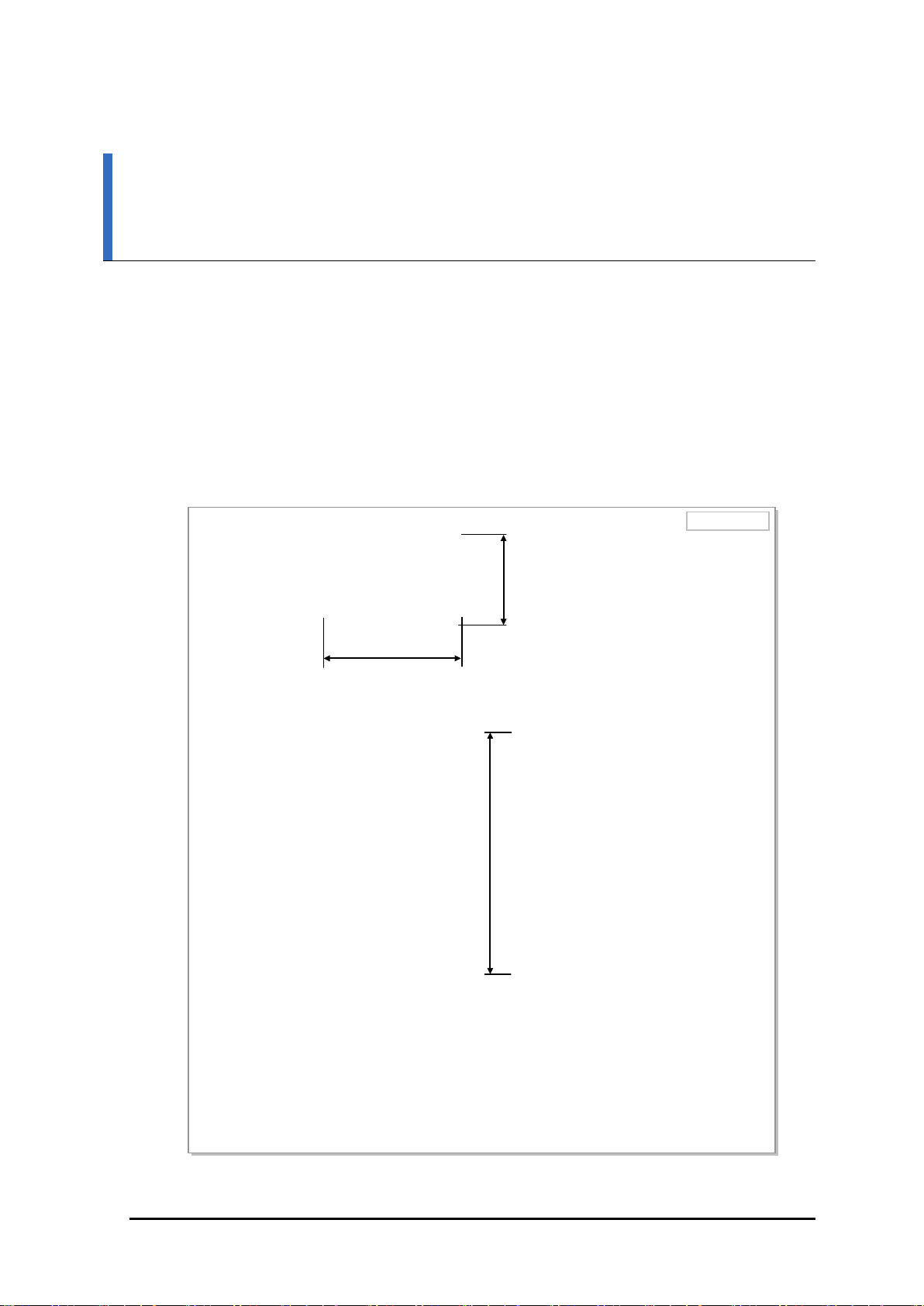
[Top View]
[Front View]
[Bottom View]
[Right View]
[Left View]
[Rear View]
23.81 (605)
8.96 (227.5)
13.78 (350)
Unit: in. (mm)
CHAPTER 1. Before Installation
1.1 System Configuration
RRH-P4A Configuration
The following shows the configuration of RRH-P4A.
© SAMSUNG Electronics Co., Ltd.
Figure 1.1 RRH-P4A Configuration
1-1
Ver.
CHAPTER 1. Before Installation
2600-00F46VGAA
2.0
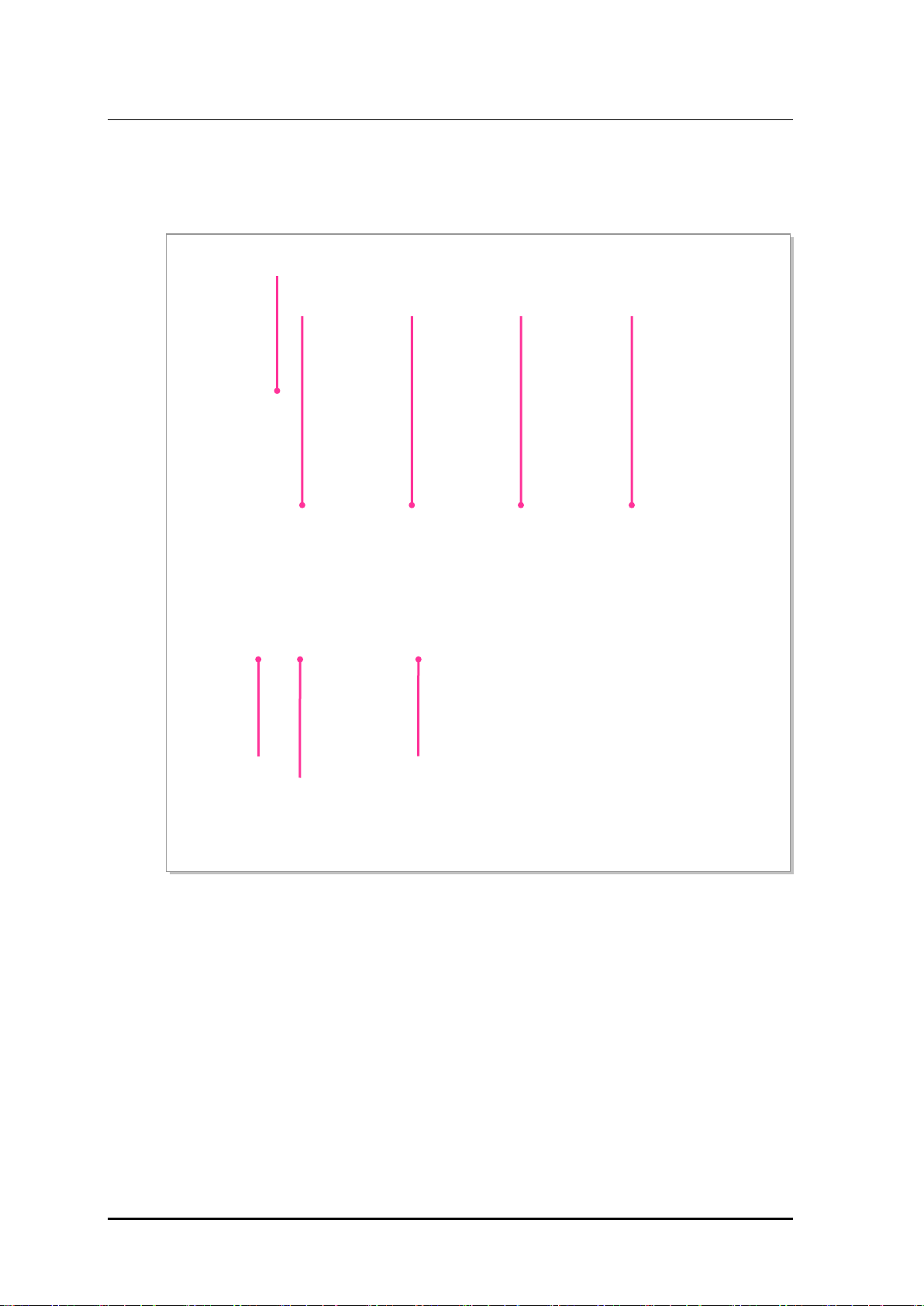
ANT 3
OPTIC
ANT 2
ANT 1
ANT 0
External Interfaces of RRH-P4A
The following shows the external interfaces of RRH-P4A.
RET Ground
POWER
[-48 V]
[Bottom View]
Figure 1.2 External Interfaces of RRH-P4A
1-2
© SAMSUNG Electronics Co., Ltd.

Ver.
Smart MBS RRH-P4A Installation Manual
2600-00F46VGAA
2.0
Air specification
CDMA/LTE FDD
- UL: 1,850~1,915 MHz
- LTE FDD: 5 MHz/10 MHz
- LTE FDD: Max. 4 Carrier @ 5 MHz
- LTE: 2T4R/4T4R
DU~RRH-P4A Interface
2.5 Gbps, CPRI 4.0 (Optic)
Input voltage
-48 V DC: -40~-56 V DC
Current consumption
20.3 A
350 × 227.5 × 605 (mm)
Weight
59.52 lb (27 kg) or less
1.2 Specifications
Capacity
The following table shows the specifications for RRH-P4A.
Item Specifications
Operating Frequency - DL: 1,930~1,995 MHz
Channel Bandwidth - CDMA: 1.25 MHz
Capacity - CDMA: Max. 8 Carrier
RF Power per Sector a) 40 W × 4Tx (Total 160 W)
Multiple Antenna - CDMA: 1T2R/2T2R/1T4R/2T4R
a) Output power at the RU antenna port. (Not external filter antenna port)
Input Power
The following table shows the power specifications for RRH-P4A. RRH-P4A complies
with UL60950 safety standard for electrical equipment.
Item Specifications
Unit Size and Weight
The following table shows the size and weight of RRH-P4A.
Item Specifications
Size (W × D × H) 13.78 × 8.96 × 23.81 (in.)
© SAMSUNG Electronics Co., Ltd.
1-3

Ver.
CHAPTER 1. Before Installation
2600-00F46VGAA
2.0
Temperaturea)
-40~131°F (-40~55°C) without solar load
The moisture content must not exceed 0.024 kg per 1 kg of air.
Altitude
0~6,000 ft (0~1,800 m)
Transportation Vibration
Noise (sound pressure level)
Max. 65 dBA at distance of 5 ft (1.5 m) and height of 3 ft (1.0 m)
(EMC)
US Federal Regulation
FCC Title47 Part27
from the front panel of the RRH-P4A.
Ambient Conditions
This section describes the operating temperature, humidity level and other ambient
conditions and related standard of RRH-P4A.
The following table shows the ambient conditions and related standard of RRH-P4A.
Item Range
Humiditya) 10~95 %
Vibration GR-63-CORE Sec.4.4
Earthquake
Office Vibration
Electromagnetic compatibility
a) Temperature and humidity are measured at 59 in. (1.5 m) above the floor and at 15.8 in. (400 mm) away
FCC Title47 Part 15 Class B
1-4
© SAMSUNG Electronics Co., Ltd.
Ver.
Smart MBS RRH-P4A Installation Manual
2600-00F46VGAA
2.0
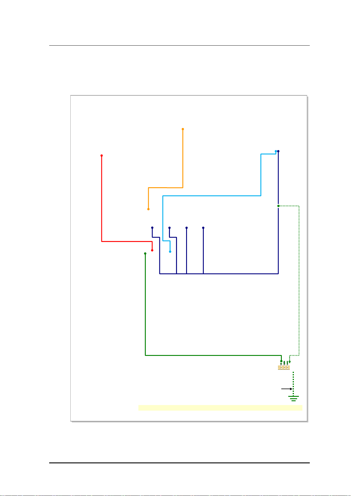
[RF Antenna]
1) TGB Ground Cable
[TGB]
(Ground Kit/7/8 in. Feeder Line or more)
※ TGB and Ground Kit are used in case of the 7/8 in. feeder line or more.
[UADU]
3) Power Cable
6) RF Cable
2) RRH-P4A Ground Cable
1.3 Cabling
The following shows the cables connected to RRH-P4A.
[Rectifier]
4) CPRI Cable
5) RET Cable
© SAMSUNG Electronics Co., Ltd.
Figure 1.3 Cabling Diagram
Feeder Line Ground Cable
1-5

Ver.
CHAPTER 1. Before Installation
2600-00F46VGAA
2.0
standard of service provider)
: AWG 8, GV 6 mm2 × 1C
: AWG 10 , 4 mm2 × 2C (or AWG8, 6 mm2 × 2C)
: Optic Cable (Single Mode)
RET
5) RET Cable Ass’y (Shield Cable)
Antenna
6) RF Cable (1/2 in. or 7/8 in. Feeder Line)
From To Cable
Table 1.1 RRH-P4A Cabling
Underground
Ground
TGB
(Tower Ground Bar)
1) TGB Ground Cable
: AWG 2, GV 25 mm2 × 1C
(However, This can be different, defending on the
RRH-P4A MGB 2) RRH-P4A Ground Cable
Rectifier 3) Power Cable
UADU 4) CPRI Cable
1-6
© SAMSUNG Electronics Co., Ltd.

Ver.
Smart MBS RRH-P4A Installation Manual
2600-00F46VGAA
2.0
1.4 In stallation Precaution
The following precaution must be observed to prevent accidents during RRH-P4A
installation.
Before Installation
Install a high voltage warning sign near the area where high voltage cable is located.
Install a restricted entry warning sign near the potential accident area.
Cover exposed areas such as junctions, ceilings, footholds etc. with safety rails or
fence off the area.
Study use of the fire alarm and the location of the fire extinguisher and how to use it.
Check the location of the nearest emergency exit.
During Installation
Cut all equipment power before installation.
Always wear protection gloves and goggles when drilling holes into the wall or ceiling.
To prevent electric shocks from metallic objects, remove all accessories such as
watches or rings.
Wearing protection gloves and goggles
Make sure to wear protection gloves and goggles to prevent damages from debris
while drilling holes in a wall or ceiling.
Watches, Rings, and Other Metallic Accessories
Do not wear accessories such as watches and rings in order to prevent electrical
shock.
Do not work by yourself
Do not work by yourself in any key process.
© SAMSUNG Electronics Co., Ltd.
1-7

Ver.
CHAPTER 1. Before Installation
2600-00F46VGAA
2.0
Cable Path Inspection
When installing a cable that connects between the rectifier, Main Ground Bar (MGB), and
backhaul device, etc. within the system, the cable path length and the cable installation
method, etc. must be inspected.
Follow these guidelines when inspecting the cabling path.
A minimum cable length must be selected provided that it does not affect the cable
installation and maintenance.
The cable must be placed in a location where it will not be damaged by external
factors. (Power line, flooding, footpaths, etc.)
In areas where the cable can be damaged by external factors, ensure that measures are
taken to prevent damages to the cable. (Cable tray, ducts, flexible pipe, etc.)
Cable Cutting
Measure the exact distance, carefully checking the route, and cut the cable using a cutting tool.
Follow these guidelines when cutting the cable.
Cut the cable to the length determined in the Cable Path Inspection step.
Use a dedicated cable cutting tool.
Cut the cable at right angles.
Be careful to keep the cable away from any moisture, iron, lead, dust or other foreign
material when cutting. Remove any foreign material attached to the cable using
solvent and a brush.
Cable Installation
Cable installation involves running the cable along the cabling path to the target connector
of the system or an auxiliary device after cable path inspection and cable cutting have been
completed.
Follow these guidelines when installing a cable.
Be careful not to damage the cable.
If the cable is damaged, cut out the damaged section before installing.
Run the cable so that it is not tangled. In particular, when installing a cable from a
horizontal section to a vertical section, be careful not to reverse the upper and lower
lines of the cable.
Always use the maximum curvature radius possible, and make sure that the minimum
curvature radius specification is complied with.
If the cable needs to be protected, use a PVC channel, spiral sleeve, flexible pipe, and
cable rack, etc.
1-8
© SAMSUNG Electronics Co., Ltd.
Ver.
Smart MBS RRH-P4A Installation Manual
2600-00F46VGAA
2.0
Bend Radius
diameter
cable
diameter
diameter
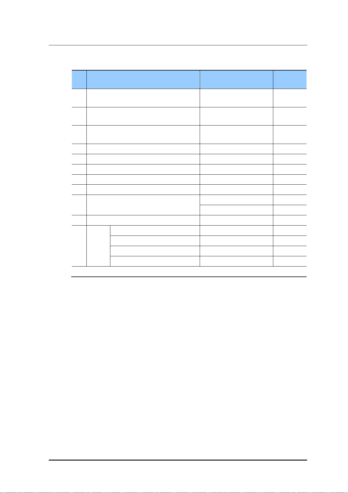
4 Pair
4
1/2 in. Feeder Line (Indoor)
1.26 in. (32 mm)
RFS, LS
5
1/2 in. Feeder Line (Outdoor)
4.92 in. (125 mm)
RFS, LS
6
7/8 in. Feeder Line (Outdoor)
9.84 in. (250 mm)
RFS, LS
7
1 1/4 in. Feeder Line (Outdoor)
14.96 in. (380 mm)
RFS, LS
8
1 5/8 in. Feeder Line (Outdoor)
19.69 in. (500 mm)
RFS, LS
1 in. (25.4 mm)
Installation
4 in. (101.6 mm)
Repeated
10
RG-316D
0.59 in. (15 mm)
-
external diameter: 0.98 in. (25 mm)
11.81 in. (300 mm)
-
external diameter: 1.06 in. (27 mm)
13.0 in. (330 mm)
-
external diameter: 1.26 in. (32 mm)
17.71 in. (450 mm)
-
* If the allowed cable bend radius is specified by the manufacturer, comply with the bend radius specified.
Table 1.2 Allowed Mnimum Cable Bend Radius
No Type
1 GV/CV/FR-8 8 times of the cable external
2 Optic Cable 20 times of the cable external
3 UTP/FTP/S-FTP Cable 4 times of the cable external
9 LMR-400
11 Hybrid
Cable
Allowed Minimum Cable
Remarks
0.6/1 KV
-
PVC/LSZH,
external diameter: 1.18 in. (30 mm) 15.35 in. (390 mm) -
Cable Binding
Cable binding involves fixing and arranging an installed cable using binding strings, cable
ties, binding lines, and ram clamps, etc.
Follow these guidelines when binding a cable.
Be careful not to damage the cable during binding.
Use appropriate cable binding tools according to the target location (indoor or outdoor,
etc.) and the use of the cable (power supply cable, optical cable, feeder line, etc.).
Do not let the cutting section of a cable tie and binding line, etc. be exposed to the
outside. This may cause damage to cables or personal injury. Make sure that the
cutting sections of cables are not exposed to the outside.
Trim the binding string so that you have about 1.97 in. (5 cm) of string left from the
knot. And insert the remaining string into the knot and make sure the knot does not
loosen.
If there is a potential danger of contact failure in a connector connection due to tension,
install the cable in the shortest distance.
© SAMSUNG Electronics Co., Ltd.
1-9

Ver.
CHAPTER 1. Before Installation
2600-00F46VGAA
2.0
Connector Attachment
Connector attachment involves assembling a connector to an installed cable or to a device
on the site.
Follow these guidelines when attaching a connector.
Make sure you are fully aware of the connector assembly method before assembling a
connector. Assemble the connector in accordance with its pin map.
Each connector has a hook to prevent its core positions from being changed.
Use a heat shrink tube at a connector connection for cables that are installed outdoor,
such as feeder lines, to prevent water leakage and corrosion from occurring at the part
exposed to the outside.
Connect each cable of the connector assembly in a straight line.
Be careful when connecting a cable not to trigger contact failure at a connector
connection due to tension.
Identification Tag Attachment
Identification tag attachment involves attaching a marker cable tie, nameplate, and label, etc. to
the both ends of a cable (connections to a connector) to identify its use and cabling path.
Marker Cable Tie
On the marker cable tie, a label can be attached.
The appearance and specification may differ depending
on the type and manufacturer
Follow these guidelines when attaching an identification tag.
When installing a cable outdoor, use relief engraving and coated labels, etc. to prevent
markings from being erased.
Since the form and attachment method for identification tags are different for each
provider, consult with the provider before attaching them.
Connecting Ground Cable
In cabling, the connection of cables without the connection to the ground cable
may cause the damage of the equipment or the bodily injury of the worker.
Connect the ground cable first.
1-10
© SAMSUNG Electronics Co., Ltd.

Ver.
Smart MBS RRH-P4A Installation Manual
2600-00F46VGAA
2.0
Cable Installation Checklist
When installing, take care not to overlap or tangle the cables; also, consider
future expansion. Install the DC power cable and data transmission cable away
from the AC power cable to prevent electromagnetic induction.
Cable Works
The cable works require knowledge for the cabling works such as cable
installation/binding.
After Installation
Cover the cable hole on the floor with a solid cover.
Remove all installation residues; clean the area.
Caution for Laser Beam of Optical Module and Cable
The optical module and cable used in the system emit bright laser beams.
Always handle them with care as there is risk of serious injury if the eyes are
exposed to the laser beam of the optical cable.
Caution for cleaning the Rack
Make sure that worker does not damage installed cables while cleaning the rack.
Caution for cleaning the Power Supply
While cleaning the power supply device, take caution that the device does not
come in contact with alien bodies that may cause power failure.
Damage Prevention
For handling devices sensitive to static electricity, be aware of the followings to avoid
damages of various board elements.
The board should be kept away from materials prone to static electricity such as plastic,
acrylic plates, paper, Styrofoam etc.
The board should be kept in a static electricity prevention storage box.
© SAMSUNG Electronics Co., Ltd.
1-11

Ver.
CHAPTER 1. Before Installation
2600-00F46VGAA
2.0
0.07~4.34 lbf·ft (1.0~60 kgf.cm)
Replaceable head
3
Torx Driver
T20 4 Nut driver set
0.24~0.39 in. (6~10 mm)
5
Hacksaw Frame/Blade
Normal/HIS
6
Level/Plumb bobs
Normal/1.10 lb (500 g)
Heating gun
122~572°F (50~300°C)
8
Solder
30~130 W
9
Power extension cable
98.42 ft (30 m)
10
Tape measure
16.4 ft (5 m)/164 ft (50 m)
11
Cable cutter
12.8 in. (325 mm)
12
Silicon gun/Silicon
Normal/Gray & Colorless
13
Spanner
0.75 in., 0.94 in., 1.42 in. (19 mm, 24 mm, 36 mm)
14
Hexagonal wrench bolt
-
15
Hoisting wire
82 ft (25 m)
Steel Cable Ties
1.5 Installation Tool
The basic tools for installation are listed in the table below. The additional tools required
for each site need to be identified and prepared during a site survey before starting
installation.
Table 1.3 Basic Installation Tools
No. Name Specification
1 Torque driver set No.0~ + No.3 (M2.6~M6 ‘+’ Driver)
2 Torque wrench set M6~M12
0.72~2.17 lbf·ft (10~30 kgf.cm),
7.23~36.15 lbf·ft (100~500 kgf.cm)
7
16 Installation Tools for Stainless
DAS-250, ties up to 0.31 in. (7.9 mm) width straps.
Precautions for use of Installation Tools
The required installation tools may vary depending on the conditions at the site.
In addition to the basic tools, a protractor, compass, GPS receiver, ladder, safety
equipment, cleaning tools etc. should also be prepared in consideration of the site
conditions.
1-12
© SAMSUNG Electronics Co., Ltd.
 Loading...