

Samsung SMM BMAA022000 User Manual
Ver.
1.0
L TE/CDMA Smart MBS
System Description

COPYRIGHT
This description is proprietary to SAMSUNG Electronics Co., Ltd. and is protected by copyright.
No information contained herein may be copied, translated, transcribed or duplicated for any commercial
purposes or disclosed to the third party in any form without the prior written consent of SAMSUNG Electronics
Co., Ltd.
TRADEMARKS
Product names mentioned in this description may be trademarks and/or registered trademarks of their
respective companies.
This description should be read and used as a guideline for properly installing and operating the product.
This description may be changed for the system improvement, standardization and other technical reasons without
prior notice.
If you need updated manuals or have an y questions concerning the contents of the manuals, contact our Document
Center at the following address or Web site:
Address: Document Center 3rd Floor Jeong-bo-tong-sin-dong. Dong-Suwon P.O. Box 105, 416, Maetan-3dong
Yeongtong-gu, Suwon-si, Gyeonggi-do, Korea 442-600
Homepage: http://www.samsungdocs.com
©2012 SAMSUNG Electronics Co., Ltd. All rights reserved.

INTRODUCTION
Purpose
This description introduces characteristics, features, and structure for Smart MBS (Multimodal Base Station), which is the Samsung Multi-Modal system.
Document Content and Organization
LTE/CDMA Smart MBS System Description
This description consists of 4 Chapters and Abbreviation as follows.
CHAPTER 1. Overview of Samsung Multi-Modal System
Samsung Multi-Modal System Introduction
Samsung Multi-Modal System Network Configuration
Samsung Multi-Modal System Feature
CHAPTER 2. Overview of Smart MBS
Smart MBS System Introduction
Smart MBS Main Feature
Smart MBS Specification
Interface between the Systems
CHAPTER 3. Smart MBS System Structure
Hardware Structure
Software Structure
CHAPTER 4. Message Flow
CDMA, LTE Call Processing Message Flow
Loading flow
ABBREVIATION
Provides definition for acronyms used in this description.
© SAMSUNG Electronics Co., Ltd. I
INTRODUCTION
Conventions
The following types of paragraphs contain special information that must be carefully read
and thoroughly understood. Such information may or may not be enclosed in a rectangular
box, separating it from the main text, but is always preceded by an icon and/or a bold title.
NOTE
Indicates additional information as a reference.
Revision History
EDITION DATE OF ISSUE REMARKS
1.0 2012. 02. First Edition
II
© SAMSUNG Electronics Co., Ltd.

LTE/CDMA Smart MBS System Description
TABLE OF CONTENTS
INTRODUCTION I
Purpose ..................................................................................................................................................I
Document Content and Organization.....................................................................................................I
Conventions........................................................................................................................................... II
Revision History.....................................................................................................................................II
CHAPTER 1. Overview of Samsung Multi-Modal System 1-1
1.1 Introduction to Samsung Multi-Modal System.................................................................... 1-1
1.2 Samsung Multi-Modal System Network Configuration.......................................................1-3
1.2.1 CDMA System Netw ork Configuration.................................................................................1-4
1.2.2 LTE System Network Configuration .....................................................................................1-7
1.3 Samsung Multi-Modal System Feature.............................................................................. 1-10
1.3.1 CDMA System Featu re.......................................................................................................1-10
1.3.2 LTE System Feature........................................................................................................... 1-11
CHAPTER 2. Smart MBS Abstract 2-1
2.1 Smart MBS System Introduction.......................................................................................... 2-1
2.1.1 CDMA System Featu re.........................................................................................................2-3
2.1.2 LTE System Feature.............................................................................................................2-3
2.2 Smart MBS Main Feature....................................................................................................... 2-7
2.2.1 Phy sical Laye r Processing Function....................................................................................2-7
2.2.2 Call Pro cessing Fun ction....................................................................................................2-11
2.2.3 IP Processing Functi on.......................................................................................................2-13
2.2.4 Operation and Maintenance Function................................................................................2-13
2.3 Specifications ...................................................................................................................... 2-16
2.4 Interface between Systems................................................................................................. 2-18
2.4.1 CDMA Interface Structure...................................................................................................2-18
2.4.2 LTE Interface Structure.......................................................................................................2-20
2.4.3 Phy sical Interface Operation Method.................................................................................2-25
© SAMSUNG Electronics Co., Ltd. III

TABLE OF CONTENTS
CHAPTER 3. Smart MBS Structure 3-1
3.1 Smart MBS Hardware Structure..............................................................................................3-1
3.1.1 Inte rnal Configuration of Sy stem (CD MA)............................................................................3-5
3.1.2 Inte rnal Configuration of Sy stem (LTE) ................................................................................3-7
3.1.3 UADU....................................................................................................................................3-9
3.1.4 LRU.....................................................................................................................................3-14
3.1.5 Pow er Device......................................................................................................................3-16
3.1.5 Environmen t Devices..........................................................................................................3-18
3.1.6 Inte rface s tructu re...............................................................................................................3-20
3.2 Smart MBS Software Structure ...........................................................................................3-24
3.2.1 CDMA Softw are Structure...................................................................................................3-24
3.2.2 LTE Software Structure.......................................................................................................3-29
CHAPTER 4. Message Flow 4-1
4.1 Call Processing Message Flow .............................................................................................4-1
4.1.1 CDMA Call Processing Message Fl ow................................................................................4-1
4.1.2 LTE Call Processing Message Flow...................................................................................4-18
4.2 Loading Flow........................................................................................................................4-29
ABBREVIATION I
A ~ C.......................................................................................................................................................I
D ~ F...................................................................................................................................................... II
G ~ M.................................................................................................................................................... III
N ~ P.....................................................................................................................................................IV
Q ~ S......................................................................................................................................................V
T ~ W....................................................................................................................................................VI
LIST OF FIGURES
Figure 1.1 Network Configuration of Samsung Multi-Modal System.......................................1-3
Figure 1.2 CDMA System Network Configuration...................................................................1-4
Figure 1.3 LTE System Network Configuration.......................................................................1-7
Figure 1.4 CDMA System Functional Structure.....................................................................1-10
Figure 1.5 Functions of E-UTRAN and EPC.........................................................................1-11
Figure 2.1 Protocol Stack between BTS and MS..................................................................2-18
Figure 2.2 Protocol Stack between BTS and BSC................................................................2-19
IV
© SAMSUNG Electronics Co., Ltd.

LTE/CDMA Smart MBS System Description/Ver.1.0
Figure 2.3 Protocol Stack between BTS and BSM............................................................... 2-19
Figure 2.4 LTE Interface Structure........................................................................................ 2-20
Figure 2.5 Protocol Stack between UE and eNB.................................................................. 2-21
Figure 2.6 Protocol Stack between eNB and EPC................................................................ 2-22
Figure 2.7 Protocol Stack between eNB and MME............................................................... 2-22
Figure 2.8 Protocol Stack between eNBs (User Plane)........................................................ 2-23
Figure 2.9 Protocol Stack between eNBs (Control Plane).................................................... 2-23
Figure 2.10 Protocol Stack between eNB and LSM.............................................................. 2-24
Figure 3.1 Smart MBS Configuration...................................................................................... 3-2
Figure 3.2 CDMA/LTE 3Sector Configuration......................................................................... 3-3
Figure 3.3 CDMA/LTE 4 Sector Configuration........................................................................ 3-4
Figure 3.4 CDMA/LTE 6 Sector Configuration........................................................................ 3-4
Figure 3.5 Internal Configuration of System (CDMA)............................................................. 3-5
Figure 3.6 Internal Configuration of System (LTE) ................................................................. 3-7
Figure 3.7 UADU Configuration.............................................................................................. 3-9
Figure 3.8 Cooling Structure of the UADU (FANM-C4)......................................................... 3-13
Figure 3.9 Power Device Configuration................................................................................ 3-16
Figure 3.10 Power Structure................................................................................................. 3-17
Figure 3.10 Configuration of Environment Devices.............................................................. 3-18
Figure 3.11 Hardware Interface structure of UADU (CDMA)................................................ 3-20
Figure 3.12 Hardware Interface structure of UADU (LTE).................................................... 3-22
Figure 3.13 Hardware Interface structure of LRU-C2........................................................... 3-23
Figure 3.14 CDMA Software Structure................................................................................. 3-24
Figure 3.15 CDMA Call Processing Software Structure........................................................ 3-24
Figure 3.16 CDMA OAM Software Structure........................................................................ 3-25
Figure 3.17 CDMA Common Software Structure.................................................................. 3-27
Figure 3.18 LTE Software Structure ..................................................................................... 3-29
Figure 4.1 1X voice call origination......................................................................................... 4-2
Figure 4.2 1X voice call termination ....................................................................................... 4-4
Figure 4.3 1X packet data call origination............................................................................... 4-6
Figure 4.4 1X packet data call termination ............................................................................. 4-7
Figure 4.5 1X voice call soft handoff ...................................................................................... 4-8
Figure 4.6 1X call release by MS............................................................................................ 4-9
Figure 4.7 1X call release by WSS....................................................................................... 4-10
Figure 4.8 1xEV-DO Session setup.......................................................................................4-11
Figure 4.9 1xEV-DO MS authentication and PPP setup....................................................... 4-12
Figure 4.10 Transition to the 1xEV-DO Dormant state ......................................................... 4-13
Figure 4.11 Transition from 1xEV-DO Dormant status to the Active state by MS ................. 4-14
© SAMSUNG Electronics Co., Ltd. V

TABLE OF CONTENTS
Figure 4.12 Transition from 1xEV-DO Dormant status to the Active state by network...........4-15
Figure 4.13 1xEV-DO softer handoff.....................................................................................4-16
Figure 4.14 1xEV-DO soft handoff........................................................................................4-17
Figure 4.15 Attach Process...................................................................................................4-18
Figure 4.16 Service Request Process by UE........................................................................4-20
Figure 4.17 Service Request Process by Network................................................................4-21
Figure 4.18 Detach Process by UE.......................................................................................4-22
Figure 4.19 Detach Process by MME ...................................................................................4-23
Figure 4.20 X2-based Handover Procedure..........................................................................4-24
Figure 4.21 S1-based Handover Procedure..........................................................................4-26
Figure 4.22 Smart MBS’ Loading Message Flow..................................................................4-30
VI
© SAMSUNG Electronics Co., Ltd.

LTE/CDMA Smart MBS System Description
CHAPTER 1. Overview of Samsung
Multi-Modal System
1.1 Introduction to Samsung Multi-Modal System
As mobile telecommunication technology has experienced rapid growth from analog
mobile telecommunication (1
Generation) to CDMA2000 (3
service is being expanded into data service.
Especially, wire/wireless hybrid service and new type mobile terminal such as smart phone
increased the demands for the high speed wireless technology. Along with the enhancement
of various mobile telecommunication networks, it is now becoming common for a single
terminal to support different mobile technologies.
Samsung Multi-Modal System is multi-mode base station that will satisfy such needs of
mobile telecommunication market by integrating voice (1X), data (1xEV-DO) and 4G
generation equipment(for example, LTE) into a single base station equipment.
Samsung Multi-Modal System mounts common Digital Unit (DU) platform, and Radio
Unit (RU) per each frequency bandwidth that operator can decide to configure it with either
single or multiple mobile technology. Samsung Multi-Modal System provides CDMA of
Frequency Division Duplex (FDD) method and LTE FDD.
In this case, Samsung Multi-Modal System supports the following telecommunication
technologies and major features.
st
Generation) to digital mobile telecommunication (2nd
rd
Generation), and into WiMAX/LTE (4th Generation), voice
Enhancement of CDMA Service Quality
When Samsung Multi-Modal system is operating in CDMA mode, it provides EV-DO
Rev0/RevA and 1X Advanced capabilities for an improved throughput and higher voice
capacity. The 2branch Rx Diversity feature provides enhanced CDMA network coverage
for the system.
CDMA2000 1X/1X Advanced
Enhanced Variable Rate Codec-B (EVRC-B), Reverse Link Interference Cancellation
(RLIC), Quasi Orthogonal Function (QOF) and New Radio Configuration (RC) are applied
© SAMSUNG Electronics Co., Ltd. 1-1

CHAPTER 1. Overview of Samsung Multi-Modal System
to Samsung Multi-Modal system based on CDMA2000 1X. Therefore, Samsung MultiModal system interworks with mobile terminal that Qualcomm Linear Interference
Cancellation (eQLIC), Mobile Receive Diversity (MRD) and New RC are applied to, can
support 1X Advanced that improves voice call capacity.
CDMA2000 1xEV-DO Rev.0/Rev.A
Samsung Multi-Modal system supports CDMA2000 1xEV-DO Rev.0/Rev.A for data
service on CDMA network.
Long Term Evolution (LTE)
Samsung Multi-Modal system supports the service based on 3GPP LTE(a.k.a. LTE).
It improves the existing 3GPP mobile telecommunication system (low data throughput, but
high in cost) to a next generation wireless network system which provides a high speed
data service with minimal cost.
Samsung Multi-Modal system supports downlink Orthogonal Frequency Division Multiple
Access (OFDMA) with either FDD, Uplink Single Carrier (SC) Frequency Division
Multiple Access (FDMA), and scalable bandwidth (for various spectrum allocation) to
provide high speed data service. Also, high-end hardware is implemented to improve system
performance and capacity that various high speed data feature/service can be provided.
Ease of Expanding 4G Service
Samsung Multi-Modal system only requires minimal board replacements and software
upgrades to provide a combined service of existing technology and 4G service from the
existing DU-RU cabinet and battery cabinet. Samsung Multi-Modal system utilizes the
existing cables, rectifiers, and batteries. The ease of 4G-installation and co-existence of
technologies will bring about a lot flexibility and efficiency for the operator in network
implementation, transition and expansion of future 4G service.
Green Solution
Samsung Multi-Modal system combines the equipment of 3G base station and the
equipment of the next generation 4G base station into a single base station, and also
contains the rectifier within the DU-RU cabinet. Samsung Multi-Modal system can reduce
the number of the equipment
Provides Efficient Backhaul Operation
Samsung Multi-Modal system provides functionality that can operate multiple
telecommunication technologies into a single physical backhaul network for reducing
backhaul expenses. In addition, it supports an efficient backhaul operation by providing a
‘per-technology’ sectional network operation by logically separating the backhaul,
minimizing traffic interference between different technologies.
1-2
© SAMSUNG Electronics Co., Ltd.
LTE/CDMA Smart MBS System Description/Ver.1.0
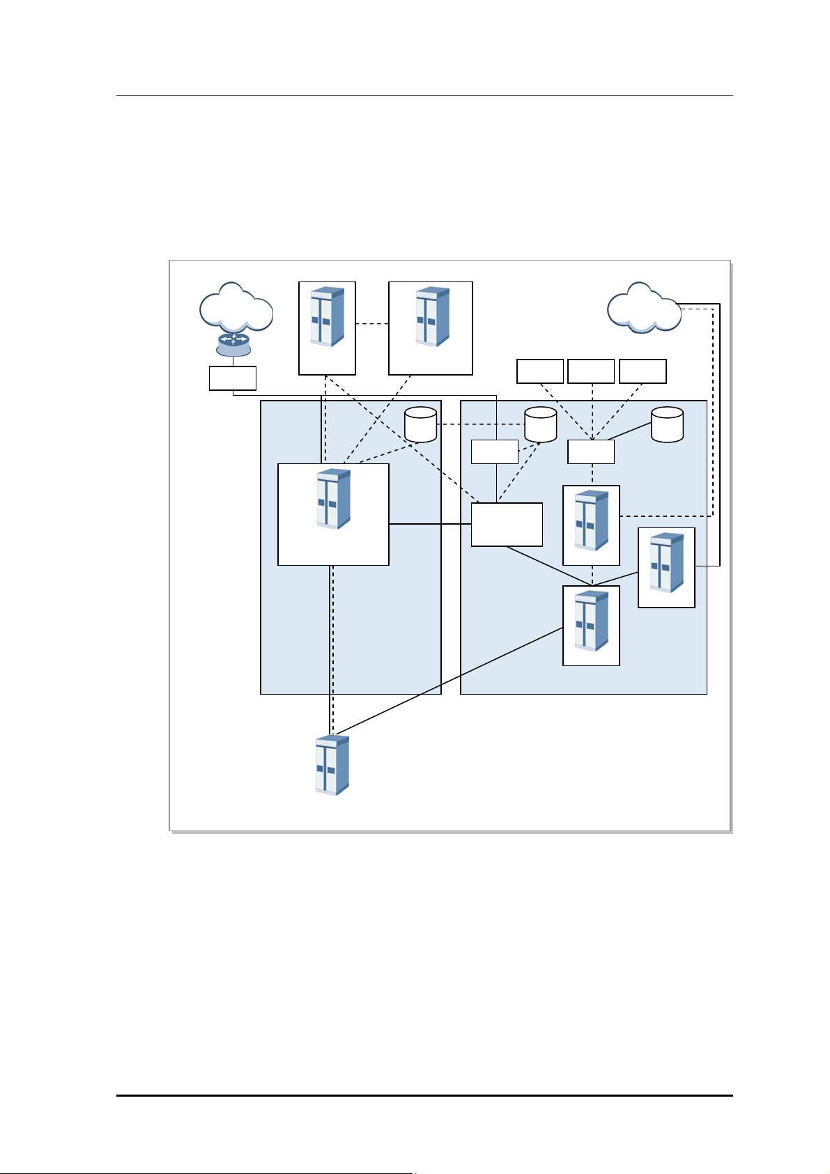
1.2 Samsung Multi-Modal System Network
Configuration
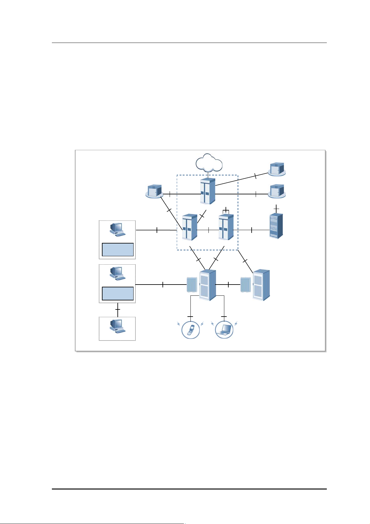
Samsung Multi-Modal system plays a role as CDMA/LTE base station in a network where
CDMA and LTE systems co-exist. Samsung Multi-Modal System is configured as follows:
PDN
DPI
Sp
PCRF
Gx
EPC
(MME/S-GW/P-GW)
S1
IMS-HSS
LTE-HSS/SPR
S6a
AAA
PMIP
RADIUS
SMS VMS SCP
MAP MAP WIN
AAA
HA
RADIUS
HSGW/
PDSN
A10/A11
CDMA LTE
STP
WSS
BSC
A1p
PSTN
MAP
A2p
HLR
MGW
Samsung Multi-Modal
System
Figure 1.1 Network Configuration of Samsung Multi-Modal System
When operating as CDMA, Samsung Multi-Modal system communicates with BSC
(CDMA controller), and operator may use BSM (EMS of CDMA) to control and manage
CDMA portion of Samsung Multi-Modal system. Likewise, when operating as LTE, it
communicates with EPC, and operator may use LSM-R (EMS of LTE) to control and
manage LTE portion of Samsung Multi-Modal system.
© SAMSUNG Electronics Co., Ltd. 1-3
CHAPTER 1. Overview of Samsung Multi-Modal System
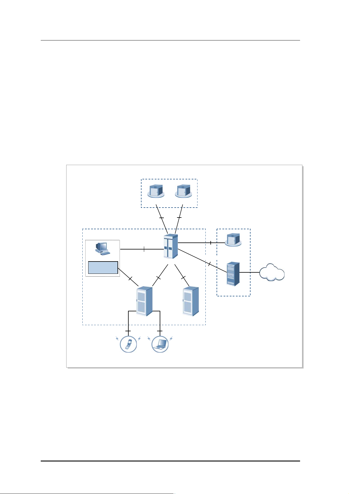
1.2.1 CDMA System Network Configuration
CDMA system network consists of Access Networks (AN) for mobile terminal access,
Voice Core Network (VCN) for voice service, and Packet Core Network (PCN) for packet
data service.
AN consists of Base Transceiver Station (BTS), Base Station Controller (BSC), and BSS
System Manager (BSM) to manage these components. AN communicates with VCN
(MGW, WSS, etc.) and PCN (AN-AAA, PDSN, etc.) to provide voice/data communication
service to mobile subscribers.
CDMA network architecture of Samsung Multi-Modal system is as follows:
VCN
WSS MGW
AN
EMS
BSM
Proprietary
Proprietary
A2p
BSC
Proprietary
A1p
Proprietary
PCN
A12
AN-AAA
A10, A11
Internet
PDSN
…
BTS
IS2000, IS856
MS
MS
Figure 1.2 CDMA Sys tem Net work C onf igura tion
BTS
1-4
© SAMSUNG Electronics Co., Ltd.

LTE/CDMA Smart MBS System Description/Ver.1.0
Base Transceiver Station (BTS)
BTS is a system that handles wireless interface with mobile terminals(Mobile Station, MS)
in accordance with CDMA2000 1X and 1xEV-DO standards as base station of CDMA.
BTS receives data from MS and forwards it to core network through BSC, and receives
data from core network via BSC and forwards it to MS. In order to play a role as wireless
transceiver, BTS manages Radio Frequency (RF) resources such as Carrier Allocation (CA),
Walsh codes.
BTS also supports RF scheduling and power control functionality.
Base Station Controller (BSC)
Through various backhaul interfaces, BSC coordinates with multiple BTS, and provides
resources that are required for communicating with BTS. BSC communicates with VCN to
process voice/circuit data calls, and coordinates with PCN to process packet data calls. It
also carries out operation/maintenance function in conjunction with BSM. It executes
Radio Link Protocol (RLP) and Selection and Distribution Unit (SDU) function aiding
handoff of MSs between BTSs. BSC also has Packet Control Function (PCF) SC/MM
feature that provides Session Control and Mobility Management function in 1xEV-DO
network.
BSS System Manager (BSM)
BSM provides operator interface that operators can control and manage BSC and BTS. For
Operation and Maintenance of BSC and BTS, BSM provides required commands such as
alarm/status/performance display, configuration management, and parameter control of the
system.
Packet Data Serving Node (PDSN) System
PDSN is a system which connects PCN to CDMA2000 1X or 1xEV-DO, and it
enables/maintains/disables the PPP to MS. PDSN particularly carries out functionality as
Foreign Agent (FA) for Home Agent (HA) to provide mobile IP service.
Access Network-Authorization, Authentication and Accounting (AN-AAA)
AN-AAA is a server that performs access network authentication for subscribers in 1xEVDO network. AN-AAA executes authentication based on Network Access Identifier (NAI),
and manages the mapping data of International Mobile Station Identity (IMSI) and MS
NAI.
Media Gateway (MGW)
MGW is an equipment that provides bearer gateway functionality (media conversion and
handling) in a CDMA network. MGW exchanges Pulse Code Modulation (PCM) data
(which is based on TDM) with PSTN, and exchanges voice frame (which is based on IP)
with BSC.
© SAMSUNG Electronics Co., Ltd. 1-5

CHAPTER 1. Overview of Samsung Multi-Modal System
Wireless Softswtich (WSS)
WSS is a system component which provides switching role in CDMA voice network. It
also provides additional services for connecting subscribers to additional equipments or
other networks (PSTN).
1-6
© SAMSUNG Electronics Co., Ltd.
LTE/CDMA Smart MBS System Description/Ver.1.0
1.2.2 LTE System Network Configuration
LTE network of Samsung Multi-Modal system incorporates base station (eNB), packet core
(EPC), LSM. The LTE system consists of multiple base stations (eNB: Evolved UTRAN
Node-B) and EPC(MME, S-GW/P-GW) provides functionality for UE to connect to
external network as subnet of PDN.
In addition, LTE system provides LSM and self-optimization function for operation and
maintenance of eEB.
LTE network architecture of Samsung Multi-Modal system is as follows:
EMS
LSM-C
EMS
LSM-R
RMI
MSS
Gz
CG
Gz
TL1
SNMP/FTP/UDP
PDN
EPC
P-GW
S-GW
S1-U
Smart MBS Smart MBS
UE
S10
S5/S8
S11 S6a
MME
S1-MME
X2-C
X2-U
Uu
UE
Gy
OCS
Gx
PCRF
Sp
HSS/SPR
S1
Figure 1.3 LTE Sy stem Net work C onfig urati on
Evolved UTRAN Node-B (eNB)
eNB is a system located between mobile terminal (User Equipment, UE) and EPC, and it
handles the packet calls by connecting to UE wirelessly in accordance with LTE air
standard. eNB executes various functions including Tx/Rx of wireless signal,
modulation/demodulation of packet traffic, packet scheduling for efficient use of RF
resources, Hybrid Automatic Repeat request (HARQ) and Automatic Repeat request
(ARQ) process, Packet Data Convergence Protocol (PDCP) of compressed packet header,
and wireless resource control.
Also, it synchronizes with EPC to execute handover.
© SAMSUNG Electronics Co., Ltd. 1-7

CHAPTER 1. Overview of Samsung Multi-Modal System
Evolved Packet Core (EPC)
EPC is a system between eNB and PDN. It incorporates MME, S-GW/P-GW.
MME: MME handles control message with eNB via Non-Access Stratum (NAS)
signaling protocol, and performs management of mobility for UE, management of
tracking area list, control plane function such as bearer and session management.
S-GW: S-GW plays role as anchor on user plane between 2G/3G access system and
LTE system. S-GW manages/processes packet transmit layer of downlink/uplink data.
P-GW: P-GW allocates IP address to UE, plays role as anchor for mobility between
LTE system and non-3GPP access systems, manages accounting for different service
levels, and handles management/modification of the throughput rate.
LTE System Manager (LSM)
LSM provides the following functions.
LTE System Manager-Radio (LSM-R)
The LSM-R provides an operator interface which the operator can use for operation
and maintenance of the eNB. It also provides functions for software management,
configuration management, performance management and fault management, and Self
Organizing Network (SON) server.
LTE System Manager-Core (LSM-C)
The LSM-C provides an operator interface which the operator can use for operation
and maintenance of the MME, S-GW and P-GW.
Home Subscriber Server (HSS)
The HSS is a database management system that stores and manages the parameters and
location information for all registered mobile subscribers. The HSS manages key data, such
as the mobile subscriber’s access capability, basic and supplementary services, and
provides a routing function to the called subscriber.
Master SON Server (MSS)
MSS is a higher node of local SON server. MSS interworks with local SON server to
optimize the interworking in regards to Multi-LSM. MSS is a function that is interworking
with the operator Operations Support System (OSS), and the availability of this optional
function will be decided after discussion with operator.
Policy Charging & Rule Function (PCRF)
The PCRF server creates policy rules to dynamically apply the QoS and accounting
policies differentiated by service flow, or creates the policy rules that can be applied
commonly to multiple service flows. The IP edge includes the Policy and Charging
Enforcement Function (PCEF), which allows application of policy rules received from the
PCRF server to each service flow.
1-8
© SAMSUNG Electronics Co., Ltd.

LTE/CDMA Smart MBS System Description/Ver.1.0
Online Charging System (OCS)
If subscribers (with online accounting information) makes call, subscriber’s accounting
information is sent/received.
Offline Charging System (OFCS)
OFCS stores the offline accounting data, and provides accounting data per each subscriber.
© SAMSUNG Electronics Co., Ltd. 1-9
CHAPTER 1. Overview of Samsung Multi-Modal System
r
Y
1.3 Samsung Multi-Modal System Feature
1.3.1 CDMA System Feature
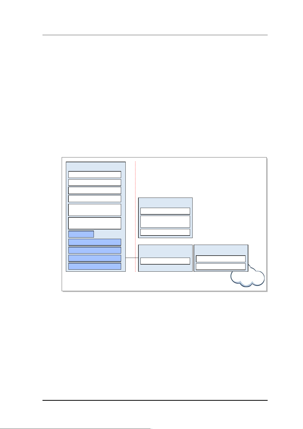
Following Figure shows CDMA system (BSC, BTS) based on 1X/1xEV-DO.
BSC
1X Voice
BTS
Voice Handle
SUA Handler
L3
Figure 1.4 CDMA Sys tem Func tiona l S tr ucture
1xEV-DO
Paging Controller
IP Packet Forwarding
Packet Classification
ARQ
Abis
HARQ
MAC
PH
AN-AAA Client
SC/MM
A11 Handler
A10 Handler
RLP Handler
IP Packet Forwarding
Packet Classification
BSC works with voice core equipments (MGW, WSS) to process signaling and bearer for
voice service.
1-10
SUA (SCCP User Adaptation) Handler: Responsible for Alp signaling with WSS
Voice Handler: Voice Handler sends the voice bearer traffic to MGW. In addition, it
works with PDSN for 1X data and 1xEV-DO data service.
A10 Handler: A10 Handler manages the bearer traffic of 1X data and 1xEV-DO data
service.
A11 Handler: A11 Handler manages signaling of data service.
RLP Handler: RLP Handler manages the ARQ functionality for data communication.
AN-AAA client: AN-AAA client interworks with AN-AAA for authentication of 1x
EV-DO terminal.
Session Control/Mobility Management (SC/MM): SC/MM provides session control
and mobility management for 1xEV-DO.
Paging Controller: Paging Controller controls the paging for incoming call.
IP Packet forwarding and Packet Classification: IP Packet forwarding and Packet
Classification function on BSC and BTS together provides the packet prioritization
and classification for implementing the QoS on Abis and air interface.
© SAMSUNG Electronics Co., Ltd.
LTE/CDMA Smart MBS System Description/Ver.1.0
BTS is responsible for radio resource control and air interface communication with MS.
Through Common Air Interface (CAI), it provides features such as high speed data service,
multimedia service, handoff procedures and QoS in accordance with standards defined in
3GPP2 C.S0024-0_v4.0 and 3GPP2 C.S0024-A_v3.0.
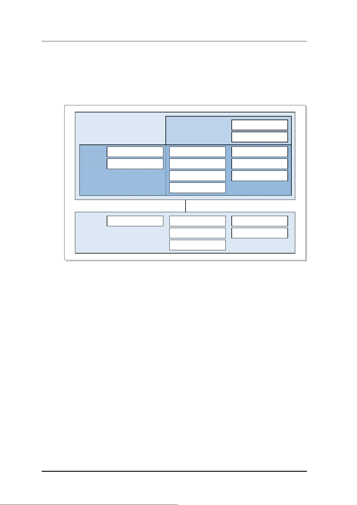
1.3.2 LTE System Feature
The eNB manages UEs which are in connected mode at the Access Stratum (AS) level.
The MME manages UEs which are in idle mode at the Non-Access Stratum (NAS) level,
and the P-GW manages user data at the NAS level as well as working with other networks.
The functional architecture of E-UTRAN eNB, MME, S-GW, and P-GW according to the
3GPP standard is shown below. The eNB is structured in layers while the EPC is not.
eNB
Inter Cell RRM
RB Control
Connection Mobility Control
Radio Admission Control
eNB Measurement
Configuration & Provision
Dynamic Resource
Allocation (Scheduler)
RRC
PDCP
RLC
MAC
PHY
S1
MME
NAS Security
Idle State Mobility
Handling
EPS Bearer Control
S-GW
Mobility Anchoring
P-GW
UE IP address allocation
Packet Filtering
E-UTRAN
EPC
Figure 1.5 Functions of E-UTRAN and EPC
Internet
eNB
The eNB serves the Evolved UTRAN (E-UTRAN), a wireless access network in the LTE
system. The eNBs are connected via the X2 interface whereas the eNB and EPC are
connected via S1 interface.
The eNB’s wireless protocol layers are divided into Layer 2 and Layer 3.
Layer 2 is subdivided into the Media Access Control (MAC) layer, Radio Link Control
(RLC) layer, and PDCP layer, each operating independently. Layer 3 has the RRC layer.
The MAC sublayer distributes wireless resources to each bearer according to its priority,
and carries out the multiplexing function and the HARQ function for the data received
© SAMSUNG Electronics Co., Ltd. 1-11

CHAPTER 1. Overview of Samsung Multi-Modal System
from the multiple upper logical channels.
The RLC layer performs the following functions.
Segmentation and reassembly on the data received from the PDCP sublayer into the
size specified by the MAC sublayer
Restoration of the transmission by resending in case of transmission failure at lower-
level layers (ARQ)
Re-ordering of the HARQ operation of the MAC sublayer
The PDCP layer carries out the following functions.
Header compression and decompression
Ciphering and deciphering of the user plane and control plane data
Integrity protection and verification of the control plane data
Data transmission of data, including serial numbers
Removing timer-based and duplicate data
The RRC layer is responsible for managing mobility in the wireless access network,
keeping and controlling the Radio Bearer (RB), managing RRC connections, and sending
system information.
Mobility Management Entity (MME)
The MME works with the E-UTRAN (eNB), handling S1 Application Protocol (S1-AP)
signaling messages in the Stream Control Transmission Protocol (SCTP) base to control
call connections between the MME and eNB as well as handling NAS signaling messages
in the SCTP base to control mobility and call connections between the UE and EPC.
The MME also works with the HSS to obtain, modify and authenticate subscriber
information, and works with the S-GW to request assignment, release and modification of
bearer paths for data routing and forwarding using the GTP-C protocol.
The MME can work with the 2G and 3G systems, SGSN, and MSC to provide mobility,
Handover (HO), Circuit Service (CS) fallback, and Short Message Service (SMS).
The MME is also responsible for managing mobility between eNBs, idle-mode UE
reachability, Tracking Area (TA) list as well as for P-GW/S-GW selection, authentication,
and bearer management.
MME supports the handover between MMEs and provides the mobility for the handover
between the eNBs.
It also supports the SGSN selection function upon handover to a 2G or 3G 3GPP network.
Serving Gateway (S-GW)
The S-GW performs the mobility anchor function upon inter-eNB handover and inter-3GPP
handover as well as routing and forwarding of packet data. The S-GW allows the operator
to set a different charging policy by UE, PDN or QCI, and manages the packet transport
layer for uplink/downlink data. The S-GW also works with the MME, P-GW, and SGSN to
support the GPRS Tunneling Protocol (GTP) and Proxy Mobile IP (PMIP).
1-12
© SAMSUNG Electronics Co., Ltd.

LTE/CDMA Smart MBS System Description/Ver.1.0
PDN Gateway (P-GW)
The P-GW works with PCRF to carry out charging and bearer policies, and manage the
charging and transmission rate based on the service level. It also provides packet filtering
per subscriber, assigns IP addresses to UEs, and manages the packet transmission layer of
the downlink data.
© SAMSUNG Electronics Co., Ltd. 1-13

CHAPTER 1. Overview of Samsung Multi-Modal System
This page is intentionally left blank.
1-14
© SAMSUNG Electronics Co., Ltd.

LTE/CDMA Smart MBS System Description
CHAPTER 2. Smart MBS Abstract
2.1 Smart MBS System Introduction
Smart MBS is the Samsung Multi-Modal system. It is managed by packet core (BSC, EPC),
and makes call to terminal to create CDMA/LTE links. It is controlled by the BSC(CDMA),
DPC(LTE)for connecting CDMA/LTE calls to the mobile terminal.
To this end, the Smart MBS provides the following functions:
modulation/demodulation of packet traffic signal, scheduling and radio bandwidth
allocation to manage air resources efficiently and ensure Quality of Service (QoS),
Automatic Repeat request (ARQ) processing, ranging function, connection control function
to transmit the information on the Smart MBS and set/hold/disconnect the packet call
connection, handover control, control station such as BSC/EPC interface function, power
control function and system operation management function.
The Smart MBS securely and rapidly transmits various control signals and traffic signals
by interfacing with the BSC/EPC via the Fast Ethernet/Gigabit Ethernet backhaul.
Physically, the Smart MBS consists of an Universal platform type A Digital Unit (UADU),
which is a DU, and Local Radio Unit (LRU), which is a combined RF unit. UADU and
LRU are mounted on the outdoor cabinet with rectifier.
UADU is a digital part, which is a type of 19 in. shelf. It can be mounted onto outdoor 19
inch commercial rack, and one UADU can provide the following maximum capacity.
Based on operator’s setup, it can be operated as omni type or sector type.
CDMA 1X/EV-DO
1X : 2 Carrier/3 Sector(2br)
1xEV-DO : 2 Carrier/3 Sector(2br)
LTE: 5 MHz 1 Carrier/6 Sector
LRU cab be operated as follows as RF part.
Advanced Wireless Services (AWS) band, 2Tx/2Rx RF path
© SAMSUNG Electronics Co., Ltd. 2-1

CHAPTER 2. Smart MBS Abstract
Smart MBS also provided the following features:
Common Platform
Digital boards of each wireless technology, to be mounted in Smart MBS, share the
common DU platform. Therefore, different boards (for multiple technologies) may be
mounted in a single DU, and operator can mount up to 2 UADUs in outdoor cabinet to
implement various configurations.
LRU of Smart MBS can simultaneously support multiple technologies in the same
duplexing type with the same bandwidth.
Loopback Test
Smart MBS provides the loopback test function to check whether communication is normal
on the baseband I/Q interface line between the UADU and LRU.
Remote Firmware Downloading
The operator can upgrade the LRU and its service by replacing its firmware. Without
visiting the field station, the operator can download firmware to the LRU remotely using a
simple command from the BSM/LSM-R. In this way, operators can minimize the number
of visits to the field station, reducing maintenance costs and allowing the system to be
operated with greater ease.
Monitoring Port
Operators can monitor the information for an LRU using its debug port.
Smooth Migration
The UADU of the Smart MBS supports migration from CDMA to 4G mobile
communication such as LTE by adding traffic processor card/channel cards and upgrading
the software.
The LRU of the Smart MBS, on the other hand, only requires software upgrade for
evolving into 4G mobile communication in the same frequency range or even simultaneous
operation of 3G and 4G mobile communications.
2-2
© SAMSUNG Electronics Co., Ltd.

LTE/CDMA Smart MBS System Description/Ver.1.0
2.1.1 CDMA System Feature
Support for 1X Advanced
Smart MBS supports 1X Advanced to improve voice call capacity and data rate. For this,
1X Advanced applies EVRC-B, RLIC, QOF, New RC, QLIC, MRD, etc.
Tx/RX Diversity Support
LRU of Smart MBS supports Time Division Transmit Diversity (TDTD) that transmit the
output of CDMA modem(1Tx) to RF path of 2Tx to improve Tx performance on option.
Also, the LRU support 2brach Rx diversity to improve Rx performance that provides 2 Rx
path for each sector.
2.1.2 LTE System Feature
OFDMA/SC-FDMA Technology
Smart MBS can handle downlink OFDMA/uplink SC-FDMA channel processing that
supports the Physical Layer of LTE standard.
Downlink OFDMA can use sub-carrier, which are assigned to each subscriber, to
simultaneously send data to multiple users. Also, in accordance with the requested data
transfer rate, it can assign single (or multiple) sub-carrier to particular subscriber for data
transmission. Also, when entire sub-carriers are shared by multiple subscribers, OFDMA
can dynamically determine well-matched sub-carrier for each subscriber, so that resource
can be assigned efficiently to enhance data throughput.
Uplink SC-FDMA is basically similar to Mod/Demodulation algorithm of OFDMA.
However, Discrete Fourier Transform (DFT) process is handled per each subscriber during
Tx Modulation, then on contrary, Inverse Discrete Fourier Transform (IDFT) process is
handled during Demodulation to minimize potential Peak to Average Power Ratio (PAPR)
that can occur during the transmission. Also it is responsible for assigning the particular
frequency resource to particular subscriber continuously. As a result, it will reduce the
power that is dissipated by terminal.
Support for Broadband Channel Bandwidth
Smart MBS provides multiple bandwidth of 5 MHz, 10 MHz and high speed/high capacity
packet service.
Support for Multiple Input Multiple Output (MIMO)
Smart MBS uses multi antenna to support 2Tx/2Rx MIMO. MIMO has following
algorithms.
Space Frequency Block Coding (SFBC)-Downlink
Increases Link Reliability
This technology implements Space Time Block Coding (STBC) on frequency
domain rather than time domain.
2 Tx Case: STBC (Alamouti codes) algorithm is used.
4 Tx Case: SFBC and Frequency Switched Transmit Diversity (FSTD) are used
© SAMSUNG Electronics Co., Ltd. 2-3

CHAPTER 2. Smart MBS Abstract
together.
Spatial Multiplexing (SM)-Downlink
This algorithm sends different data to different antenna path to increase peak data rate.
(each path uses same time/frequency resource)
Single User (SU)-MIMO: This is the SM between base station and single mobile
terminal. It increases the peak data rate of a single mobile terminal.
Open-loop SM: If channel changes often, or channel information is not available
because mobile terminal travels in high speed, this is the SM algorithm that works
without Precoding Matrix Indicator (PMI) feedback.
Closed-loop SM: If channel information is available because UE travels in low
speed, this is the SM algorithm (codebook-based precoding) that works after
receiving UE’s PMI feedback from base station.
UL Transmit Antenna Selection-Uplink
This is the algorithm that indicates terminal to use 1 RF chain, 2 Tx antenna, and
which antenna to use. (Closed-loop selection of Tx antenna)
Multi-User (MU) MIMO or Collaborative MIMO-Uplink
There is no increase in peak data rate of each mobile terminal, but this algorithm
increases the total cell throughput.
2 mobile terminals transfers different data simultaneously using the same
time/frequency resource for UL
Smart MBS uses single Tx antenna, and selects two orthogonal terminals.
QoS Support
Smart MBS provides QoS for the EPS bearer/E-RAB based on the standard QCI and
operator-specific QCI of the 3GPP TS. 23.203 specifications. Detailed techniques to
provide QoS are:
QoS-based radio scheduling
The scheduler allocates resources to provide the GBR based on QoS characteristics
(resource type, priority, PDB and PLER).
The scheduler supports the Aggregate Maximum Bit Rate (AMBR) for non-GBR
bearers.
Backhaul QoS
QoS mapping between the QoS class and DSCP
IP DSCP and Ethernet COS markings are used to satisfy the carrier’s backhaul
requirements.
Transmission is controlled according to the priority by QoS classes, such as
signaling, user traffic and O & M traffic.
QoS-based CAC
The CAC algorithm accepts calls only when the requested bit rate and QoS can be satisfied.
2-4
© SAMSUNG Electronics Co., Ltd.

LTE/CDMA Smart MBS System Description/Ver.1.0
SON
SON provides functions such as self-configuration, self-establishment and self-optimization.
Self-Configuration & Self-establishment
Self-configuration and the self-establishment allow system to configure radio parameters
automatically, and to be powered up and have backbone connectivity without human
interventions. This will reduce the cost of eNB installation and management. The detailed
functions are as follows:
Self-configuration
Initial Peripheral Component Interconnect (PCI) self-configuration
Initial neighbor information self-configuration
Initial Physical Random Access Channel (PRACH) information self-configuration
Self-establishment
Auto OAM connectivity
Software and configuration data loading
Automatic S1/X2 setup
Self-Test
Self-Optimization
PCI auto-configuration
The local SON server of the LSM provides the function for allocating the initial PCI in
the self-establishment procedure of a new system, and the function for detecting a
problem automatically and setting a proper PCI when a PCI collision/confusion occurs
during operation with the adjacent cells.
Automatic Neighbor Relation (ANR) optimization
The ANR function dynamically manages the Neighbor Relation Table (NRT)
according to neighbor cells growing/degrowing reduced so as to minimize the network
operator’s efforts to maintain the optimal NRT. To maintain the optimal NRT, SON
server is required to self-configure initial NRT of each system and to detect
environmental changes during operation, such as cell growing/degrowing or new
system installation.
In other words, the ANR function updates the NRT for each eNB by automatically
recognizing the topology change such as installing or removing a new adjacent cell or
adjacent system and by adding or removing the Neighbor Relation (NR) to or from a
new adjacent cell.
Mobility robustness optimization
Based on the moment before, after, or during handover caused by mobile terminal
mobility within the system, the mobility robustness optimization function is to
improve handover performance by recognizing problems that trigger handover at the
incorrect time (e.g., too early or too late) or to the incorrect target cell and by
optimizing the handover parameters according to the causes of the problems.
RACH optimization
The RACH Optimization (RO) function can minimize the network operator’s efforts to
minimize access delay and interference by managing dynamically the parameters
related to random access. The RO function is divided into the initial RACH setting
© SAMSUNG Electronics Co., Ltd. 2-5
CHAPTER 2. Smart MBS Abstract
operation and the operation for optimizing parameters related to the RACH.
The initial RACH setting is to set the preamble signatures and the initial time
resource considering the neighbor cells.
The parameter optimization related to the RACH is to optimize the related
parameters by estimating the RACH resources, such as time resource and
subscriber transmission power required for random access that changes by time
during operation.
Load balancing
The Load balancing feature in a multi-carrier environment selects and hands over
mobile terminal from a high-loaded carrier and to a low-loaded carrier. If all carriers in
the same sector are highly loaded, it selects a low-loaded neighbor cell and the mobile
terminal in the cell edge to perform handover. The mobile terminal selection algorithm
tries to minimize the QoS degradation.
Idle UE distribution function among carriers ensures that mobile terminals are camped
in a way that they are distributed to low-loaded carriers, considering the active UE
load distribution among the carriers in the same sector.
Availability of System Features and Functions
For availability and provision schedule of the features and functions described in
this system description, please refer to separate documentations.
2-6
© SAMSUNG Electronics Co., Ltd.
LTE/CDMA Smart MBS System Description/Ver.1.0
2.2 Smart MBS Main Feature
Smart MBS is a base station that supports CDMA/LTE technology which provides physical
layer, and call processing feature. Regardless of the operated technology, IP processing
feature and operation/maintenance feature are integrated.
2.2.1 Physical Layer Processing Function
2.2.1.1 CDMA Physical Layer Processing Function
1X & 1xEV-DO
Smart MBS can be operated in 1X (voice service) mode or 1xEV-DO(data service) mode
by carrier for CDMA service.
Specification 1X 1xEV-DO
Peak data rate 153.6 kbps 3.1 Mbps
Frame Duration 20 ms 26.67 ms(DO.0)/6.67 ms(DO.A)
Traffic Channel Fundamental/Supplemental Forward and Reverse Traffic
Channels
BS Tx power Forward and Reverse Power Control Forward Full Power/Reverse
Power Control
Pilot channel Continuous pilot Burst pilot
Channel encoding Convolution & turbo code Turbo code
Modulation BPSK(Binary Phase Shift Keying),
QPSK(Quadrature Phase Shift
Keying)
BPSK~16 QAM(Quadrature
Amplitude Modulation)
Channel Encoding/Decoding
Smart MBS carries out the encoding for the downlink packet created in the upper layer by
using convolutional code and Turbo code. On the contrary, it decodes the uplink packet
received from the mobile terminal after demodulating.
Modulation/Demodulation
Smart MBS modulates for the downlink packet created in the upper layer after encoding.
On the contrary, it decodes the uplink packet received from the mobile terminal after
demodulating.
RF Scheduler
Smart MBS perform the RF scheduling function to distribute radio resource of system
efficiently and ensure the quality of system.
Call Admission Control (CAC)/Burst Operation Control (BOC)/overload control function
are performed for 1X, Proportional Fair/Round Robin/QoS schedulers are performed for
1xEV-DO.
© SAMSUNG Electronics Co., Ltd. 2-7

CHAPTER 2. Smart MBS Abstract
Power Control
For maximizing system capacity, Smart MBS controls the output power of Smart MBS and
mobile terminal to make receiving power of the mobile terminal be the equal level and
have the minimum signal-to-interference ratio.
2.2.1.2 LTE Physical Layer Processing Function
Downlink Reference Signal Generation and Transmission
Reference Signal is used for demodulation of downlink signal at mobile terminal, and also
utilized for measuring the channel characteristic for scheduling, link adaptation, and
handoff.
In case of sending Non-MBSFN (Multimedia Broadcast multicast service over a Single
Frequency Network), there are two reference signals.
Cell-specific reference signal: Cell-specific reference signals are used to measure the
quality of the channel, calculate the MIMO rank, perform MIMO precoding matrix
selection, and measure the strength of the signals for handover.
UE-specific reference signal: UE-specific reference signals are used to measure the quality
of the channel for data demodulation which is located in the PDSCH block of the specific
mobile terminal in the beamforming transmission mode.
Downlink Synchronization Signal Generation and Transmission
Synchronization signal is used by mobile terminal when obtaining the initial
synchronization before communicating with base station. It has two signals, namely
Primary Synchronization Signal (PSS) and Secondary Synchronization Signal (SSS). Cell
identity information can be identified by synchronization signal. Mobile terminal can
obtain additional information (other than cell information) via Broadcast Channel.
Synchronization signal and Broadcast channel are transmitted through the exact center of
channel bandwidth of the cell, which is 1.08 MHz band. This is to allow mobile terminal to
identify cell’s basic information such as cell ID regardless of base station’s transmission
bandwidth range.
Channel Encoding/Decoding
Smart MBS executes channel encoding/decoding function which is designed to correct the
error generated on wireless channel environment. LTE uses turbo coding and 1/3 tail-biting
convolutional coding. Turbo coding is generally used to send relatively large data of
downlink/uplink, while convolutional coding is used for control data transmission
(downlink and uplink) or used as broadcast channel.
Modulation/Demodulation
2-8
In case of downlink, Smart MBS receive data from upper layer, process it with baseband of
physical layer, and sends it out onto wireless channel. At this time, baseband signal is
modulated to higher bandwidth in order to transmit it to longer distance. Also, in case of
uplink, base station receives the data via wireless channel, demodulate it into baseband
signal, and decodes it.
© SAMSUNG Electronics Co., Ltd.
 Loading...