

Samsung SMM 2LD0581900 Users Manual
EPB
ED.
Smart MBS
System Description/Introduction

Copyright
All text and images in this document are subject to the copyright of SAMSUNG Electronics Co., Ltd.
This document may not be reproduced, distributed, or modified without the written permission of SAMSUNG
Electronics Co., Ltd.
Trademark
The marks appearing on this document are trademarks of SAMSUNG Electronics Co., Ltd, its subsidiaries,
or affiliates.
This manual should be read and used as a guideline for properly installing and operating the product.
This manual may be changed for the system improvement, standardization and other technical reasons without prior
notice.
If you need updated manuals or have an y questions concerning the contents of the manuals, contact our Document
Center at the following address or Web site:
Address: Document Center 3rd Floor Jeong-bo-tong-sin-dong. Dong-Suwon P.O. Box 105, 416, Maetan-3dong
Yeongtong-gu, Suwon-si, Gyeonggi-do, Korea 442-600
Homepage: http://www.samsungdocs.com
©2011 SAMSUNG Electronics Co., Ltd. All rights reserved.

INTRODUCTION
Smart MBS System Description
Purpose
This document introduces characteristics, features, and structure for Smart MBS Base Station of the
Samsung Multi-Modal System.
Document Content and Organization
This document consists of 4 CHAPTERS, APPENDIX, and ACRONYMS.
Chapter 1. Samsung Multimodal System Abstract
Explains the following…
Smart MBS System Introduction
Samsung Multimodal System Network Configurat ion
Samsung Multimodal System Feature
Chapter 2. Smart MBS Abstract
Explains the following…
Smart MBS System’s Characteristics
Smart MBS ‘s Main Feature
Smart MBS ‘s Specification
Operation manual on Backhaul Interface
Chapter 3. HW Architecture of Smart MBS
Explains the following…
System Internal Struct ure
UADU (Universal Platform Digital Unit)
RRH (Remote Radio Head)
Thermal Radiation Structure
© SAMSUNG Electronics Co., Ltd. I
INTRODUCTION
Chapter 4. SW Architecture of Smart MBS
Explains the following…
Smart MBS SW Structure
Loading Flow
ABBREVIATION
Provides definition for acronyms used in this document.
Conventions
Following symbols are used in this document. The information provided along with this symbol should
be familiarized for safe operation/handling of the system.
Additional Reference
Provides reference in addition to the main contents.
Reference
Revision History
Rev . Date Note
1.0 2011.06 First Edition
II © SAMSUNG Electronics Co., Ltd.

Smart MBS System Description
TABLE OF CONTENTS
INTRODUCTION I
Purpose ..................................................................................................... I
Document Content and Organization ....................................................................... I
Conventions .................................................................................................... II
Revision History ................................................................................................. II
Chapter 1. Samsung Multi-ModalSystem Abstract 1-1
1.1 Introduction to Smart MBS System........................................................................... 1-1
1.2 Samsung Multi-Modal System Network Architecture ....................................................... 1-4
1.2.1 CDMA System Network Architecture ......................................................... 1-5
1.2.2 LTE System Network Structure ................................................................ 1-6
1.3 Samsung Multi-Modal System Feature ....................................................................... 1-9
1.3.1 CDMA System Feature .......................................................................... 1-9
1.3.2 LTE System Feature ........................................................................... 1-10
Chapter 2. Smart MBS Abstract 2-1
2.1 Smart MBS System Description .............................................................................. 2-1
2.1.1 Smart MBS CDMA System Feature .............................................................. 2-3
2.1.3 Smart MBS LTE System Feature ................................................................. 2-3
2.2 Smart MBS Main Feature ..................................................................................... 2-6
2.2.1 Physical layer Processing Feature ................................................................ 2-6
2.2.2 Call Processing Feature ............................................................................ 2-9
2.2.3 IP Processing Feature ............................................................................ 2-10
2.2.4 Convenient Operation and Maintenance Feature ............................................ 2-11
2.3 Smart MBS Specification .................................................................................... 2-14
2.4 Backhaul Interface Operation ................................................................................... 2-17
Chapter 3. Smart MBS’s Hardware Structure 3-1
3.1 Internal System Architecture ...................................................................................... 3-4
3.1.1 CDMA Internal System Architecture .......................................................... 3-4
© SAMSUNG Electronics Co., Ltd. III

TABLE OF CONTENTS
3.1.2 LTE Internal System Structure ................................................................. 3-6
3.2 UADU(Universal Platform Digital Unit) .......................................................................... 3-8
3.3 RRH (Remote Radio Head) ...................................................................................... 3-14
3.4 Cooling Mechanism .............................................................................................. 3-17
3.4.1 Digital Unit (DU) ................................................................................ 3-17
3.4.2 RRH (Remote Radio Head) ................................................................... 3-17
3.5 Interface structure ................................................................................................ 3-18
Chapter 4. Smart MBS Software Architecture 4-1
4.1 Smart MBS SW Architecture ...................................................................................... 4-1
4.1.1 CDMA System Basic SW architecture ........................................................... 4-1
4.1.2 LTE System Basic SW Architecture .............................................................. 4-4
4.2 Loading Flow .................................................................................................. 4-7
ABBREVIATION I
IV © SAMSUNG Electronics Co., Ltd.

Smart MBS System Description
LIST OF FIGURES
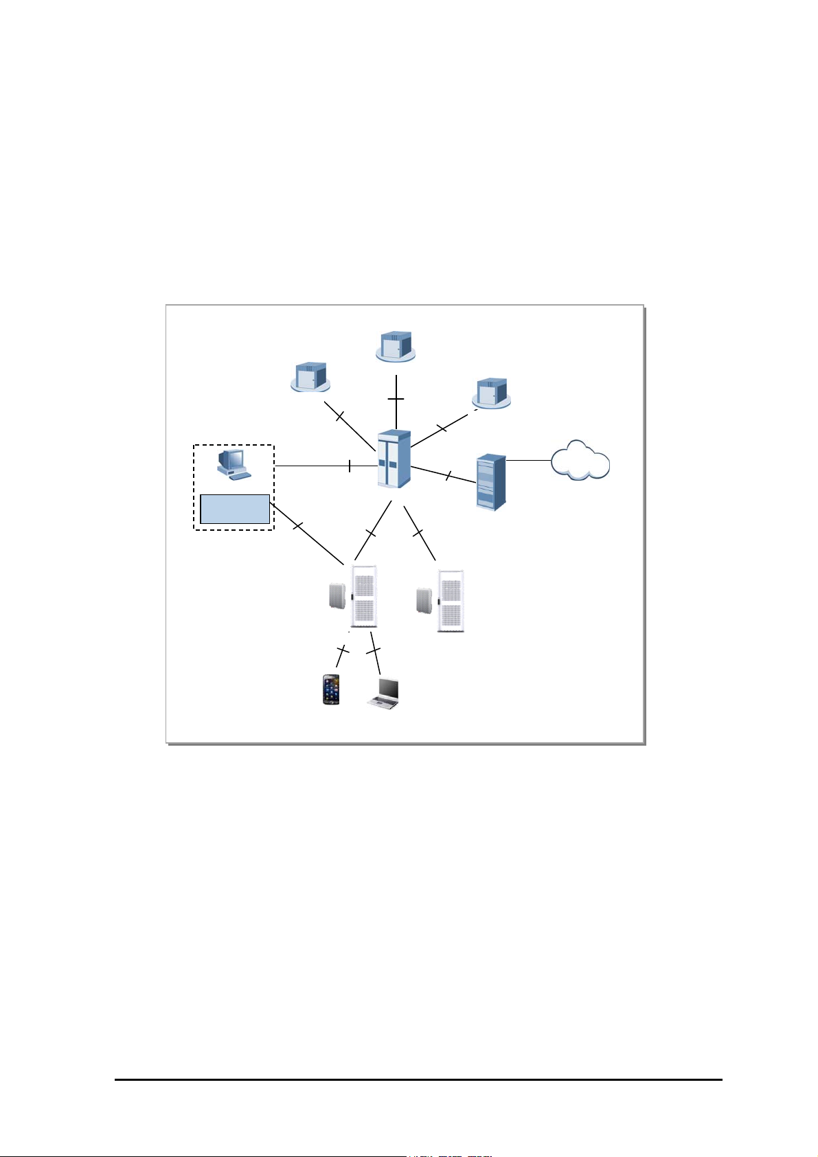
Figure 1.1 Smart MBS System Schematic .................................................................... 1-2
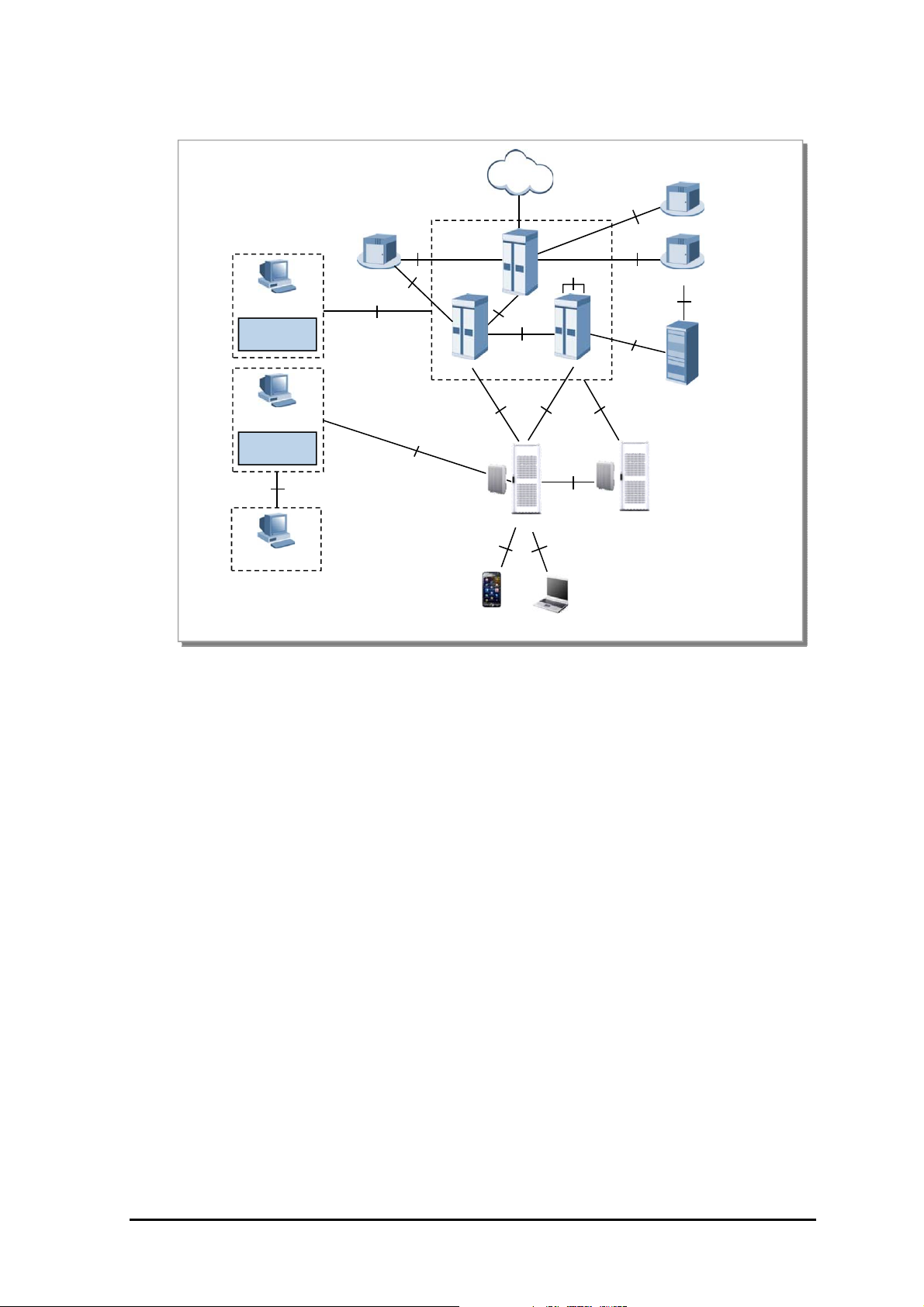
Figure 1.2 Samsung Multi-modal Network Architecture ..................................................... 1-4
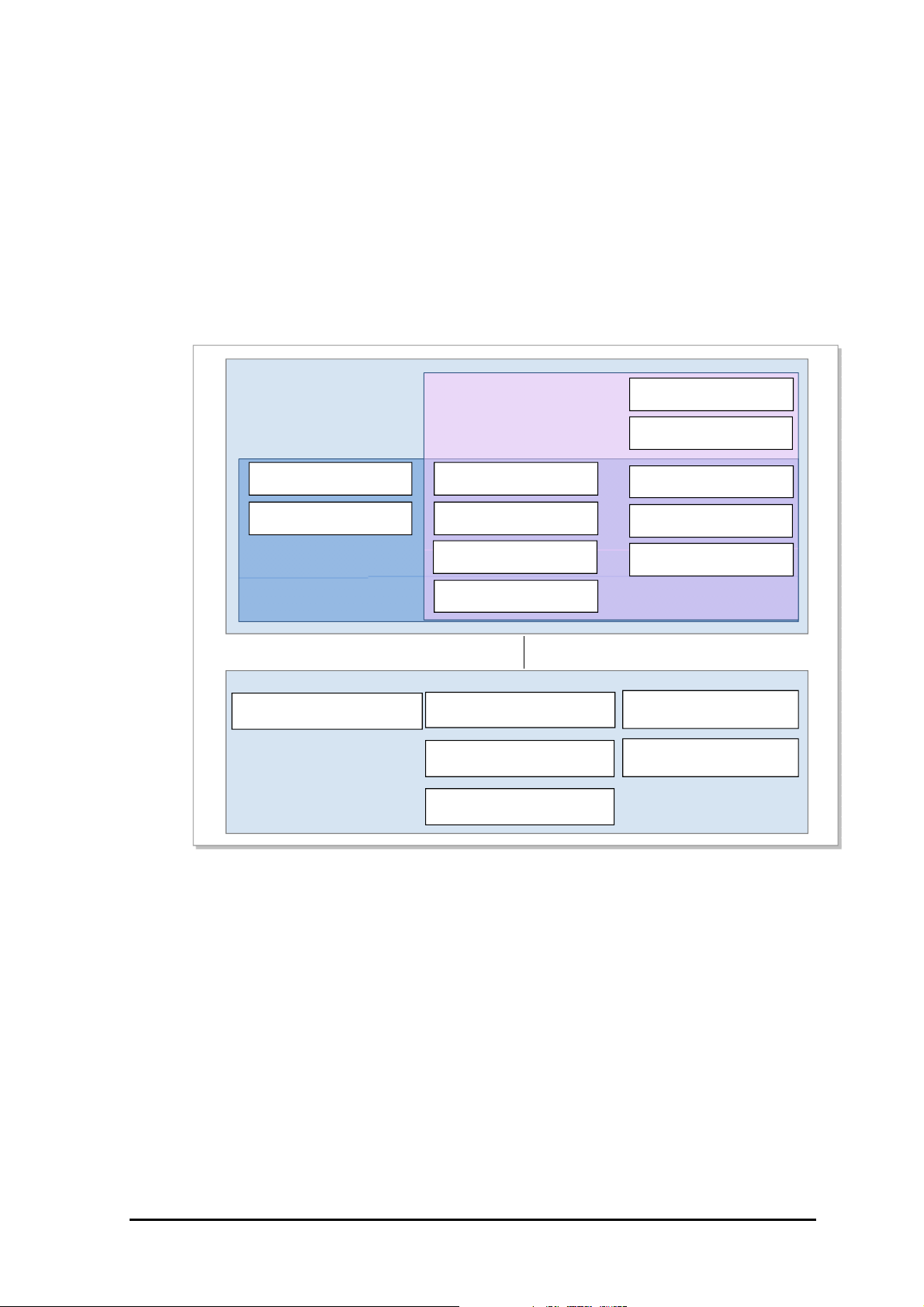
Figure 1.3 CDMA Network Architecture of Sams ung Multi-M odal S ystem ................................. 1-5
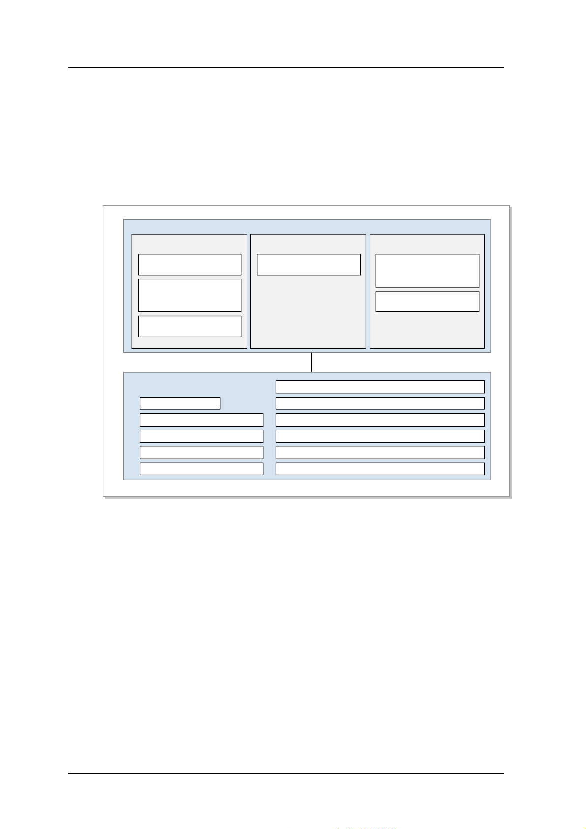
Figure 1.4 Samsung Multi-Mode System’s LTE Network Architecture ...................................... 1-7
Figure 1.5 CDMA System Functional Structure .............................................................. 1-9
Figure 1.6 Function of E-UTRAN and EPC ................................................................ 1-10
Figure 3.1 UADU Configuration - CDMA Single mode ..................................................... 3-2
Figure 3.2 UADU Configuration - L TE Single mode ......................................................... 3-2
Figure 3.3 UADU Configuration - CDMA + LTE dual mode ................................................ 3-2
Figure 3.4 RRH-C2 (800MHz) ................................................................................ 3-3
Figure 3.5 RRH-P4(1.9GHz) .................................................................................. 3-3
Figure 3.6 Smart MBS CDMA Intern al Block Diagram ...................................................... 3-4
Figure 3.7 Smart MBS LTE’s Internal Blo ck Diagra m ....................................................... 3-6
Figure 3.8 UADU Configuration - CDMA Only ........................................................... 3-12
Figure 3.9 UADU Configuration - CDMA Only(Two UADU) ............................................ 3-13
Figure 3.10 UADU Configuration - L TE Only ............................................................. 3-13
Figure 3.11 UADU Configuration - CDMA+LTE Dual Mode ............................................. 3-13
Figure 3.12 UADU Configuration - CDMA+LTE Dual Mode(Two UADU) .............................. 3-13
Figure 3.13 UADU’s FAN Structure ........................................................................ 3-17
Figure 3.14 UADU’s Cooling Mechanism .................................................................. 3-17
Figure 3.15 HW Interface structure of UADU(CDMA) .................................................... 3-18
Figure 3.16 HW Interface structure of UADU(L TE) ....................................................... 3-19
Figure 3.17 HW Interface structure of RRH-C2 ............................................................ 3-19
Figure 3.18 HW Interface structure of RRH-P4 ............................................................ 3-20
Figure 4.1 Smart MBS CDMA Softw are Architecture ....................................................... 4-1
Figure 4.2 CDMA Common Software Architecture .......................................................... 4-2
Figure 4.3 CDMA OAM Software Architecture .............................................................. 4-3
Figure 4.4 CDMA Call Pro cessing Softw are S tr ucture ....................................................... 4-3
Figure 4.5 Smart MBS LTE Software Architecture ........................................................... 4-4
Figure 4.6 Smart MBS' Loading Signal Flow ................................................................. 4-8
© SAMSUNG Electronics Co., Ltd. V

TABLE OF CONTENTS
This page is intentionally left blank.
VI © SAMSUNG Electronics Co., Ltd.

Smart MBS System Description
Chapter 1. Samsung Multi-Modal
System Abstract
1.1 Introduction to Smart MBS System
As mobile telecommunication technology has experienced rapid growth from “Analog Mobile
T elecommunication(1
rd
2000(3
Especially, “wire/wireless hybrid service”, “smartphone”, and “mobile terminal” increased the demands
for the high speed wireless technology. Along with the enhancement of various mobile
telecommunication networks, it is now becoming common for a single terminal to support different
mobile technologies.
“Smart MBS System” is multi-mode base station that will satisfy such needs of mobile
telecommunication market by integrating Voice(1X), Data(EVDO), LTE(4G) into a single base station
equipment.
Smart MBS System mounts common DU(Digital Unit) Platform, and RRH (per each frequency
bandwidth) that operator can decide to configure it with either single or multiple mobile technology.
Smart MBS System provides CDMA(w/ FDD), L TE(w/FDD), and TD-LTE(w/TDD).
Smart MBS System supports the following telecommunication technologies.
Generation)”, and into “LTE(4th Generation)”, voice service is being expanded into data service.
CDMA2000 1X/1X Advanced
Having CDMA2000 1X as a reference, integrate the system (w/ EVRC-B, RLIC, QOF, New RC
algorithm) and the terminal(w/ (e)QLIC, MRD, New RC algorithm) to support 1X Advanced. As
a result, voice capacity enhancement will be provided.
CDMA2000 1xEV-DO Rev .A
Smart MBS supports CDMA2000 1xEV-DO Rev
network.
LTE (Long Term Evolution)
Samsung LTE System is a wireless network system that supports 3GPP LTE(Long Term
Evolution)(a.k.a. LTE). It improves the existing 3GPP mobile telecommunication system(low
data throughput, but high in cost) to a next generation wireless network system which provides a
high speed data service with minimal cost. Samsung LTE System supports “Downlink
st
Generation)” to “Digital Mobile Telecommunication(2nd Generation)” to “CDMA
.A service and data service of CDMA
© SAMSUNG Electronics Co., Ltd. 1-1
Samsung Multi-ModalSystem Abstract
OFDMA”(Orthogonal Frequency Division Multiple Access) with either FDD(Frequency
Division Duplex) or TDD(Time Division Duplex), “Uplink SC(Single Carrier) FDMA”, and
“Scalable Bandwidth(for various sp ectrum allocation)” to provide high speed data se rvice. Also,
high-end hardware is implemented to improve system performance and capacity that various high
speed data feature/service can be provided.
(WiMAX/LTE)
2.5GHz
1.9GHz
(CDMA/LTE)
800MHz
(CDMA/LTE)
기존 기지국 시스템
2.5GHz (WiMAX/LTE)
1.9GHz (CDMA/LTE)
800MHz (CDMA/LTE)
SamsungSmartMBS
Figure 1.1 Smart MBS System Schematic
Samsung Multimodal System consists of following major features.
Enhancement of CDMA Service Quality
In case “Smart MBS System” is operating CDMA, it provides “EVDO Rev.0/Rev.A and 1X
Advanced” in order to improve the low throughput and limited voice capacity. In addition, “2branch Rx
Diversity” and “4branch Rx diversity” feature is provided that CDMA network coverage is enhanced for
versatile CDMA service.
Ease of Expanding 4G Service
Legacy base stations consist of “3G CDMA 1X” for voice calls, “EVDO” for Data, “Battery”, and
“Rectifier”. If 4G service was to be supplied, additional 4G base station equipment had to be installed.
Nevertheless, “Smart MBS Base Station” only requires DU(Digital Unit) cabinet and Battery cabin et to
provide existing service as well as 4G Service with minimal board replacements and software upgrades.
Therefore, Smart MBS Basestations utilizes the cables, rectifiers, and batteries of the existing basestation
system. Its ease of 4G installation will bring about efficient network implementation in the future
commercial 4G service.
1-2
Green Solution
Smart MBS Basestation combines “3G BS equip ment” and the “n ext g enerati on 4G BS equ ipme nt” into
a single Base Station, and a lso contains the rectifier w ithin the DU cabinet. Meanwhile, RRH(Remote
Radio Head) (TX/RX processing device) is separated apart from BS equipment for natural air cooling
that it can minimize footprint, power usage, and carbon dioxide emissions.
© SAMSUNG Electronics Co., Ltd.

Smart MBS System Description
Provides Efficient Backhaul Operation
Smart MBS Basestation provides functionality that can operate multiple telecommunication technologies
into a single physical backhaul network for reducing backhaul expenses. In addition, it supports an
efficient backhaul operation by providing a “per-technology” sectional network operation by logically
separating the backhaul, minimizing traffic interference between different technologies.
About Smart MBS
Smart MBS is basestation of Samsung Multi-Modal System that will provide B TS,
RAS, and eNB which will respectively serve the functionality of CDMA, and LTE.
It is controlled by its respective upper NE (BSC for CDMA, EPC for LTE) to
handle CDMA/LTE calls. For detailed description of function and structure of
Smart MBS CDMA/LTE, please refer to Chapter 2,3,4 of this document. For the
function and structure of Smart MBS , please refer to the additional document.
© SAMSUNG Electronics Co., Ltd. 1-3
Samsung Multi-ModalSystem Abstract
1.2 Samsung Multi-Modal System Network Architecture
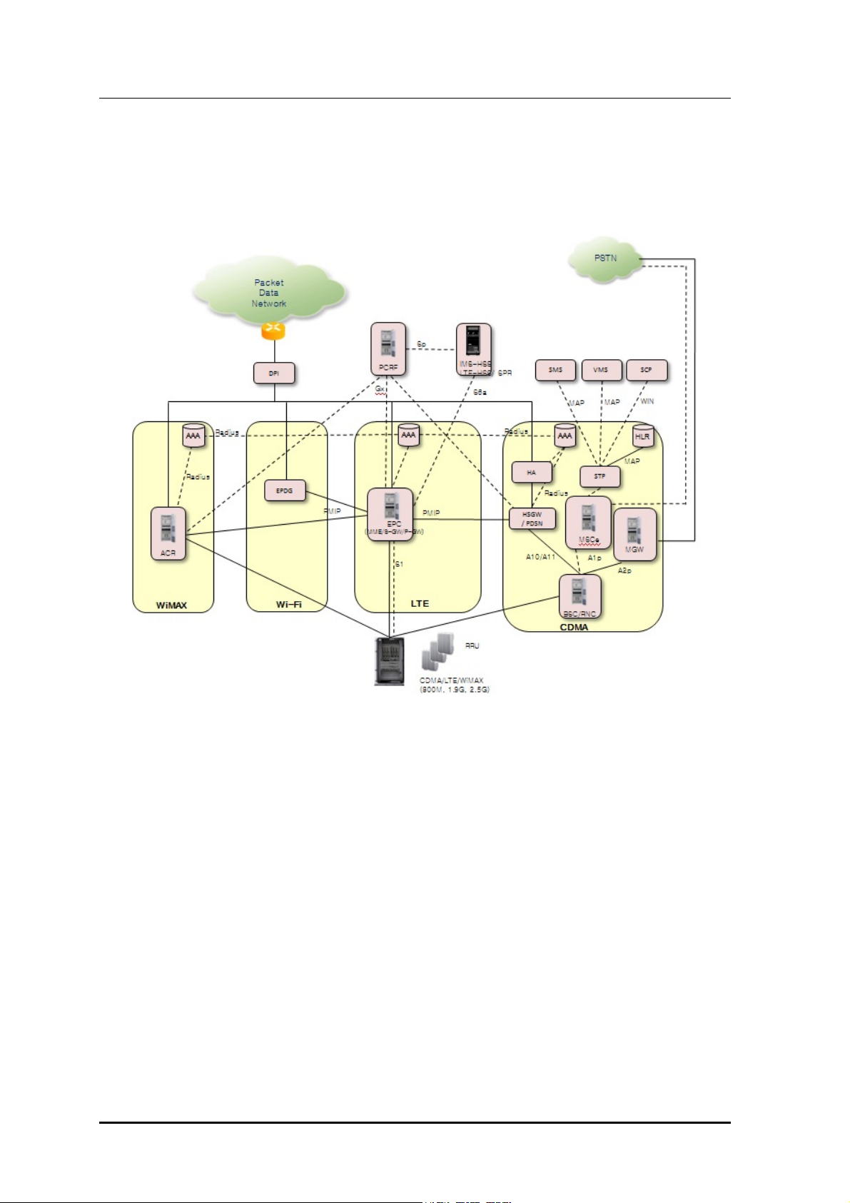
Samsung Multi-Modal System is configured as shown i n following Figure 1.2.
Figure 1.2 Samsung Multi-modal Network Architecture
As shown in Figure 1.2, Smart MBS system plays a role as CDMA/LTE basestation in a Samsung MultiModal System network where CDMA and LTE systems co-exist.
When operating as CDMA, Smart MBS communicates with BSC(CDMA controller), and operator may
use BSM(EMS of CDMA) to control and manage CDMA portion of Smart MBS..When operating as
LTE, it com muni cat es with EP C, a nd o per ato r m ay use LSM -R (EMS or LTE) to control and ma nage LTE
portion of Smart MBS.
Following network structure describes the type of each technology supported by Smart MBS.
1-4
© SAMSUNG Electronics Co., Ltd.
Smart MBS System Description
y
y
1.2.1 CDMA System Network Architecture
CDMA system network of “Samsung Multi-Modal System” consists of AN(Access Networks) for
terminal access, VCN(Voice Core Network) for voice ser vice, and PC N( Pac ket Core Net wor k) f or pac ket
data service.
AN consists of BTS, BSC(BTS controller), IP Network, Transport Network, and finally BSM to manage
these components. AN communicates with VCN(MGW, MSC/MSCe) and PCN(AN-AAA, PDSN) to
provide voice/data communication service to mobile subscribers.
MSCe
ESM
BSM
MGW
Proprietary
Proprietary
UE
A2p
Proprietar
Smart MBS
IS2000,
IS856
UE
BSC
A1p
A12
,A10,A11
Proprietar
Smart MBS
AN-AAA
Internet
PDSN
Figure 1.3 CDMA Network Architecture of Samsung Multi-Modal System
CDMA Net work Architecture of Samsung Multi-Modal System(where Smart MBS i s operated as C DMA
BTS) is shown in Figure 1.3. Following describes the feature per each CDMA network devices.
BTS (Base Transceiver Station)
BTS(CDMA Basestation) is a system that handles wireless interface with mobile terminals in accordance
with CDMA2000 1X and 1xEV-DO standards. It receives data from mobile terminal and forwards it to
Core network through BSC, and receives data from Core via BSC and forwards it to mobile terminal. In
order to play a role as wireless transceiver, BS manages RF resourc es such as CA(Carrier Allocation),
W alsh. Also, it supports RF(Radio Frequency) Scheduling and Power Control Functionality.
BSC (Base Station Controller)
© SAMSUNG Electronics Co., Ltd. 1-5

Samsung Multi-ModalSystem Abstract
Through various backhaul interfaces, BSC coordinates with multiple BTS, and provides r esources that
are required for communicating with BTS. BSC communicates with VCN to process “Voice/Circuit Data
Calls”, and coordinates with PCN to process “Packet Data Calls”. Also, it carries out
operation/maintenance function in conjunction with BSM. It executes RLP(Radio Link Protocol) and
SDU(Selection and Distribution Unit) function that Hand-Off will be available for mobile terminals.
BSC also has PCF/(SC/MM) feature that “session control and mobility management function” is
executed in 1xEV -DO network.
BSM (BSS System Manager)
BSM provides “operator interface” that operators can control and manage BCS and BTS. For
Operation/Maintenance of BSC and BTS, BSM provides required commands such as
“alarm/status/performance display”, “Configuration Management”, and “Parameter Control” of the
system.
PDSN (Packet Data Serving Node) System
PDSN is a system which connects PCN to CDMA2000 1X (or 1xEV-DO), and it
enables/maintains/disables the PPP to mobile terminal. PDSN particularly carries out functionality as
F A(Foreign Agent) for HA(Home Agent) to provide mobile IP service.
AN-AAA (Access Network-Authorization, Authentication and Accounting)
AN-AAA is a server that performs authentication for subscribers in CDMA2000 1xEV-DO network. ANAAA executes authentication based on NAI(Network Access Identifier), and manages the “mapping
data” of IMSI and terminal NAI.
MSC (Mobile service Switching Center)/MSCe (MSC emulator)
MSC(e) is a system component which provides “switching” role in CDMA2000 network. It provides
additional services by connecting subscribers to additional equipments or other network(PSTN)
MGW (Media Gateway)
MGW is an equipment that provides “bearer gateway functionality” (Media conversion and handling) in
a CDMA 2000 network. MGW exchanges PCM data(which is based on TDM) with PSTN, and
exchanges voice frame(which is based on IP) with BSC.
1.2.2 LTE System Network Structure
LTE network of Samsung Multi-Modal System incorporates Basestation(eNB), packet core(EPC), and
LSM/(MSS). The system consists of multiple basestations(eNB: Evolved UTRAN Node-B) and Gateway
(EPC: Evolved Packet Core, MME, S-GW/P-GW), and provides functionality for UE to connect to
external network.
In addition, LTE system provides LTE System Manager(LSM) and Self-Optimization Server Feature for
Operation/Maintenance of Basestation(eNB).
1-6
© SAMSUNG Electronics Co., Ltd.
Smart MBS System Description
PDN
Gy
EPC
Gz
OCS
Gx
S10
PCRF
Sp
S6a
EMS
LSM-C
CG
TL1
Gz
P-GW
S5/S8
S11
MMES-GW
HSS/SPR
S1
EMS
S1-U
S1MME
LSM-R
SNM P/FTP/UDP
RMI
Smart MBS
MSS
UE
X2-C
X2-U
Smart MBS
Uu
UE
Figure 1.4 Samsung Multi-Mode System’s LTE Network Architecture
LTE network architecture of Samsung Multi-Modal System, where the Smart MBS is operated as LTE’s
Basestation(eNB), is as shown in the Figure 1.4, and following features are available for each LTE
network equipment.
eNB (Evolved UTRAN Node-B)
LTE Basestation(eNB) is a system located between UE and EPC, and it handles the packet calls by
connecting to UE wirelessly in accordance w ith “LTE Air standard ”. eNB executes various functions
including Tx/Rx of Wireless signal, Modulation/Demodulation of packet traffic, packet scheduling for
efficient use of RF resources, HARQ (Hybrid Automatic Repeat Request) and ARQ (Automatic Repeat
Request) process, PDCP(Packet Data Convergence Protocol) of compressed packet head er, and wireless
resource control. Also, it synchronizes with EPC to execute Handover.
EPC (Evolved Packet Core)
EPC is a system between Basestation(eNB) and PDN. It incorporates MME(Mobility Management
Entity), S-GW (Serving Gateway), and PDN Gateway(P-GW).
MME handles control message via basestation(eNB) and NAS signaling protocol, and management of
mobility for terminal, management of T racking Area List, bearer and session management.
S-GW plays role as “anchor” on subscriber plane b etween 2G, 3G Acce ss system, and LTE system. It
manages/modifies packet transmit layer of downlink/uplink data.
P-GW allocates IP Address to UE, plays role as “anchor” for mobility between “LTE System” and “non3GPP Access Systems”, manages billing charges for different service levels, and handles
© SAMSUNG Electronics Co., Ltd. 1-7

Samsung Multi-ModalSystem Abstract
management/modification of the throughput rate.
LSM (LTE System Manager)
LSM provides a synchronized interface for operator that Operation/Maintenance can be performed for
Basestaion(eNB) by operator. It also provides Software management, configuration management,
performance mana gem ent, an d ala rm m ana gem ent featu res .
HSS(Home Subscriber Server)
HSS is a database management system that stores the parameter and geographical data of entire
subscribers. HSS manages important data including access availability, basic service, and additional
service of the subscriber. It also performs “Rooting Feature” for subscribers receiving calls.
MSS(Master SON Server)
MSS is a higher node of Local SON server. It synchronizes with Local SON Server to optimize the
synchronization in regards to Multi-LSM. MSS is a funct ion that is compatible with the operator OSS,
and the availability of this function will be decided after discussion with operator.
PCRF(Policy Charging & Rule Function)
PCRF may generate policy rule in order to apply “QoS/Billing Policies per each Service Flow”
dynamically . Or it m ay generate Policy rule t hat is appli ed uniform ly to multiple Service Flow.
Since IP edge contains PCEF(Policy and Charging Enforcement Function), Policy Rules(received from
PCRF) can be applied per each Service Flow.
OCS (Online Charging System)
If subscribers (with Online Billing information) makes call, subscriber’s billing information is
sent/received.
CG (Charging Gateway)
Stores the generated billing data, and provides billing data per each subscriber.
1-8
© SAMSUNG Electronics Co., Ltd.
Smart MBS System Description
1.3 Samsung Multi-Modal System Feature
Following is the feature supported by each mobile technology of Samsung Multi-Modal System .
1.3.1 CDMA System Feature
Following Figure shows CDMA system(BSC, BTS)based on 1X/1xEV-DO.
BSC
1XVoice
BTS
Voice Handler
SUA Handler
L3
1xEV-DO
Paging Controller
IP Packet Forwarding
Packet Classification
ARQ
Abis
HARQ
MAC
PHY
AN-AAA Client
SC/MM
A11 Handler
A10 Handler
RLP Handler
IP Packet Forwarding
Packet Classification
Figure 1.5 CDMA System Functional Structure
BSC works with voice core equipments (M SCe, M GW) t o manage signaling and bearer process for voice
service. In BSC, SUA Handler is responsible for Alp signaling with MSCe, and Voice Handler send s the
voice bearer traffic to MGW. In addition, it works with PDSN for 1X data and 1xEV-DO data service.
A10 Handler manages the bearer traffic of such d ata 1X Data and 1xEV-DO Data service. A11 Handler
manages signaling for data service. RLP Handler manages ARQ feature for data communication.
For Authentication of 1xEV-DO terminal, AN-AAA client is responsible for synchronization with ANAAA. SC/MM executes session control and mobility management for 1xEV-DO.
BTS is responsible for Radio Resource Control and terminal communication. Through CAI(Common Air
Interface), it provides features such as high speed data service, multimedia service, new hand off, in
accordance with standards defined in 3GPP2 C.S0024-0_v4.0, 3GPP2 C.S0024-A_v3.0, and 3GPP2
C.S0024-B_v3.0, 3GPP2 C.S0063-B_v1.0
© SAMSUNG Electronics Co., Ltd. 1-9
Samsung Multi-ModalSystem Abstract
1.3.2
LTE System Feature
Following Figure shows functional separation between eNB, MME, S-GW, P-GW of E-UTRAN in
accordance with 3GPP standard. Generally, eNB manages “Connected mode” at AS(Access Stratum)
level. MME manages Idle mod e terminals in NAS(Non-Access Stratum) lev el. Both S-GW and P-GW
performs “user data management” and provide the “link to foreign network”.
Following displays the functionality of eNB, MME, S-GW , and P-GW.
EPC
MME
S-GW
P-GW
NAS Security
Idle State Mobility
Handling
EPS Bearer Control
eNB(E-UTRAN)
RRC
PDCP
RLC
MAC
PHY
Mobility Anchoring
S1
Inter Cell RRM
RB Control
Connection Mobility Control
Radio Admission Control
eNB Measurement Configuration & Provision
Dynamic Resource Allocation (Scheduler)
UE IP address
allocation
Packet Filtering
Figure 1.6 Function of E-UTRAN and EPC
eNB
eNB manages E-UTRAN(Evolved UTRAN), the wireless acces s network of LTE system. Multiple eNB are
connected via X2 interface, and these eNB are connected to EPC(Evolved Packet Core ) via S1 interface.
Wireless protocol layer of eNB can be divided into Layer1, Layer2, and Layer 3. Layer 3 contains RRC
layer, Layer 2 contains three layers(MAC layer(sublayer), RLC layer, PDCP layer) where each layer
executes an independent process. RRC layer belongs to layer 3 of the wireless protocol. Generally, RRC
Layer is responsible for maintenance and control of RB(Radio Bearer), RRC connectivity, and Exchange of
System Data. Meanwhile, PDCP layer is responsible for header compression of IP packet, security features
like “ciphering/integrity check”, and “selective transmission feature” which can increase the efficiency of
“radio resource”
RLC Layer is responsible a) for segmentation and reassembly at MAC Layer for data which was received
from PDCP layer; b) of restoring the tx failure(at lower level) via retransmission (ARQ); and c) of
reordering which can be caused because by (HARQ in MAC layer)
For each bearer, MAC Layer distributes RF resources according to priority, multiplexes the data received
1-10
© SAMSUNG Electronics Co., Ltd.

Smart MBS System Description
from various “Upper Logi cal Channels” , and per forms HARQ (Hybrid ARQ).
MME(Mobility Management Entity)
MME works in conjunction with E-UTRAN(eNB) to handle “S1-AP signaling message”(of SCTP base;
used to control connection between MME and eNB) AND “NAS Signaling message” (of SCTP base; used
to control mobility and connection between terminal and EPC.) In add ition, it works in conjunction with
HSS to obtain subscriber information, modification, and authentication. It can work in conjunction with SGW, as utilizing GTP-C protocol, to allocate bearer path (for data routing and forwarding, release, and
modification)
It can also work in conjunction with SGSN(of 2G, 3G) and MSC to provide Mobility, HO, CS fallback, and
SMS service.
MME can handle mobility, idle mode UE reachability, TA list management, P-GW/S-GW selection,
authentication, and bearer managem ent.
MME supports mobility for handover between eNB, and supports handover between MME. Also, SGSN
selection is supported whe n it hand s over to 2 G, 3G, or 3 GPP netwo rk.
S-GW(Serving Gateway)
S-GW plays role as mobility anchor when handover is executed between eNB, and 3GPP. As a supported
function, packet data is “Routed”, “F orwarded”. Billing Policy can be configured differently per each of
UE, PDN, and QCN. It can m anage and modi fy the “packet transport layer” of the uplink/datalink data.
In addition, S-GW supports GTP and PMIP protocol in conjunction with MME, P-GW, and SGSN.
P-GW(PDN Gateway)
P-GW can execute Billing/Bearer policy in conjunction with PCRF, and per its policy. Billing, QoS, can be
managed/modified per service level. P-GW provides Packet filtering feature per each subscriber, and
allocates IP address to each UE. P-GW can manage/m odify packet transport layer of the downlink Data.
© SAMSUNG Electronics Co., Ltd. 1-11

Samsung Multi-ModalSystem Abstract
This page is intentionally left blank.
1-12
© SAMSUNG Electronics Co., Ltd.

Smart MBS System Description
Chapter 2. Smart MBS Abstract
2.1 Smart MBS System Description
Smart MBS is the Basestation of Samsung Multi-Modal System. It is managed by packet core (either BSC,
ACR, or EPC), and makes call to terminal to create CDMA/LTE links.
Smart MBS interfaces with UE via either CDMA(3GPP2 CDMA2000 1X Advanced and 1xEV-DO
Rev.0/Rev.A (20110408)), LTE(3GPP LTE Rel.8/9). It provides broadband high speed data service and
multimedia services.
In order to implement this, Smart MBS can perform Modulation/Demodulation (for voice or packet
traffic), assign Scheduling and Wireless Bandwidth (for efficient use of RF resources and to guarantee
QoS), handle ARQ(Automatic Repeat request), perform ranging feature, provide connection control
feature (for sending Smart MBS information and enable/maintain/disable the call), Synchronize
BSC/ACR/EPC, provides Power Control, and executes system operation management.
By Fast Ethernet/Gigabit Ethernet backhaul, Smart MBS synchronize the control station to transceive
reliable control signal and traffic signal.
Smart MBS is separated into UADU(Universal Platform Digital Unit, an indoor DU) and the
RRH(Remote Radio Head, a combined RF unit). UADU is mounted in the outdoor DU cabin et(along
with the rectifier) to support outdoor environment.
UADU is a digital component for 19” shelf. It can be mounted onto either indoor or outdoor 19 inch
commercial rack, and one UADU can provide the following maximum capacity. Based on operator’s
setup, it can be operated as omni type or sector type.
- CDMA 1X / EVDO : Max 8Carrier/3Sector(2Br)
Max 6Carrier/3Sect or(4Br)
- LTE (FDD) : Max 5Carrier/3Sector
- LTE (TDD) : Max 3Carrier/3Sector
RRH is RF component that is built into a single module. It can be mounted onto Walls, Poles, or Stands
in outdoor environments.
Depending on Frequency bandwidth and duplexing type, RRH can be classified into following types.
© SAMSUNG Electronics Co., Ltd. 2-1

Smart MBS Abstract
- RRH-C2: 800M Hz Cel lula r ban d, 2T x/2R x RF p ath
- RRH-P4 : 1.9GHz PCS band, 4Tx/4R x RF path
Smart MBS has other features provided as below.
Common Platform DU/RRH
Digital boards of each wireless technology, to be mounted in Smart MBS, share the common DU
platform. Therefore, different boards(for multiple technology) may be mounted in a single DU, and
operator can mount up to 4 DU in outdoor DU cabinet to implement various configuration.
RRH of Smart MBS can simultaneously support multiple technologies in the same duplexing type with
the same bandwidth.
RRH(Remote Radio Head) separated from DU(Digital Unit)
In order to provide ease of installation and various network structure, Smart MBS has separated RRH
from DU. Between RRH and DU, a fiber optic ‘Baseband I/Q and C&M’ interface, based on
CPRI(Common Public Radio Interface), is used to send/receive “data traffic signal” and “OAM data”. DU
and RRH gets -48VDC from rectifier inside the outdoor DU cabinet.
Provide Easy Installation
RRH integrates optic-sync component and RF signal processor, and is a small & light weight single
module. RRH can be mounted onto Walls, Poles, or Stands. In addition, distance between RRH and
Antenna is minimized that RF signal loss(caused by Feeder Line) is decreased. Therefore, it can provide
improved RF performance when compared to Basestation that has Digital Unit and RF Unit altogether.
Natural Cooling Mechanism
RRH(Remote Radio Head) may be installed in outdoor environment, and its thermal-dynamic design
efficiently dissipates heat without requirement of additional cooling mechanism. Also, no maintenance cost
is required for RRH cooling.
Feature for Loop-Back Test of the line between DU and RRH
In order to check functionality of the “Base-band I/Q and OAM interface” between DU and RRH, Smart
MBS provides Loop-back T est.
Provides Remote Firmware Downloading
RRH may be replaced with firmware to enhance service and upgrade new features. At this time, Site visit
is not required as firmware can be downloaded from basestation operation server (such as
BSM/WSM/LSM-R). Therefore, operator can minimiz e the site visit, reduce the maintenance co st, and
easily operate the system.
Provides Monitoring Port.
Through debug port of RRH, operator can monitor the information about the unit.
2-2
© SAMSUNG Electronics Co., Ltd.

Smart MBS System Description
Support for Smooth Migration
Smart MBS can provide migration from CDMA to 4G LTE )wireless telecommunication by eit her adding
“traffic processor card and channel card” or “software upgrade”.
In case of RRH, in the same frequency band, simple Software upgrade would allow conversion into 4G
wireless telecommunication. Also, simultaneous operation of 3G and 4G is possible.
Furthermore, following are the Smart MBS features per each wireless technology.
2.1.1 Smart MBS CDMA System Feature
Support for 1X Advanced
In order to improve voice capacity and data rate, Smart MBS supports “1X Advanced”.
In case of “1X Advanced”, EVRC-B, RLIC, QOF, New RC, QLIC, and MRD are implemented for voice
capacity enhancement.
QChat
Smart MBS supports QChat(Qualcomm Chat) which is a PTT service that is based on 1xEV-DO.
For QChat service, BSC/BTS runs in conjunction with QAS(QChat Application Server) and PDSN
to exchange “signaling and bearer traffic” with terminal. QChat can support 1:1 call and group call,
and reserve QoS(Quality of Service).
Provides Dual Band
Dual band is a feature that allows single basestation to provide different services in 2 different RF
bandwidths. Smart MBS can simultaneously provide service on 800MHz band and 1.9GHz band. With
exception of RRH, Smart MBS can utilize entire hardware to be shared for 2 bands. Smart MBS’s Digital
Unit can provide up to maximum capacity of 12 Carrier/3 Sector(2Br) or 6Carrier/3Sector(4Br). For
1.9GHz, Smart MBS supports 4Br.
Tx/RX Diversity Support
In order to improve RRH-C2 and RRH-P4, Smart MBS optionally provides TDTD(Time Delay Transmit
Diversity) feature that will transmit “CDMA Modem output of 1Tx” from “RF path of 2Tx”.
Also, in order to improve receive performance, RRH-C2 and RRH-P4 provides 2 Branch receive
diversity (which provides 2 receive path per each sector) as a standard. Optionally, Operator may choose
that RRH-P4 can provide 4 Branch receive Diversity which will provide 4 receive paths.
2.1.3 Smart MBS LTE System Feature
OFDMA/SC-FDMA Technology
Smart MBS can handle downlink OFDMA/uplink SC-FDMA channel processing that supports the
Physical Layer of LTE standard.
Downlink OFDMA can use sub-carrier, which are assigned to each subscriber, to simultaneously send
data to multiple users. Also, in accordan ce with the requested data transfer rate, it can assign single(or
© SAMSUNG Electronics Co., Ltd. 2-3
 Loading...