

Samsung SMH9187B/XAA, SMH9187W/XAA, SMH7185, SMH9187ST/XAA, SMH9187ST Service Manual
BASIC: SMH9187W
MODEL: SMH9187B
MODEL CODE: SMH9187B/XAA
1. Precaution
2. ProductSpecication
3. Disassembly and Reassembly
4. Troubleshooting
5. Exploded Views and Part List
6. PCB Diagrams
7. Wiring Diagrams
8. Schematic Diagrams
Refer to the service manual in the GSPN(see rear cover) for the more information.

• Contents
1. Precaution . . . . . . . . . . . . . . . . . . . . . . . . . . . . . . . . . . . . . . . . . . . . . . . . . . . . . . . . . . . . . . . . . . . . . . . . . . . . . .3
1-1 Safety precautions . . . . . . . . . . . . . . . . . . . . . . . . . . . . . . . . . . . . . . . . . . . . . . . . . . . . . . . . . . . . . . . . . . . . .4
1-2 Special High Voltage Precautions . . . . . . . . . . . . . . . . . . . . . . . . . . . . . . . . . . . . . . . . . . . . . . . . . . . . . . . . .5
2.Specications . . . . . . . . . . . . . . . . . . . . . . . . . . . . . . . . . . . . . . . . . . . . . . . . . . . . . . . . . . . . . . . . . . . . . . . . . . .6
2-1 Features . . . . . . . . . . . . . . . . . . . . . . . . . . . . . . . . . . . . . . . . . . . . . . . . . . . . . . . . . . . . . . . . . . . . . . . . . . . . .6
2-2 Accessory . . . . . . . . . . . . . . . . . . . . . . . . . . . . . . . . . . . . . . . . . . . . . . . . . . . . . . . . . . . . . . . . . . . . . . . . . . . .7
2-3 Table of Specications . . . . . . . . . . . . . . . . . . . . . . . . . . . . . . . . . . . . . . . . . . . . . . . . . . . . . . . . . . . . . . . . . .8
3. Disassembly and Reassembly . . . . . . . . . . . . . . . . . . . . . . . . . . . . . . . . . . . . . . . . . . . . . . . . . . . . . . . . . . . . . .9
3-1 Disassembly of Assembly Grille and Panel Outer . . . . . . . . . . . . . . . . . . . . . . . . . . . . . . . . . . . . . . . . . . . . .9
3-2 Replacement of High Voltage Transformer and HVC and Base bottom . . . . . . . . . . . . . . . . . . . . . . . . . . . 11
3-3 Replacement of Magnetron . . . . . . . . . . . . . . . . . . . . . . . . . . . . . . . . . . . . . . . . . . . . . . . . . . . . . . . . . . . . .13
3-4 Replacement of Door Assembly . . . . . . . . . . . . . . . . . . . . . . . . . . . . . . . . . . . . . . . . . . . . . . . . . . . . . . . . . .14
3-5 Replacement of Fuse . . . . . . . . . . . . . . . . . . . . . . . . . . . . . . . . . . . . . . . . . . . . . . . . . . . . . . . . . . . . . . . . . .16
3-6 Replacement of Drive Motor . . . . . . . . . . . . . . . . . . . . . . . . . . . . . . . . . . . . . . . . . . . . . . . . . . . . . . . . . . . .16
3-7 Replacement of stirrer motor . . . . . . . . . . . . . . . . . . . . . . . . . . . . . . . . . . . . . . . . . . . . . . . . . . . . . . . . . . . .17
3-8 Removal of stirrer . . . . . . . . . . . . . . . . . . . . . . . . . . . . . . . . . . . . . . . . . . . . . . . . . . . . . . . . . . . . . . . . . . . . .18
3-9 Replacement of Control Circuit Board . . . . . . . . . . . . . . . . . . . . . . . . . . . . . . . . . . . . . . . . . . . . . . . . . . . . .19
3-10 Replacement of Cooktop lamp . . . . . . . . . . . . . . . . . . . . . . . . . . . . . . . . . . . . . . . . . . . . . . . . . . . . . . . . . .20
3-11 Replacement of Oven Light . . . . . . . . . . . . . . . . . . . . . . . . . . . . . . . . . . . . . . . . . . . . . . . . . . . . . . . . . . . .21
4. Troubleshooting . . . . . . . . . . . . . . . . . . . . . . . . . . . . . . . . . . . . . . . . . . . . . . . . . . . . . . . . . . . . . . . . . . . . . . . .22
4-1 Error Code Numbering Rule . . . . . . . . . . . . . . . . . . . . . . . . . . . . . . . . . . . . . . . . . . . . . . . . . . . . . . . . . . . . .22
4-2 Error Code List . . . . . . . . . . . . . . . . . . . . . . . . . . . . . . . . . . . . . . . . . . . . . . . . . . . . . . . . . . . . . . . . . . . . . . .22
4-3 Electrical Malfunction . . . . . . . . . . . . . . . . . . . . . . . . . . . . . . . . . . . . . . . . . . . . . . . . . . . . . . . . . . . . . . . . . .24
5. Exploded Views and Parts List . . . . . . . . . . . . . . . . . . . . . . . . . . . . . . . . . . . . . . . . . . . . . . . . . . . . . . . . . . . .27
5-1 Exploded Views . . . . . . . . . . . . . . . . . . . . . . . . . . . . . . . . . . . . . . . . . . . . . . . . . . . . . . . . . . . . . . . . . . . . . .27
5-2 Main Parts List . . . . . . . . . . . . . . . . . . . . . . . . . . . . . . . . . . . . . . . . . . . . . . . . . . . . . . . . . . . . . . . . . . . . . . .28
5-3 Door Parts List . . . . . . . . . . . . . . . . . . . . . . . . . . . . . . . . . . . . . . . . . . . . . . . . . . . . . . . . . . . . . . . . . . . . . . .30
5-4 Control Parts List . . . . . . . . . . . . . . . . . . . . . . . . . . . . . . . . . . . . . . . . . . . . . . . . . . . . . . . . . . . . . . . . . . . . .31
5-5 Standard Parts List . . . . . . . . . . . . . . . . . . . . . . . . . . . . . . . . . . . . . . . . . . . . . . . . . . . . . . . . . . . . . . . . . . . .32
6. PCB Diagrams . . . . . . . . . . . . . . . . . . . . . . . . . . . . . . . . . . . . . . . . . . . . . . . . . . . . . . . . . . . . . . . . . . . . . . . . . .33
6-1 PCB Diagrams . . . . . . . . . . . . . . . . . . . . . . . . . . . . . . . . . . . . . . . . . . . . . . . . . . . . . . . . . . . . . . . . . . . . . . .33
6-2 PCB Diagrams . . . . . . . . . . . . . . . . . . . . . . . . . . . . . . . . . . . . . . . . . . . . . . . . . . . . . . . . . . . . . . . . . . . . . . .34
7. Wiring Diagrams . . . . . . . . . . . . . . . . . . . . . . . . . . . . . . . . . . . . . . . . . . . . . . . . . . . . . . . . . . . . . . . . . . . . . . . .35
7-1 Wiring Diagrams . . . . . . . . . . . . . . . . . . . . . . . . . . . . . . . . . . . . . . . . . . . . . . . . . . . . . . . . . . . . . . . . . . . . . .35
8. Schematic Diagrams . . . . . . . . . . . . . . . . . . . . . . . . . . . . . . . . . . . . . . . . . . . . . . . . . . . . . . . . . . . . . . . . . . . . .37
8-1 Schematic Diagrams . . . . . . . . . . . . . . . . . . . . . . . . . . . . . . . . . . . . . . . . . . . . . . . . . . . . . . . . . . . . . . . . . .37
2
1. Precaution
3
1. Precaution
Follow these special safety precautions. Although the microwave oven is completely safe during ordinary use,
repair work can be extremely hazardous due to possible exposure to microwave radiation, as well as potentially
lethal high voltages and currents.
1-1 Safety precautions ( )
1. All repairs should be done in accordance with the
procedures described in this manual. This product
complies with Federal Performance Standard 21
CFR
2.
Microwave emission check should be performed to
prior to servicing if the oven is operative.
3.
If the oven operates with the door open :Instruct
the user not to operate the oven and contact
the manufacturer and the center for devices and
radiological health immediately.
4.
Notify the Central Service Center if the microwave
leakage exceeds 5 mW/cm2.
5. Check all grounds.
6. Do not power the MWO from a “2-prong” AC cord.
Be sure that all of the built-in protective devices are
replaced. Restore any missing protective shields.
7.
When reinstalling the chassis and its assemblies,
be sure to restore all protective devices, including:
nonmetallic control knobs and compartment covers.
8.
Make sure that there are no cabinet openings
through which people --particularly children--might
insert objects and contact dangerous voltages.
Examples: Lamp hole,ventilation slots.
9.
Inform the manufacturer of any oven foundto have
emission in excess of 5 mW/cm2 ,Make repairs to
bring the unit into compliance at no cost to owner
and try to determine cause. Instruct owner not to use
oven until it has been brought into compliance.
CENTRAL SERVICE CENTER
10.
Service technicians should remove their watches
while repairing an MWO.
11.
To avoid any possible radiation hazard,replace parts
in accordance with the wiring diagram. Also, use
only the exact replacements for the following parts:
Primary and secondary interlock switches, interlock
monitor switch.
12.
If the fuse is blown by the Interlock Monitor Switch:
Replace all of the following at the same time:
Primary, door sensing switch and power relay, as
well as the Interlock Monitor Switch. The correct
adjustment of these switches is described elsewhere
in this manual. Make sure that the fuse has the
correct rating for the particular model being repaired.
13.
Design Alteration Warning: Use exact replacement
parts only, i.e.,only those that are specied in
thedrawings and parts lists of this manual. This
is especially important for the Interlock switches,
described above. Never alter or add to the
mechanical or electrical design of the MWO.
Any design changes or additions will void the
manufacturer’s warranty. Always unplug the unit’s
AC power cord from the AC power source before
attempting to remove or reinstall any component or
assembly.
14. Never defeat any of the B+ voltage interlocks. Do not
apply AC power to the unit (or any of its assemblies)
unless all solid-state heat sinks are correctly
installed.
15.
Some semiconductor (“solid state”) devices
are easily damaged by static electricity. Such
components are called Electrostatically Sensitive
Devices (ESDs). Examples include integrated
circuits and eld-effect transistors. Immediately
before handling any semiconductor components or
assemblies, drain the electrostatic charge from your
body by touching a known earth ground.
16.
Always connect a test instrument’s ground lead to
the instrument chassis ground before connecting the
positive lead; always remove the instrument’s ground
lead last.
17.
When checking the continuity of the witches or
transformer, always make sure that the power is
OFF, and one of the lead wires is disconnected.
18.
Components that are critical for safety are indicated
in the circuit diagram by shading, or .
19.
Use replacement components that have the same
ratings, especially for ame resistance and dielectric
strength specications. A replacement part that does
not have the same safety characteristics as the
original might create shock, re or other hazards.
NOTE : Connect the oven to a 20A. When
connecting the oven to a 15A,make sure that circuit
breaker can operate.
4
1. Precaution
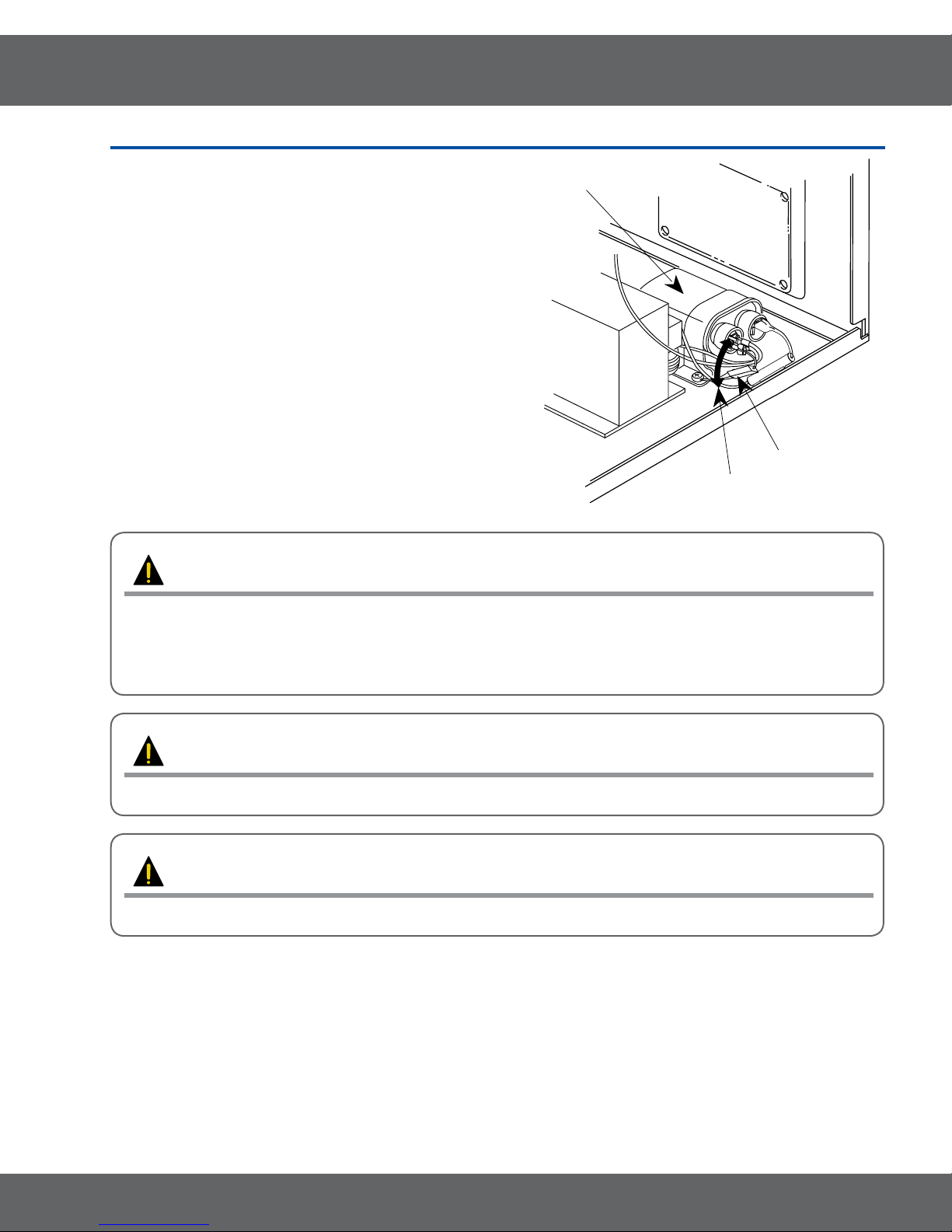
H. V. Diode
Short
H. V. Capacitor
1-2 Special High Voltage Precautions
1. High Voltage Warning Do not attempt to measure any of
the high voltages --this includes the lament voltage of the
magnetron. High voltage is present during any cook cycle.
Before touching any components or wiring, always unplug
the oven and discharge the high voltage capacitor (See
Figure 1-1)
2.
The high-voltage capacitor remains charged about 30
seconds after disconnection. Short the negative terminal
of the high-voltage capacitor to to the oven chassis. (Use a
screwdriver.)
3.
High voltage is maintained within specied limits by close-
tolerance, safety-related components and adjustments. If
the high voltage exceeds the specied limits, check each
of the special components.
PRECAUTION
There exists HIGH VOLTAGE ELECTRICITY with high current capabilities in the circuits of the HIGH
VOLTAGE TRANSFORMER secondary and lament terminals. It is extremely dangerous to work on or
near these circuits with the oven energized.
DO NOT measure the voltage in the high voltage circuit including lament voltage of magnetron.
PRECAUTION
Servicemen should remove their watches whenever working close to or replacing the magnetron.
PRECAUTION
Never touch any circuit wiring with your hand nor with uninsulated tool during operation.
5

2.Specications
2-1 Features
• Professional Design
• Turbo vent
Product Features
Samsung New OTR with Stainless Steel, it has professional look
and the design matches great with other kitchen appliances, so that
itprovidesharmoniouskitcheninteriorandnallycompletestotal
kitchen solution.
With 400CFM ventilation power, New OTR can keep the comfortable
cooking condition by absorbing smoke and odor from cook-top.
Moreover, it provides the silent condition that is equivalent noise
level to other OTR with lower ventilation power.
The Strongest power without additional noise!
That’sthebenetyoucanfeelfromNewOTR!
• Big Interior capacity for
convenience
• Sensor cook
• VFD display
With the 1.8 cu.ft capacity, it offers enough space to cook.
The big capacity combined with 1,100 watts of output achieves
superior cooking results.
Don’t worry about failure of your cooking!
New OTR’s sensor technology offers the best dish.
Only thing you need to do is just select the cooking menu, and then
youwillbesatisedwiththecookingresultsbysensorcook.
With more informative VFD display, the OTR helps you use all the
function it has with ease.
6
2.Specications
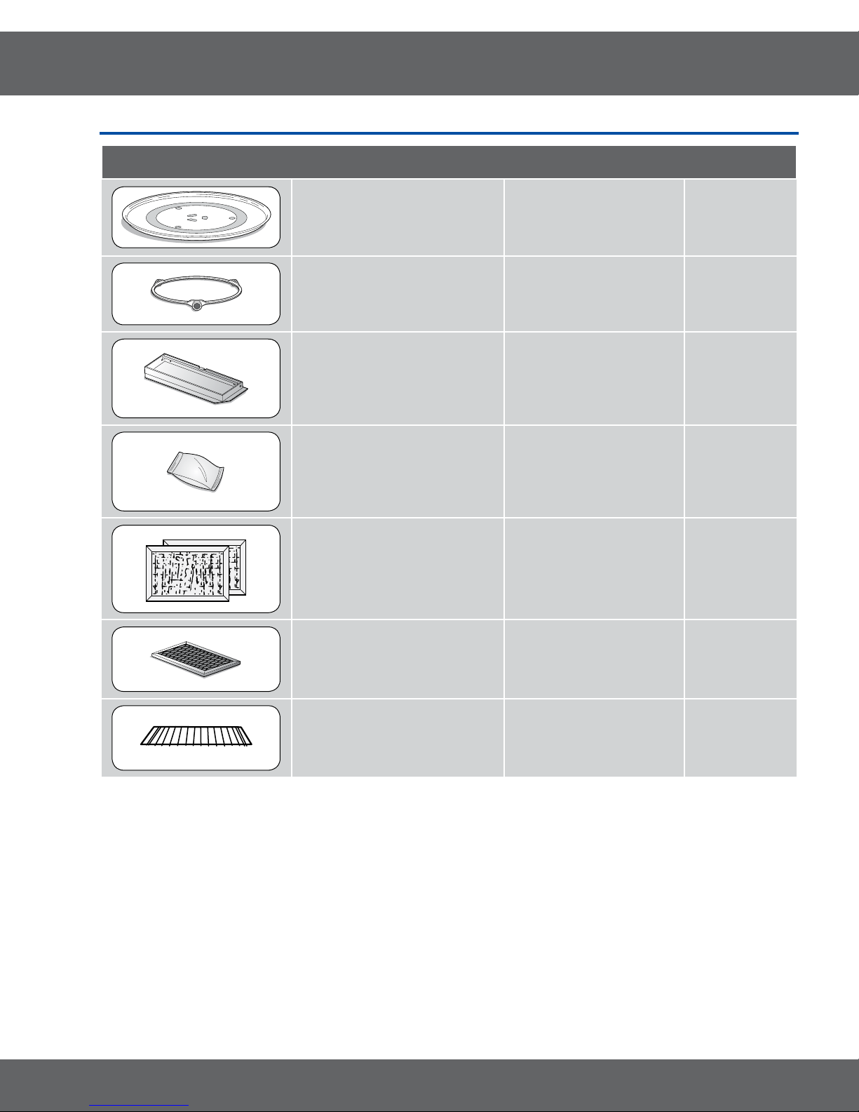
2-2 Accessory
Item Description Code No. Q’ty
TRAY COOKING DE74-20002A 1
ASSY-GUIDE ROLLER DE97-00368A 1
ASSY-HOOD DAMPER DE92-90242D 1
ASSY-HARD WARE DE92-90505E 1
FILTER AIR DE63-00196A 2
FILTER CHARCOAL DE63-00367D 1
RACK-WIRE DE75-00036B 1
7
2.Specications
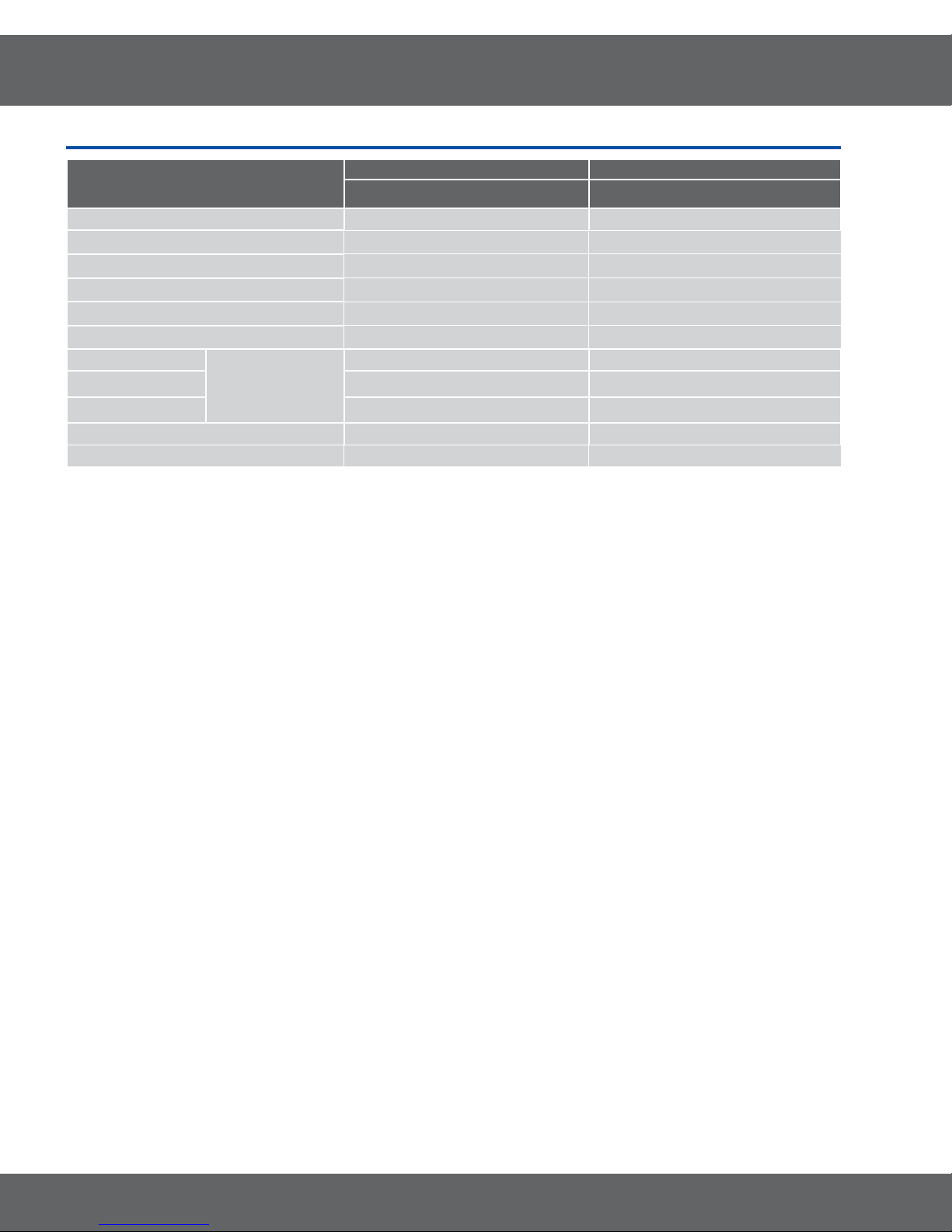
2-3TableofSpecications
Items
SMH9187W/XAA SMH9187B/XAA
Oven Cavity 1.8 1.8
Controls 10 power levels, including defrost 10 power levels, including defrost
Timer 99 minutes, 99seconds 99 minutes, 99seconds
Power Source 120VAC, 60Hz 120VAC, 60Hz
Power consumption 1650 Watts 1650 Watts
Power Output 1100 Watts 1100 Watts
Basic Model New Model
7/8
Oven Cavity
Outside 29
Shipping 33
Dimensions
(W x H x D inches)
20
7/8
3/8
x 9
x 16
x 19
31/32
1/2
15/16
x 14
x 15
x 19
9/16
15/32
13/32
33
20
29
7/8
3/8
7/8
x 19
x 9
x 16
31/32
1/2
15/16
x 14
x 15
x 19
9/16
15/32
13/32
Net/Gross Weight 51.6Kg / 62.7lbs 51.6Kg / 62.7lbs
Export Zone USA USA
8
3. Disassembly and Reassembly
MAGNETRON, MOTOR ASSEMBLY, VENT BLOWER AND HIGH VOLTAGE TRANSFORMER
Oven must be removed from wall.
REMOVING OVEN FROM WALL (2 PEOPLE REQUIRED)
Oven is hooked on metal tabs at bottom of wall mounting plate and to cabinet by (3) top cabinet bolts.
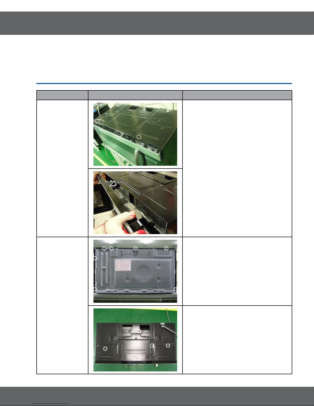
3-1 Disassembly of Assembly Grille and Panel Outer
Parts Explaination Photo Explaination
1. Disconnect oven power.
Grille
Panel Outer
2. Remove Grille.
1)
Remove 2 screws
2)
Slide the Grille to the left, then pull it
straght out.
1. Disconnect oven power.
2. Remove Grille.
3. Remove Screw.(7)
4. Remove Screw.(4)
9
3. Disassembly and Reassembly
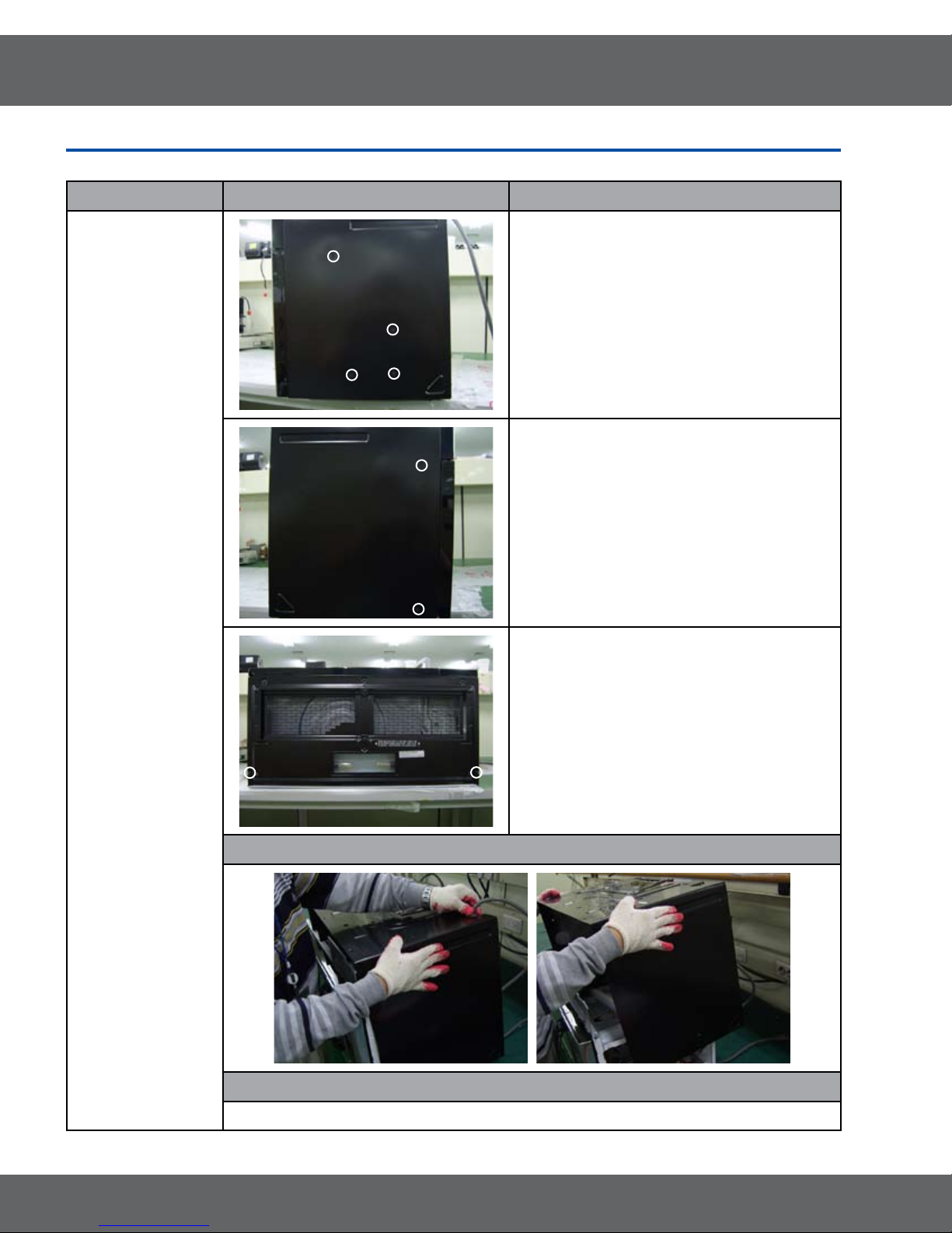
3-1 Disassembly of Assembly Grille and Panel Outer
Parts Explaination Photo Explaination
5. Remove Screw.(4)
6. Remove Screw.(2)
Panel Outer
7. Remove Screw.(2)
Explaination Photo
Explaination
8. Remove Panel Outer.
10
3. Disassembly and Reassembly
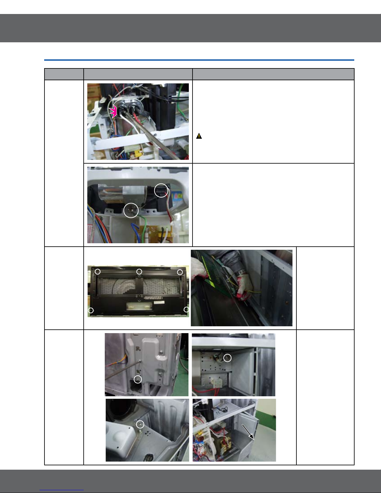
3-2 Replacement of High Voltage Transformer and HVC and Base bottom
Parts Explaination Photo Explaination
1. Disconnect Oven Power.
2. Remove Panel Outer.
3. Discharge The High Voltage Capacitor.
ATTENTION : When discharge must become ground
terminal of HVC and metal of around.
High
voltage
capacitor
4. Remove screw.(1)
5. Disconnect the Lead Wire.
Base
Bottom
HV Trans
1. Remove
Screw.(5)
2.
Disconnect
Lamp
Housing.
3.
Remove Base
bottom.
1. Disconnect
Oven Power.
2.
Remove the
Base bottom
and Panel
Outer.
3.
Disassembly
the Bracket
Duct upper
after remove
screw.
11

3. Disassembly and Reassembly
3-2 Replacement of High Voltage Transformer and HVC and Base bottom
Parts Explaination Photo Explaination
4. Disconnect the Lead Wire.
HV Trans
5. Remove screw.(3)
6. Take out the HV Trans.
12
 Loading...