

Samsung SMH7178STE, SMH7178STD, SMH7175WC, SMH7175BE, SMH7175WE Service Manual
MICROWAVE OVEN
BASIC : SMH7178STD
MODEL : SMH7178STE
Manual
SERVICE
MICROWAVE OVEN CONTENTS
1. Precaution
2. Specifications
3. Operating Instructions
4. Disassembly and Reassembly
5. Alignment and Adjustments
6. Troubleshooting
7. Exploded Views and Parts List
8. PCB Diagrams
SEA
9. Schematic Diagrams
10. Reference

Contents
1. Precaution 1
1-1 Safety precautions 1
1-2 Special Servicing Precautions (Continued) 2
1-3 Special High Voltage Precautions 2
2. Specifications 3
2-1 Table of Specifications 3
3. Operating Instructions 4
3-1 Control Panel 4
3-2 Features & External Views 5
3-3 Accessary 6
3-4 INSTALLATION 7
3-4 REUSABLE GREASE FILTERS 8
4. Disassembly and Reassembly 9
4-1 Replacement of Magnetron, Motor Assembly and Lamp 9
4-2 Replacement of High Voltage Transformer 9
4-3 Replacement of Door Assembly 10
4-3-1 Removal of Door “C” 10
4-3-2 Removal of Door “E” 10
4-3-3 Removal of Key Door & Spring 10
4-3-4 Reassembly Test 11
4-4 Replacement of Fuse & H.V.Trans Fuse 11
4-5 Replacement of Drive Motor 11
4-6 Replacement of stirrer motor 12
4-7 Removal of stirrer 12
4-8 Replacement of Control Circuit Board 13
4-8-1 Removal of Control Box 13
4-3-4 Removal of P.C.B Assembly 13
5. Alignment and Adjustments 14
5-1 High Voltage Transformer 14
5-2 Low Voltage Transformer 14
5-3 Magnetron 14
5-4 High Voltage Capacitor 15
5-5 High Voltage Diode 15
5-6 Main Relay and Power Control Relay 15
5-7 Adjustment of Primary Switch, Door Sensing Switch and Monitor Switch 15
5-8 VENT EXHAUST BLOWER MOTOR 16
5-9 THERMAL CUTOUT(TCO’s) 17
5-9-1 Oven Thermal Cutout (Flame sensor) 17
5-9-2 Replacement of Flame Sensor 17
5-9-3 Bottom Thermal Cutout 18
5-9-4 Magnetron Thermal Cutout 18
5-9-5 Magnetron Thermal Cutout 19
5-10 SENSOR 19
5-11 Output Power of Magnetron 20
5-12 Procedure for Measurement of Microwave Energy Leakage 21
5-13 Check for Microwave Leakage 21
5-14 Note on Measurement 21
5-15 Leakage Measuring Procedure 21
6. Troubleshooting 22
6-1 Electrical Malfunction 22
6-1 Electrical Malfunction(continued) 23
7. Exploded Views and Parts List 24
7-1 Exploded Views 24
7-2 Main Parts List 25
Contents
7-3 Control & Door Parts List 28
7-4 Standard Parts List 29
8. P.C.B Diagrams 30
8-1 P.C.B Diagrams 30
8-2 P.C.B Parts List 31
8-2 P.C.B Parts List(continued) 32
9. Schematic Diagrams 33
9-1 Schematic Diagrams 33
10. Reference 34
10-1 Model name standard 34
10-2 Customer inquiry cases and countermeasures 35
10-2 Customer inquiry cases and countermeasures (Continued) 36

PRECAUTIONS TO BE OBSERVED BEFORE AND
DURING SERVICING TO AVOID POSSIBLE
EXPOSURE TO EXCESSIVE MICROWAVE ENERGY
(a) Do not operate or allow the oven to be
operated with the door open.
(b) Make the following safety checks on all
ovens to be serviced before activating the
magnetron or other microwave source,
and make repairs as necessary:
(1) Interlock operation,
(2) proper door closing,
(3) seal and sealing surfaces
(arcing, wear, and other damage),
(4) damage to or loosening of hinges and
latches,
(5) evidence of dropping or abuse.
(c) Before turning on microwave power for
any service test or inspection within the
microwave generating compartments,
check the magnetron, wave guide or
transmission line, and cavity for proper
alignment, integrity, and connections.
(d) Any defective or misadjusted components
in the interlock, monitor, door seal, and
microwave generation and transmission
systems shall be repaired, replaced, or
adjusted by procedures described in this
manual before the oven is released to the
owner.
(e) A Microwave leakage check to verify
compliance with the Federal performance
standard should be performed on each
oven prior to release to the owner.
1. Precaution
Follow these special safety precautions. Although the microwave oven is completely safe during ordinary use,
repair work can be extremely hazardous due to possible exposure to microwave radiation, as well as potentially
lethal high voltages and currents.
1-1 Safety precautions ( )
1. All repairs should be done in accordance with the
procedures described in this manual. This product
complies with Federal Performance Standard 21
CFR Subchapter J(DHHS).
2. Microwave emission check should be performed
to prior to servicing if the oven is operative.
3. If the oven operates with the door open :
Instruct the user not to operate the oven and
contact the manufacturer and the center for devices
and
radiological health immediately.
4. Notify the Central Service Center if the
microwave leakage exceeds 5 mW/cm2.
5. Check all grounds.
6. Do not power the MWO from a “2-prong”
AC cord. Be sure that all of the built-in
protective devices are replaced. Restore any
missing protective shields.
7. When reinstalling the chassis and its
assemblies, be sure to restore all protective
devices, including: nonmetallic control
knobs and compartment covers.
8. Make sure that there are no cabinet openings
through which people --particularly children
--might insert objects and contact dangerous
voltages. Examples: Lamp hole,ventilation slots.
9. Inform the manufacturer of any oven foundto
have emission in excess of 5 mW/cm2 ,Make
repairs to bring the unit into compliance at no cost
to owner and try to determine cause.
Instruct owner not to use oven until it has been
brought into compliance.
11. To avoid any possible radiation hazard,replace
parts in accordance with the wiring diagram. Also,
use only the exact replacements for the following
parts: Primary and secondary interlock switches,
interlock monitor switch.
12. If the fuse is blown by the Interlock Monitor Switch:
Replace all of the following at the same time:
Primary, door sensing switch and power relay, as
well as the Interlock Monitor Switch. The correct
adjustment of these switches is described
elsewhere in this manual. Make sure that the fuse
has the correct rating for the particular model being
repaired.
13. Design Alteration Warning:
Use exact replacement parts only, i.e.,only those
that are specified in thedrawings and parts lists
of this manual. This is especially important for the
Interlock switches, described above. Never alter
or add to the mechanical or electrical design of the
MWO. Any design changes or additions will void
the manufacturer’s warranty. Always unplug the
unit’s AC power cord from the AC power source
before attempting to remove or reinstall any
component or assembly.
14. Never defeat any of the B+ voltage interlocks.
Do not apply AC power to the unit (or any of its
assemblies) unless all solid-state heat sinks are
correctly installed.
15. Some semiconductor (“solid state”) devices are
easily damaged by static electricity. Such
components are called Electrostatically Sensitive Devices (ESDs). Examples include integrated
circuits and field-effect transistors. Immediately
before handling any semiconductor components
or assemblies, drain the electrostatic charge from
your body by touching a known earth ground.
CENTRAL SERVICE CENTER
10. Service technicians should remove their watches
while repairing an MWO.
16. Always connect a test instrument’s ground lead to
the instrument chassis ground before connecting
the positive lead; always remove the instrument’s
ground lead last.
- 1 -
1-2 Special Servicing Precautions (Continued)
17. When checking the continuity of the witches or transformer,
always make sure that the power is OFF, and one of the
lead wires is disconnected.
18. Components that are critical for safety are indicated in the
circuit diagram by shading, or .
19. Use replacement components that have the same ratings,
especially for flame resistance and dielectric strength specifications.
A replacement part that does not have the same safety characteristics
as the original might create shock, fire or other hazards.
NOTE : Connect the oven to a 20A. When connecting the oven to a
15A,make sure that circuit breaker can operate.
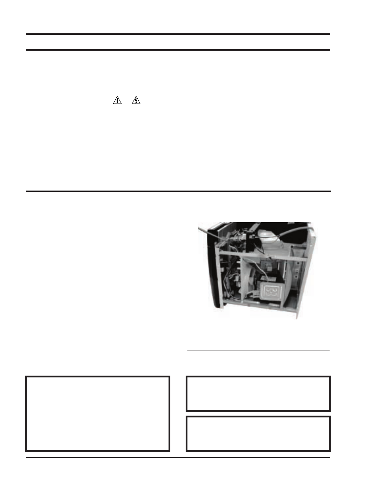
1-3 Special High Voltage Precautions
1. High Voltage Warning Do not attempt to
measure any of the high voltages --this includes
the filament voltage of the magnetron. High
voltage is present during any cook cycle.
Before touching any components or wiring,
always unplug the oven and discharge the high
voltage capacitor (See Figure 1-1)
2. The high-voltage capacitor remains charged
about 30 seconds after disconnection. Short the
negative terminal of the high-voltage capacitor to
to the oven chassis. (Use a screwdriver.)
3. High voltage is maintained within specified limits
by close-tolerance, safety-related components
and adjustments. If the high voltage exceeds the
specified limits, check each of the special
components.
High Voltage Capacitor
Fig. 1-1 Discharging High Voltage Capacitor
PRECAUTION
There exists HIGH VOLTAGE ELECTRICITY with
high current capabilities in the circuits of the HIGH
VOLTAGE TRANSFORMER secondary and filament terminals. It is extremely dangerous to work
on or near these circuits with the oven energized.
DO NOT measure the voltage in the high voltage
circuit including filament voltage of magnetron.
PRECAUTION
Never touch any circuit wiring with your hand nor
with uninsulated tool during operation.
PRECAUTION
Servicemen should remove their watches whenever working close to or replacing the magnetron.
- 2 -
2. Specifications
2-1 Table of Specifications
TIMER
POWER SOURCE
POWER CONSUMPTION
OUTPUT POWER
OPERATING FREQUENCY
MAGNETRON
COOLING METHOD
OUTSIDE DIMENSIONS
NET WEIGHT
SHIPPING WEIGHT
99 MINUTES 99 SECONDS
120V 60Hz, AC
MICROWAVE : 1,650W
FROM 100 TO 1100W(10 LEVEL POWER)
(IEC-705 TEST PROCEDURE)
2,450MHz
OM75P(10)ERHN
COOLING FAN MOTOR
29
14/16
”(W) x 15
15/16
”(H) x 15
11/32
”(D) mm
58.4 lbs
64.4 lbs
- 3 -
3. Operating Instructions
1
2
3
10
4
6
7
12
13
8
16
14
18
17
15
11
9
5
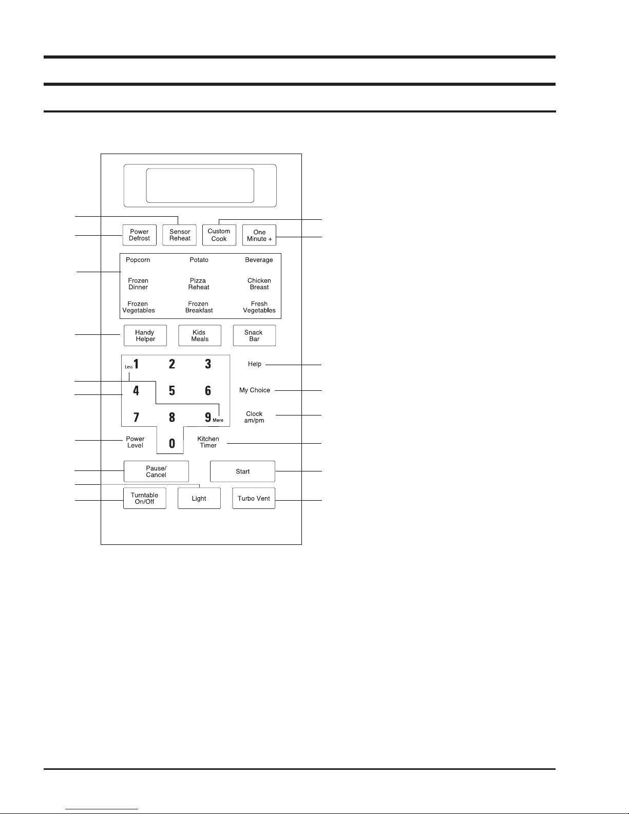
3-1 Control Panel
1. Sensor Reheat
2. Power Defrost
Sets weight of food to be defrosted.
3. Sensor Cook Buttons p.11
Sensor settings to cook popular foods.
4. Handy Helper, Kids Meals, Snack Bar
Selects type of dish to be reheated.
5. More/Less
Increase or decrease cooking time.
6. Number Buttons
Set cooking times or amounts and power
levels other than high.
7. Power Level
Press this pad to set a power level other
than high.
8. Clock am/pm
Sets current time
9. Light On/Night/Off Button
10. Turntable On/Off Button
11. One Minute +
Press once for every minute of cooking at
High power.
12. My Choice
Press to set non-cooking feature.
13. Custom Cook
Press twice to program your favorite recipe.
Press once to cook with that recipe.
14. Start
Press to start cooking.
15. Kitchen Timer
Sets kitchen or convenience timer.
16. Pause/Cancel
Press to pause oven or correct a mistake.
17. Help
Press to see help information about the
feature you are using.
18. Vent Fan Turbo/Hi/Low/Off Button
- 4 -
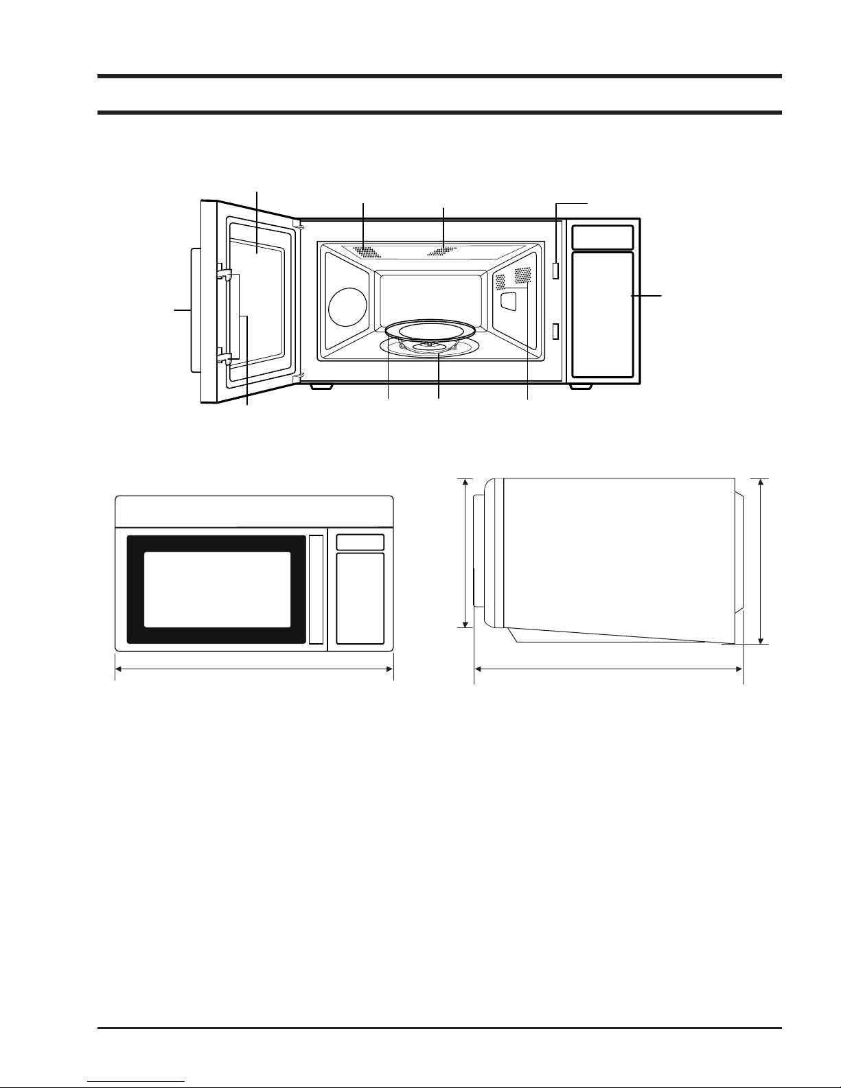
Door
Door Latches
Handle
Ventilation Holes
Oven Light
Safety Interlock Holes
Control Panel
Intake Holes
Glass Tray
Guide Roller
398mm758.9mm
417.25mm
405mm
3-2 Features & External Views
- 5 -
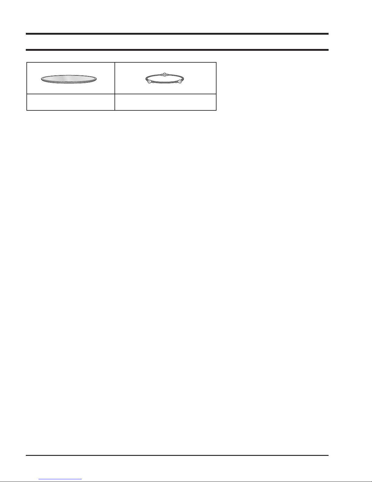
3-3 Accessary
Glass tray Roller guide ring
- 6 -
Mounting Plate
REMOVE SCREWS
3-4 INSTALLATION
The Microwave Oven is supported by a special
bracket assembly (mounting system) supplied with
the oven. The bracket assembly must be mounted to
the wall with toggle bolts through the wall, and a lag
screw into a wall stud. After the bracket assembly is
installed, the unit can be slid over the two rails of the
bracket assembly. Two bolts are run down through the
cabinet bottom and into the oven case to pull the oven
up against the cabinet bottom.
NOTE : For easier removal and personal safety it is
recommended that two people remove this
product.
CAUTION!
The mounting surface must be capable of supporting the cabinet load, in addition to the 64 pound
product, plus additional loads of up to 50 pounds or a
total weight of 114 pounds. This product cannot be
installed to cabinet arrangements such as an island or
peninsula. It must be mounted to both a top cabinet
and wall.
VENT BLOWER
The vent or exhaust blower is located at the top
of the oven. It is shipped for vertical exhaust but
can be changed to rear exhaust or recirculating
(See installation instrustions on how to change
and/or blower section on how to remove).
COOKTOP LIGHTS
One 40-watt screw base incandescent bulbs are
located on the bottom between the two grease
filters. The bulbs are user replaceable by removing
one screw and lowering access cover. The bulbs
could be difficult to remove when replaced for the
first time. a silicone glue is used to secure them
during shipping.
OVEN LIGHT
A 40-watt screw base incandescent bulb is located
in the top of the oven cavity at the front.
It is user replaceable by removing the top grill
(2 screws. On the front of outer case.). The bulb
is then accessible by removing a metal cover (1
screw).
- 7 -
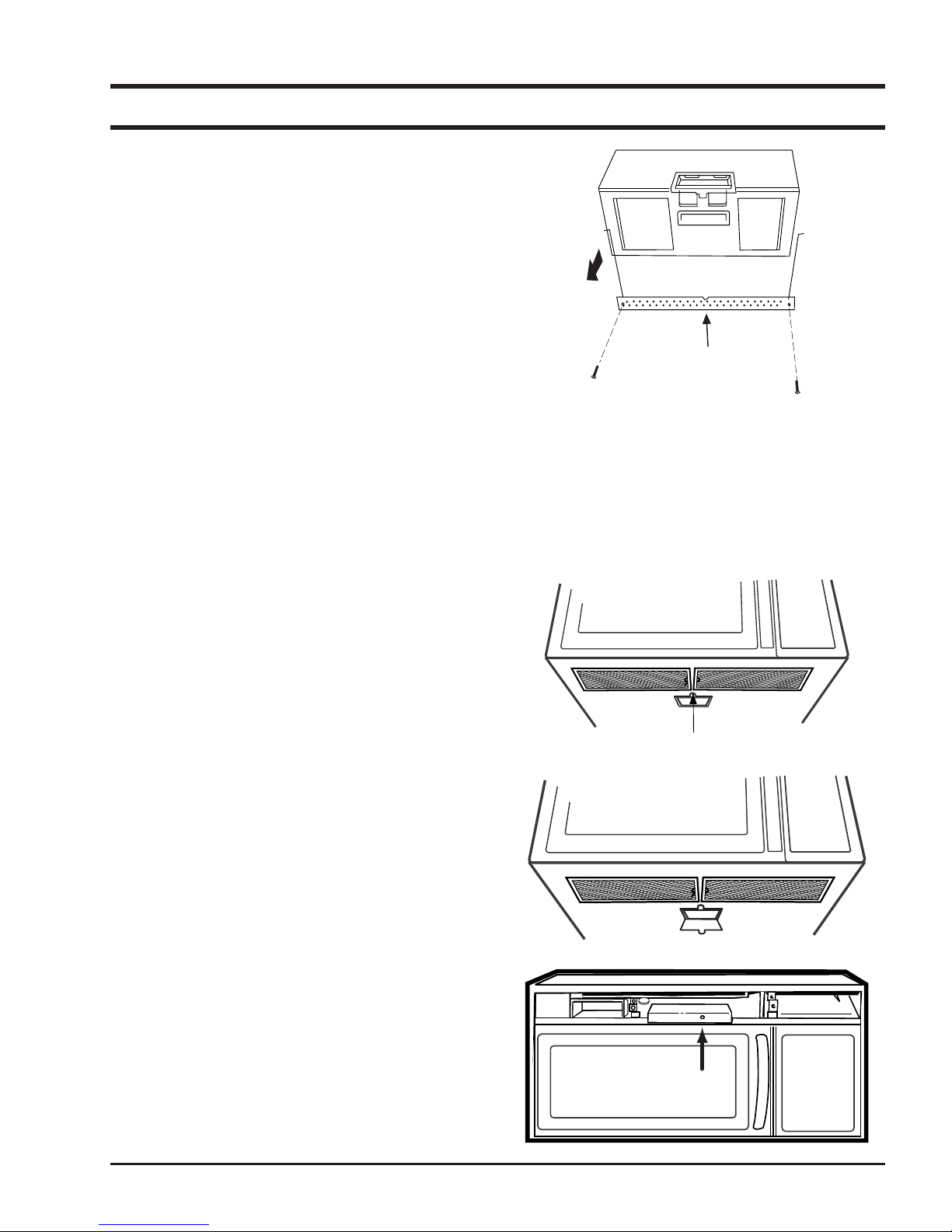
Charcoal Filter
Reusable Grease Filters
Screws
Remove 2 grille screws to remove the grill
3-5 REUSABLE GREASE FILTERS
The metal filter trap grease released by foods on
the cooktop. They also prevent flames from foods
on the cooktop from damaging the inside of the
microwave.
For this reason, the filters must ALWAYS be in
place when the hood the vent fan is used. The
grease filter should be cleaned once a month, or
as needed.
REMOVING CHARCOAL FILTER
To remove the charcoal filter, disconnect power
at the main fuse or circuit breaker panel or pull
the plug. Remove the top grille by removing the 2
screws that hold it in place.
Slide the filter towards the filter towards the front
of the oven and remove it.
AUTOMATIC FAN
An automatic fan feature protects the microwave
from too much heat rising from the cooktop below
it. If you have turned the fan on you may find that
you cannot turn it. The fan will automatically turn
off when the internal parts are cool. If may stay
on for 30 minutes or more after the cooktop and
microwave controls are turned off.
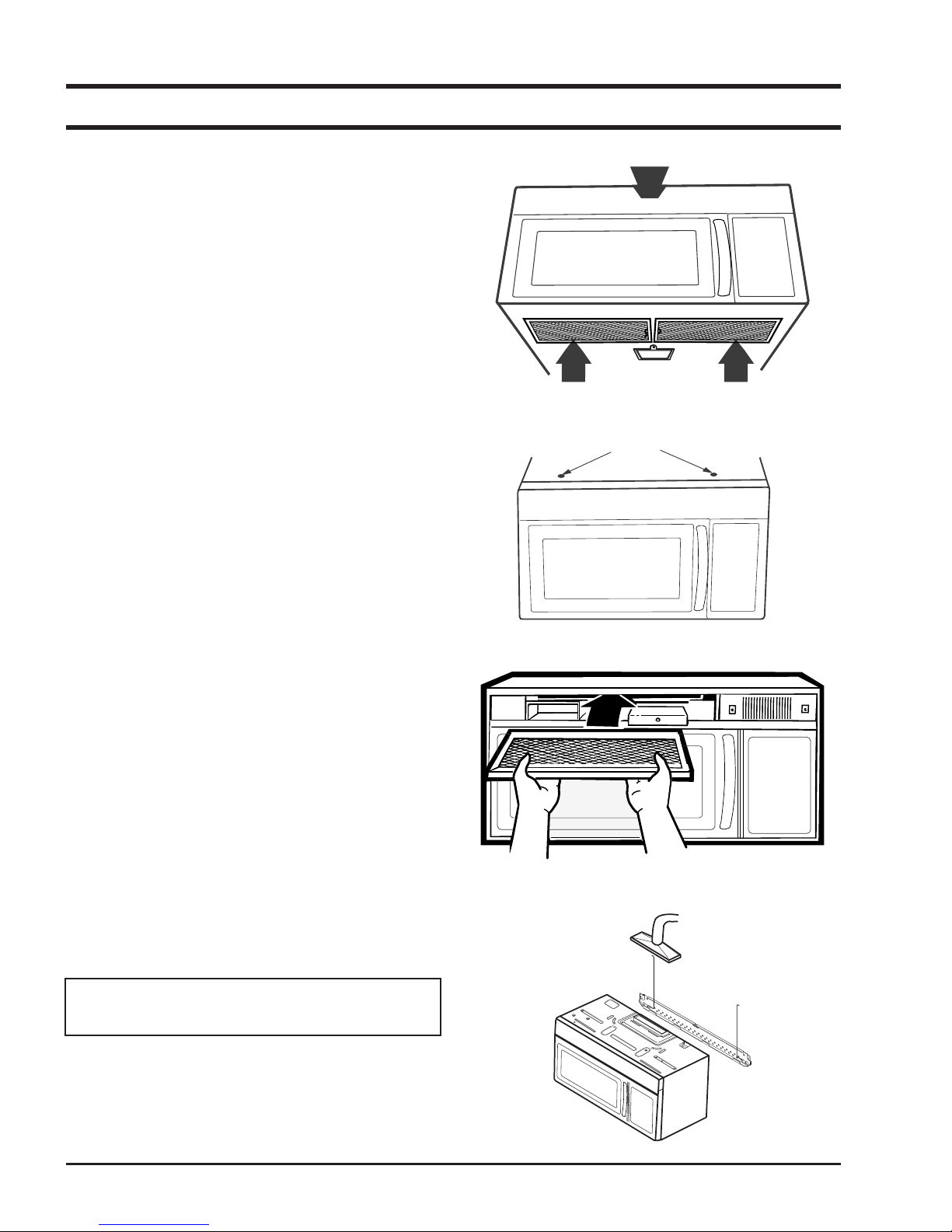
GRILLE REMOVAL
The top full-width grille is removable for service
to some components, such as : oven light, cavity
T.C.O, vent motor capacitor and fuse.
TO REMOVE GRILLE :
1. Disconnect oven power.
2. Remove screws (2) from grille outer case.
3. Lift off grille.
REMOVING OVEN FROM WALL
(2 PEOPLE REQUIRED)
Oven is hooked on metal tabs at bottom of wall
mounting plate and fastened to cabinet by (3) top
cabinet bolts.
1. Disconnect power cord. Top vented models-
2. Remove (3) top cabinet bolts.
3. Pull unit forward slowly providing adequate
CAUTION : Oven weights 63.1 lbs. Requires 2
people for removal.
disconnect duct and remove damper assembly.
support to prevent dropping unit during removal of last top cabinet bolts.
- 8 -
4. Disassembly and Reassembly
4-1 Replacement of Magnetron, Motor Assembly and Lamp
Remove the magnetron including the shield case, permanent magnet, choke coils and capacitors
(all of which are contained in one assembly).
1. Disconnect all lead wires from the magnetron and lamp.
2. Remove a screw securing air cover.
3. Remove the air cover.
4. Remove screws securing the magnetron to the wave guide.
5. Take out the magnetron very carefully.
6. Remove tow from the back panel of fan motor assembly.
7. Take out the fan motor assembly.
8. Remove the oven lamp by rotating to pull out from hole of air cover.
NOTE1: When removing the magnetron, make sure that its antenna does not hit any adjacent parts, or it may
be damaged.
NOTE2: When replacing the magnetron, be sure to remount the magnetron gasket in the correct position and
make sure the gasket is in good condition.
4-2 Replacement of High Voltage Transformer
1. Discharge the high voltage capacitor.
2. Disconnect all the leads.
3. Remove the mounting bolts.
4. Reconnect the leads correctly and firmly.
Servicemen should remove their watches whenever working close to or replacing the magnetron.
PRECAUTION
There exists HIGH VOLTAGE ELECTRICITY with high current capabilities in the circuits of the HIGH
VOLTAGE TRANSFORMER secondary and filament terminals. It is extremely dangerous to work on or near
these circuits with the oven energized.
DO NOT measure the voltage in the high voltage circuit including filament voltage of magnetron.
PRECAUTION
- 9 -
 Loading...