

Page 1
7. Level 2 Repair
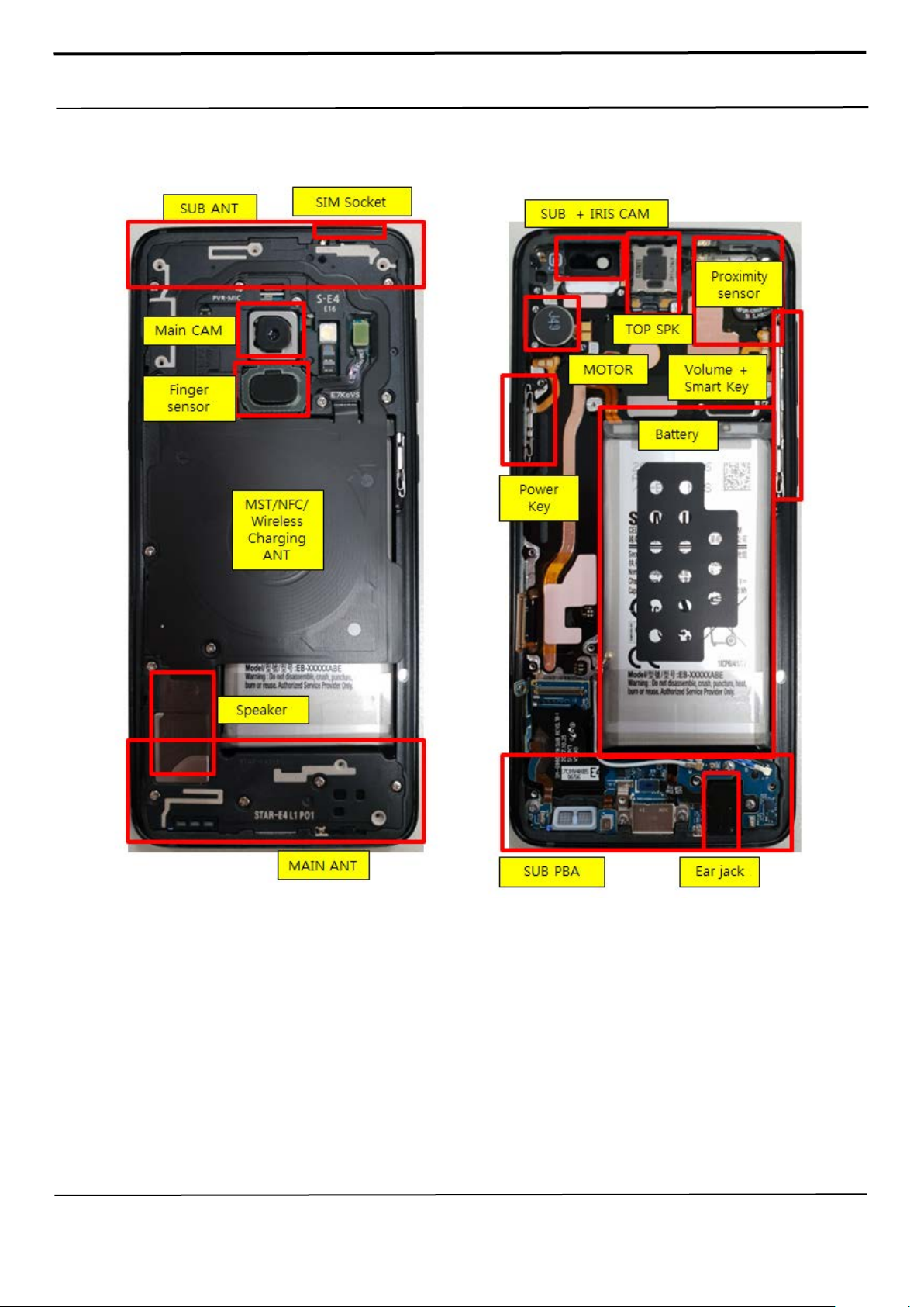
7-1. Components on the Rear Case
Confidential and pr oprietary-the c ontents in this ser vice guide subject to change wi thout prior noti ce
Distribution, transmission, or infringement of any content or data from this document without Samsung’s written authorization is strictly prohibited.
Page 2
7. Level 2 Repair
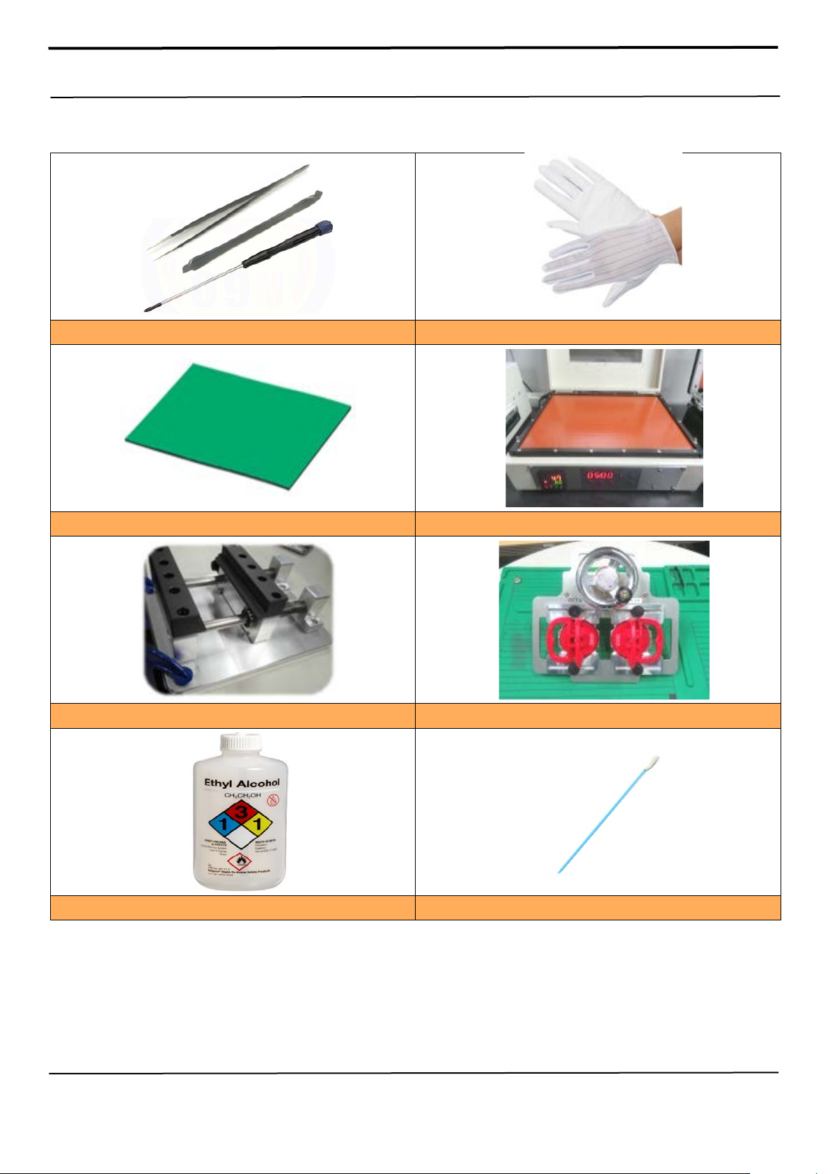
Anti-static Mat
Hot Plate
OCTA Disassembly Upper
7-2. Pre-requisite
Tweezers / Disass'y Stick / Screw Driver
A OCTA Disassembly Holder
Anti-static Gloves
Confidential and pr oprietary-the c ontents in this ser vice guide subject to change wi thout prior noti ce
Distribution, transmission, or infringement of any content or data from this document without Samsung’s written authorization is strictly prohibited.
Ethyl Alcohol Cotton Swab
Page 3
7. Level 2 Repair
BOM description & part
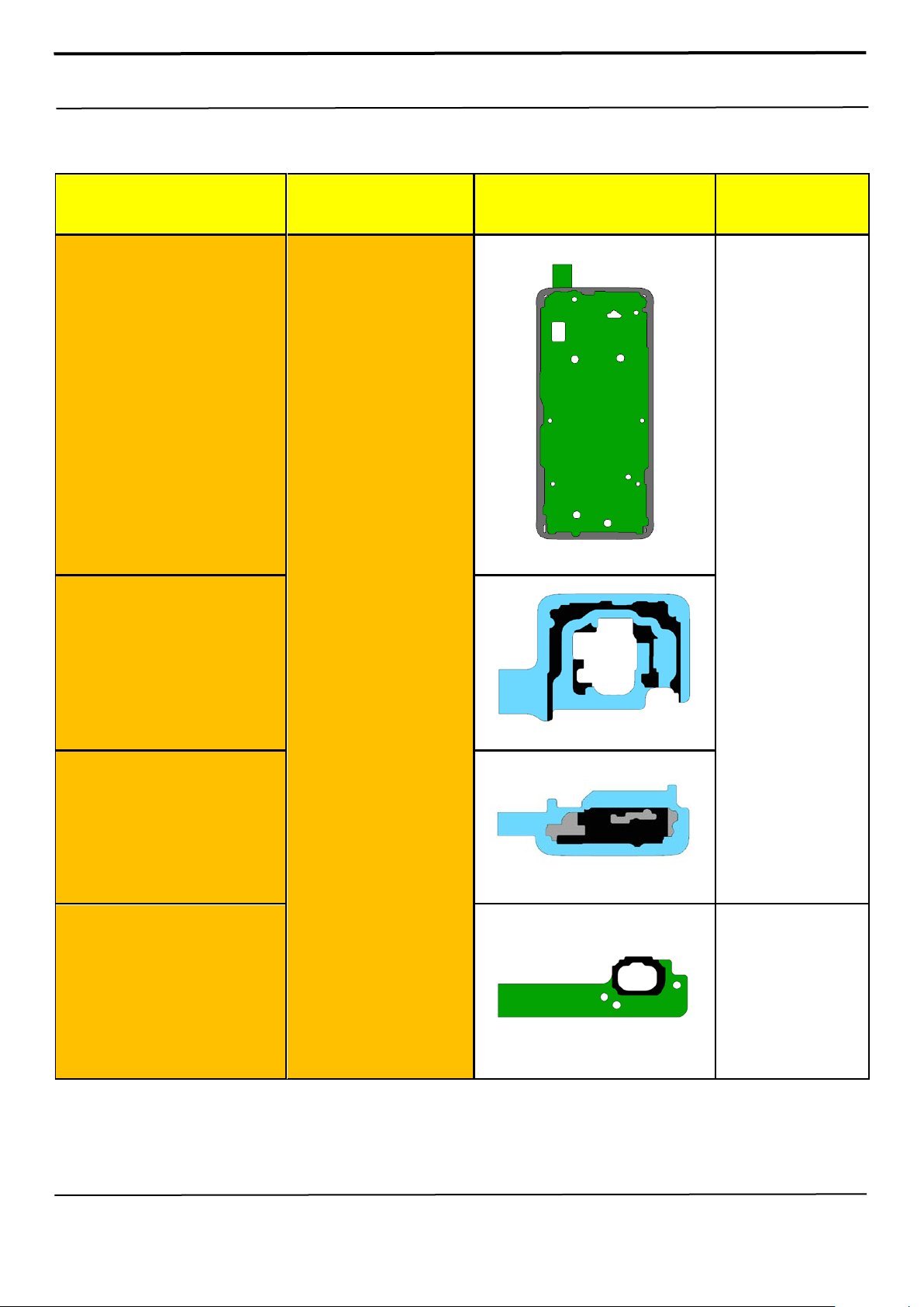
7-3. Parts which must be changed after repair
code
A/S-SVC TAPE BG WP
OUTER
(Common)
[GH81-15404A]
A/S-SVC TAPE BG INNER
NA (CHN/LA)
[GH81-15406A]
KIT CODE Image Remarks
Replace for
Back Glass repair
A/S REWORK KITSM-G9600/G9608
(CHN/LA)
[GH82-15974A]
A/S-SVC TAPE BG INNER
BTM NA (USA,CHN)
[GH81-15415A]
TAPE FING ER SENSOR
WP
[GH02-15815A]
Replace for Back
Glass
Or Finger print
sensor repair
Confidential and pr oprietary-the c ontents in this ser vice guide subject to change wi thout prior noti ce
Distribution, transmission, or infringement of any content or data from this document without Samsung’s written authorization is strictly prohibited.
Page 4
7. Level 2 Repair
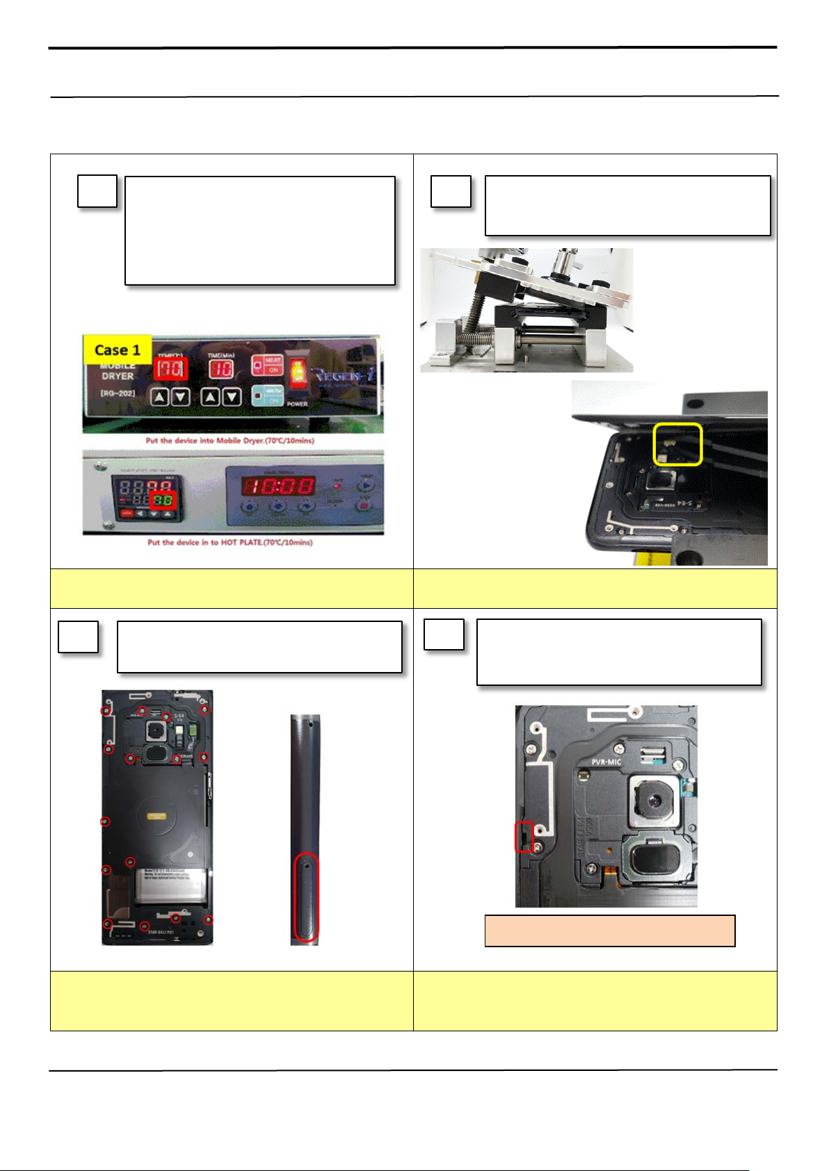
Rea r To p disassemble hole.
Please confirm the heating condition
7-4. Disassembly
1
Put the device in the chamber as following
below heating condition
- SOC 68%↓: 70℃/10~20 minute
- SOC 68%↑: 70℃/10~20 minute
※
released lastly, and follow it.
2
Detach the Back Glass. And Finger sensor
1) Detach the left side of Back glass
2) Detach the Finger sensor connector
※ C a uti o n
Be care of scratch
3
Unscrew 15 Point and disassemble SIM Tray
from device
※ C a u ti o n
Be care of scratch
4
Disassemble Upper Rear.
(Use disassemble hole left/right side of Rear to
detach it)
※ C a u ti o n
Be care of Rear damage
Confidential and pr oprietary-the c ontents in this ser vice guide subject to change wi thout prior noti ce
Distribution, transmission, or infringement of any content or data from this document without Samsung’s written authorization is strictly prohibited.
※ C a u ti o n
1) Be care of scratch
2) Be care of Rear and connector damage
Page 5

7. Level 2 Repair
3) Be careful not to damage the PBA
Finally Disassemble Rear of bottom side.
detach it)
5
※ C a u ti o n
1) Be care of scratch
2) Be care of Rear and connector damage
(Use disassemble hole right side of Rear to
7
2 coaxial cable, Battery connect and the other
connectors. (7 Point)
6
Unscrew PBA 1points.
※ C a u ti o n
Be careful not to damage the PBA
Detach SUB PBA connector
8
※ C a u ti o n
1) Be care of scratch
2) Be care of connector/cable damage
Confidential and pr oprietary-the c ontents in this ser vice guide subject to change wi thout prior noti ce
Distribution, transmission, or infringement of any content or data from this document without Samsung’s written authorization is strictly prohibited.
※ C a u ti o n
1) Be care of FPCB damage
2) Be care of SUB PBA connector
Page 6

7. Level 2 Repair
Unscrew SUB PBA 5points
Detach other components.
9
10
※ C a u ti o n
Be care of several kinds of damage
※ C a u ti o n
Be careful not to damage the SUB PBA
11
Detach Ear Jack
12
Detach SUB PBA (1/4)
※ C a u ti o n
1) Be care of SUB PBA damage
2) Be care of Ear jack connector
Confidential and pr oprietary-the c ontents in this ser vice guide subject to change wi thout prior noti ce
Distribution, transmission, or infringement of any content or data from this document without Samsung’s written authorization is strictly prohibited.
※ Caution
Be care of SUB PBA damage
Page 7

7. Level 2 Repair
13
※ C a u ti o n
Be care of SUB PBA damage
Detach SUB PBA (2/4)
14
※ Caution
Be care of SUB PBA damage
Detach SUB PBA (3/4)
15
※ C a u ti o n
Be care of SUB PBA damage
Detach SUB PBA (2/4)
Confidential and pr oprietary-the c ontents in this ser vice guide subject to change wi thout prior noti ce
Distribution, transmission, or infringement of any content or data from this document without Samsung’s written authorization is strictly prohibited.
Page 8

7. Level 2 Repair
7-5. Assembly
1
※ Caution
Be care of coaxial cable damage
3
Attach SUB PBA and Ear jack on Front.
Attach components on Front.
(TOP SPK, Sensor FPCB, Motor)
2
※ C a u ti o n
Be care of chip damage nearby screw point.
Screw 5point in SUB PBA.
4
Attach PBA assy In Front Assy.
(PBA+ Front)
※ Caution
1) Be care of FPCB damage and tilt
2) Be care of press power/time
Confidential and pr oprietary-the c ontents in this ser vice guide subject to change wi thout prior noti ce
Distribution, transmission, or infringement of any content or data from this document without Samsung’s written authorization is strictly prohibited.
※ Caution
1) Be care of Push SUB PBA connector.
2) Be care of components FPCB.
Page 9

7. Level 2 Repair
Attach Front CAM and Iris CAM on PBA.
Assemble the TOP+MID REAR Assy in
sequence.
5
※ Caution
Be care of press power/time
6
※ Caution
Be care of FPCB and Y-OCTA damage
Attach 2 coaxial cable, Battery connect and
the other connectors. (8 Point)
7
Assemble the Bottom REAR in sequence.
8
※ Caution
Be care of scratch and REAR damage
Confidential and pr oprietary-the c ontents in this ser vice guide subject to change wi thout prior noti ce
Distribution, transmission, or infringement of any content or data from this document without Samsung’s written authorization is strictly prohibited.
※ Caution
Be care of scratch and REAR damage
Page 10

7. Level 2 Repair
Attach the back glass inner tape on the
backglass
Unscrew 15 Point and disassemble SIM Tray
9
from device
* Screw Torque : 1.3kgf
10
Attach the finger sensor on the REAR and
Assemble the finger sensor on the PBA
※ Caution
Be care of scratch and REAR damage
11
※ C a u ti o n
Be care of scratch and tilt.
12
Attach the finger tape on the back glass.
※ C a u ti o n
Be care of scratch and tilt.
Confidential and pr oprietary-the c ontents in this ser vice guide subject to change wi thout prior noti ce
Distribution, transmission, or infringement of any content or data from this document without Samsung’s written authorization is strictly prohibited.
※ C a u ti o n
Be care of scratch and tilt.
Page 11

7. Level 2 Repair
Attach the back glass outside tape on the rear
13
case
14
Attach the back glass on the REAR side.
※ C a u ti o n
Be care of scratch and tilt.
15
Press Back Glass.
Pressing force : 1 N
Pressing time : 1 minute
※ Caution
Be care of scratch and tilt.
※ Caution
Be care of scratch.
Confidential and pr oprietary-the c ontents in this ser vice guide subject to change wi thout prior noti ce
Distribution, transmission, or infringement of any content or data from this document without Samsung’s written authorization is strictly prohibited.
 Loading...