

Samsung SM-G850 Disassembly & Reassembly
7.
7-1.
Level
Repair
2
Disassembly and assembly Instructions
7-1-1.
1
※
1)
2)
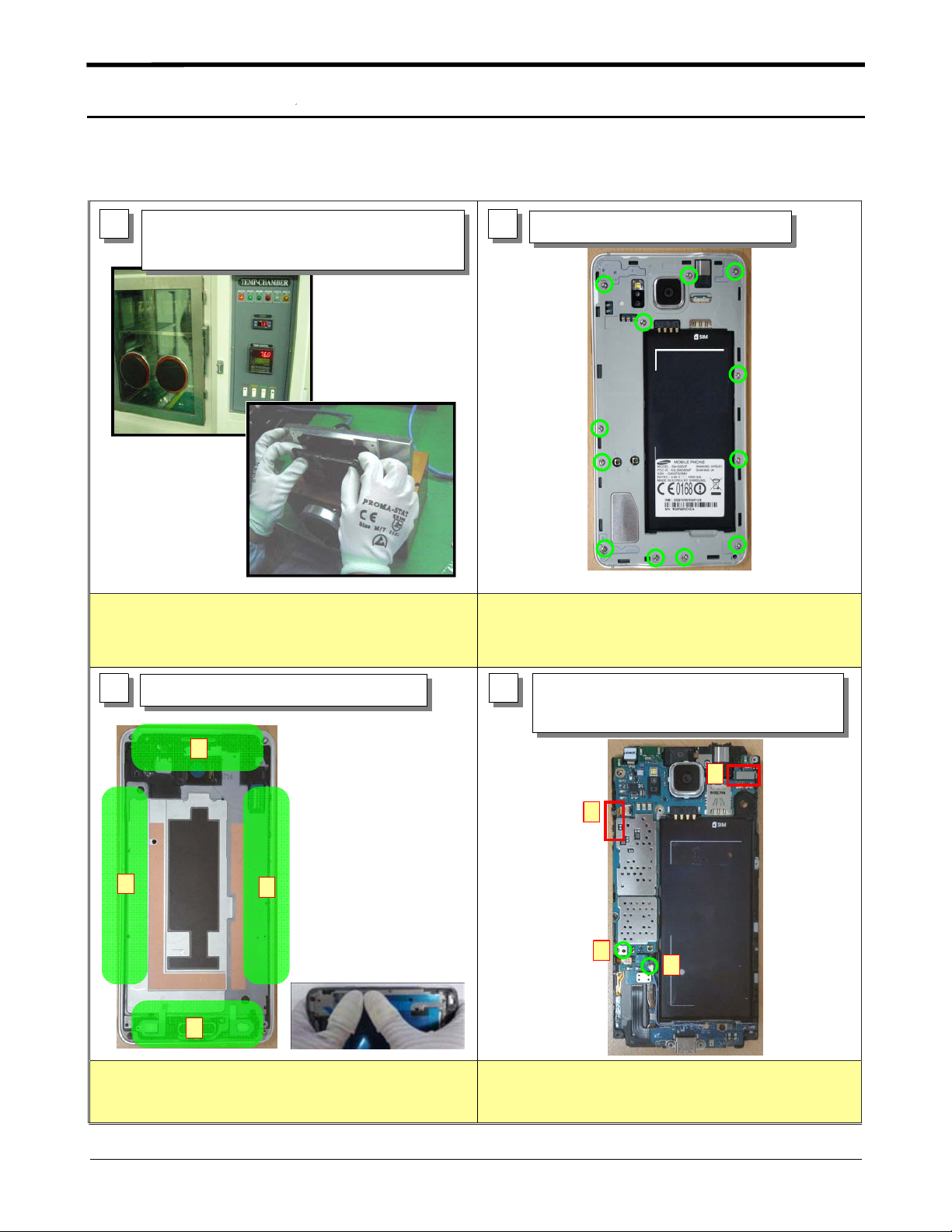
Disassembly
Displace the temperature chamber for
1)
minute
30
Detach the OCTA using Vaccum Jig
2)
Caution
Before disassembling, Use heating chamber.
Be care of scratch and molding damage.
2
Caution
※
1)
Unscrew the12points.
1)
Be care of scratch and molding damage.
3 4
※
1)
2)
Detach the Bracket Assay from Rear.
1)
4
3
1
2
Caution
Be care of damage to Connector.
It pushes this part at disassembly, and lift it
Unscrew the1points.
1)
Disassemble coaxial cable
2)
3) Disassemble Connector and Power Key FPCB
3
3
1
Caution
※
Be care of damage to the SUB PCB
1)
2
Connector, coaxial cable.
7-1
Confidential and proprietary-the contents in this service guide subject to change without prior notice.
Distribution, transmission, or infringement of any content or data from this document without Samsung’swritten authorization is strictly prohibited.
Level2Repair
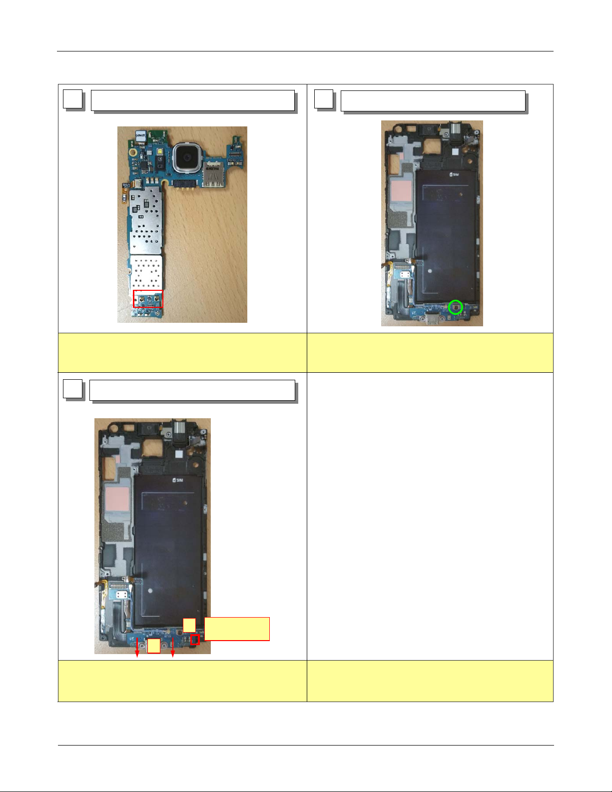
5 6
※
1)
Separate the PBA from Bracket.
1)
Caution
Be care of scratch and antenna contact
damage.
7
Separate the Sub PBA from Bracket.
1)
Unscrew the1points.
1)
Caution
※
Be care of scratch and molding damage.
1)
Diassemble
1
Point
2
Caution
※
Be care of damage to Bracket.
1)
At disassemble point, lift it.
2)
7-2
Confidential and proprietary-the contents in this service guide subject to change without prior notice.
Distribution, transmission, or infringement of any content or data from this document without Samsung’swritten authorization is strictly prohibited.
 Loading...