

Samsung SMG-3000 Installation Manual

SAMSUNG
SMG-3000
(MINI DCS GATEWAY)
INSTALLATION
MANUAL

Publication Information
Samsung Telecoms reserves the right without prior notice to revise information in this publication
for any reason.
Samsung Telecoms also reserves the right without prior notice to make changes in design or components of equipment as engineering and manufacturing may warrant.
Disclaimer
Samsung Telecoms is not responsible for errors or problems arising from customers not installing,
programming or operating their Samsung systems as described in this manual.
Copyright 2001
Samsung Telecoms (U.K.) Limited
All rights reserved. No part of this manual may be reproduced in any form or by any means –
graphic, electronic or mechanical, including recording, taping, photocopy or information retrieval
system – without express written permission of the publisher of this material.
Part No.:12610 Version 1.0

EU Declaration of Conformity (RTTE)
Samsung Electronics Co, Ltd.
259 Gongdan-Dong, Gumi -City Kyungbuk, Korea, 730-030
(factory name, address)
declare under our sole responsibility that the product
Digital Telephone Exchange model "SMG-3000"
to which this declaration relates is in conformity with
RTTE Directive 1999/5/EC ( Annex II )
Low Voltage Directive 73/23/EEC
EMC Directive 89/336/EEC:92/31/EEC
By application of the following standards
EN55022: 1998*
....................................................................................................................................................
EN61000-3-2: 1995 INC. A1/A2: 1998
....................................................................................................................................................
EN61000-3-3: 1995
....................................................................................................................................................
EN55024: 1998
....................................................................................................................................................
AS/NZS3548: 1995
....................................................................................................................................................
CTR3/A1 (Commission Decision 98/515/EC)
....................................................................................................................................................
CTR4/A1 (Commission Decision 98/520/EC)
....................................................................................................................................................
CTR21/A1 (Commission Decision 98/482/EC)
....................................................................................................................................................
(Manufacturer)
Samsung Electronics Co., Ltd
259, Gongdan-Dong, Gumi-City
Kyungbuk, Korea 730-030
Sung-Chul Hong / General Manager
................................................. .................................................................................
(place and date of issue) (name and signature of authorized person)
(Representative in the EU)
Samsung Electronics Euro QA Lab.
Blackbushe Business Park
Saxony Way, Yateley, Hampshire
GU46 6GG, UK
In-Seop Lee / Manager
................................................. ...............................................................................
(place and date of issue) (name and signature of authorized person)
2001-05-22
2001-05-22
SC Hong
IS Lee

Intended Use
This telephone system is intended to provide the user with voice communication between the system extensions and
connection to the public switched telephone network by digital or analogue links.
The telephone system may be provided with the ability to communicate with local computer networks to provide CTI
functions and features. In this case, it is capable of passing information to the computer network via a specified link.
The system is powered by mains voltage and can optionally be powered by batteries. Details of all connections and
power arrangements are provided in the instructions for use. It should not be used in any other way.

i
Contents
Chapter 1 Introduction
SMG-3000 System Functions....................................................... 1-1
System Features .......................................................................... 1-1
Cost-effective Design Features......................................................................... 1-1
Flexible Modules............................................................................................... 1-1
Future Expansion.............................................................................................. 1-2
Convenient Maintenance and Repair ................................................................ 1-2
Chapter 2 SMG-3000 System Setup
System Structure.......................................................................... 2-1
System Rack.....................................................................................................2-1
Card Types ....................................................................................................... 2-2
Chapter 3 Installing the SMG-3000 System
Installation Procedure Checklist.................................................... 3-1
Basic Requirements ..................................................................... 3-1
Safety ...............................................................................................................3-1
Environmental Conditions ................................................................................. 3-1
Grounding the System ......................................................................................3-2
Input Power Supply........................................................................................... 3-2
Installing Cables................................................................................................3-2
Arranging Space for Installation ........................................................................ 3-2
Unpacking the System.................................................................. 3-2
Connecting the Power and Battery Cables ................................... 3-3
Installing Cards............................................................................. 3-5
Rack Slots......................................................................................................... 3-5
Procedure ......................................................................................................... 3-5
Connecting Cables to Subscriber Cards....................................... 3-8
Preparing the Cable.......................................................................................... 3-8
Connecting the Cable........................................................................................3-8
Installing the Storage Battery...................................................... 3-10
Precautions..................................................................................................... 3-10

ii Contents
Chapter 4 Connecting Peripherals
The I/O Ports................................................................................ 4-1
Connecting the PC for MAP.......................................................... 4-2
Connecting to a 25-pin Serial Port Using an RS-232C Cable............................ 4-2
Connecting to the I/O 4 (LAN) Port.................................................................... 4-3
Connecting the PC for PMS.......................................................... 4-4
Connecting a Serial Printer........................................................... 4-5
Chapter 5 System Checking and Operation
Before Operation .......................................................................... 5-1
Checking Operating Conditions.........................................................................5-1
Checking Safety Conditions .............................................................................. 5-1
Starting the System ...................................................................... 5-1
Checking System Functions ......................................................... 5-3
Checking Basic Telephone Functions ............................................................... 5-3
Checking the Attendant Console....................................................................... 5-4
Checking Operation of Peripherals....................................................................5-5
Shutting Down the System ........................................................... 5-5
Chapter 6 SMG-3000 System Maintenance
and Repair
Exchanging Subscriber Cards ...................................................... 6-1

1–1
Chapter 1 Introduction
This chapter describes the various functions of the SMG-3000 telephone system.
SMG-3000 System Functions
The SMG-3000 system is a small-scale version of the DCS Gateway System. It combines voice and data
(ISDN) communications, creating a new type of telephone exchange system. It also offers the Voice over
Internet (VoIP) protocol using the Internet Telephone (ITM) interface. Both the system hardware and software operate on a modular design so that the system can be easily expanded and new modules added.
The SMG-3000 system provides an integrated system offering various services when connected to other
equipment such as Automatic Call Distribution (ACD) and voice mail systems (VMS). As networks digitalise and increase in speed, the ability of the SMG-3000 system to provide excellent digital data transmission
is highlighted.
System Features
The SMG-3000 system offers:
• The latest VoIP technology.
• The latest microprocessor technology.
• Improved VLSI circuit technology.
• Custom IC design technology.
• System diagnostics program.
Cost-effective Design Features
The SMG-3000 system is designed to be cost-effective by:
• using optimum card component density at the most competitive price;
• minimising power consumption using CMOS technology components;
• installing components more effectively on the control card;
• expanding system functions more conveniently and cheaply;
• providing flexible control functions for long-distance calls and cost management functions such as con-
trol function by class of service (COS);
• providing the Call Detail Recording function which analyses system usage and call costs.
Flexible Modules
The SMG-3000 system operates on a modular basis so that you can easily add new hardware, such as cards,
or software. There are a number of user (subscriber) slots into which you can insert cards such as a data card,
subscriber cards and trunk card.
The system supports four types of trunk card that allow easy expansion of the system circuit capacity.
• GLOOP2 TRK: 16-port loop-start trunk card
• G4W E&M: 6-port 4-wire E&M circuit
• PRI4: ISDN primary rate interface (30 ports)
• BRI: 8-port basic rate interface

1–2 Introduction
Future Expansion
You do not need to invest a lot of money and effort to add new functions to the SMG-3000 system. This is
because the system offers the following functions.
• Connection of digital phones providing a variety of functions through the phone line.
• PRI and BRI cards that connect to ISDN.
• S-INTERFACE linking to an ISDN terminal.
• Supports Computer Telephony Integration (CTI) to provide a number of services by connecting a PC to
the system.
Convenient Maintenance and Repair
The system provides the following functions for more convenient maintenance and repair.
MAP
MAP is the SMG-3000 operating software used to maintain and repair the system. It runs on the MAP PC
and can access, change and control all system information.
Diagnostic Function
If the SMG-3000 system malfunctions, you are made immediately aware because the system always performs a diagnostic routine and displays the results on a PC or printer.
2–1
Chapter 2 SMG-3000 System Setup
This chapter describes how the SMG-3000 system is structured and looks at the cards that can be inserted
into the system rack. This manual does not describe the cards in any detail, nor how to connect telephones to
the cards. For this information you are referred to the DCS Gateway documentation CD-ROM supplied with
your system. Only details specific to the SMG-3000 system are included in this guide.
System Structure
First, let’s look at the rack structure of the SMG-3000 system and its components.
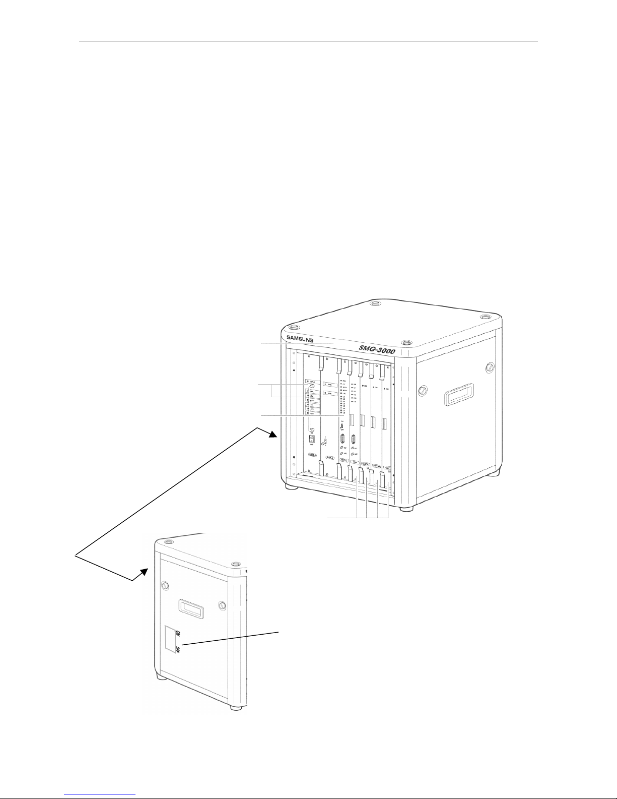
System Rack
The system rack comprises a shelf with slots into which power cards, a control card, and a number of subscriber cards can be inserted. There is a power on/off switch on the left-hand side of the rack.
Rack
Control card
Power on/off
switch
Power cards
Subscriber cards
2–2 System Setup
Card Types
Power Cards
The power cards comprise:
• The RCMP-D (power) card located in the power slot farthest to the left of the shelf which supplies the
necessary power to all cards in the shelf.
• The
RGPS-K (ringer) card providing the ring signal and the message-waiting signal to the receiver con-
nected to the subscriber card.
Control Card
The MCPU2 (control) card is the main processor card for the system and initialises the system when it starts
operating. It also provides a clock to each card, stores and searches data, controls data transmission to peripheral devices, and checks and tests the condition of cards. This card:
• acts as the interface between different subscriber cards;
• supplies the system clock for SMG-3000 network synchronisation, and the system tone source;
• provides the I/O interface.
Subscriber Cards
The subscriber cards provide various services to subscribers. The SMG-3000 system can hold a maximum of
four subscriber cards in the shelf.
For different service types, there are relevant subscriber cards: analogue card, digital card, ISDN card and
service card.
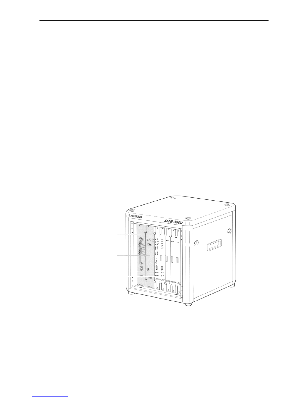
The following illustration shows the RCMP-D card, the RGPS-K card and the MCPU2 card.
RCMP-D card (power)
RGPS-K card (ringer)
MCPU2 card (control)

3–1
Chapter
3
Installing the SMG-3000 System
This chapter provides instructions on installing the SMG-3000 system. First, the general procedures are discussed, together with the conditions necessary for installation. Then, it discusses the detailed procedures for
installing the rack and inserting the cards. Finally, it explains how to connect the storage battery to supply
emergency power to the system if the mains power fails.
Installation Procedure Checklist
The following steps should be taken to install the SMG-3000 system.
1. Ensure there is sufficient room for the system in the required location.
2. Carry the boxed system to the location and unpack all boxes.
3. Install the rack.
4. Connect the power cable.
5. Set the jumper on the card(s) you want to install and insert the card(s) in the rack.
6. Connect the user cables.
7. Connect the battery.
8. Install the Maintenance and Administration Program (MAP) system.
9. Start the system.
10. Install the system software.
11. Install peripherals (printer, etc).
12. Check the basic system functions.
13. Perform a final test.
To install the rack, cards and battery, read this chapter. To install peripherals, read Chapter 4, Connecting
Peripherals. To start and test the basic system functions, read Chapter 5, System Checking and Operation.
Note: For information on setting card jumpers and installing the MAP and system software, refer to the DCS Gateway
documentation CD-ROM supplied with your system.
Basic Requirements
The following sections describe the optimal conditions and requirements for the room where installation is to
be carried out, to ensure that the SMG-3000 system performs to its design capabilities
.
Safety
• Explosive gas or other flammable items must not be placed inside the room where the system is to be
installed.
• Unauthorised personnel must be kept out.
• Inspections of the electric wiring, ground line, voltage and frequency should be done in advance.
• When installed, do not place other items of equipment on top of the system rack.
Environmental Conditions
• The room must maintain a consistent temperature and humidity.
- Temperature: 0 – 45oC
- Relative Humidity: 10 – 90% (non-condensing)
• The room should be kept cool and not be exposed to direct sunlight.
• During and after installation of the SMG-3000 system, keep the room clean and dust free.
• Ensure there are adequate cable conduits available for keeping cables safely covered.
 Loading...