


SmartServer 370
User’s Guide

© Copyright SAMSUNG Electronics co., LTD . . All rights reserved.

Contents
Safety ............................v
Chapter 1. Introducing the SAMSUNG SmartServer 370 .........1
Related publications .......................2
Notices and statements used in this book ...............3
Features and specifications.....................4
What your server offers ......................5
Reliability, availability, and serviceability features .............7
Active Memory .........................8
Memory scrubbing and Memory ProteXion ..............8
Memory mirroring .......................8
IBM Director ..........................8
The UpdateXpress program ....................9
Server controls, LEDs, and power ..................10
Front view .........................10
Rear view..........................12
Server power features ......................14
Turning on the server .....................14
Turning off the server .....................15
Chapter 2. Configuring the server .................17
Using the Configuration/Setup Utility program .............18
Starting the Configuration/Setup Utility program ............18
Configuration/Setup Utility menu choices ..............18
Remote console redirection ...................23
Passwords .........................24
Using the ServerGuide Setup and Installation CD ............25
ServerGuide features .....................25
Setup and configuration overview .................26
System Partition .......................27
Typical operating-system installation ................27
Setting up or updating multiple servers ...............28
Installing your operating system without ServerGuide..........29
Configuring the Gigabit Ethernet controller...............29
Using the Extensible Firmware Interface boot manager ..........29
Using the integrated system management firmware update utility program . . . 30
Using the LSI Logic Configuration Utility program ............31
Starting the LSI Logic Configuration Utility program ..........31
Formatting a SCSI hard disk drive.................31
Creating a mirrored pair of SCSI hard disk drives ...........32
Setting up the Remote Supervisor Adapter...............32
Remote Supervisor Adapter features ................32
Setup requirements ......................32
Using the documentation ....................33
Cabling and configuring the Remote Supervisor Adapter.........33
Using the ASM interconnect network ................43
Using the PXE boot agent utility program ...............50
Starting the PXE boot agent utility program .............50
PXE boot agent utility menu choices ................50
Using ServeRAID Manager ....................51
Configuring the controller ....................51
Viewing the configuration ....................56
Getting assistance ......................57
© Copyright SAMSUNG Electronics co., LTD. All rights reserved. iii

Configuring scalable partitions ...................58
Creating a scalable partition ...................59
Deleting a scalable partition ...................60
iv User’s Guide
Safety
Before installing this product, read the Safety Information.
Antes de instalar este produto, leia as Informações de Segurança.
Pred instalací tohoto produktu si prectete prírucku bezpecnostních instrukcí.
Læs sikkerhedsforskrifterne, før du installerer dette produkt.
Lees voordat u dit product installeert eerst de veiligheidsvoorschriften.
Ennen kuin asennat tämän tuotteen, lue turvaohjeet kohdasta Safety Information.
Avant d’installer ce produit, lisez les consignes de sécurité.
Vor der Installation dieses Produkts die Sicherheitshinweise lesen.
Prima di installare questo prodotto, leggere le Informazioni sulla Sicurezza.
Les sikkerhetsinformasjonen (Safety Information) før du installerer dette produktet.
Antes de instalar este produto, leia as Informações sobre Segurança.
v

Antes de instalar este producto, lea la información de seguridad.
Läs säkerhetsinformationen innan du installerar den här produkten.
Statement 1:
DANGER
Electrical current from power, telephone, and communication cables is
hazardous.
To avoid a shock hazard:
v Do not connect or disconnect any cables or perform installation,
maintenance, or reconfiguration of this product during an electrical
storm.
v Connect all power cords to a properly wired and grounded electrical
outlet.
v Connect to properly wired outlets any equipment that will be attached to
this product.
v When possible, use one hand only to connect or disconnect signal
cables.
v Never turn on any equipment when there is evidence of fire, water, or
structural damage.
v Disconnect the attached power cords, telecommunications systems,
networks, and modems before you open the device covers, unless
instructed otherwise in the installation and configuration procedures.
v Connect and disconnect cables as described in the following table when
installing, moving, or opening covers on this product or attached
devices.
To Connect: To Disconnect:
1. Turn everything OFF.
2. First, attach all cables to devices.
3. Attach signal cables to connectors.
4. Attach power cords to outlet.
5. Turn device ON.
1. Turn everything OFF.
2. First, remove power cords from outlet.
3. Remove signal cables from connectors.
4. Remove all cables from devices.
vi User’s Guide
Statement 2:
CAUTION:
When replacing the lithium battery, use an equivalent type battery recommended
by the manufacturer. If your system hasa module containing a lithium battery,
replace it only with the same module type made by the same manufacturer.
The battery contains lithium and can explode if not properly used, handled,
or disposed of.
Do not:
v Throw or immerse into water
v Heat to more than 100°C (212°F)
v Repair or disassemble
Dispose of the battery as required by local ordinances or regulations.
Statement 3:
CAUTION:
When laser products (such as CD-ROMs, DVD drives, fiber optic devices, or
transmitters) are installed, note the following:
v Do not remove the covers. Removing the covers of the laser product could
result in exposure to hazardous laser radiation. There are no serviceable
parts inside the device.
v Use of controls or adjustments or performance of procedures other than
those specified herein might result in hazardous radiation exposure.
DANGER
Some laser products contain an embedded Class 3A or Class 3B laser
diode. Note the following.
Laser radiation when open. Do not stare into the beam, do not view directly
with optical instruments, and avoid direct exposure to the beam.
Safety vii
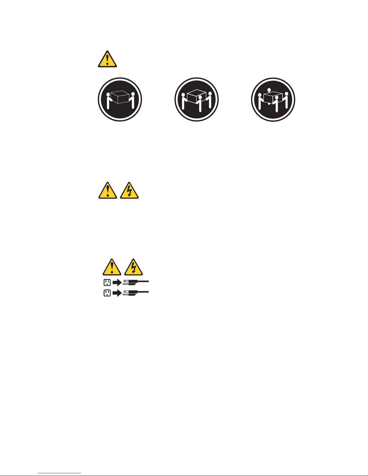
Statement 4:
≥ 18 kg (39.7 lb) ≥ 32 kg (70.5 lb) ≥ 55 kg (121.2 lb)
CAUTION:
Use safe practices when lifting.
Statement 5:
CAUTION:
The power control button on the device and the power switch on the power
supply do not turn off the electrical current supplied to the device. The device
also might have more than one power cord. To remove all electrical current
from the device, ensure that all power cords are disconnected from the power
source.
1
2
viii User’s Guide
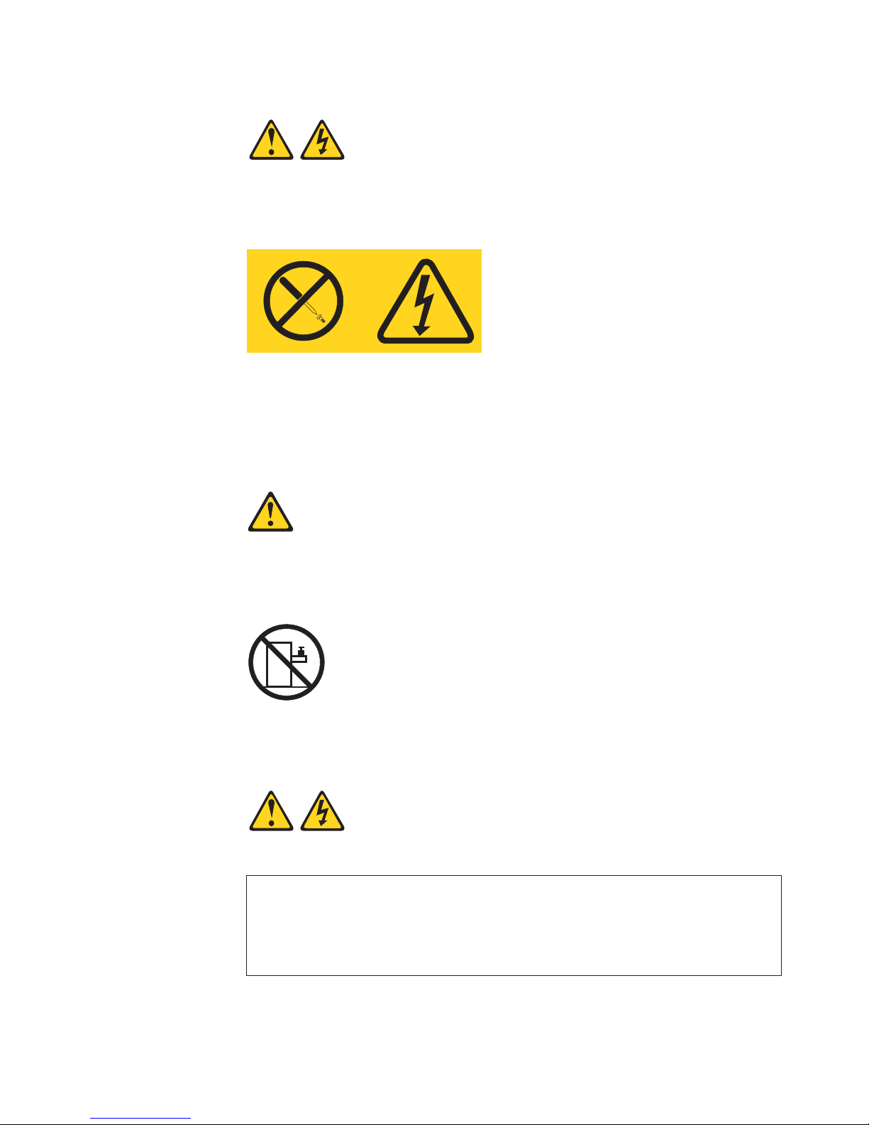
Statement 8:
CAUTION:
Never remove the cover on a power supply or any part that has the following
label attached.
Hazardous voltage, current, and energy levels are present inside any
component that has this label attached. There are no serviceable parts inside
these components. If you suspect a problem with one of these parts, contact
a service technician.
Statement 10:
CAUTION:
Do not place any object weighing more than 82 kg (180 lb) on top of
rack-mounted devices.
>82 kg (180 lb)
Statement 13:
DANGER
Overloading a branch circuit is potentially a fire hazard and a shock hazard
under certain conditions. To avoid these hazards, ensure that your system
electrical requirements do not exceed branch circuit protection
requirements. Refer to the information that is provided with your device for
electrical specifications.
Safety ix

WARNING: Handling the cord on this product or cords associated with accessories
sold with this product, will expose you to lead, a chemical known to the State of
California to cause cancer, and birth defects or other reproductive harm. Wash
hands after handling.
ADVERTENCIA: El contacto con el cable de este producto o con cables de
accesorios que se venden junto con este producto, pueden exponerle al plomo, un
elemento químico que en el estado de California de los Estados Unidos está
considerado como un causante de cancer y de defectos congénitos, además de
otros riesgos reproductivos. Lávese las manos después de usar el producto.
x User’s Guide

Chapter 1. Introducing the SAMSUNG SmartServer 370
Your SAMSUNG SmartServer 370 server is a 4-U-high 1rack model server for
high-volume network transaction processing. This high-performance server, based
on Enterprise X-Architecture
™
technologies, is ideally suited for networking
environments that require superior microprocessor performance, efficient memory
management, flexibility, and reliable data storage.
The SmartServer 370 comes with a limited warranty. You can obtain up-to-date
information about your SmartServer 370 model and other SAMSUNG server
products at http://www.sec.co.kr/server.
Your SmartServer 370 contains several Enterprise X-Architecture technologies,
that help increase performance and reliability. The Enterprise X-Architecture
technologies provided in your server model include the most recent advancements
in X-Architecture features. For more information see “What your server offers"
on page 5 and “Reliability, availability, and serviceability features” on page 7.
The machine type and serial number are located on the ID label located on the left
side of the bezel just above the hard disk drives. You will need these numbers
when you register your server with SAMSUNG.
1. Racks are marked in vertical increments of 1.75 inches each. Each increment is referred to as a unit, or ″U.″ A 1-U-high device is
1.75 inches tall.
1

Related publications
This User’s Guide provides general information about your server, including
information about features, how to configure the server, and how to get help. In
addition to this User’s Guide, the following documentation comes with your server:
v Installation Guide
This printed publication contains instructions for setting up your server and basic
instructions for installing some options.
v Option Installation Guide
This publication is in PDF on the Documentation CD. It contains
detailed instructions for installing, removing, and connecting optional devices that
your server supports.
v Safety Information
This publication is in PDF on the Documentation CD. It contains
translated caution and danger statements. Each caution and danger statement
that appears in the documentation has a number that you can use to locate the
corresponding statement in your language in the Safety Information book.
v Rack Installation Instructions
This printed publication contains instructions for installing your server in a rack
cabinet.
v Hardware Maintenance Manual and Troubleshooting Guide
This publication is in PDF on the Documentation CD. It contains
information to help you solve problems yourself, and it contains information for
service technicians.
Depending on your server model, additional publications might be included on the
Documentation CD.
Your server might have features that are not described in the documentation that
you received with the server. The documentation might be updated occasionally to
include information about those features, or technical updates might be available to
provide additional information that is not included in your server documentation.
These updates are available from the SAMSUNG Web site. Complete the following
steps to check for updated documentation and technical updates:
1. Go to http://www.sec.co.kr/server.
2. In the Family field, select SmartServer 370.
3. Click Display documents.
2 User’s Guide

Notices and statements used in this book
The caution and danger statements used in this book also appear in the multilingual
Safety Information book provided on the Documentation CD. Each
caution and danger statement is numbered for easy reference to the corresponding
statement in the safety book.
The notice and statement definitions are as follows:
v Note: These notices provide important tips, guidance, or advice.
v Important: These notices provide information or advice that might help you avoid
inconvenient or problem situations.
v Attention: These notices indicate possible damage to programs, devices, or
data. An attention notice is placed just before the instruction or situation in which
damage could occur.
v Caution: These statements indicate situations that can be potentially hazardous
to you. A caution statement is placed just before the description of a potentially
hazardous procedure step or situation.
v Danger: These statements indicate situations that can be potentially lethal or
extremely hazardous to you. A danger statement is placed just before the
description of a potentially lethal or extremely hazardous procedure step or
situation.
Chapter 1. Introducing the SmartServer 370 3

Features and specifications
The following information is a summary of the features and specifications of your
server.
Microprocessor:
v Supports the following microprocessors:
– Up to 8 Intel Xeon MP microprocessors (16
in a 16-way configuration)
– Up to 4 Intel Xeon DP microprocessors
Note: Use the Information in BIOS to
determine the type and speed of the
microprocessors installed in your server.
v IBM XA-32
™
chip set with integrated memory,
I/O, system cache, and remote I/O controllers
Memory:
v Minimum: 2 GB
v Maximum: 64 GB
v Type: 2-way interleaved PC1600, DDR
SDRAM, registered DIMMs only
v Supports 512 MB, 1GB and 2 GB dual inline
memory modules (DIMMs)
v XceL4
™
Server Accelerator Cache (up to 64
MB per SMP Expansion Module)
Drives:
v Diskette: 1.44 MB
v DVD-ROM
v Supports up to two internal Ultra320 SCSI
hard disk drives
Active
™
PCI-X expansion slots:
Six 64-bit Active PCI-X expansion slots:
v Two 66 MHz PCI-X slots
v Two 100 MHZ PCI-X slots
v Two 133 MHZ PCI-X slots
v Additional PCI-X slots available in an optional
remote I/O expansion enclosure
Cooling:
Four hot-swap fans:
v Two 150 mm x 51 mm redundant fans
v Two 150 mm x 38 mm fans
Power supply:
Two hot-swap power supplies (550 watts at 110
V ac or 1050 watts at 220 V ac)
Video:
v ATI Rage XL video on system board
v PCI bus interface
v Compatible with SVGA
v 8 MB SDRAM video memory at 125 MHz
Size (4 U):
v Height: 17.8 cm (7 inches, 4 U)
v Depth: 69.85 cm (27.5 inches)
v Width: 48.3 cm (19 inches)
v Maximum weight: 50 kg (110 lb) depending
on your configuration
Integrated functions:
v Broadcom 5704 Dual Gigabit 10/100/1000
Ethernet controller
v Light Path Diagnostics
™
feature
v LSI Logic 1030 Dual Ultra320 SCSI
controller
v Remote Supervisor Adapter (service
processor)
– ASM interconnect (peer-to-peer) port
– Ethernet port
– Management port
v IDE controller
v RXE Management Port
v Three USB connectors
v Keyboard connector
v SCSI connector
v Mouse connector
v Symmetrical multiprocessing (SMP)
Expansion Ports (up to six ports depending
on your configuration)
v Two remote I/O expansion enclosure (RXE)
Expansion Ports
Acoustical noise emissions:
v Sound power, idling: 6.5 bel maximum
v Sound power, operating: 6.5 bel maximum
Environment:
v Air temperature:
– Server on: 10° to 35°C (50.0° to 95.0°F).
Altitude: 0 to 914 m (2998.7 ft).
– Server on: 10° to 32° C (50.0° to 89.6° F).
Altitude: 914 m (2998.7 ft) to 2133 m
(6998.0 ft).
– Server off: -40° to 60° C
(-104° to 140° F). Maximum altitude: 2133 m
(6998.0 ft).
v Humidity:
– Server on: 8% to 80%
– Server off: 5% to 100%
Heat output:
Approximate heat output in British thermal units
(Btu) per hour:
v Minimum configuration: 855 Btu (250 watts)
v Maximum configuration: 2726 Btu (800 watts)
Electrical input:
v Sine-wave input (50 or 60 Hz) required
v Input voltage low range:
– Minimum: 100 V ac
– Maximum: 127 V ac
v Input voltage high range:
– Minimum: 200 V ac
– Maximum: 240 V ac
v Input kilovolt-amperes (kVA) approximately:
– Minimum: 0.250 kVA
– Maximum: 0.800 kVA
Notes:
1. Power consumption and heat output vary
depending on the number and type of optional
features installed and the power-management
optional features in use.
2. These levels were measured in controlled
acoustical environments according to the
procedures specified by the American National
Standards Institute (ANSI) S12.10 and ISO
7779 and are reported in accordance with ISO
9296. Actual sound-pressure levels in a given
location might exceed the average values
stated because of room reflections and other
nearby noise sources. The declared
sound-power levels indicate an upper limit,
below which a large number of computers will
operate.
4 User’s Guide

What your server offers
Your server uses the following features and technologies:
v Accelerated Graphics Port (AGP) adapter
Your server comes with an integrated AGP graphics adapter. This
high-performance adapter supports high resolutions and includes many
performance-enhancing features for your operating-system environment.
v IBM Director
IBM Director is a workgroup-hardware-management tool that you can use
to centrally manage SmartServer.. For more information about IBM Director,
see the IBM Director User’s Guide on the IBM Director CD.
v Enterprise X-Architecture technology
X-Architecture technology combines proven, innovative IBM designs to
make your Intel-processor-based server powerful, scalable, and reliable.
For more information, go to http://www.sec.co.kr/server.
– Active
™
Memory
The Active Memory feature improves the reliability of memory through memory
mirroring, memory scrubbing, and the Memory ProteXion
™
feature. For more
information, see “Active Memory” on page 8.
– Large system-memory capacity
The memory bus supports up to 64 GB of system memory. The memory
controller supports error correcting code (ECC) for up to 32 industry-standard
PC1600, 133 megahertz (MHz), 3.3 V, 168-pin, registered, double-data-rate
(DDR), synchronous dynamic random access memory (SDRAM) dual inline
memory modules (DIMMs).
– Memory ProteXion
The Memory ProteXion feature provides the equivalent of a hot-spare drive in
a RAID array. It is based in the memory controller, and it enables the server to
sense when a chip on a DIMM has failed and to route the data around the
failed chip.
– XceL4
™
Server Accelerator Cache
The XceL4 Server Accelerator Cache provides up to 64MB of external Level-4
cache per SMP Expansion Module, which increases memory bandwidth and
reduces access time through PCI-X, Ethernet, SCSI, and Fibre Channel
interfaces.
v ServerGuide
™
Setup and Installation CD
The ServerGuide Setup and Installation CD that comes with your server provides
programs to help you set up your server and install the operating system. The
ServerGuide program detects installed hardware options and provides the correct
configuration programs and device drivers. For more information about the
ServerGuide Setup and Installation CD, see “Using the ServerGuide Setup and
Installation CD” on page 25.
Note: If your server model came with an operating system, such as Microsoft
®
Windows®2000 Datacenter Server or VMware ESX server, see the
software documentation provided with your software for configuration
information.
Chapter 1. Introducing the SmartServer 370 5

v Integrated network support
Your server comes with an integrated Broadcom 5704 Dual Gigabit Ethernet
controller, which supports connection to a 10-Mbps, 100-Mbps, or 1000-Mbps
network. For more information, see “Configuring the Gigabit Ethernet controller”
on page 29.
v Large data-storage capacity and hot-swap capability
Your server supports up to two 25.4-mm (1-inch) slim-high, 3.5-inch hot-swap
hard disk drives in the hot-swap bays. With the hot-swap feature, you can add,
remove, or replace hard disk drives without turning off the server.
v Light Path Diagnostics feature
The Light Path Diagnostics feature provides LEDs to help you diagnose
problems. For more information, see the section about the Light Path Diagnostics
feature in the Installation Guide.
v Redundant connection
The intergrated dual Giagabit Ethernet ports provide a failover capability. If a
problem occurs with the primary Ethernet connection, all Ethernet traffic
associated with the primary connection is automatically switched to the
secondary connection. If the appropriate device drivers are installed, this
switching occurs without data loss and without user intervention.
v Redundant cooling and power capabilities
The redundant cooling of the fans in your server enable continued operation if
one of the fans fails. Your server comes with two 550-watt hot-swap power
supplies, which provide redundant power for many server configurations. If the
average load on your server is less than 550 watts and a problem occurs with
one of the power supplies, the other power supply can meet the power
requirements.
v Scalable partitions
Your server is scalable and can be connected to another server so that you can
share resources between servers.
v ServeRAID
™
support
Your server supports ServeRAID adapters to create redundant array of
independent disks (RAID) configurations.
v Symmetric multiprocessing (SMP)
Your server supports up to eight Intel Xeon microprocessors (sixteen in a 16-way
configuration). The server comes with two microprocessor. You can install
additional microprocessors to enhance performance.
v Systems-management capabilities
The server comes with a Remote Supervisor Adapter installed. The adapter and
the systems-management software that comes with your server enable you to
manage the functions of the server locally and remotely. The Remote Supervisor
Adapter also provides system monitoring, event recording, and dial-out alert
capability.
6 User’s Guide

Reliability, availability, and serviceability features
Three important computer design features are reliability, availability, and
serviceability (RAS). The RAS features help to ensure the integrity of the data that
is stored in your server, the availability of the computer when you need it, and the
ease with which you can diagnose and repair problems.
Your server has the following RAS features:
v Active Memory
v Active PCI-X (hot-plug) adapter slots
v Advanced Configuration and Power Interface (ACPI)
v Advanced Desktop Management Interface (DMI) features
v Advanced memory ECC, including Memory ProteXion, and multiple Chipkill
™
capability
v Automatic error retry or recovery
v Auto-restart initial program load (IPL) power supply
v Automatic server restart
v Built-in, menu-driven Configuration/Setup Utility and diagnostic programs
v Built-in monitoring for fan, power, temperature, voltage, and power-supply
redundancy
v Customer-upgradable basic input/output system (BIOS) code
v Diagnostic support of Ethernet controllers
v Error codes and messages
v Error correcting code (ECC) protection on the L3 and XceL4 cache
v Failover Ethernet support
v Front-side buses (FSBs) parity protected
v Hot-add memory
v Hot-replace memory
v Hot-swap cooling with fan speed-sensing capability
v Hot-swap hard disk drives
v Light Path Diagnostics
v Memory mirroring
v Microsoft Windows Server family failover support
v Monitoring support for temperature, voltage, and fan speed
v Parity checking on the SCSI buses
v Power-on self-test (POST)
v Processor serial number access
v Read-only memory (ROM) checksums
v Redundant hot-swap
– Cooling fans with speed-sensing capability
– Power supplies
v Remote Supervisor Adapter to enable remote server management
v SDRAM with serial presence detect (SPD) and vital product data (VPD)
v Standard cable presence detection
v Standby voltage for systems-management features and monitoring
v System error logging
v Vital product data (VPD) (includes information stored in nonvolatile memory for
easier remote viewing)
v Wake on LAN
®
capability
Chapter 1. Introducing the SmartServer 370 7

Active Memory
Active™ Memory is an feature that improves the reliability of memory through
memory mirroring, memory scrubbing, and the Memory ProteXion™ feature.
Memory scrubbing and Memory ProteXion
Memory scrubbing tests the memory at regular intervals to detect and report
potential memory errors before they can cause server outages.
If a detected error is recoverable, the Memory ProteXion feature corrects the error
and rewrites the data to another memory location on the same DIMM. The error is
logged in the error log so that you can determine whether preventive maintenance
is necessary.
If there are not sufficient undamaged memory locations that the data can be
rewritten to, the error is unrecoverable. Other conditions can also cause
unrecoverable errors. If a detected error is unrecoverable, LEDs on the Light Path
Diagnostics panel are lit to indicate the failing DIMM.
You do not have to enable memory mirroring to use memory scrubbing and the
Memory ProteXion feature.
Memory mirroring
Memory mirroring stores data in memory port 1 and memory port 2 simultaneously.
To support memory mirroring, you must install identical dual inline memory modules
(DIMMs) in memory port 1 and memory port 2. For more information, see the
section about installing memory modules in the Option Installation Guide on the
Documentation CD.
To enable memory mirroring through the Configuration/Setup Utility program, select
Advanced Setup from the main menu, and select Memory Settings. For more
information about using the Configuration/Setup Utility program, see Chapter 2,
“Configuring the server”, on page 17.
Note: To use the hot-add memory feature memory mirroring must be disabled in
the BIOS code.
IBM Director
With IBM Director, a network administrator can:
v View the hardware configuration of remote systems, in detail
v Monitor the usage and performance of critical components, such as
microprocessors, disks, and memory
v Centrally manage individual or large groups of SAMSUNG and non-SAMSUNG
Intel-based servers, desktop computers, workstations, and mobile computers on
a variety of platforms
IBM Director provides a comprehensive entry-level workgroup hardware manager.
Key features include:
v Advanced self-management capabilities for maximum system availability
v Multiple operating-system platform support, including Windows 2000, Windows
XP Professional, Novell NetWare, Linux, and Caldera OpenUNIX
8 User’s Guide

v Support for SAMSUNG and non-SAMSUNG servers, desktop computers,
workstations, and mobile computers
v Support for systems-management industry standards
v Integration into leading workgroup and enterprise systems-management
environments
v Ease of use, training, and setup
IBM Director also provides an extensible platform that supports advanced server
tools that are designed to reduce the total cost of managing and supporting
networked systems. By deploying IBM Director, you can achieve reductions in
ownership costs through:
v Reduced downtime
v Increased productivity of IT personnel and users
v Reduced service and support costs
For more information about IBM Director, see the IBM Director CD that comes with
your server, the IBM Director publications on the CD.
Systems Management - IBM Director Package
http://www.sec.co.kr/server
This Web page includes links to software downloads and publications for
the latest release of IBM Director.
The UpdateXpress program
The UpdateXpress program is available for most SmartServer and server options.
It detects supported and installed device drivers and firmware in your server and
installs available updates. You can download the UpdateXpress program from
the Web at no additional cost, or you can purchase it on a CD. To download
the program or purchase the CD, go to http://www.sec.co.kr/server/.
Chapter 1. Introducing the SmartServer 370 9
Server controls, LEDs, and power
The following section identifies the controls and indicators on the front and rear of
your server.
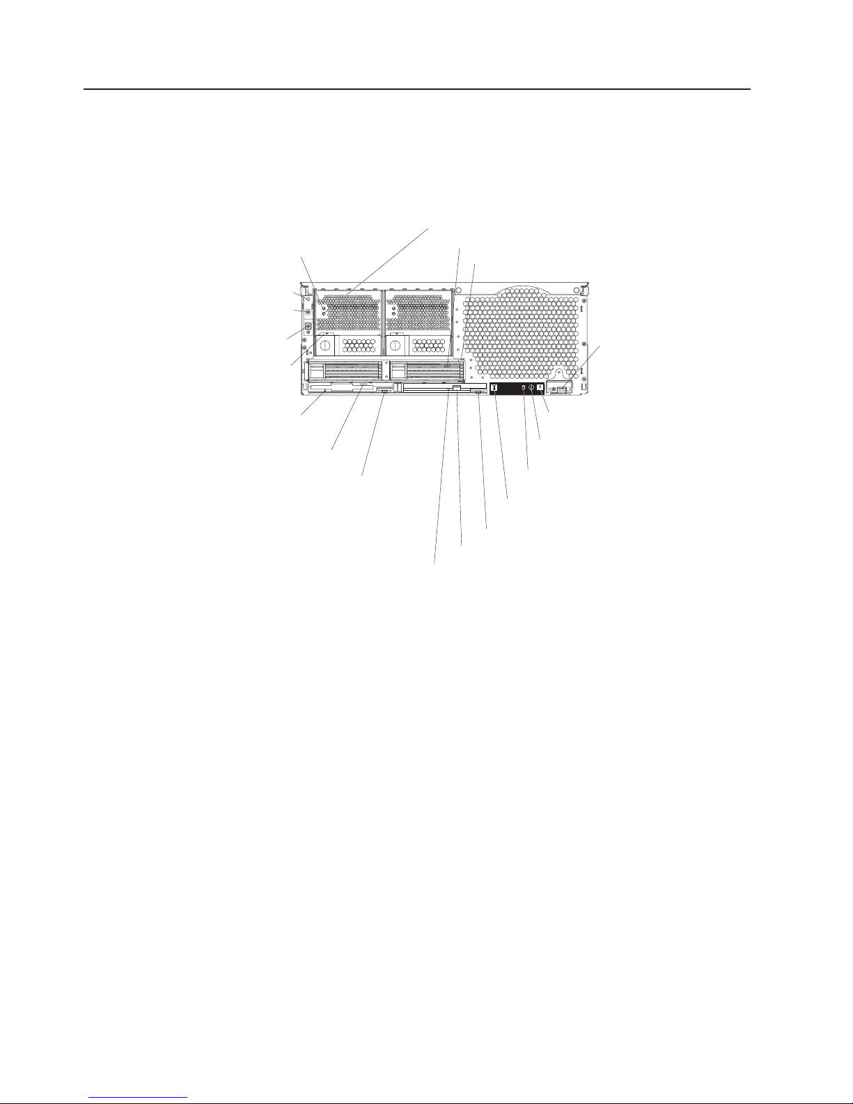
Front view
AC and DC power LED: Each hot-swap power supply has an ac power LED and a
dc power LED. During typical operation, both the ac and dc power LEDs are lit. For
any other combination of LEDs, see the Hardware Maintenance Manual and
Troubleshooting Guide on the Documentation CD.
Hard disk drive activity LED: When this green LED is on, it indicates that the hard
disk drive is in use.
Hard disk drive status LED: When the drive is connected to the integrated SCSI
controller with RAID capabilities, a flashing status LED indicates that the drive is a
secondary drive in a mirrored pair and the drive is being synchronized. When the
drive is connected to an optional ServeRAID controller, a slowly flashing (one flash
per second) status LED indicates that the drive is being rebuilt. When the LED is
flashing rapidly (three flashes per second), it indicates that the controller is
identifying the drive.
USB port: This is an automatically configured port that you can use to connect one
or more USB devices to the front of the server, using Plug and Play technology.
System-error LED: When this amber LED is on, it indicates a system error has
occurred.
Information LED: When this amber LED is on, it indicates information about a
system error has been placed in the System Error log.
Power-control
button
Reset button
Power-on LED
Hard disk drive activity LED
Hard disk drive status LED
USB port
System-error LED
(amber)
Information LED
(amber)
SCSI activity LED
(green)
Locator LED
(blue)
DVD-ROM drive eject button
DVD eject button
DVD-ROM drive activity LED
Power supply
latch
Diskette drive
activity LED
Diskette eject
button
Diskette drive
eject button
AC power LED
DC power LED
Figure 1. Front view of SmartServer 370
10 User’s Guide

SCSI activity LED: When this green LED is on, it indicates that there is activity on
the SCSI bus.
Locator LED: The locator LED is on the left front of the Light Path Diagnostic
drawer. This blue LED indicates the primary and secondary servers. This LED
blinks on the primary server. If the LED remains solid, it indicates that server is the
secondary server.
DVD-ROM drive eject button: Press this button to release a DVD-ROM drive from
the server.
DVD eject button: Press this button to release a DVD from the DVD-ROM drive.
DVD-ROM drive activity LED: When this LED is on, it indicates that the DVD-ROM
drive is in use.
Diskette drive eject button: Press this button to release a diskette drive from the
server.
Diskette eject button: Press this button to release a diskette from the diskette
drive.
Diskette drive activity LED: When this LED is on, it indicates that the diskette
drive is in use.
Power-supply latch: This latch is used to secure the power supply in place.
Reset button: Press this button to reset the server and run the power-on self-test
(POST). You might have to use a pen or the end of a straightened paper clip to
press the button.
Power-control button: Press this button to turn the server on and off manually. A
power-control-button shield comes with your server. You can install this disk-shaped
shield to prevent the server from being turned off accidentally.
Power-control button: Press this button to turn the server on and off manually. A
power-control-button shield comes with your server. You can install this disk-shaped
shield to prevent the server from being turned off accidentally.
Chapter 1. Introducing the SmartServer 370 11
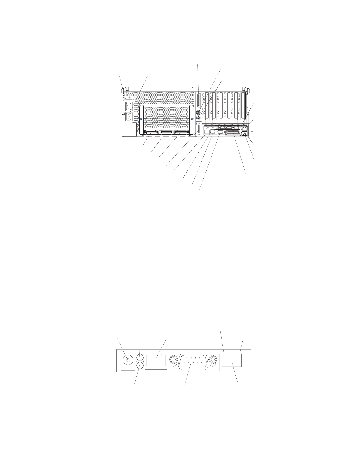
Rear view
System power connectors (1 and 2): The system power cords are connected to
these two connectors to provide power to the system.
RXE Expansion Port B: Use this port to connect the server to a remote I/O
enclosure when two SMP Expansion Modules are installed.
Mouse connector: Connect a mouse or other PS/2
®
device to this connector.
Keyboard port: Signal cables for a keyboard are connected to the keyboard port.
Remote Supervisor Adapter connectors and LEDs: This group of connectors
and LEDs located on the back of the server are used for system management
information and control.
v External power connector - This connector is not supported on this server.
System power
connector 1
System power
connector 2
RXE Expansion Port B
Keyboard connector
Mouse connector
Remote
Supervisor
Adapter
connectors
and LEDs
Upper Ethernet
status LED
Lower Ethernet
status LED
Gigabit Ethernet
connector
Gigabit Ethernet
connector
RXE Expansion
Port (A)
Video connector
USB 2
USB 1
RXE Management Port
SMP Expansion Port 1
SMP Expansion Port 2
SMP Expansion Port 3
SCSI connector
Figure 2. Rear view of SmartServer 370
External power
connector
Error LED
(amber)
Power LED
(green)
ASM interconnect
port
Ethernet link LED
(green)
Ethernet activity LED
(green)
10/100
Ethernet port
Management port
Figure 3. Remote Supervisor Adapter
12 User’s Guide

v Error LED - This amber LED goes on when a system management error has
occurred.
v ASM interconnect port - Signal cables for managing expansion module
resources are connected to this port.
v Ethernet activity LED: When the LED is green there is activity on the Ethernet
LAN.
v Ethernet link LED: When the LED is green the link is active.
v 10/100 Ethernet port - Ethernet Signal cables are connected to the Ethernet
port.
v Management port - Signal cables for modems or other serial devices are
connected to this port.
v Power LED - This green LED is lit when you plug in your server.
Gigabit Ethernet port: Gigabit Ethernet Signal cables are connected to the Gigabit
Ethernet port. This port supports 10/100/1000 speed connections.
Upper Ethernet status LED: This LED, displays the link and activity status for the
upper Gigabit Ethernet port. When the LED is green the link is active. When the
LED blinks green and amber there is activity on the Ethernet LAN.
Lower Ethernet status LED: This LED, displays the link and activity status for the
lower Gigabit Ethernet port. When the LED is green the link is active. When the
LED blinks green and amber there is activity on the Ethernet LAN.
RXE Expansion Port A: Use this port to connect the server to a remote I/O
enclosure, when only one SMP Expansion Module is installed.
Video port: The signal cable for a monitor connects to the video port.
USB 2: This is an automatically configured port that you can use to connect one or
more USB devices to the server, using Plug and Play technology.
USB 1: This is an automatically configured port that you can use to connect one or
more USB devices to the server, using Plug and Play technology.
RXE Management Port: Use this port to connect a management cable from the
server to a remote I/O enclosure.
SCSI port: This port is used to connect external SCSI devices to the server.
SMP Expansion port 3: This port is used to interconnect two SMP Expansion
Modules together in 16-way configurations.
SMP Expansion port 2: This port is used to interconnect two SMP Expansion
Modules together.
SMP Expansion port 1: This port is used to interconnect two SMP Expansion
Modules together.
Chapter 1. Introducing the SmartServer 370 13

Server power features
When the server is connected to an ac power source but is not turned on, the
operating system does not run, and all core logic except for the service processor is
shut down; however, the server can respond to requests from the service processor,
such as a remote request to turn on the server. The power-on LED flashes to
indicate that the server is connected to ac power but not turned on.
Turning on the server
Approximately 20 seconds after the server is connected to ac power, the
power-control button becomes active, and you can turn on the server and start the
operating system by pressing the power-control button.
v The server can also be turned on in any of the following ways:
– If a power failure occurs while the server is turned on, the server will restart
automatically when power is restored.
– If the server is connected to an Advanced System Management interconnect
network that contains at least one server with an optional Remote Supervisor
Adapter installed, the server can be turned on from the Remote Supervisor
Adapter user interface.
– If your operating system supports the system-management software for an
optional Remote Supervisor Adapter, the system-management software can
turn on the server.
– If your operating system supports the Wake on LAN feature, the Wake on
LAN feature can turn on the server.
v If the server is turned on and a power failure occurs, the server will restart
automatically when power is restored.
v If the server is connected to a power source but not turned on, the server can be
turned on from the Remote Supervisor Adapter user interface.
v When you connect your server to power for the first time, the Wake on LAN
feature can turn on the server.
Note: In a 16-way configuration, when you press the power-control button on
either the primary or secondary server, both servers will be turned on. If
both servers do not turn on when either power-control button is pressed,
see the Hardware Maintenance Manual and Troubleshooting Guide on the
Documentation CD.
14 User’s Guide

Turning off the server
When you turn off the server and leave it connected to ac power, the server can
respond to requests from the service processor, such as a remote request to turn
on the server. To remove all power from the server, you must disconnect it from the
power source.
Some operating systems require an orderly shutdown before you turn off the server.
See your operating-system documentation for information about shutting down the
operating system.
Statement 5:
CAUTION:
The power control button on the device and the power switch on the power
supply do not turn off the electrical current supplied to the device. The device
also might have more than one power cord. To remove all electrical current
from the device, ensure that all power cords are disconnected from the power
source.
1
2
The server can be turned off in any of the following ways:
v You can turn off the server from the operating system, if your operating system
supports this feature. After an orderly shutdown of the operating system, the
server will be turned off automatically.
v You can press the power-control button to start an orderly shutdown of the
operating system and turn off the server, if your operating system supports this
feature.
v If the operating system stops functioning, you can press and hold the
power-control button for more than 4 seconds to turn off the server.
v If the server is connected to an Advanced System Management interconnect
network that contains at least one server with an optional Remote Supervisor
Adapter installed, the server can be turned off from the Remote Supervisor
Adapter user interface.
v If an optional Remote Supervisor Adapter is installed in the server, the server can
be turned off from the Remote Supervisor Adapter user interface.
v If the Wake on LAN feature turned on the server, the Wake on LAN feature can
turn off the server.
v The service processor can turn off the server as an automatic response to a
critical system failure.
v You can turn off the server through a request from the service processor.
Note: In a 16-way configuration, when you press the power-control button on either
the primary or secondary server, both servers will be turned off. If both
Chapter 1. Introducing the S martServer 370 15

servers do not turn off when either power-control button is pressed, see the
Hardware Maintenance Manual and Troubleshooting Guide on the Documentation
CD.
16 User’s Guide

Chapter 2. Configuring the server
The following configuration programs and capabilities come with your server:
v Configuration/Setup Utility program
The Configuration/Setup Utility program is part of the basic input/output system
(BIOS) code in your server. Use it to configure management port assignments,
change interrupt request (IRQ) settings, change the startup-device sequence, set
the date and time, and set passwords. For information about using this utility
program, see “Using the Configuration/Setup Utility program” on page 18.
Note: In a 16-way configuration some options or settings are defined through the
primary server, while others must be defined on the individual server.
Ensure that options or settings on the secondary server are correct before
creating a scalable partition.
v ServerGuide Setup and Installation CD
The ServerGuide program provides software-setup tools and installation tools
that are designed for your server. Use this CD during the installation of your
server to configure basic hardware features, such as an integrated SCSI
controller with RAID capabilities, and to simply the installation of your operating
system. For information about using this CD, see “Using the ServerGuide Setup
and Installation CD” on page 25.
Note: If your server model comes with an operating system, such as Microsoft
Windows 2000 Datacenter Server or VMware ESX server, see the
software documentation provided with your software for configuration
information.
v Ethernet controller configuration
For information about configuring the Ethernet controller, see “Configuring the
Gigabit Ethernet controller” on page 29.
v Extensible Firmware Interface (EFI) boot manager
The EFI boot manager provides a choice of startup options when you start the
server. Use it to start the operating system, the Configuration/Setup Utility
program, the LSI Logic Configuration Utility program, and the EFI boot manager
maintenance menu. For information about using this program, see “Using the
Extensible Firmware Interface boot manager” on page 29.
v Integrated system management firmware update utility program
For information about updating the integrated system management firmware, see
“Using the integrated system management firmware update utility program” on
page 30.
v LSI Logic Configuration Utility program
Use the LSI Logic Configuration Utility to configure the integrated SCSI controller
with RAID capabilities and the devices that are attached to it. For information
about using this utility program, see “Using the LSI Logic Configuration Utility
program” on page 31.
v Remote Supervisor Adapter configuration process
Configuration activities are also required for the Remote Supervisor Adapter. See
“Setting up the Remote Supervisor Adapter” on page 32 for information about
setting up and cabling the Remote Supervisor Adapter for use with an Advanced
System Management (ASM) network.
v Preboot Execution Environment (PXE) boot agent utility program
17

The PXE boot agent utility program is part of the BIOS code in your server. Use
it to change network startup (boot) protocols and startup order and to select
operating-system wake-up support. For information about using this utility
program, see “Using the PXE boot agent utility program” on page 50.
v ServeRAID Manager
ServeRAID Manager is available as a stand-alone program and as an IBM Director
extension. If a ServeRAID adapter is installed in your server or if you are
using the RAID capabilities of the integrated SCSI controller, use ServeRAID
Manager to define and configure your disk-array subsystem before you install the
operating system. For information about using this program, see “Using
ServeRAID Manager” on page 51.
v Configuring Scalable Partitions
To create or remove scalable partitions, see “Configuring scalable partitions” on
page 58.
Usingthe Configuration/Setup Utility program
The Configuration/Setup Utility program is part of the BIOS code. You can use it to:
v Configure system devices and ports
v Configure scalable partitions
v Change the drive startup sequence
v Enable USB keyboard and mouse support
v Resolve configuration conflicts
v Set the date and time
v Set passwords and security settings
Starting the Configuration/Setup Utility program
Complete the following steps to start the Configuration/Setup Utility program:
1. Turn on the server.
Note: In a 16-way configuration some options or settings are defined through
the primary server, while others must be defined on the individual server.
Ensure that options or settings on the secondary server are correct
before creating a scalable partition.
2. When the prompt Press F1 for Configuration/Setup appears, press F1. If you
have set both a power-on password and an administrator password, you must
type the administrator password to access the full Configuration/Setup Utility
menu. If you do not type the administrator password, a limited
Configuration/Setup Utility menu is available.
Note: Depending on your configuration you might experience a delay before
the Configuration/Setup menu appears.
3. Select settings to view or change.
Configuration/Setup Utility menu choices
The following choices are on the Configuration/Setup Utility main menu. Depending
on the version of the BIOS code in your server, some menu choices might differ
slightly from these descriptions.
v System Summary
Select this choice to view configuration information, including the type, speed,
and cache sizes of the microprocessors and the amount of installed memory.
18 User’s Guide

When you make configuration changes through other options in the
Configuration/Setup Utility program, the changes are reflected in the system
summary; you cannot change settings directly in the system summary.
This choice is on the full and limited Configuration/Setup Utility menu.
v System Information
Select this choice to view information about your server. When you make
changes through other options in the Configuration/Setup Utility program, some
of those changes are reflected in the system information; you cannot change
settings directly in the system information.
This choice is on the full Configuration/Setup Utility menu only.
– Product Data
Select this choice to view the machine type and model of your server, the
serial number, and the revision level or issue date of the BIOS and
diagnostics code stored in electrically erasable programmable ROM
(EEPROM).
v Devices and I/O Ports
Select this choice to view or change assignments for devices and input/output
(I/O) ports and to configure the remote console redirection.
Select this choice to enable or disable integrated SCSI and Ethernet controllers
and all standard ports (such as the serial port). Enable is the default setting for
all controllers. If you disable a device, it cannot be configured, and the operating
system will not be able to detect it (this is equivalent to disconnecting the
device). If you disable the integrated SCSI controller and no SCSI adapter is
installed, the server will have no SCSI capability. If you disable the integrated
Ethernet controller and no Ethernet adapter is installed, the server will have no
Ethernet capability.
Select this choice to configure and enable the remote console redirection feature
on the server. This feature allows the user to view POST execution, change
system configuration settings and to use DOS based configuration utilities
remotely. See “Remote console redirection” on page 23 for more information.
This choice is on the full Configuration/Setup Utility menu only.
v Date and Time
Select this choice to set the date and time in the server, in 24-hour format
(hour:minute:second).
This choice is on the full Configuration/Setup Utility menu only.
v System Security
Select this choice to set passwords and the Remote Control Security settings.
See “Passwords” on page 24 for more information about passwords. You can
also enable the chassis-intrusion detector to alert you each time the server cover
is opened.
Note: In a 16-way configuration security settings are defined through the primary
server. If you bypass the 16-way configuration during start up or start the
servers in a stand alone configuration; then, you must define the security
setting on each individual server.
This choice is on the full Configuration/Setup Utility menu only.
– Power-on Password
Select this choice to set or change a power-on password. See “Power-on
password” on page 24 for more information.
– Administrator Password
Chapter 2. Configuring the server 19

Attention: If you set an administrator password and then forget it, there is
no way to change, override, or remove it. You must replace the system board.
This choice is on the Configuration/Setup Utility menu only if an SAMSUNG
Remote Supervisor Adapter is installed.
Select this choice to set or change an administrator password. An
administrator password is intended to be used by a system administrator; it
limits access to the full Configuration/Setup Utility menu. If an administrator
password is set, the full Configuration/Setup Utility menu is available only if
you type the administrator password at the password prompt. See
“Administrator password” on page 25 for more information.
v Start Options
Select this choice to view or change the start options. Changes in the start
options take effect when you restart the server.
You can set keyboard operating characteristics, such as the keyboard speed, and
you can specify whether the server starts with the keyboard number lock on or
off. You can enable the server to run without a diskette drive, monitor, or
keyboard.
The startup sequence specifies the order in which the server checks devices to
find a boot record. The server starts from the first boot record that it finds. If your
server has Wake on LAN hardware and software and the operating system
supports Wake on LAN functions, you can specify a startup sequence for the
Wake on LAN functions. You can also specify whether the integrated SCSI
controller or a PCI SCSI adapter has boot precedence.
If you enable the boot fail count, the BIOS default settings will be restored after
three consecutive failures to find a boot record.
You can enable a virus-detection test that checks for changes in the boot record
when the server starts.
This choice is on the full Configuration/Setup Utility menu only.
v Advanced Setup
Select this choice to change settings for advanced hardware features.
Important: The server might malfunction if these options are incorrectly
configured. Follow the instructions on the screen carefully.
This choice is on the full Configuration/Setup Utility menu only.
– CPU Socket State
You can enable a CPU socket and view the CPU socket state.
– System Partition Visibility
Select this choice to specify whether the System Partition is to be visible or
hidden. See “Using the ServerGuide Setup and Installation CD” on page 25
for information about the System Partition.
– Memory Settings
Select this choice to manually enable a pair of memory connectors. If a
memory error is detected during POST or memory configuration, the server
automatically disables the failing pair of memory connectors and continues
operating with reduced memory. After the problem is corrected, you must
manually enable the memory connectors. Use the arrow keys to highlight the
pair of memory connectors that you want to enable, and use the arrow keys to
select Enable.
The following gives information about memory mirroring:
- The hot-add memory feature allows you to add DIMMs without turning off
the server. This feature is supported only in those servers using Windows
Server 2003 Enterprise or Datacenter editions.
20 User’s Guide

- To use the hot-add memory feature memory mirroring must be Disabled.
- To use the hot-replace memory feature memory mirroring must be Enabled.
– CPU Options
Select this choice to specify whether the serial number in the microprocessor
is to be readable. You can also disable the microprocessor cache or set it to
use the write-back or write-through method. Write-back caching generally
provides better system performance.
– PCI Bus Control
Select this choice to view and set interrupts for PCI devices and to configure
the master-latency-timer value for the server.
– Integrated System Management Processor Settings
Select this choice to enable or disable the Reboot on System NMI option on
the menu. If you enable this option, the server will automatically restart 60
seconds after the service processor issues a nonmaskable interrupt (NMI) to
the server. If you disable this option, the server will not restart. Enable is the
default setting.
– Scalability Port Configuration
Select this choice to view a summary of the current scalability port
configurations.
Note: Scalability ports are called SMP Expansion Ports in this publication.
– Scalable Partition Settings
Select this choice to view a summary of current scalable partition settings and
to configure or delete partition settings.
Notes:
1. Partition settings are called partition descriptors in some IBM
documentation.
2. See “Configuring scalable partitions” on page 58″ for more information on
creating, deleting, and configuring scalable partitions.
v Error Logs
Select this choice to view or clear error logs.
Note: When troubleshooting problems with PCI-X slots, you will notice that the
error logs report the PCI-X busses numerically. The numerical assignment
will change depending on your configuration.
– POST Error Log
Select this choice to view the three most recent error codes and messages
that were generated during POST. Select Clear error logs to clear the POST
error log.
– System Event/Error Log
Select this choice to view the System Event/Error log, which contains all
system error and warning messages that have been generated. Use the arrow
keys to move between pages in the log. Select Clear error logs to clear the
System Event/Error log.
v Save Settings
Select this choice to save the changes you have made in the settings.
v Restore Settings
Select this choice to cancel the changes you have made in the settings and
restore the previous settings.
Chapter 2. Configuring the server 21

v Load Default Settings
Select this choice to cancel the changes you have made in the settings and
restore the factory settings.
v Exit Setup
Select this choice to exit from the Configuration/Setup Utility program. If you have
not saved the changes you have made in the settings, you are asked whether
you want to save the changes or exit without saving them.
Additional Configuration/Setup Utility menu choices
With the IBM Remote Supervisor Adapter in your server, you can view the following
additional menu choices:
v System Card Data
Select this choice to display information about your server.
v PCI Slot/Device Information
Select this choice to view the properties of adapters installed in PCI slots.
v Administrator Password
Select this choice to set or change the administrator password.
v Remote Control Security Settings
Select this choice to set a remote-control password. When you set a
remote-control password, you can also set the number of times the wrong
remote-control password can be entered before the user is locked out of the
server, and the duration before another attempt is allowed.
v RSA I Settings
Select this choice to view the MAC address, IP address, subnet mask address,
and gateway information and to set the DHSP control.
For a list of supported options for your server, go to
http://www.sec.co.kr/server/. To order an option, contact your SAMSUNG marketing
representative or authorized reseller.
22 User’s Guide

Remote console redirection
From the Devices and I/O Ports choice, you can enable and configure the remote
console redirection through the Remote Console Redirection submenu. The
Devices and I/O Ports choice is on the full Configuration/Setup menu only.
Complete the following steps to enable and configure the remote console
redirection feature:
1. Ensure that you have installed and enabled the serial port that comes with your
server. See ″Installing the serial port″ in the Installation Guide.
2. From the Devices and I/O Ports choice, use the Up Arrow and Down Arrow
keys (↑ and ↓) to select Remote Console Redirection; then, press Enter. The
Remote Console Redirection window opens.
3. In the Remote Console Redirection window Enable the remote console
redirection and enter the necessary settings for the server to work with a remote
console.
Note: The remote console settings must match those in the Remote Console
Redirection window to ensure proper operation.
4. Once you have made the necessary changes, press Esc.
5. Select Save Settings; then, press Enter.
6. Confirm your selection; then, exit the Configuration/Setup Utility program.
7. Connect the server to a remote console using a null modem cable.
Chapter 2. Configuring the server 23

Passwords
From the System Security choice, you can set, change, and delete a power-on
password and an administrator password. The System Security choice is on the
full Configuration/Setup menu only.
Note: In a 16-way configuration security settings are defined through the primary
server. If you bypass the 16-way configuration during start up or start the
servers in a stand alone configuration; then, you must define the security
setting on each individual server.
If you set only a power-on password, you must type the power-on password to
complete the system startup, and you have access to the full Configuration/Setup
Utility menu.
An administrator password is intended to be used by a system administrator; it
limits access to the full Configuration/Setup Utility menu. If you set only an
administrator password, you do not have to type a password to complete the
system startup, but you must type the administrator password to access the
Configuration/Setup Utility menu.
If you set a power-on password for a user and an administrator password for a
system administrator, you can type either password to complete the system startup.
A system administrator who types the administrator password has access to the full
Configuration/Setup Utility menu; the system administrator can give the user
authority to set, change, and delete the power-on password. A user who types the
power-on password has access to only the limited Configuration/Setup Utility menu;
the user can set, change, and delete the power-on password, if the system
administrator has given the user that authority.
Power-on password
If a power-on password is set, when you turn on the server, the system startup will
not be completed until you type the power-on password. You can use any
combination of up to seven characters (A–Z, a–z, and 0–9) for the password.
When a power-on password is set, you can enable the Unattended Start mode, in
which the keyboard and mouse remain locked but the operating system can start.
You can unlock the keyboard and mouse by typing the power-on password.
If you forget the power-on password, you can regain access to the server in any of
the following ways:
v If an administrator password is set, type the administrator password at the
password prompt. Start the Configuration/Setup Utility program and reset the
power-on password.
v Remove the server battery and then reinstall it. See the Option Installation Guide
for instructions for removing the battery.
v Change the position of the power-on password override switch (switch 6 on
switch block 1 on the system board) to bypass the power-on password check.
Attention: Before changing any switch settings or moving any jumpers, turn off
the server; then, disconnect all power cords and external cables. See the safety
information beginning on page “Safety” on page v. Do not change settings or
move jumpers on any system-board switch or jumper blocks that are not shown
in this book.
24 User’s Guide

While the server is turned off, move the switch to the position opposite its current
position. You can then start the Configuration/Setup Utility program and reset the
power-on password. You do not need to return the switch to the previous
position.
The power-on password override switch does not affect the administrator
password.
Administrator password
If an administrator password is set, you must type the administrator password for
access to the full Configuration/Setup Utility menu. You can use any combination of
up to seven characters (A–Z, a–z, and 0–9) for the password. The Administrator
password choice is on the Configuration/Setup Utility menu only if an Remote
Supervisor Adapter is installed.
Attention: If you set an administrator password and then forget it, there is no way
to change, override, or remove it. You must replace the system board.
Using the ServerGuide Setup and Installation CD
The ServerGuide Setup and Installation CD includes an easy-to-use setup and
installation program that is designed for your server. The ServerGuide program
detects the server model and hardware options that are installed and uses that
information during setup to configure the hardware. The ServerGuide program
simplifies operating-system installations by providing updated device drivers and, in
some cases, installing them automatically.
Note: If your server model came with an operating system, such as Microsoft
Windows 2000 Datacenter Server or VMware ESX server, see the software
documentation provided with your software for configuration information.
If a later version of the ServerGuide program is available, you can download a free
image of the ServerGuide Setup and Installation CD, or you can purchase the CD.
To download the image, go to the ServerGuide Web page at
http://www.sec.co.kr/server/.
To purchase the latest ServerGuide Setup and Installation CD, go to the ServerGuide
fulfillment Web site at http://www.sec.co.kr/server/.
The ServerGuide program has the following features to make setup easier:
v An easy-to-use interface with online help
v Diskette-free setup, and configuration programs that are based on detected
hardware
v ServeRAID Manager program, which configures your ServeRAID adapter or
integrated SCSI controller with RAID capabilities
v A system BIOS code update program, which updates the BIOS code directly from
the CD
v Device drivers that are provided for your server model and detected hardware
v Operating-system partition size and file-system type that are selectable during
setup
ServerGuide features
Features and functions can vary slightly with different versions of the ServerGuide
program. To learn more about the version that you have, start the ServerGuide
Setup and Installation CD and view the online overview. Not all features are
supported on all server models.
Chapter 2. Configuring the server 25

The ServerGuide program requires a supported SAMSUNG server with an enabled
startable (bootable) CD-ROM or DVD-ROM drive. In addition to the ServerGuide
Setup and Installation CD, you must have your operating-system CD to install your
operating system.
The ServerGuide program has the following features:
v Sets system date and time.
v Detects the SCSI RAID adapter, controller, or integrated SCSI controller with
RAID capabilities and runs the SCSI RAID configuration program.
v Updates the licensed internal code (firmware) level without diskettes.
v Checks the system BIOS code and microcode (firmware) levels of supported
options to determine whether a later level is available from the CD. You can
perform updates without using diskettes.
v Creates a System Partition on the default drive. You can run server-specific utility
programs after setup.
v Detects installed hardware options and provides updated device drivers for most
adapters and devices.
v Creates a setup-replication diskette for replicating setup selections for other
servers of the same model.
v Provides diskette-free installation for supported operating systems.
v Provides a replicated installation path for multiple installations of supported
operating systems.
v Includes an online readme file with links to tips for your hardware and
operating-system installation.
Setup and configuration overview
When you use the ServerGuide Setup and Installation CD, you do not need setup
diskettes. You can use the CD to configure any supported SAMSUNG server model.
The ServerGuide program checks your system BIOS, service processors, and other
system hardware to determine if system updates are available. The setup program
provides a list of tasks that are required to set up your server model. On a server
with a ServeRAID adapter or integrated SCSI controller with RAID capabilities, you
can run the SCSI RAID configuration program to create logical drives.
Note: Features and functions can vary slightly with different versions of the
ServerGuide program.
When you start the ServerGuide Setup and Installation CD, the program performs
the following tasks:
v The ServerGuide program prompts you for your language, country, and keyboard
layout. (This information is stored and later passed to the operating-system
installation program.)
v The ServerGuide program displays choices for running the configuration
programs. For example:
– The Express Configuration method runs the required programs for your
server, based on the hardware that is detected.
– The Custom Configuration method displays all programs that are available for
your server, and you decide which programs to run.
– The Replicated Configuration method provides the option of duplicating your
setup selections to other servers that are the same model.
v If you select the Custom Configuration method, the following features are
optional. If you select the Express Configuration method, some or all of these
features are run, depending on the hardware that is detected:
26 User’s Guide

– The Set Date and Time feature is provided so that you do not have to use the
Configuration/Setup Utility program to access these settings.
– The Clear Hard Disks feature is provided so you can delete all partitions on all
hard disk drives.
– The ServerGuide program checks the server BIOS code and microcode
(firmware) levels for supported options and then checks the CD for a newer
level. The CD content might be newer than the BIOS code and firmware level.
The ServerGuide program can perform a flash update of the BIOS code and
supported microcode (firmware) options without using diskettes.
– The SCSI RAID configuration program starts, leading you through the entire
configuration process.
– The ServerGuide program creates a System Partition on the default drive.
v The ServerGuide program displays a confirmation summary, so that you will
know when you have completed all the required tasks. Then, you are ready to
install your operating system.
Notes:
1. Plug and Play adapters are configured automatically. Non-Plug and Play
adapters or non-IBM adapters might require switch settings, additional device
drivers, and installation after the operating system is installed. See the
documentation that comes with the adapter.
2. Diagnostics for your server come in the BIOS code.
System Partition
The ServerGuide program creates a 50 MB System Partition on the default drive.
The System Partition contains server-specific utility programs such as
service-processor disk operating system (DOS) utilities, system diagnostics, flash
BIOS updates, and other programs. Programs in the System Partition vary by
server model, and not all server models run utility programs from the System
Partition. To determine which ones do, start the ServerGuide Setup and Installation
CD and view the online overview.
After setup is complete, you can access programs in the System Partition by
restarting the server and pressing Alt+F1 when the prompt is displayed. The
System Partition menu displays the programs that are available on your server
model.
Typical operating-system installation
You can use the ServerGuide program to shorten your installation time. The
ServerGuide program provides the device drivers that are required for your
hardware and for the operating system that you are installing. This section
describes a typical ServerGuide operating-system installation.
Note: Features and functions can vary slightly with different versions of the
ServerGuide program.
1. After you have completed the setup process, the operating-system installation
program starts. (You will need your operating-system CD to complete the
installation.)
2. The ServerGuide program stores information about the server model, service
processor, hard disk drive controllers, and network adapters. Then, the program
checks the CD for newer device drivers. This information is stored and then
passed to the operating-system installation program.
Chapter 2. Configuring the server 27

3. With some operating-system installations, you can create an operating-system
replication diskette for setting up additional servers. This diskette contains the
Internet protocol (IP) address, server name, and other selections.
4. The ServerGuide program presents operating-system partition options that are
based on your operating-system selection and the installed hard disk drives.
5. If you are installing the operating system from diskettes, the ServerGuide
program lists the diskettes that you must create and the optional device-driver
diskettes (for installed adapters or controllers) that you might want to create.
6. The ServerGuide program prompts you to insert your operating-system CD and
restart the server. At this point, the installation program for the operating system
takes control to complete the installation.
The following table contains information about the operating systems supported by
the server:
Table 1. Supported operating systems and the configurations they support
Operating system
ServerGuide
support
Maximum
memory and SMP
support
Hot-plug
PCI
support
Memory
hot-add
support
Hyperthreading
support
Microsoft Windows NT
®
Server 4.0
Enterprise Edition
No 4 GB, Single SMP
Expansion module
only (2-way with
Intel Xeon DP
microprocessors,
4-way with Intel
Xeon MP
microprocessors)
No No No
Microsoft Windows 2000 Server Yes 4 GB, 4-way Yes No No
Microsoft Windows 2000 Advanced Server Yes 8 GB, 8-way Yes No No
Microsoft Windows 2000 Datacenter
Server
No 32 GB, 16-way Yes No Yes
Microsoft Windows Server 2003 Standard
Edition
No 4 GB, 4-way Yes No Yes
Microsoft Windows Server 2003
Enterprise Edition
No 32 GB, 8-way Yes Yes Yes
Microsoft Windows Server 2003
Datacenter Edition
No 64 GB, 16-way Yes Yes Yes
Novell NetWare 6.0 No 64 GB, 8-way Yes No Yes
Red Hat Linux Advanced Server 2.1 No 16 GB, 8-way Yes No Yes
SCO UnixWare 7.1.3 No 64 GB, 8-way No No Yes
SuSE Linux Enterprise Server 8 No 32 GB, 8-way Yes No Yes
VMware ESX Server 2.0 No 64 GB, 16-way No No No
Setting up or updating multiple servers
You can use the ServerGuide program to create diskettes that help you set up or
update multiple servers. You can modify information on the diskettes as you use
them to set up or update other servers.
Note: Availability and function can vary by server model and by the hardware that
is installed.
28 User’s Guide

You can create a setup-replication diskette, which contains your hardware
configuration selections. Use this diskette to replicate selections to other servers
that are of the same model.
You can create an operating-system replication diskette, which contains information
that you need to complete multiple installations. Not all operating systems support
operating-system replication diskettes.
Installing your operating system without ServerGuide
If you have already configured the server hardware and you decide not to use the
ServerGuide program to install your operating system, complete the following steps
to download the latest operating-system installation instructions from the SAMSUNG
Support Web page:
1. Go to http://www.sec.co.kr/server/.
2. In the Download section, click Downloads & drivers.
3. On the ″Downloads and drivers″ page, in the Brand field, select Servers.
4. In the Family field, select SmartServer 370.
5. Click Display documents.
6. In the View by document type field, select OS installation.
7. Select the instructions for your operating system.
Configuring the Gigabit Ethernet controller
The Ethernet controller is integrated on the system board. It provides an interface
for connecting to a 10-Mbps, 100-Mbps, or 1-Gbps network and provides full-duplex
(FDX) capability, which enables simultaneous transmission and reception of data on
the network. If the Ethernet ports in your server support auto-negotiation, the
controller detects the data-transfer rate (10BASE-T, 100BASE-TX, or 1000BASE-T)
and duplex mode (full-duplex or half-duplex) of the network and automatically
operates at that rate and mode.
You do not need to set any jumpers or configure the controller. However, you must
install a device driver to enable the operating system to address the controller. For
device drivers and information about configuring the Ethernet controller, see the
Broadcom NetXtreme Gigabit Ethernet Software CD that comes with your server.
For updated information about configuring the controller, go to
http://www.sec.co.kr/server/.
Using the Extensible Firmware Interface boot manager
Use the Extensible Firmware Interface (EFI) boot manager to configure startup
options. The EFI boot manager main menu is displayed automatically when you
start the server.
The following choices are available from the EFI boot manager maintenance menu:
v Boot from a file
Select this choice to automatically add EFI applications as startup options or to
start the server from a specific file.
v Add a boot option
Select this choice and specify the name of an EFI application to add a startup
option to the EFI boot manager.
v Delete boot options
Chapter 2. Configuring the server 29

Select this choice to delete a specific startup option or all startup options.
v Change boot order
Select this choice to control the relative order in which the EFI boot manager
attempts startup options.
v Manage boot next setting
Select this choice to define a startup option to be used for the next startup
operation only.
v Set automatic boot timeout value
Select this choice to define the amount of time that will elapse before the server
starts automatically without user intervention.
v Select active console output devices
Select this choice to display a list of available console output devices, as defined
in the ConOutDev list, and select an output console device.
v Select active console input devices
Select this choice to display a list of available console input devices, as defined
in the ConInDev list, and select an input console device.
v Select active error devices
Select this choice to display a list of available error devices, as defined in the
ErrOutDev list and the subset described in the ErrOut variable, and select an
error device.
v Cold reset
Select this choice to perform a platform-specific cold reset of the server. (A cold
reset typically is a full-platform reset.)
v Exit
Select this choice to return to the EFI boot manager startup options and display a
list of the active startup devices.
Using the integrated system management firmware update utility
program
To update the integrated system management firmware for the integrated system
management processor (ISMP), download the Integrated System Management
Firmware Update Utility program for your server from the SAMSUNG Web site at
http://www.sec.co.kr/server/. Run the Integrated System Management Firmware
Update Utility program to create a diskette to use to update the firmware. The
diskette updates the firmware only and does not affect any device drivers.
Complete the following steps to update the firmware:
1. Turn off the server.
2. Insert the diskette into the diskette drive.
3. Turn on the server. If the server does not start from the diskette, use the
Configuration/Setup Utility program to configure the diskette drive as a startup
device. (See “Using the Configuration/Setup Utility program” on page 18.) Then,
start again at step 1.
4. From the main menu, select Update System Management Firmware and
press Enter.
5. Follow the instructions on the screen to complete the update.
If there is an error in updating the firmware, try the update again.
30 User’s Guide

Using the LSI Logic Configuration Utility program
Use the LSI Logic Configuration Utility program to:
v Perform a low-level format of a SCSI hard disk drive
v Set a SCSI device scan order
v View or change SCSI IDs for attached devices
v Create a mirrored pair of SCSI hard disk drives with or without a hot-spare drive
v Set SCSI protocol parameters on SCSI hard disk drives
The integrated SCSI controller with RAID capabilities supports redundant array of
independent disks (RAID). You can use the LSI Logic Configuration Utility program
to configure RAID level 1 for a single pair of attached devices. If you install a
different type of RAID adapter, follow the configuration instructions in the
documentation that comes with the adapter to view or change SCSI settings for
attached devices.
The following sections provide instructions for starting the LSI Logic Configuration
Utility program and performing selected functions.
Starting the LSI Logic Configuration Utility program
Complete the following steps to start the LSI Logic Configuration Utility program:
1. Turn on the server.
2. When the prompt <<< Press <CTRL><C> to start LSI Logic Configuration
Utility >>> appears, press Ctrl+C. If you have set an administrator password,
you are prompted to type the password.
3. Use the arrow keys to select a controller (channel) from the list of adapters;
then, press Enter.
4. Follow the instructions on the screen to change the settings of the selected
items; then, press Enter. If you select Device Properties or Mirroring
Properties, additional screens are displayed.
When you have finished changing settings, press Esc to exit from the program;
select Save to save the settings that you have changed.
Formatting a SCSI hard disk drive
Low-level formatting removes all data from the hard disk. If there is data on the disk
that you want to save, back up the hard disk before performing this procedure.
Note: Before you format a SCSI hard disk, make sure that the disk is not part of a
mirrored pair. From the list of adapters, select the controller (channel) for the
drive that you want to format. Select Mirroring Properties and make sure
that the mirroring value for the drive is None.
Complete the following steps to format a drive:
1. From the list of adapters, select the controller (channel) for the drive that you
want to format.
2. Select Device Properties.
3. Use the arrow keys (↑ and ↓) to highlight the drive that you want to format.
4. Use the arrow keys (← and →) or the End key to scroll to the right.
5. Select Format; then, press Enter to start the low-level formatting operation.
Chapter 2. Configuring the server 31

Creating a mirrored pair of SCSI hard disk drives
Complete the following steps to create a mirrored pair of SCSI hard disk drives:
1. From the list of adapters, select the controller (channel) for the drives that you
want to mirror.
2. Select Mirroring Properties.
3. Use the arrow keys to highlight the first drive in the pair; then, press the Minus
key to change the mirroring value to Primary.
4. Use the arrow keys to highlight the second drive in the pair; then, press the
Minus key to change the mirroring value to Secondary.
5. To establish a third drive that will take over the function of either mirrored drive
in the event of a failure, use the arrow keys to highlight the drive that you want
to use for that purpose; then, press the Minus key to change the mirroring value
to Hot Spare.
Setting up the Remote Supervisor Adapter
This section describes the Remote Supervisor Adapter features and prerequisites
for installation. It also explains how to use the documentation effectively and how to
cable and configure the adapter for use on an Advanced System Management
(ASM) network so that you can manage the server from a remote location. For
more detailed information, see the Remote Supervisor Adapter User’s Guide on the
Documentation CD.
Remote Supervisor Adapter features
The Remote Supervisor Adapter has the following features:
v Continuous health monitoring and control
v Advanced Predictive Failure Analysis
®
(PFA)
v Configurable notification and alerts
v Event logs that are timestamped, saved in nonvolatile memory, and can be
attached to e-mail alerts
v Remote graphics console redirection
v LAN, serial, and Advanced System Management (ASM) interconnect remote
access
v Point-to-point protocol (PPP) support
v Simple Network Management Protocol (SNMP)
v Domain Name System (DNS) and Dynamic Host Configuration Protocol (DHCP)
support
v Remote power control
v Microsoft Windows NT and Windows 2000 blue-screen capture
v Remote firmware update and access to critical server settings
v Optional, independent power, which enables around-the-clock access to the
server, even if the server is powered off
Setup requirements
Before you set up the Remote Supervisor Adapter, you must download to a
diskette, the DOS Remote Supervisor Utility program from
http://www.sec.co.kr/server.
Perform the following before you set up the Remote Supervisor Adapter:
32 User’s Guide

v Install the operating system on the server, using ServerGuide and the
documentation that comes with the operating system.
v Install the agent component of UM Server Extensions to use the following
Advanced System Management (ASM) Web interface features:
– Shutdown O/S and then Power Off Server
– Shutdown O/S and then Restart Server
UM Server Extensions is on the system-management software CD that comes
with the server. For information about installing the agent component, see the
documentation that comes with the system-management CD.
v To configure the remote alert recipients for IBM Director over LAN or IBM Director
over modem, the remote alert recipient must be an IBM Director-enabled server
with UM Server Extensions.
v If you want to use a Web browser to access the Remote Supervisor Adapter
remotely, the following software is required:
– Microsoft Internet Explorer 4.0 (with Service Pack 1), or later
– Netscape Navigator 4.72, or later (version 6.0 is not currently supported)
– Java
™
enabled Web browser (See your browser documentation or online Help
for instructions about enabling its Java support.)
– Support for JavaScript
™
1.2, or later (See your browser documentation or
online Help for instructions about enabling its JavaScript support.)
– Support of HTTP version 1.0, or later
– Minimum display resolution of 800 x 600 pixels and 256 colors
Note: The ASM Web interface and the ASM text-based interface do not support
the double-byte character set (DBCS) languages.
Using the documentation
The documentation for the Remote Supervisor Adapter includes the following
publications on the Documentation CD.
v SmartServer 370 User’s Guide (this document, specifically the topics in this
section, which assist you with the cabling and configuring).
v Remote Supervisor Adapter User’s Guide
This document explains how to configure and use an ASM network to manage
the server remotely through either the Web-based interface or the text-based
user interface.
Cabling and configuring the Remote Supervisor Adapter
Complete the following tasks to cable and configure the Remote Supervisor
Adapter.
Note: After you initially configure the adapter, use the Web-based interface to
create a backup copy of the configuration. If you need to replace the adapter
in the future, you can restore the configuration and resume normal operation
more quickly. See the Remote Supervisor Adapter User’s Guide, on the
Documentation CD for details.
Task 1.
Connect the Ethernet and management port cables. See “Cabling the
Ethernet LAN port and management port” on page 34.
Chapter 2. Configuring the server 33

Task 2.
Perform the initial configuration to enable remote access to the Remote
Supervisor Adapter. So that you can:
v Configure the Ethernet port
v Configure the management (COM) port
v Set up the point-to-point protocol
See “Enabling remote access to the adapter” on page 35.
Task 3.
Configure the remote-control password to enable the ASM Web interface
remote control features. See “Configuring the remote control password” on
page 42.
Task 4.
Install the ASM device drivers. See “Installing Advanced System
Management device drivers” on page 41.
For service, assistance, or additional information on the World Wide Web, see
Appendix A, “Getting help and technical assistance”, on page 61
Cabling the Ethernet LAN port and management port
This section describes how to cable the Remote Supervisor Adapter. You can
manage the server remotely through the Remote Supervisor Adapter using one of
the user interfaces and one of the connection methods that are described in
Table 2. Select the interface method you want to use to perform remote
management; then, perform the indicated cabling procedure.
If you plan to set up an ASM interconnect network, before you begin cabling the
server, see “Using the ASM interconnect network” on page 43 for instructions about
cabling the ASM interconnect port and setting up the network. You might want to
review the information in “ASM interconnect network configuration examples” on
page 48 before you connect the cables. Then, return to these instrucitons to start
the cabling procedures.
Table 2. Cabling tasks to enable remote access to the Remote Supervisor Adapter
User interface to Remote
Supervisor Adapter
Connection to Remote
Supervisor Adapter
For the cabling procedure,
see:
ASM Web interface using
HTTP
LAN using the Ethernet port “Cabling the Ethernet LAN port”
on page 34
Text-based user interface
using the Telnet protocol
Text-based user interface
using a modem or a null
modem
Management (COM) port “Cabling the management
(COM) port” on page 35
ASM Web interface using
point-to-point protocol
(PPP)
Text-based user interface
using the Telnet protocol
over PPP
Cabling the Ethernet LAN port: Complete the following steps to attach the
Ethernet cables.
34 User’s Guide

Attention: To avoid damage to the Ethernet connector on the Remote Supervisor
Adapter, do not connect the ASM Interconnect module to the Ethernet port.
1. Connect one end of a Category 3 or Category 5 Ethernet cable to the Ethernet
port on the Remote Supervisor Adapter. Connect the other end of the Ethernet
cable to the network.
2. Check the Ethernet LEDs to ensure that the network connection is working. The
following illustration shows the location of the LEDs.
Ethernet link LED
The green Ethernet link LED is lit when the Ethernet cable is connected
properly.
Ethernet activity LED
The green Ethernet activity LED flashes when there is Ethernet activity.
If you want to use the management port connection, continue with “Cabling the
management (COM) port” on page 35; otherwise, go to “Configuring the
adapter”.
Cabling the management (COM) port: To cable the management (COM) port,
connect a modem or null modem cable to the management port on the Remote
Supervisor Adapter.
Continue with “Configuring the adapter”.
Configuring the adapter
This section describes how to enable remote access to the Remote Supervisor
Adapter and install ASM device drivers.
These procedures assume that you have an operational keyboard and pointing
device attached to the server.
Enabling remote access to the adapter: The Remote Supervisor Adapter
requires configuration to enable remote access through either the Ethernet port or
the management port. From Table 3 on page 36, select the interface method that
you want to use to perform remote management; then, perform the indicated
configuration procedure.
Note: For detailed information about using the ASM Web interface and the
text-based user interface, see the Remote Supervisor Adapter User’s Guide
on the Documentation CD.
P
P
Ethernet link
LED (green)
Ethernet activity
LED (green)
Error LED
(amber)
Figure 4. Ethernet LEDs locations on the Remote Supervisor Adapter
Chapter 2. Configuring the server 35

Table 3. Configuration tasks to enable remote access to the Remote Supervisor Adapter
User interface to Remote
Supervisor Adapter
Connection to Remote
Supervisor Adapter
For the configuration
procedure, see:
ASM Web interface using
HTTP
LAN using the Ethernet port “Configuring the Ethernet
settings for Web-based remote
access”
Text-based user interface
using the Telnet protocol
Text-based user interface
using a modem or a null
modem
Management (COM) port “Configuring the management
port for text-based remote
access” on page 38 and “Setting
up point-to-point protocol” on
page 39
ASM Web interface using
point-to-point protocol
(PPP)
Text-based user interface
using the Telnet protocol
over PPP
Configuring the Ethernet settings for Web-based remote access: If you have an
accessible, active, and configured dynamic host configuration protocol (DHCP)
server on the network, the hostname, IP address, gateway address, subnet mask,
and DNS server IP address are set automatically. You do not need to perform
further configuration tasks to enable the Ethernet connection because the default
value for the DHCP Setting field is Enabled. If you need to configure the
management port, go to “Configuring the management port for text-based remote
access” on page 38; otherwise, go to “Installing Advanced System Management
device drivers” on page 41.
If you do not have a DHCP server on the network, complete the following steps to
configure the Ethernet settings.
1. With the server turned off, insert the diskette with the downloaded utility
program into the diskette drive; then, turn on the server. The utility starts
automatically, displaying the Remote Supervisor Utility window.
2. Use the Up Arrow and Down Arrow keys (↑ and ↓) to select Configuration
Settings; then, press Enter. The Configuration Settings window opens.
3. Use the arrow keys to select Ethernet Settings; then, press Enter.
The Ethernet Settings window opens, as shown in the following illustration.
Note: The values in the window are only examples; your settings might be
different.
36 User’s Guide

4. Use the arrow keys to navigate to each field. Your system administrator can
provide the information for the following fields:
Network Interface
The default value is Enabled; verify that it is still set to Enabled.
IP Address
Type the IP address of the Remote Supervisor Adapter.
Subnet Mask
Type the subnet mask used by the Remote Supervisor Adapter. The
default value is 255.255.255.0.
Gateway
Type the IP address of the gateway.
Host Name
Type the host name of the Remote Supervisor Adapter. The default
host name is ASMA<burned-in MAC address>.
For detailed information about the Ethernet settings, see the Remote
Supervisor Adapter User’s Guide on the Documentation CD.
5. Change the DHCP Setting field to Disabled. The default value is Enabled.
6. Press F6 to apply the change.
7. Press Esc. After the Warning window opens, press Enter to restart the Remote
Supervisor Adapter.
8. Press Esc to return to the Configuration Settings window.
If you need to configure the management port, go to “Configuring the
management port for text-based remote access” on page 38.
9. Press Esc to return to the Utility program main window.
10. Use the arrow keys to select Exit Utility from the menu or press Esc to close
the Utility program.
11. Remove the diskette from the server. The server restarts automatically.
12. If you also want to configure the management port, continue with “Configuring
the management port for text-based remote access” on page 38. Otherwise, go
to “Installing Advanced System Management device drivers” on page 41.
Figure 5. Ethernet Settings window with Web-based remote values
Chapter 2. Configuring the server 37

Configuring the management port for text-based remote access: Complete the
following steps to configure the Remote Supervisor Adapter management port for
access using a modem or null modem. If you completed the procedure for
configuring the Ethernet port and the Configuration Settings window is open, go to
step 3
1. With the server turned off, insert the diskette with the downloaded utility
program into the diskette drive; then, turn on the server. The utility starts
automatically, displaying the Remote Supervisor Utility window.
2. Use the Up Arrow and Down Arrow keys (↑ and ↓) to select Configuration
Settings; then, press Enter.
The Configuration Settings window opens.
3. Use the arrow keys to select Modem Settings; then, press Enter.
The Modem Settings window opens, as shown in the following illustration.
Note: The values in the window are only examples; your settings might be
different.
4. Verify the following management port values:
Baud Rate
The default is 57600. Make sure that the baud rate matches the baud
rate of the device you are connecting to the management port on the
Remote Supervisor Adapter.
Dedicated to ASM
The default is Disabled. If you are using point-to-point protocol (PPP),
set this field to Enabled. If the value in this field is Enabled when the
server is restarted, the management port remains dedicated to system
management and is not returned to the operating system.
You can dedicate the integrated management port on the Remote
Supervisor Adapter to system management or share it with the
operating system. If the management port is dedicated to system
management, it serves only the Remote Supervisor Adapter and is
always available for dial-in or dial-out alerting purposes. You cannot
view the port using the operating system or any application.
Figure 6. Ethernet Settings window with text-based remote access values
38 User’s Guide

Note: To use this management port, you must first install the ASM
device drivers as described in “Installing Advanced System
Management device drivers” on page 41.
If the management port is shared with the operating system, it is
dedicated to the Remote Supervisor Adapter only while the server is
turned off or during POST. The port is returned to the operating system
after POST completes. You can view the port using the operating
system or any application. The Remote Supervisor Adapter takes over
the port from the operating system only when information about a
critical event is received. The Remote Supervisor Adapter dials out and
transmits an alert and keeps the port dedicated until the server is
restarted. The port is no longer available to the operating system or
applications.
Parity The default is None.
Stop Bits
The default is 1.
Note: The data bits value is preset to 8 and cannot be changed.
For detailed information about the management port and modem settings, see
the Remote Supervisor Adapter User’s Guide on the Documentation CD.
5. If you made changes to the management port settings, press F6 to apply the
change.
6. Press Esc to return to the Configuration Settings window.
If you need to set up point-to-point protocol, go to “Setting up point-to-point
protocol”.
7. Press Esc to return to the Utility program main window.
8. Use the arrow keys to select Exit Utility from the menu, or press Esc to close
the Utility program.
9. Remove the diskette from the diskette drive. The Remote Supervisor Adapter
restarts automatically.
10. Continue with “Setting up point-to-point protocol”.
Setting up point-to-point protocol: The Remote Supervisor Adapter management
port supports point-to-point protocol (PPP). PPP enables TCP/IP communication
over the management port, which enables Web-based management and Telnet
sessions over a modem. To set up PPP, complete the following steps. If you
completed the procedure for configuring the management port and the
Configuration Settings window is open, go to step 3 on page 39.
1. With the server turned off, insert the downloaded utility program into the
diskette drive; then, turn on the server. The utility starts automatically,
displaying the Remote Supervisor Utility window.
2. Use the Up Arrow and Down Arrow keys (↑ and ↓) to select Configuration
Settings; then, press Enter.
The Configuration Settings window opens.
3. Use the arrow keys to select PPP Settings; then, press Enter.
The PPP Settings window opens, as shown in the following illustration.
Note: The values in the window are only examples; your settings might be
different.
Chapter 2. Configuring the server 39

4. Use the arrow keys to navigate to each field. Verify the values in the following
fields:
Network Interface
The default is Disabled. Change this field to Enabled.
IP Address
The default value is 192.96.1.1. You can use the default value or
another value, but the server must be able to establish a connection to
that address. The default IP address (local and remote) is easily
reconfigurable.
Subnet Mask
The default value is 255.255.255.255.
Line Type
The value is set to PPP.
Remote IP Address
The default value is 192.96.1.2.
Authentication Protocol
The default is CHAP then PAP. Make sure that the value in this field
matches your client settings.
For detailed information about the PPP settings, see the information about
configuring PPP access over a management port in the Remote Supervisor
Adapter User’s Guide on the Documentation CD.
5. Press F6 to apply the changes.
6. Press Esc. After the Warning window opens, press Enter to restart the Remote
Supervisor Adapter.
7. Press Esc to return to the Configuration Settings window.
If you need to configure the management port, go to “Configuring the
management port for text-based remote access” on page 38.
8. Press Esc to return to the Utility program main window.
9. Use the arrow keys to select Exit Utility from the menu or press Esc to close
the Utility program.
10. Remove the diskette from the diskette drive. The server restarts automatically.
Figure 7. Ethernet Settings window setting up point-to-point protocol
40 : User’s Guide

11. Continue with “Installing Advanced System Management device drivers”.
Installing Advanced System Management device drivers: You must install the
ASM device drivers for the server. The device drivers enable communication
between the Remote Supervisor Adapter and the server in which it is installed. You
can obtain the most current device drivers from http://www.sec.co.kr/server/.
The following sections describe the procedure for installing the ASM device drivers
for the server, depending on your operating system.
Notes:
1. If you are installing device drivers manually, note the following requirements:
v Make sure that the operating system is installed on the server before you
install the ASM device drivers. For information about installing the operating
system, see the documentation that comes with the operating system.
v Before installing the ASM device drivers for the Remote Supervisor Adapter,
stop any system-management application.
2. If you are using ServerGuide to install device drivers and your operating system
is Windows 2000, ServerGuide installs the ASM device drivers automatically.
v Windows 2000: Continue with “Installing Windows 2000 ASM device drivers”
v Windows NT: Go to “Installing Windows NT ASM device drivers”.
After you install the ASM device drivers, go to “Configuring the remote control
password” on page 42 to set the remote control password.
Installing Windows 2000 ASM device drivers: To install the ASM device drivers for
Windows 2000, complete the following steps.
Notes:
1. Do not use the Hardware Wizard to install the drivers. If the Hardware Wizard
starts itself for the installation of any System Management Driver hardware, exit
the Hardware Wizard by selecting Cancel.
2. If
IBM Director, or UM Services is running on the server,
stop the system-management application before proceeding.
Complete the following steps to manually install the Windows 2000 ASM device
drivers.
1. Open a command prompt.
2. If you are installing from a diskette, type: a:\WIN2000\SETUP, where a is the drive
letter of the diskette drive.
3. If you are installing from a CD, type: d:\DD\WIN2000\SETUP, where d is the drive
letter of the DVD-ROM drive.
4. Follow the directions that display on the screen.
5. Go to “Configuring the remote control password” on page 42.
Installing Windows NT ASM device drivers: Select one of the following methods to
install the ASM device drivers for Windows NT:
v Noninteractive
The noninteractive method for installing the ASM device drivers accepts the
default values for any window prompts that appear. You are prompted to respond
only if an error occurs during installation.
v Interactive
Chapter 2. Configuring the server 41

The normal (interactive) method for installing the ASM device drivers prompts
you with instructions and waits for you to respond before continuing with the
installation.
Note: If IBM Director or UM Services is running on the server,
stop the system-management application before proceeding.
Using the non-interactive method: Complete the following steps to use the
non-interactive method.
1. Open a Windows NT command prompt; then, type one of the following
commands:
v If the installation is from a diskette, type:
a:\NT\SETUP -q
(where a is the drive letter assigned to the diskette drive).
Press Enter.
v If the installation is from a CD, type:
d:\DD\NT\SETUP -q
(where d is the drive letter assigned to the DVD-ROM drive).
Press Enter.
2. Follow the instructions that appear in the window.
3. Go to “Configuring the remote control password”.
Using the interactive method: Complete the following steps to use the interactive
method.
1. Open a Windows NT command prompt; then, type one of the following
commands:
v If the installation is from a diskette, type:
a:\NT\SETUP
(where a is the drive letter assigned to the diskette drive).
Press Enter.
v If the installation is from a CD, type:
d:\DD\NT\SETUP
(where d is the drive letter assigned to the DVD-ROM drive).
Press Enter.
2. Follow the instructions that appear in the window.
3. Continue with “Configuring the remote control password”.
Configuring the remote control password: If you want to use the remote control
features of the Remote Supervisor Adapter ASM Web interface, you must configure
the remote control password using the Configuration/Setup Utility program that
comes with the server. This program is part of the basic input/output system (BIOS)
code.
To set up a remote control password, complete the following steps:
42 User’s Guide

1. Start the server, and watch the monitor screen.
2. When the message Press F1 for Configuration/Setup is displayed, press F1.
The Configuration/Setup Utility main menu window opens.
3. Use the Up Arrow and Down Arrow keys (↑ and ↓) to select System Security;
then, press Enter. The System Security window opens.
4. Select Remote Control Security Settings; then, press Enter. The Remote
Control Security Settings window opens.
5. Enter the Remote Control Password that you will use each time you log in to
the remote-control features of the Remote Supervisor Adapter ASM Web
Interface.
6. Select Save New Remote Control Password; then, press Enter.
7. In the System Security window, press Esc.
8. Select Save Settings; then, press Enter.
9. Confirm your selection; then, exit the Configuration/Setup Utility program.
10. Continue with “Completing the configuration”.
Completing the configuration: To complete the configuration of the Remote
Supervisor Adapter, see the Remote Supervisor Adapter User’s Guide on the
Documentation CD. Completing the configuration includes the following tasks:
v Defining the login IDs and passwords
v Selecting the events that will receive alert notification
v Monitoring remote server status using the ASM Web interface or a text-based
user interface
v Controlling the server remotely
If you want to set up an ASM interconnect network and have not already done so,
continue with “Using the ASM interconnect network”. If you do not want to set up an
ASM interconnect network, Remote Supervisor Adapter configuration is now
complete. To start managing the server remotely, see the Remote Supervisor
Adapter User’s Guide on the Documentation CD.
Using the ASM interconnect network
This section explains how to configure and connect the server to function within an
ASM interconnect network.
The ASM interconnect network can include as many as 12 individual ASM
connections in a single bus. These connections can include Remote Supervisor
Adapters, ASM processors, and ASM PCI Adapters. When the clients and servers
are connected, they use the ASM interconnect network to share ASM resources,
information, and alerts among multiple servers, without having to add additional
communications hardware or network interface adapters.
An ASM interconnect network provides two levels of functionality. First, the ASM
interconnect network enables you to configure settings and to control the servers
where other Remote Supervisor Adapters, ASM processors, and ASM PCI Adapters
on the network reside. Second, the ASM interconnect network enables other
interconnect network devices to use the resources (Ethernet or modem) of other
Remote Supervisor Adapters, ASM processors, and ASM PCI Adapters in the ASM
interconnect network for sending alerts. This interconnect network is used when
Remote Supervisor Adapters, ASM processors, or ASM PCI Adapters cannot send
an alert and must forward the information to another one of these devices to send
the alert.
Chapter 2. Configuring the server 43

Planning and cabling the interconnect network
To support the most recent ASM features, a Remote Supervisor Adapter must be
the main gateway interconnect to the ASM interconnect bus if the bus also includes
servers with ASM PCI adapters or ASM processors. The Remote Supervisor
Adapter forwards the ASM information generated by the servers attached to the
ASM interconnect bus to other servers on the Ethernet network. The connected
ASM processors and ASM PCI Adapters are managed through the new user
interface and Web browser access of the Remote Supervisor Adapter.
Note: To ensure the stability of the system, you must have the most current level of
firmware installed on the Remote Supervisor Adapter that is the main
interconnect gateway for the ASM interconnect network. The most current
level of firmware is available on the World Wide Web at
http://www.sec.co.kr/server/. For more information on updating firmware,
see the Remote Supervisor Adapter User’s Guide on the Documentation
CD.
You must connect an ASM Interconnect module to the Remote Supervisor Adapter
and to each SS 370 that you connect to the ASM interconnect network
bus.
Attention: To avoid damage to the Ethernet connector on the Remote Supervisor
Adapter, do not connect the ASM Interconnect module to the Remote Supervisor
Adapter Ethernet port.
To connect the servers, note the following setup and configuration considerations:
v Make sure that the ASM interconnect network is set up as a bus, not as a ring.
You must connect the servers to the ASM interconnect network in a series, with
terminated beginning and end points.
v Make sure that the total combined length of all Ethernet cables connecting the
server in the ASM interconnect network does not exceed 91 M (300 ft).
v Each Remote Supervisor Adapter, ASM PCI adapter, or ASM processor that is
connected to the ASM interconnect network bus counts as one connection. For
example, if an ASM PCI adapter is installed in a server that has an ASM
processor, the processor and the adapter connect to each other using one ASM
interconnect connection, but the processor and the adapter count as two
connections on the ASM interconnect network bus.
Forwarding alerts
Remote Supervisor Adapters, ASM PCI adapters, and ASM processors that are
connected to an ASM interconnect network share resources and
system-management information. This section provides information on how alerts
are forwarded in the ASM interconnect network.
During normal operation, each Remote Supervisor Adapter, ASM processor, or ASM
PCI adapter on the ASM interconnect network communicates with the other
processors and adapters on the network. Processors or adapters that have a
modem or Ethernet connection notify the other processors and adapters that these
communications resources are available for use by other servers on the ASM
interconnect network. These resources are then used as ASM interconnect network
resources, enabling Remote Supervisor Adapters, ASM processors, or ASM PCI
adapters on the ASM interconnect network to send alerts using a modem or the
network, even if they do not have a modem or network connection physically
attached.
44 User’s Guide

When alerts are generated, they are forwarded to the Remote Supervisor Adapter,
ASM processor, or ASM PCI adapter on the ASM interconnect network that has the
communication resources to forward the alert. If no system on the ASM interconnect
network meets the requirements, the alert is set for transmission if the connection
type is configured or becomes available later.
If multiple modems or network connections exist in the ASM interconnect network,
you cannot specify which system will receive an alert or which will use its modem or
network connection to forward the alert. If an alert is forwarded to a Remote
Supervisor Adapter, ASM processor, or ASM PCI adapter that is unable to deliver
the alert (for example, the modem it is configured to use has failed or the network
cannot resolve the destination IP address), the processor or adapter attempts to
forward the alert to another system on the ASM interconnect network that has the
communication resources to forward the alert.
Alerts are typically sent only once (per connection type), but an alert is forwarded to
another interconnect device if the resources exist on other interconnect devices in
the network. For example, on a three ASM processor network where ASM
processor 1 generates a modem alert, but does not have a modem and the other
ASM processors have modems, the following might occur:
If ASM processor 1 generates an alert and the modem is unplugged from ASM
processor 2 45 seconds prior to ASM processor 1 generating the alert, ASM
processor 1 forwards the alert to ASM processor 2, having previously determined
that ASM processor 2 has an available modem. When ASM processor 2 receives
the forwarded alert, it determines that a modem is attached to ASM processor 3,
and forwards the alert. Therefore, depending upon the time frame (45 seconds)
within which a resource (modem) fails, the alert might be forwarded multiple times
until an interconnect device can send the alert.
Chapter 2. Configuring the server 45

Cabling for the ASM interconnect network
Depending upon the servers you have, you might need additional ASM Interconnect
modules or Category 5 or Category 3 Ethernet cables.
For the servers that do not need an ASM Interconnect module, a module is still
needed to connect the Remote Supervisor Adapter in the gateway server to the
integrated ASM processor. After you make that connection, you can connect the
servers together using their ASM interconnect ports. For additional information, see
“ASM interconnect network configuration examples” on page 48.
Connecting the ASM Interconnect module to the
SS370 : The ASM Interconnect module connects the Remote Supervisor
Adapter to the ASM interconnect network. This module must be purchased
separately. To connect the ASM interconnect module to the Remote Supervisor
Adapter, complete the following steps.
Attention: To avoid damage to the Ethernet connector, do not plug the ASM
interconnect module into the Remote Supervisor Adapter Ethernet port.
1. Connect the ASM Interconnect module 1 to the Remote Supervisor Adapter
ASM interconnect (peer-to-peer) port 2 as shown in the following illustration.
This port is on the edge of the Remote Supervisor Adapter that is accessible
from the rear of the server and is labeled RS485.
46
User’s Guide

2. Connect one or two Category 3 or Category 5 Ethernet cables to the other end
of the ASM Interconnect module.
3. Continue with “ASM interconnect network configuration examples” on page 48.
Figure 8. Connecting an ASM Interconnect module to an SmartServer 370
Chapter 2. Configuring the server 47

ASM interconnect network configuration examples
The illustrations in this section show sample ASM interconnect network
configurations.
The following illustration shows an Ethernet cable connecting the remote
administrator system to the Remote Supervisor Adapter that is installed in an
S martServer 370. Server 1 uses the LAN connection to forward system-management
data generated by the other Smar tServer 370 in the ASM interconnect network
bus to the remote system-management administrator.
Remote system
management administrator system
Note: The ASM Interconnect module is connected to the RS485 port on the
back panel of the Remote Supervisor Adapter in each server.
SmartServer 370
Server 1
SmartServer 370
Server 2
SmartServer 370
Server 3
Ethernet
ASM
Interconnect
modules
RS-485
terminator plug
RS-485
terminator plug
Figure 9. ASM Interconnect network configuration
48 User’s Guide

The following illustration shows a modem connected to the management port of the
Remote Supervisor Adapter in the Sma rtServer 370 on the left, a modem
connected to the management port of the Remote Supervisor Adapter in the
SmartServer 370 on the right, and a modem connected to the remote administrator
system. Placing modems at opposite ends of the ASM interconnect network bus
ensures that if an ASM interconnect connection in the bus fails, all of the servers
on the ASM interconnect network have access to a modem to forward
system-management data to the remote system-management administrator.
Remote system
management
administrator system
ASM
Interconnect
modules
Note: A Remote
Supervisor Adapter is
required in each server.
Note: The ASM Interconnect module is connected to the RS485 port on the
back panel of the Remote Supervisor Adapter in each server.
SmartServer 370
SmartServer 370
SmartServer 370
Modem
Modem
Modem
Figure 10. Connecting modems to the ASM Interconnect network
Chapter 2. Configuring the server 49

Using the PXE boot agent utility program
Use the Preboot Execution Environment (PXE) boot agent utility program to enable
or disable operating-system wake-up support.
Note: Your server does not support changing the network boot protocol or
specifying the startup order of devices through the PXE boot agent utility
program.
Starting the PXE boot agent utility program
Complete the following steps to start the PXE boot agent utility program:
1. Turn on the server.
2. When the Initializing Intel (R) Boot Agent Version X.X.XX PXE 2.0 Build XXX
(WfM 2.0) prompt appears, press Ctrl+S. You have 2 seconds (by default) to
press Ctrl+S after the prompt appears.
3. Use the arrow keys and press Enter to select a choice from the menu.
4. Follow the instructions on the screen to change the settings of the selected
items; then, press Enter.
PXE boot agent utility menu choices
The following choices are on the PXE boot agent utility menu:
v Network Boot Protocol
PXE is the default setting. Do not change this setting; your server does not
support any other network boot protocols.
v Boot Order
Your server does not support this choice. Use the Start Options choice in the
Configuration/Setup Utility program to specify the startup order of devices.
v Show setup prompt
Select this choice to enable or disable the PXE setup prompt. Disable is the
default setting. When the prompt is enabled, the prompt Press Ctrl+S to enter
the setup menu appears under the initializing prompt.
v Setup time wait menu
Select this choice to specify the amount of time (in seconds) that the system will
wait for you press Ctrl+S after the prompt appears. You can select 2 (default), 3,
5, or 8 seconds.
v Legacy OS wake up support
Select this choice to enable or disable the legacy operating-system wake-up
support. Disabled is the default setting.
If you are using an Advanced Configuration and Power Interface (ACPI) aware
operating system, such as Microsoft Windows 2000 or Windows NT, disable this
choice to use Wake on LAN support. Otherwise, enable it.
If you are using a non-ACPI-aware operating system, do not send wake-up
packets to the server while it is turned on. If you send a wake-up packet to the
server while it is turned on and you are then unable to turn off the server, see
“Power problems” in the “Error symptoms” section in the Hardware Maintenance
Manual and Troubleshooting Guide on the Documentation CD.
50 User’s Guide

Using ServeRAID Manager
Use ServeRAID Manager, which is on the ServeRAID Support CD, to:
v Configure a redundant array of independent disks (RAID)
v Restore a SCSI hard disk drive to the factory-default settings, erasing all data
from the disk
v View your RAID configuration and associated devices
v Monitor the operation of your RAID controllers
To perform some tasks, you can run ServeRAID Manager as an installed program.
However, to configure the integrated SCSI controller with RAID capabilities and
perform an initial RAID configuration on your server, you must run ServeRAID
Manager in Startable CD mode, as described in the instructions in this section. If
you install a different type of RAID adapter in your server, use the configuration
method described in the instructions that come with that adapter to view or change
SCSI settings for attached devices.
See the ServeRAID documentation on the ServeRAID Support CD for additional
information about RAID technology and instructions for using ServeRAID Manager
to configure your integrated SCSI controller with RAID capabilities.
Additional information about ServeRAID Manager is also available from the Help
menu. For information about a specific object in the ServeRAID Manager tree,
select the object and click Actions → Hints and tips.
Configuring the controller
By running ServeRAID Manager in Startable CD mode, you can configure the
controller before you install your operating system. The information in this section
assumes that you are running ServeRAID Manager in Startable CD mode.
To run ServeRAID Manager in Startable CD mode, turn on the server; then, insert
the CD into the DVD-ROM drive. If ServeRAID Manager detects an unconfigured
controller and ready drives, the Configuration wizard starts, and a window similar to
that shown in the following illustration opens.
Chapter 2. Configuring the server 51

In the Configuration wizard, you can select express configuration or custom
configuration. Express configuration automatically configures the controller by
grouping the first two physical drives in the ServeRAID Manager tree into an array
and creating a RAID level-1 logical drive. If you select custom configuration, you
can select the two physical drives that you want to group into an array and create a
hot-spare drive.
Using express configuration
Complete the following steps to use express configuration:
1. In the ServeRAID Manager tree, click the controller.
2. Click Express configuration.
3. Click Next. The “Configuration summary” window opens.
4. Review the information in the “Configuration summary” window. To change the
configuration, click Modify arrays.
Figure 11. “Configuration wizard” window
52 User’s Guide

5. Click Apply; then, click Yes when asked if you want to apply the new
configuration. The configuration is saved in the controller and in the physical
drives.
6. Exit from ServeRAID Manager and remove the CD from the DVD-ROM drive.
7. Restart the server.
Figure 12. “Configuration summary” window
Chapter 2. Configuring the server 53

Using custom configuration
Complete the following steps to use custom configuration:
1. In the ServeRAID Manager tree, click the controller.
2. Click Custom configuration.
3. Click Next. The “Create arrays” window opens.
4. From the list of ready drives, select the two drives that you want to group into
the array.
5. Click (Add selected drives) to add the drives to the array.
6. If you want to configure a hot-spare drive, complete the following steps:
a. Click the Spares tab.
b. Select the physical drive that you want to designate as the hot-spare drive,
and click (Add selected drives).
Figure 13. “Create arrays” window
54 User’s Guide

7. Click Next. The “Configuration summary” window opens.
8. Review the information in the “Configuration summary” window. To change the
configuration, click Back.
9. Click Apply; then, click Yes when asked if you want to apply the new
configuration. The configuration is saved in the controller and in the physical
drives.
10. Exit from ServeRAID Manager and remove the CD from the DVD-ROM drive.
11. Restart the server.
Figure 14. “Configuration summary” window
Chapter 2. Configuring the server 55

Viewing the configuration
You can use ServeRAID Manager to view information about RAID controllers and
the RAID subsystem (such as arrays, logical drives, hot-spare drives, and physical
drives). When you click an object in the ServeRAID Manager tree, information about
that object appears in the right pane. To display a list of available actions for an
object, click the object and click Actions.
Figure 15. ServeRAID Manager window
56 User’s Guide

Getting assistance
For more information about ServeRAID Manager, see the online help system. To
start the help system, click Help on the toolbar or select an item from the Help
menu.
The help system (ServeRAID Assist) will open within the ServeRAID Manager
interface.
To learn more about the ServeRAID Manager tree objects and the actions that
apply to them, select a tree object and click Actions → Hints and tips. ServeRAID
Assist will start, and information about the tree object will appear in the right pane
of ServeRAID Manager.
Figure 16. ServeRAID Manager help menu
Chapter 2. Configuring the server 57

Configuring scalable partitions
The Scalable Systems Manager program, when available, is an extension to IBM
Director that provides a graphical user interface for creating and managing scalable
partitions. See the Scalable Systems Manager Installation and Users Guide for
information on how to use that program to configure scalable partitions on xSeries
445 servers. You can also use the Configuration/Setup Utility program to configure
scalable partitions. This section provides information and instructions for creating
and deleting scalable partitions through the Configuration/Setup Utility program.
Before you create scalable partitions, read the following information:
v Before you can create or delete a scalable partition, the Remote Supervisor
Adapters must be connected to a network or to each other with an Ethernet
crossover cable. This connection is needed so that the Remote Supervisor
Adapters can communicate and perform the necessary functions for the two
servers to create or delete scalable partitions.
v When a scalable partition consisting of two servers in a 16-way configuration is
created, the DVD-ROM drive, diskette drive, keyboard, USB connectors, mouse,
and video are disabled on the secondary server.
v In the Configuration/Setup Utility program Expansion Port A Destination and
Expansion Port B Destination refer to the RXE Expansion Port connection from
the expansion enclosure to the server.
v In a 16-way configuration, the SMP IDs of the Primary and Secondary Scalable
Nodes must be different.
Figure 17. Hints and tips feature
58 User’s Guide

Creating a scalable partition
Complete the following steps to create a scalable partition:
1. If you have not already done so, connect the RXE expansion and RXE
management cables between the server and the remote expansion enclosure.
See ″RXE Expansion Port cabling″ in the Option Installation Guide on the
Documentation CD.
2. Start the Configuration/Setup Utility program.
3. From the main menu, select Advanced Setup.
4. Select Scalable Partition Settings.
5. Select Create Scalable Partition Settings.
6. For 4-way and 8-way, single chassis configurations, complete the following
steps:
a. Select 1 SS370 chassis, as the Scalable System Configuration.
b. Select the number of PCI-X slots available to the RXE Expansion Port in the
remote expansion enclosure. The following choices are available:
0 - No PCI-X slots are assigned to the RXE Expansion Port.
6 - Only six of the 12 slots are assigned to the RXE Expansion Port.
12 - All 12 PCI-X slots are assigned to the RXE Expansion Port.
c. Complete one of the following procedures, depending on the number of
SMP Expansion Modules that are installed:
v One SMP Expansion Module - If six or 12 PCI-X slots are available,
select Primary Scalable Node, Port A for the RXE Port destination.
v Two SMP Expansion Modules - If six or 12 PCI-X slots are available to
port A or port B, select Primary Scalable Node, Port B for the RXE Port
destination. If six PCI-X slots are available to port A and six PCI-X slots
are available to port B; then, select Primary Scalable Node, Port A for the
RXE Port A destination and Primary Scalable Node, Port B for the RXE
Port B destination.
d. Go to step 8 on page 60.
7. For 16-way, two-chassis configuration, complete the following steps:
a. Select 2 SS370 chassis, as the Scalable System Configuration.
b. Enter a Scalable Partition ID 0000 through 9999.
c. For the primary boot node select SMP ID 0.
Note: The SMP ID can be 0 or 2, but it must be different from the SMP ID
of the secondary x445 scalable node.
d. Enter the Secondary ASM host name or IP address.
e. From the Secondary Scalable Node SMP ID menu, select Yes, SMP ID 2.
Note: This SMP ID must be different from the SMP ID for the primary boot
node.
f. Select the number of PCI-X slots available to the RXE Expansion Port in the
remote expansion enclosure. The following choices are available:
0 - No PCI-X slots are assigned to the RXE Expansion Port.
6 - Only six of the 12 slots are assigned to the RXE Expansion Port.
12 - All 12 PCI-X slots are assigned to the RXE Expansion Port.
Chapter 2. Configuring the server 59

g. If 12 PCI-X slots are available to port A, select Primary Scalable Node, Port
B for the RXE Port A destination. If six PCI-X slots are available to port A
and six PCI-X slots are available to port B; then, select Primary Scalable
Node, Port A for the RXE Port A destination and Primary Scalable Node,
Port B for the RXE Port B destination.
8. Select Write Scalable Partition Settings and follow the prompts to exit the
menu item.
9. Save and Exit the Configuration/Setup Utility Program.
Note: See the software documentation that comes with your operating system
to install your operating system.
Deleting a scalable partition
Complete the following steps to delete the scalable partition:
1. Start the Configuration/Setup Utility on the primary server.
2. From the main menu, select Advanced Setup.
3. Select Scalable Partition Settings.
4. Select either Delete ALL Scalable Partition or Delete ONLY Local Scalable
Partition.
Note: Do not select Write Scalable Partition Settings when you delete the
scalable partition.
5. Exit the Configuration/Setup Utility program.
6. Turn off the servers.
7. If necessary, remove the SMP Expansion cables and reconnect them according
to your new configuration. See ″Conecitng the cables″ in the Option Installation
Guide on the Documentation CD.
8. Restart the servers.
60 User’s Guide

무료서비스
유료서비스
이 보증서는 우리나라에서만 사용하되 다시 발행하지 않으므로 사용설명서와 함께 잘 보관해 주세요.
서비스에
대하여
소비자 과실로 고장난 경우
z
소비자의 취급 부주의 또는 함부로
수리, 개조하여 고장 발생시
z
삼성전자 대리점이나 서비스센터 기사가
아닌 사람이 수리하여 고장 발생시
z
전기용량을 틀리게 사용하여 고장 발생시
예) 110V 제품을 220V 전원에 사용한 경우
z
설치 후 이동시 떨어뜨림 등에 의한 고장,
손상 발생시
z
삼성전자에서 미지정한 소모품이나
옵션품 사용으로 고장 발생시
그 밖의 경우
z
천재지변(낙뢰, 화재, 염해, 수해 등)에
의한 고장 발생시
z
충격전압을 보호할 수 없는 불안전한
전원에서 사용한 경우
z
소모성 부품의 수명이 당한 경우
(배터리 등)
제품 보증기간은 1 년
부품 보유년한은 5 년
입니다.
제품보증서
z
저희 삼성전자에서는 품목별 소비자피해 보상규정에 따라
아래와 같이 제품에 대한 보증을 실시합니다.
z
제품 고장발생시 구입대리점으로 연락하세요.
(대리점 이용이 안될 경우 서비스센터로 연락바랍니다.)
z
보상여부 및 내용통보는 요구일로부터 7 일 이내에,
피해보상은 통보일로부터 14 일 이내에 해결해 드립니다.
제품명 모 델 명
구 입 일 년 월 일 SER IAL NO.
구입대리점 판 매 금 액
구입 후 1 년(제품 보증기간) 이내에 제품이 고장날 경우에만 무료서비스를 받을 수 있습니다.
※일반 제품을 영업용도로 전환하여 사용할 경우의 보증기간은 반으로 단축 적용됩니다.
보상 내용
소비자 피해유형
보증기간이내 보증기간이후
구입 후 10 일 이내 중요 이상 발생시 교환 또는 환불
구입 후 1 개월 이내에 정상적인 사용상태에서
성능, 기능상의 이상 발생시
제품교환
수리
가능
제품 하자로 인한 고장 발생시 무료수리 유료수리
수리용 부품은 있으나 수리 불가능시
(부품보유기간 이내)
제품교환 또는 환불 정액 감가 상각 후 교환
수리
불가능
수리용 부품이 없어 수리 불가능시
(부품보유기간 이내)
제품교환 또는 환불
정액 감가 상각 금액에
10% 가산하여 환불
고장이 아닌 경우
고장이 아닌 경우
서비스를 요청하면 요금을 받게 되므로 반드시
사용설명서를 읽어 주세요.
(수리가 불가능한 경우 별도 기준에 준함)
z
제품 기능 사용설명 및 분해하지 않고
처리하는 간단한 조정시
z
외부안테나 및 유선신호 관련 서비스 요청시
z
판매점에서 제품을 부실하게 설치해 주어 재설치시
z
제품 내부에 들어간 먼지 세척 및 이물 제거시
2 회부터 유료
1회 무료
z
제품의 이동, 이사 등으로 인한 설치 부실시
z
구입시 판매조건이 고객이 설치하게 된
제품의 재설치 요청시
z
소비자 설치 미숙으로 재설치시 제품내부에
외부 이물질(커피, 우유, 음료수 등)이
유입되어 고장이 발생한 경우
1 회부터 유료

Printed in Korea
 Loading...