

Page 1

SERVICE MANUAL
DIGIMAX 240
TECHWIN
Page 2

3
CONTENTS
ⅠⅠ
.. SSPPEECCIIFFIICCAATTIIOONN
1. SPECIFICATION ……………………………………………………………………………………………… 4
2. SYSTEM REQUIRMENT ……………………………………………………………………………………… 5
3. TFT LCD PANEL MARK ………………………………………………………………………………………6
4. CONNECTION DIAGRAM ………………………………………………………………………………………8
5. PRODUCT EXTERIOR …………………………………………………………………………………………9
ⅡⅡ
.. SSOOFFTTWWAARREE IINNSSTTAALLLLAATTIIOONN
………………………………………………………………………11
ⅢⅢ
.. EEXXPPLLOODDEEDD VVIIEEWW AANNDD PPAARRTTSS LLIISSTT
1.
MAIN ASSEMBLY
…………………………………………………………………………………………… 16
2. PACKING ITEM ………………………………………………………………………………………………18
3. INITIAL PARTS LIST …………………………………………………………………………………………20
ⅣⅣ
.. AADDJJSSUUTTMMEENNTT
1.
REPLACEMENT PARTS AND ADJUSTMENT ITEMS
…………………………………………………… 21
2. ADJUSTMENT TOOLS …………………………………………………………………………………………21
3. HOW TO CREAT THE TEST MODE …………………………………………………………………………22
4. TEST MODE THAT KINDS……………………………………………………………………………………25
5. FIRMWARE VERSION CHECK ………………………………………………………………………………26
6. FIRMWARE UPGRADE…………………………………………………………………………………………26
4. ADJUSTMENT ITEMS
1) FOCUS ADJUSTMENT ……………………………………………………………………………………28
2) AE/AWB ADJUSTMENT ……………………………………………………………………………………30
3) TRIG ADJUSTMENT ………………………………………………………………………………………31
5) STROBO ADJUSTMENT ……………………………………………………………………………………33
6) TFT LCD ADJUSTMENT……………………………………………………………………………………35
ⅤⅤ
.. PPRROODDUUCCTTSS CCOONNSSTTRRUUCCTTIIOONN
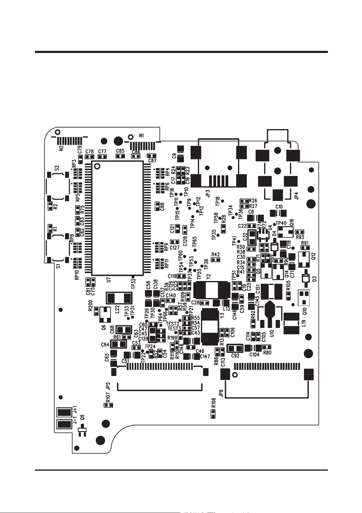
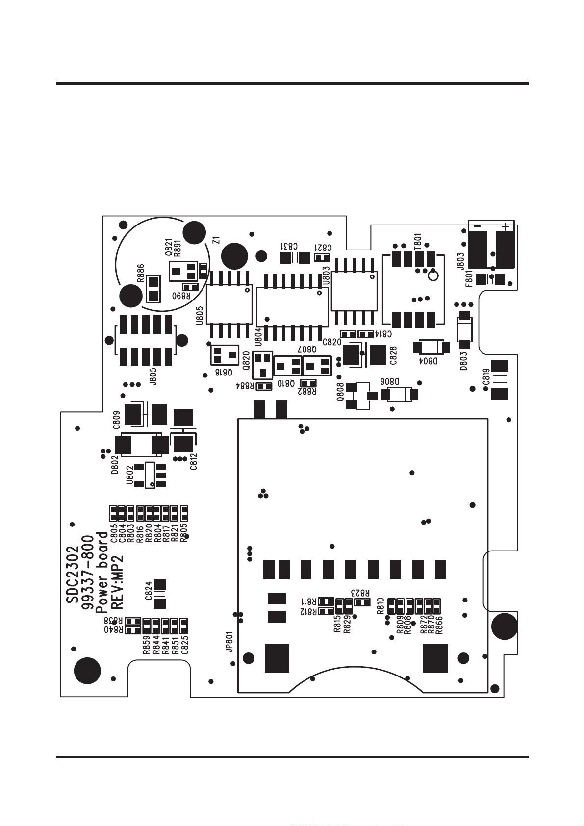
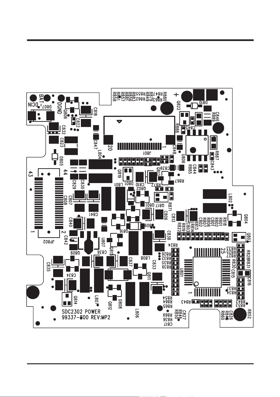
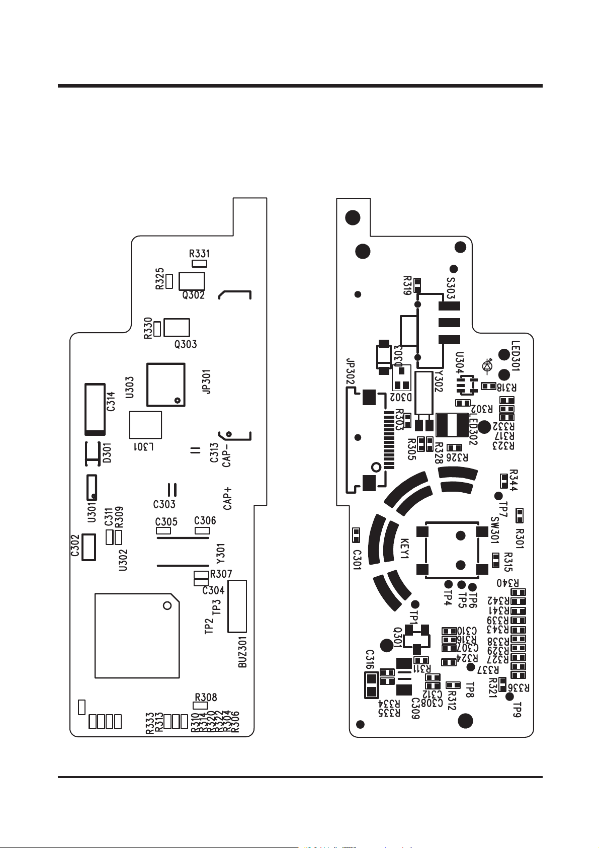
1. PARTS ARRANGEMENT FOR EACH PCB ASS’Y
1) MCU BOARD ASSEMBLY …………………………………………………………………………………34
2) POWER BOARD ASSEMBLY ……………………………………………………………………………36
3) SW1 BOARD ASSEMBLY …………………………………………………………………………………38
4) FLASH BOARD ASSEMBLY ………………………………………………………………………………39
5) JACK BOARD ASSEMBLY…………………………………………………………………………………40
6) CCD BOARD ASSEMBLY …………………………………………………………………………………41
7) SW2 BOARD ASSEMBLY …………………………………………………………………………………42
ⅥⅥ
.. TTRROOUUBBLLEESSHHOOOOTTIINNGG
1. BLOCK DIAGRAM ……………………………………………………………………………………………43
2. PRINCIPAL TROUBLESHOOTING ……………………………………………………………………………44
3. PARTS MODIFICATION ………………………………………………………………………………………46
4. PARTS EXPLAINTION OF EACH BOARD
1) MCU BOARD ASSEMBLY …………………………………………………………………………………48
2) POWER BOARD ASSEMBLY ……………………………………………………………………………50
3) SW1 BOARD ASSEMBLY …………………………………………………………………………………52
4) FLASH BOARD ASSEMBLY ………………………………………………………………………………53
5) JACK BOARD ASSEMBLY…………………………………………………………………………………54
5. DISASSEMBLE THE BARREL ASS'Y…………………………………………………………………………55
6. ASSEMBLE THE BARREL ASS'Y ……………………………………………………………………………60
Page 3
4
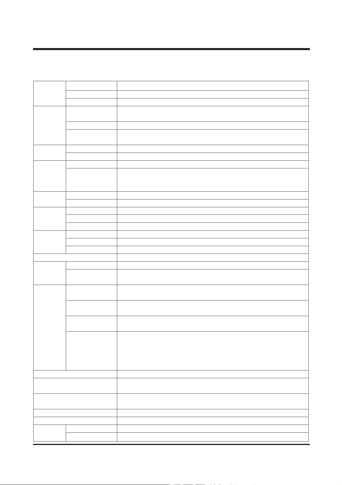
1. Specifications
Ⅰ
. SPECIFICATIONS
Image Type 1/3.2" CCD
Sensor Effective Pixels Approx. 2.0 Mega pixels
Total Pixels Approx. 2.1 Mega pixels
Lens Focal Length Samsung SHD lens f=5.2 ~ 15.6mm
(35mm film equivalent : 39~117mm)
F No. F2.8 ~ F4.8
Digital Zoom Still Image mode : 2X(Large size only)
Play mode : 2X
Viewfinder Optical Viewfinder Real image optical viewfinder
LCD Monitor 1.6" color TFT LCD
Focusing Type TTL auto focus, Manual focus
Range Normal : 80cm ~ infinity,
Macro : 30 ~ 80cm
TELE - 0.4m ~ 0.8m
Shutter Type Mechanical and Electronic shutter
Speed 1/2 ~ 1/2,000sec.
Exposure Control Program AE
Compensation ±2.0EV (0.5EV steps)
ISO Equivalent Auto
Flash Modes Auto/ Auto & Red-eye reduction / Slow synchro/ Fill-in/ Flash off
Range WIDE : 0.5 ~ 2.5m, TELE : 0.5 ~ 1.8m
Recharging Time Approx. 10 sec.
White Balance Auto / Daylight / Cloudy / Sunset / Tungsten / Fluorescent
Shooting Still Image
Single
Movie Clip Size : 320x240 pixels
Recording time : max. 3min.
Storage Media Internal memory : 8MB flash memory
External memory (Optional) : SD card (Up to 256MB guaranteed )
File Format Still Image : TIFF, JPEG(DCF), DPOF
Movie Clip : AVI(MJPEG)
Image Size L : 1600x1200 pixels
S : 800x600 pixels
Capacity (8MB) Large : Super fine 10, Fine 15, Normal 20
Small : Super fine 30, Fine 45, Normal 60
* These figures are measured by internal memory based.
These figures are measured under Samsung s standard conditions
and may vary depending on shooting conditions and camera settings.
Image Play Single image / Thumbnails / Slide show / Movie Clip
Interface Digital output connector : USB DC power input connector : 3.3V
Video output : NTSC / PAL (User selectable)
Power Source 2 x AA alkaline / 2 x Ni-MH / 2 x Ni-MN / CR-V3 batteries
AC adapter (Optional)
Dimensions (WxHxD) 110x61.5x41mm / 4.3x2.4x1.6in
Weight 180g / 6.3oz (without batteries and memory card)
Software Camera Driver Storage Driver (Windows98/98SE/2000/ME/XP. Mac OS 8.6 ~10.2)
Application MGI PhotoSuite, Digimax Viewer
Page 4

5
ⅠⅠ.. SS PP EE CC II FF IICC AA TTIIOO NN
2. System Requirements
PC with processor better thanMMXPentium 266MHz (XP : Pentium II 300MHz)
Windows 98/98SE/2000/ME/XP
Minimum 32MB RAM(XP : 128MB)
For Windows
110MB of available hard-disk space
USB port
CD-ROM drive
800x600 pixels, 16-bit color display compatible monitor
(24-bit color display recommended)
PowerMac G3 or later
MacOS 9.x ~ 10.2
Minimum 64MB RAM
110MB of available hard-disk space
For Macintosh
USB port
CD-ROM drive
QuickTime 4.0 or later for Movie Clip
Page 5
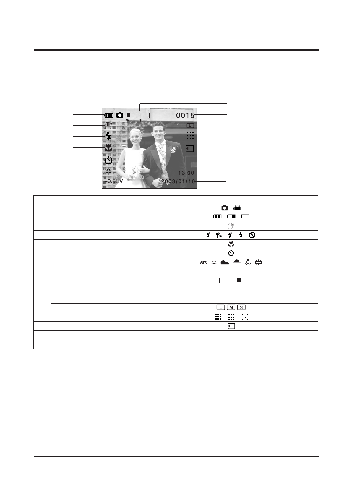
No. Description Icons
1 Recording mode
2 Battery
3 Camera shake warning
4 Flash
5 Macro indicator
6 Self-timer
7 White balance
8 Exposure compensation
+0.5 EV (Exposure Value)
9 Digital zoom( Large image size)
Number of available shots remaining(still image)
0015
Recording time(while recording a movie clip)
00:20
11 Image size
12 Quality
13 Memory card indicator
14 Time 13:00
15 Date 2003/01/10
6
3. TFT LCD Panel Mark
■ SHOT mode
ⅠⅠ.. SS PP EE CC II FF IICC AA TTIIOO NN
10
①
⑭
②
③
④
⑤
⑮
⑬
⑫
⑪
⑩
⑨
⑥
⑦
⑧
Page 6
7
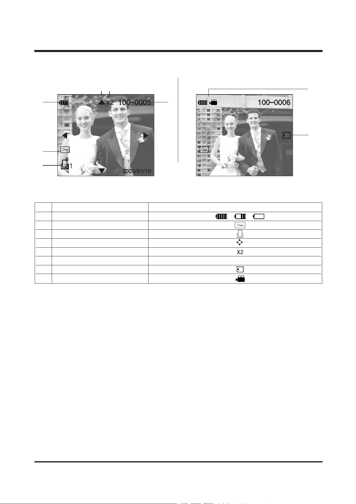
■ PLAY mode
【 Still image & Full Status 】【Movie clip & Full Status 】
① ⑥
⑦
⑧
②
③
④ ⑤
No. Description Icons
1 Battery
2 Protect indicator
3 DPOF indicator
4 Digital zoom indicator
5
Digital zoom magnification rate indicator
6 Number of stored images 100-0005
7 Memory card indicator
8 Movie clip indicator
ⅠⅠ.. SS PP EE CC II FF IICC AA TTIIOO NN
Page 7
8
ⅠⅠ.. SS PP EE CC II FF IICC AA TTIIOO NN
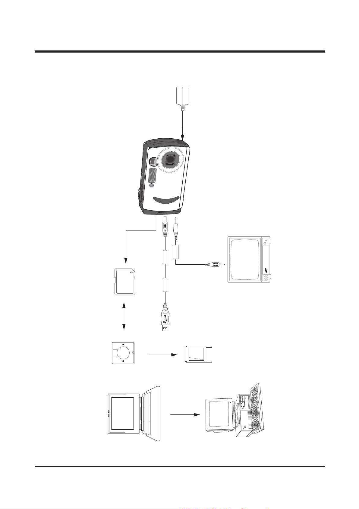
4. CONNECTION DIAGRAM
AC Adaptor
SD Card
Card Reader
Lap top
Video Cable
TV Monitor
USB Cable
PC Card Adaptor
IBM / MAC
Page 8
9
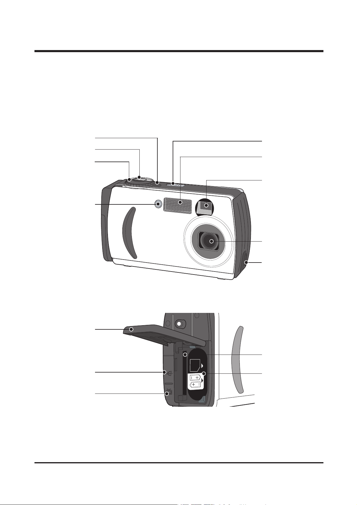
5.
Product Exterior
ⅠⅠ.. SS PP EE CC II FF IICC AA TTIIOO NN
Mode dial lamp
Shutter button
Mode dial
Self-timer lamp
Power switch
Flash
Viewfinder
Lens
DC input connection
point
Battery chamber
cover/
Memory card cover
USB connection
terminal
Video connection
terminal
Memory card slot
Battery chamber
Page 9
10
ⅠⅠ.. SS PP EE CC II FF IICC AA TTIIOO NN
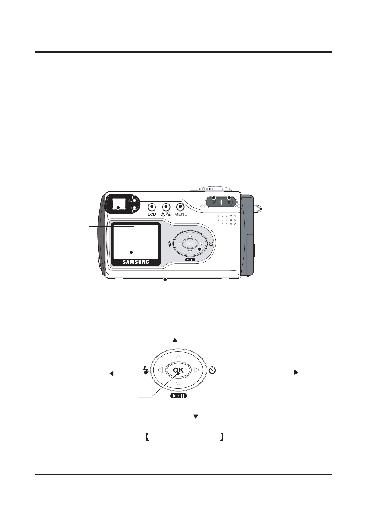
5-function button
LCD monitor
Tripod socket
Zoom(T) / Digital
zoom button
MENU button
Zoom(W) / Thumbna
button
Autofocus indicator
(Green) lamp
LCD button
MACRO/ DELETE
button
Strap eyelet
Viewfinder
FLASH/ LEFT( ) button
OK button
PLAY/STOP/ DOWN( ) button
5-function button
SELF-TIMER/ RIGHT( ) button
UP(
) button
Flash indicator(Red)
lamp
Page 10
11
ⅡⅡ
. INSTALLATION
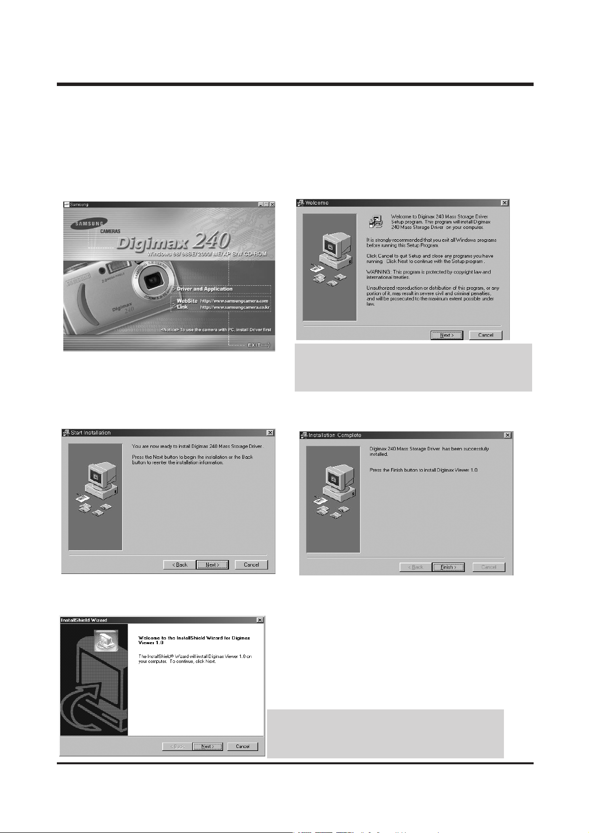
All application programs (Digimax Viewer 1.0 for viewing images, MGI PhotoSuite III SE for editing images,
and DirectX 8.1 for playing back movie clips) will be installed.
If you installed all application programs by clicking the [Driver Storage Driver], you need not install Digimax
Viewer 1.0 and MGI PhotoSuite III SE separately.
2. A [Welcome] window will open.
Click the [Next>] button.
1. Click [Storage Driver] menu on the Autorun frame.
3. A [start Installation] window will open.
Click the [Next>] button.
4. Installation is complete. Click the [Finish] button and the
[Digimax Viewer 1.0] installation will be started.
5. The [Digimax Viewer 1.0] installation window will be
displayed as shown below. Click [Next] button.
·If you select [Cancel] at the step 2, the camera driver
installation will be cancelled and a window for installing
Digimax Viewer 1.0 will be displayed.
If you select [Cancel] at the step 5, the Digimax Viewer 1.0
installation will be cancelled and a window for installing MGI
PhotoSuite III SE will be displayed.
Page 11
12
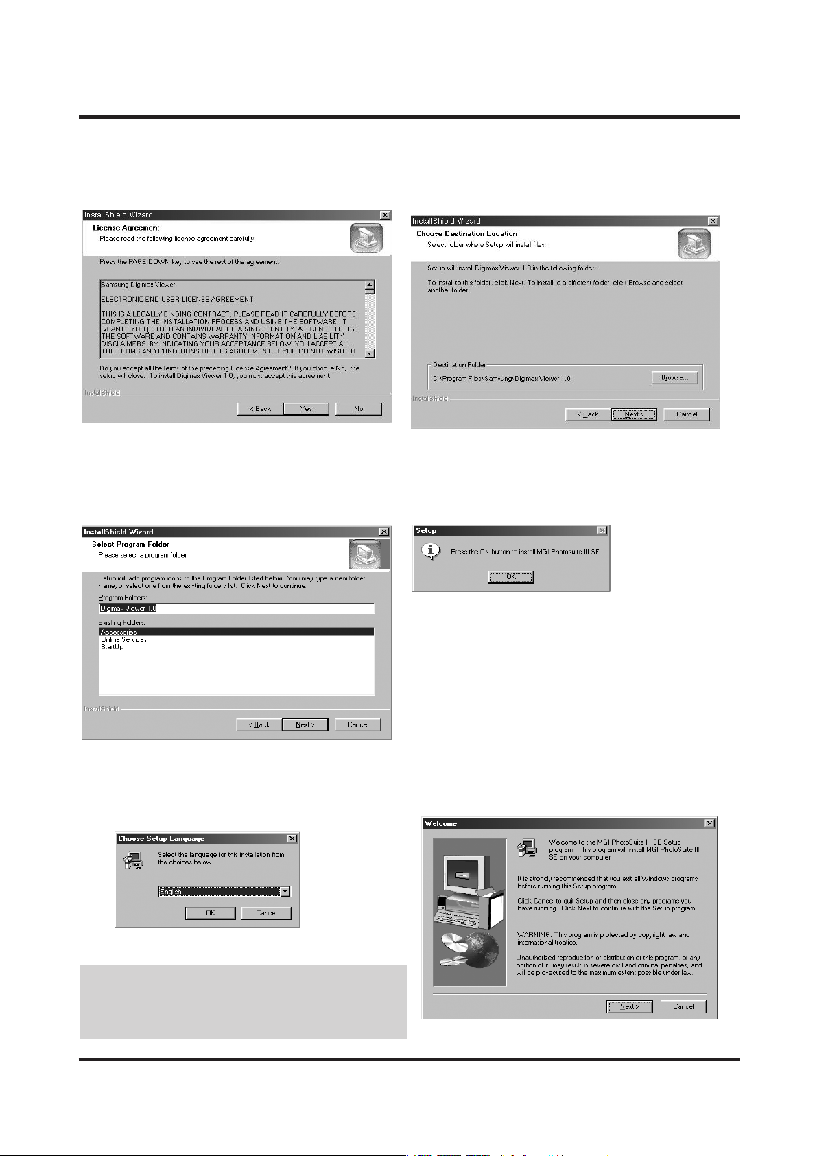
8. Select the Program folder and click [Next].
7. Select a destination folder and click [Next].
9. Installation is completed. Click [OK] button and the [MGI
PhotoSuite III SE] installation will be started.
10. The [Choose Setup Language] window will open.
Select a language and click [OK] button.
11. A [Welcome] window will be displayed. Click [Next>]
to move to the next step.
If you select [Cancel] at the step 10, the MGI PhotoSuite III
SE installation will be cancelled and a window for installing
DirectX 8.1 will be displayed.
6. The Software License Agreement window will display. If
you agree to it, click [Yes].
ⅡⅡ
.. II NN SSTTAALLLLAATTII OO NN
Page 12
13
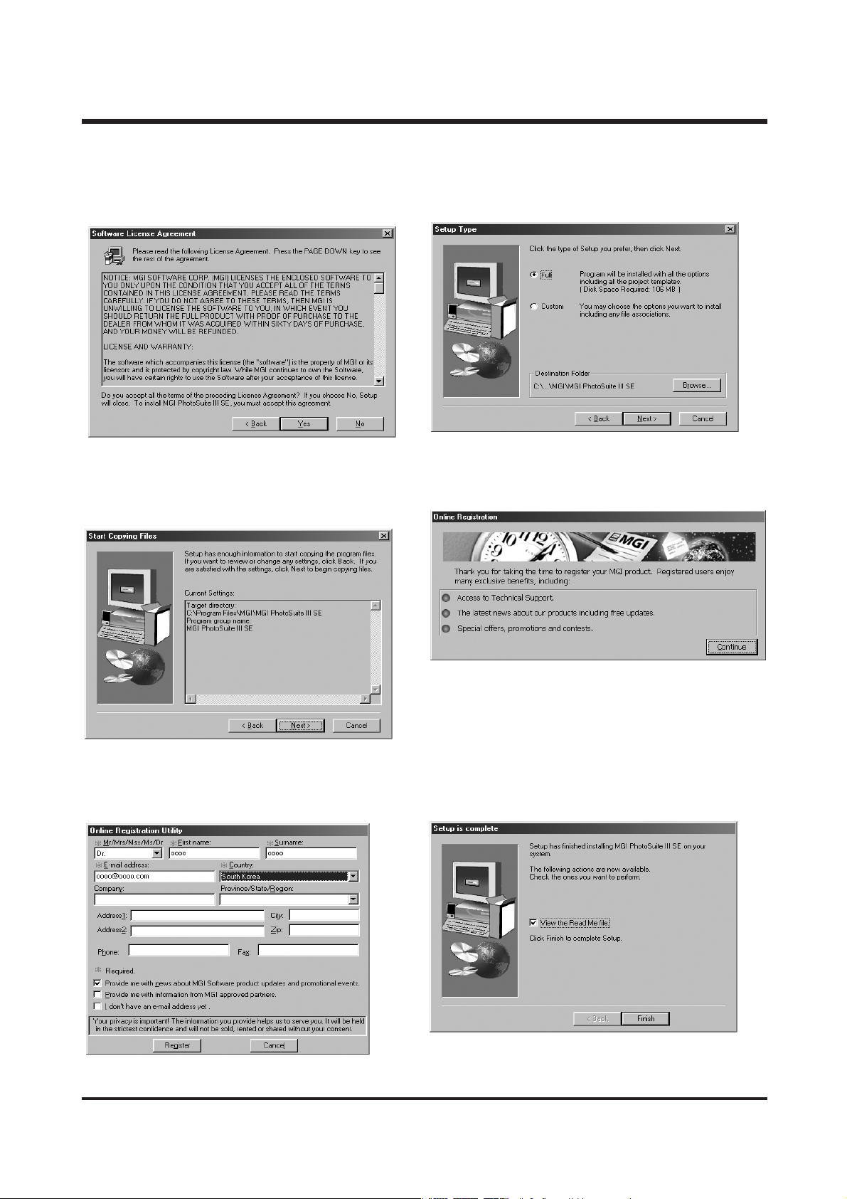
15. The MGI Registration window will be displayed. Click
the [Continue] button.
14. If the installation is completed correctly, the autoplay is
registered automatically into the start menu program as
shown below. Click [Next>] button.
13. A [Setup Type] window will open. Select setup type
and click [Next >] button.
12. The Software License Agreement window will be
displayed. If you agree to this, click [Yes] button.
16. The [Online Registration Utility] window will be
displayed. Fill in the blanks and click the [Register]
button.
17. Installation is complete. Click the [Finish] button.
ⅡⅡ
.. II NN SSTTAALLLLAATTII OO NN
Page 13
14
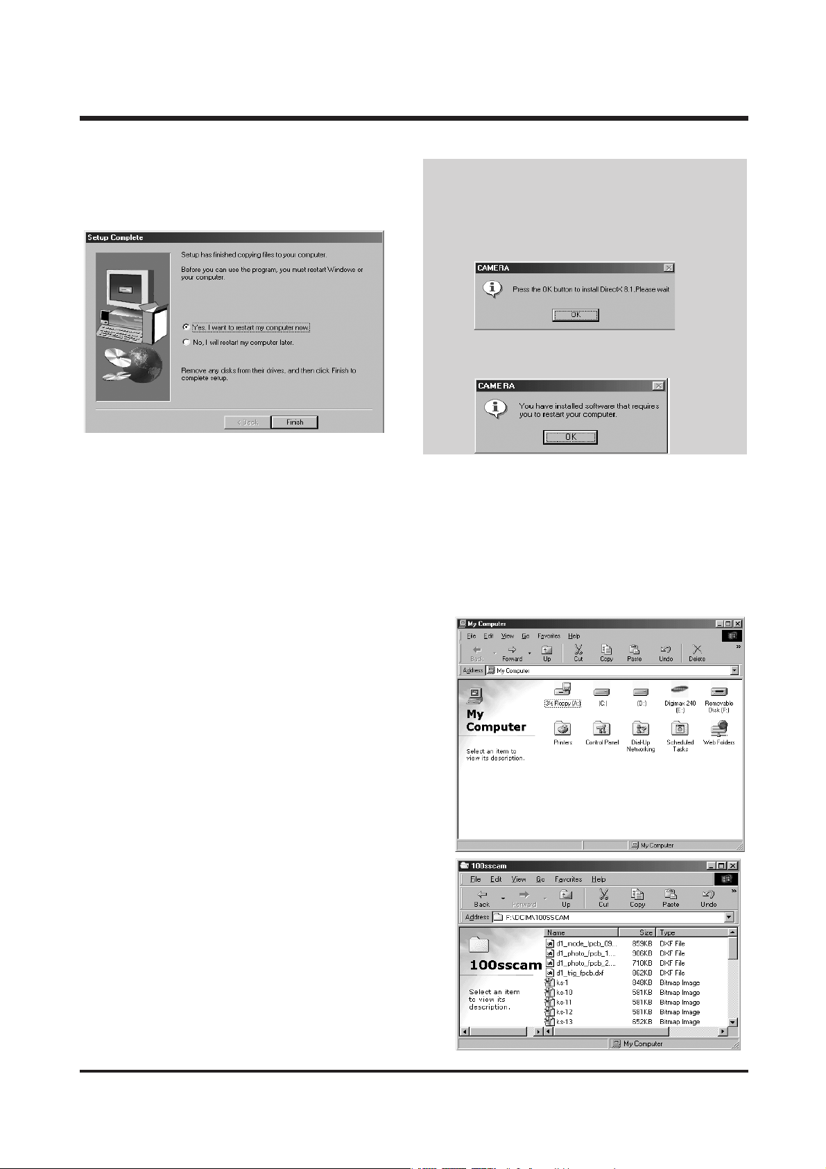
18. All application programs are installed correctly. Check
[Yes, I want to restart my computer now.] button and click
[Finish] button.
If you have ever installed the DirectX program in
your computer, the following windows will open.
18. The [DirectX 8.1] installation window will be
displayed as shown alongside. Click [OK] button.
19. All application programs are installed correctly.
Click [OK] button and the computer will restart.
20. After restarting the computer, connect the PC to the camera with the USB cable.
21. Turn the camera power on. [Found New Hardware Wizard] will open and the computer will recognize the camera.
※ If you have ever installed an image viewer program, the program will open. If the image viewer program opens,
the camera driver was setup successfully.
22. If you can see [Removable Disk] under [My computer], the
camera driver installation is successful.
Now you can transfer image files from the camera to PC via
the USB cable.
ⅡⅡ
.. II NN SSTTAALLLLAATTII OO NN
Page 14
15
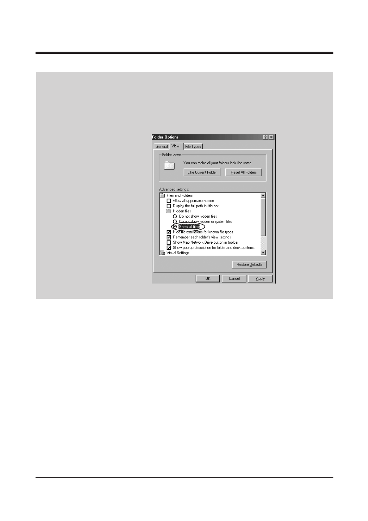
If you have installed the camera driver, [Found New Hardware Wizard] may not open.
After the [Found New Hardware Wizard] window opens, a window may open to select the camera driver file
location. In this case, select [C:\WINDOWS\INF\OTHER] folder. If you can’t find [INF\OTHER] folder, check
[Show all files] button in [Window's Explorer → View → Folder → option → View].
It is recommended that you use an AC adapter (Optional) when connecting the camera to a computer.
Before connecting the camera to the PC, You should first install the camera driver first.
ⅡⅡ
.. II NN SSTTAA LLLL AATT IIOO NN
Page 15
16
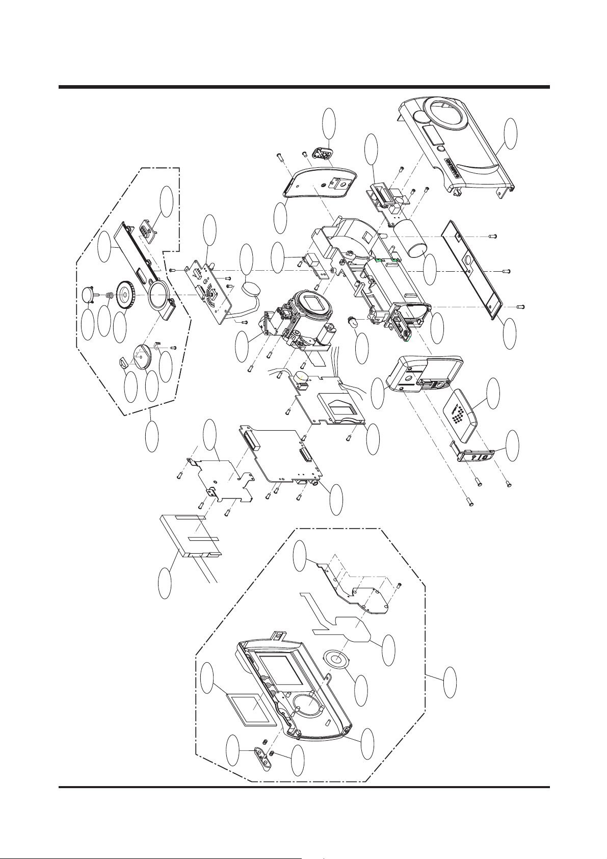
ⅢⅢ.. EEXXPPLLOODDEEDD VVIIEEWWSS AANNDD PPAARRTTSS LLIISSTT
11.. MMAA IINN AASSSS EEMMBBLL YY
1-5
1-19
1-14
1-11
1-22
1-24
1-23
1-36
1-7
1-15
1-25
1-26
1-27
1-16
1-17
1-4
1-3
1-28
1-29
1-10
1-30
1-18
1-6
1-32
1-20
1-12
1-21
1-2
1-13
1-33
1-9
1-35
1-1
1-8
1-31
1-34
Page 16

17
ⅢⅢ.. EEXXPP LL OO DD EE DD VVII EE WWSS AA NNDD PPAA RRTT SS LL IISS TT
▶▶
PARTS LIST
1-1 9010-0492-01A 5 WAY BUTTON 1
1-2 7217-2828-01A BATTERY COVER 1
1-3 7217-2829-01A DOWN COVER 1
1-4 9007-1906-01A FRONT COVER ASS'Y-KENOX DIGIMAX 240 1
9007-1907-01A FRONT COVER ASS'Y-DIGIMAX 240 1
1-5 7217-2830-01A DC RUBBER 1
1-6 7017-0368-01A LCD FRAME 1
1-7 7217-2831-01A BATTERY HOLDER 1
1-8 9007-1908-01A REAR COVER ASS'Y 1
1-9 7217-2832-01A LCD PROTECTOR 1
1-10 9007-1909-01A TOP COVER ASS'Y 1
1-11 7217-2833-01A LEFT COVER 1
1-12 7217-2834-01A RIGHT COVER 1
1-13 7217-2835-01A USB COVER 1
1-14 7217-2836-01A POWER SWITCH 1
1-15 7411-1000-01A STRAP HOLDER 1
1-16 7217-2837-01A BUZZER 1
1-17 9002-1189-01A LENS MODULE ASS'Y 1
1-18 9008-0615-01A LCD ASS'Y 1
1-19 9008-0616-01A FLASH BOARD ASS'Y 1
1-20 9008-0617-01A MAIN BOARD ASS'Y 1
1-21 9008-0618-01A POWER BOARD ASS'Y 1
1-22 9008-0619-01A SWITCH 1 BOARD ASS'Y 1
1-23 9008-0620-01A JACK BOARD ASS'Y 1
1-24 7217-2838-01A TOP COVER 1
1-25 6107-0538-01A SHUTTER BUTTON BASE 1
1-26 7217-2839-01A RELEASE BUTTON 1
1-27 7217-2840-01A MODE DIAL HOLDER 1
1-28 7017-0369-01A MODE DIAL PLATE 2
1-29 7217-2841-01A MODE DIAL SET 1
1-30 7017-0370-01A MODE DIAL 1
1-31 9007-1910-01A BACK COVER ASS'Y 1
1-32 7217-2842-01A FPCB HOLDER 1
1-33 4102-0072-01A SW2 FPC 1
1-34 6107-0539-01A SPRING 2
1-35 7217-2843-01A ZOOM BUTTON 1
1-36 2501-0004-01A CAPACITOR 1
Fig.No. Parts No. Parts Name Q'ty Remarks
Page 17
18
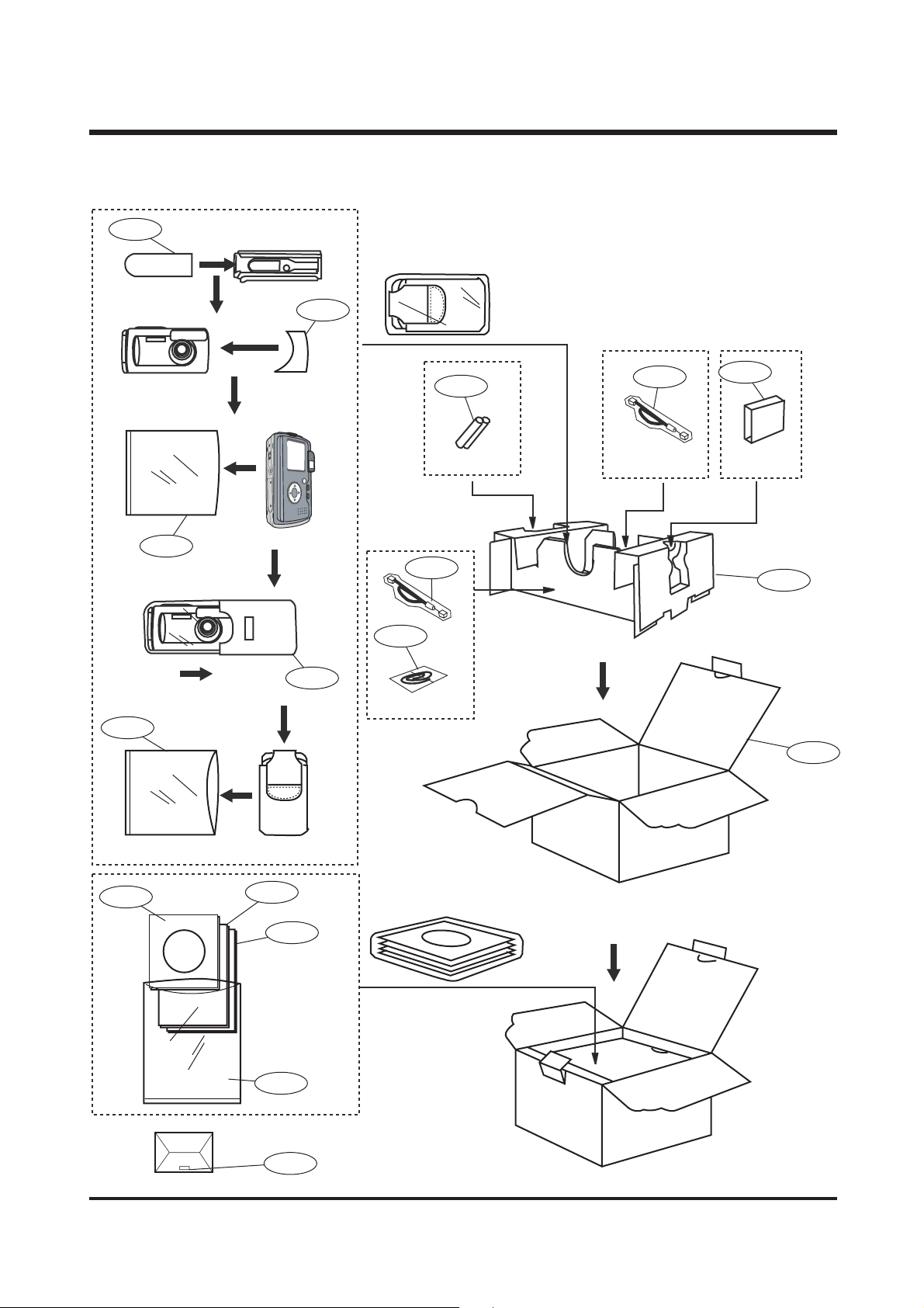
22.. PP AACCKKIINNGG IITTEEMM
ⅢⅢ.. EEXXPP LL OO DD EE DD VVII EE WWSS AA NNDD PPAA RRTT SS LL IISS TT
2-1
2-2
2-5
2-3
2-4
2-11
2-10
2-14
2-12
2-13
2-15
2-16
2-6
2-7
2-8
2-9
2-17
Page 18

19
▶▶
PARTS LIST
ⅢⅢ.. EEXXPP LL OO DD EE DD VVII EE WWSS AA NNDD PPAA RRTT SS LL IISS TT
Fig.No. Parts No. Parts Name Q'tY Remarks
2-1 7409-1303-01A FCC LABEL(MADE IN CHINA) 1
7409-1304-01A FCC LABEL(MADE BY SAMSUNG) 1
7409-1305-01A MIC LABEL_KENOX D 101 1
2-2 6804-0444-01A PRODUCT STICKER 1
2-3 P960-2240-01A PE BAG(FOR CAMERA) 1
2-4 6904-0237-01A POUCH 1
2-5 6901-1697-01A G/T BOX_KENOX_D 240_KOR 1
6901-1698-01A G/T BOX_DIGIMAX 240 1
6901-1699-01A G/T BOX_USA/CAN 1
2-6 4609-0040-01A DRIVER + MGI PHOTOSUITE(E/F/G/S/I/DUT/P) 1
4609-0041-01A DRIVER + MGI PHOTOSUITE(E/JPN/T.C/S.C/KOR) 1
2-7 6807-0026-01E WARRANTY CARD_KOR 1
6807-0030-03O WARRANTY CARD 1
6807-0038-02D WARRANTY CARD_UK 1
6807-0109-02B WARRANTY CARD_RUS 1
6807-0113-01A WARRANTY CARD_CHI 1
6807-0095-02D CARD PRODUCT_MEXICO 1
2-8 6806-1383-01A USER MANUAL_KENOX_D 101 1
6806-1384-01A USER MANUAL_ENG 1
6806-1385-01A USER MANUAL_GER 1
6806-1386-01A USER MANUAL_FRA 1
6806-1387-01A USER MANUAL_SPA 1
6806-1388-01A USER MANUAL_ITA 1
6806-1389-01A USER MANUAL_CHI(T) 1
6806-1390-01A USER MANUAL_DUT 1
6806-1391-01A USER MANUAL_POR 1
6806-1392-01A USER MANUAL_SWE 1
6806-1393-01A USER MANUAL_DEN 1
6806-1394-01A USER MANUAL_FIN 1
6806-1395-01A USER MANUAL_RUS 1
6806-1396-01A USER MANUAL_CHI(S) 1
2-9 6909-0116-01A PE BAG(FOR ACCESSORY) 1
2-10 3801-0016-01A USB CABLE 1
2-11 7409-1217-01A STRAP 1
2-12 4602-0004-01A SD CARD_16MB 1
4602-0006-01A SD CARD_32MB 1
2-13 4301-0018-01A BATTERY 1
2-14 6901-1692-01A INNER PAD 1
6806-1428-01A QUICK GUIDE_KOR 1
6807-0108-01A U.K_VOUCHER 1
6804-0063-01G A/S STICKER_KOR 1
6804-0088-01A SECURITY STICKER_USA 1
6804-0377-01A TECH/SUPPORT(DSC_USA) 1
7409-0637-01A SAFETY_RUSSIA 1
Page 19
20
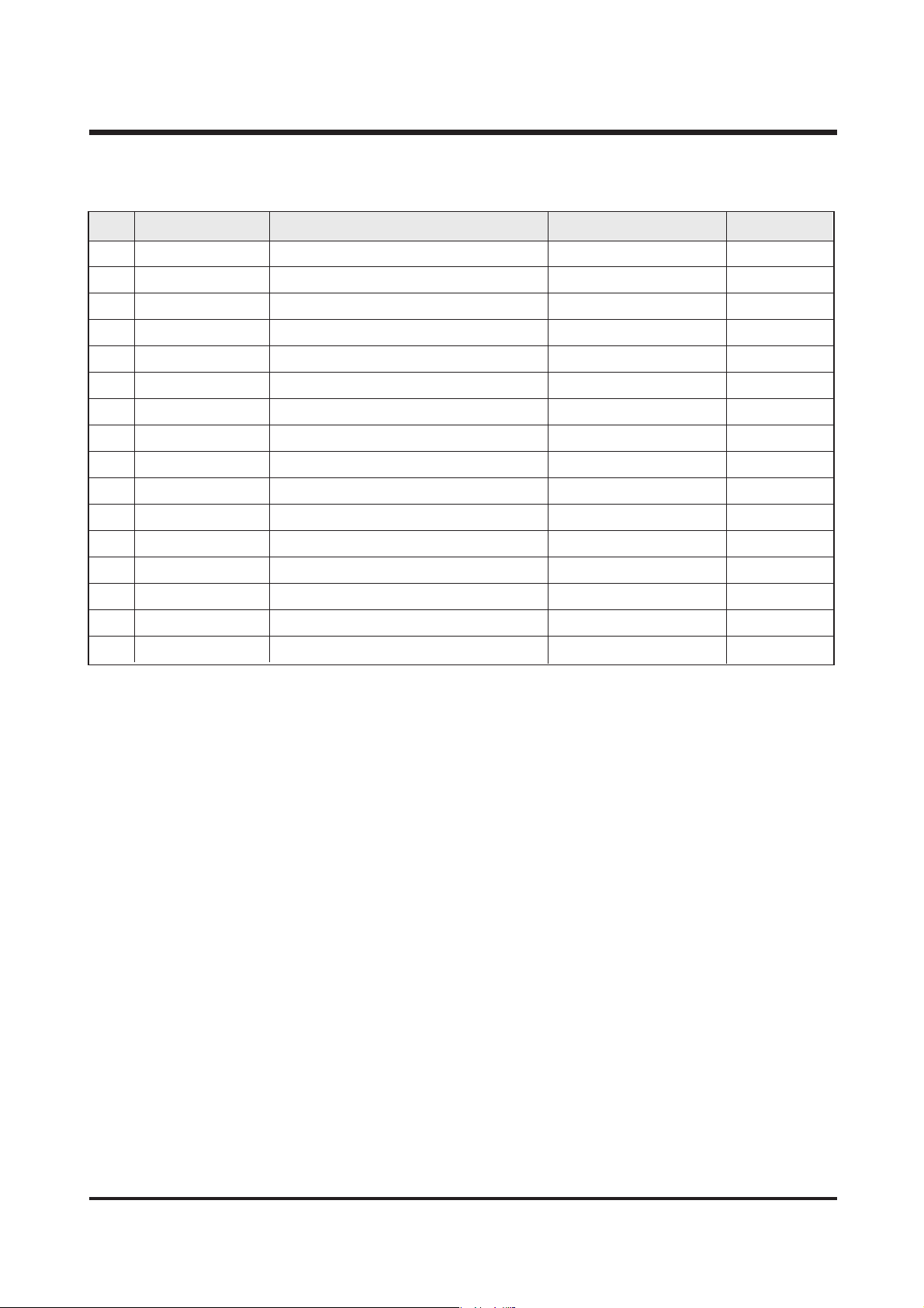
3. INITIAL PARTS LIST
ⅢⅢ.. EEXXPP LL OO DD EE DD VVII EE WWSS AA NNDD PPAA RRTT SS LL IISS TT
N O PARTS NO. PARTS NAME SPEC PAGE
1 9007-1906-01A FRONT COVER ASS'Y KENOX DIGIMAX 240 16
2 9007-1907-01A FRONT COVER ASS'Y DIGIMAX 240 16
3 9007-1910-01A BACK COVER ASS'Y 16
4 7217-2828-01A BATTERY COVER 16
5 7217-2835-01A USB COVER 16
6 7217-2833-01A LEFT COVER 16
7 7217-2834-01A RIGHT COVER 16
8 9008-0615-01A LCD ASS'Y 16
9 9002-1189-01A LENS MODULE 16
10 7217-2830-01A DC RUBBER 16
11 3601-0005-01A FUSE 38
12 3722-0015-01A DC JACK 16
13 3722-0013-01A USB JACK 37
14 7217-2838-01A TOP COVER 16
15 7217-2839-01A RELEASE BUTTON 16
16 7017-0370-01A MODE DIAL 16
Page 20
21
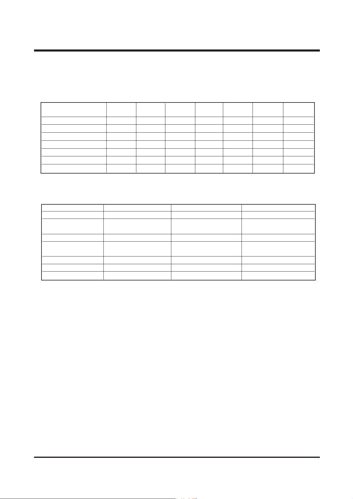
1. Replacement Parts and Adjustment Items
Digimax 240 requires electrical adjustments when certain parts are replaced.
The table below indicates the adjustments required for the respective part replacements.
2. Adjustment Tools
The following tools are required for electrical adjustment.
▶ Program
Please contact to our website (www.ssa.net) and download the each programs.
- Firmware : Latest version
- Test program : [ Sys2300_TestModeOn.cfg], [ Sys2300_TestModeOff.cfg]
▶ Equipment
- Light source
- AE Tester : Adjust at LV 9.0 and check the flash on at LV 9.5, or flash off at LV 10.0.
▶ Chart
- Focus chart : Please contact to our website (www.ssa.net) and print the focus Chart on the
paper from the “101CHART.pdf ”
- Gray chart : Standard 31% Gray Chart.
MCU Power Flash SW1 Jack Lens TFT LCD
board board board board board module
Update Firmware ○○
AWB,AE adjustment ○
Focus adjustment ○○
Trig adjustment ○○
Strobo adjustment ○○
LCD adjustment ○○
Burnin check ○○ ○○○○
ⅣⅣ.. AADDJJUUSSTTMMEENNTT
Program Equipment Chart
Update Firmware Firmware
AWB / AE Light source
adjustment 5100。K
Focus adjustment Focus chart
Trig adjustment AE Tester
LV 9.0, 9.5, 1.0
Strobo adjustment Dark room Gray reflector
LCD adjustment
Burnin check AC Aadptor
Page 21
22
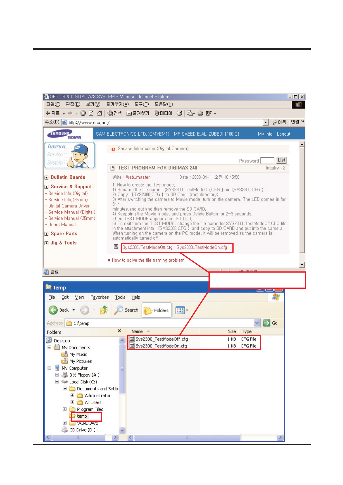
3. How to creat the Test Mode
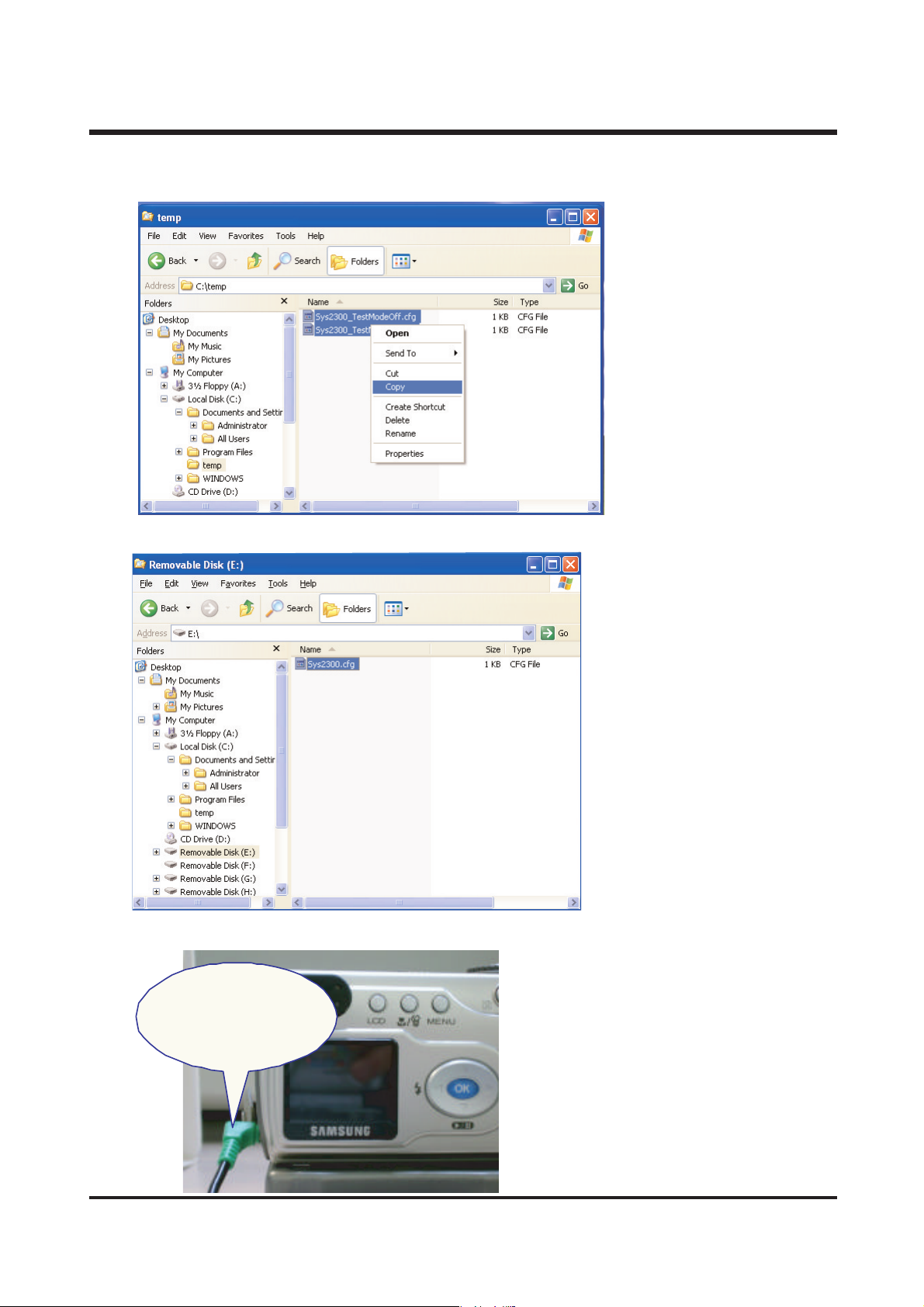
1) Please contact to our website (www.ssa.net) and download the test programs.
Please downloade the these files form
our web to temp folder in your PC.
ⅣⅣ.. AADD JJUUSS TT MM EE NNTT
Page 22
23
2) Copy [ Sys2300_TestModeOn.cfg] to SD card.
3) Rename the file name [Sys2300_TestModeOn.cfg] => [Sys2300.cfg]
4) Be sure to AC adaptor.
ADAPTER
(3.3V / 2.5A)
AC
ⅣⅣ.. AADD JJUUSS TT MM EE NNTT
Page 23
24
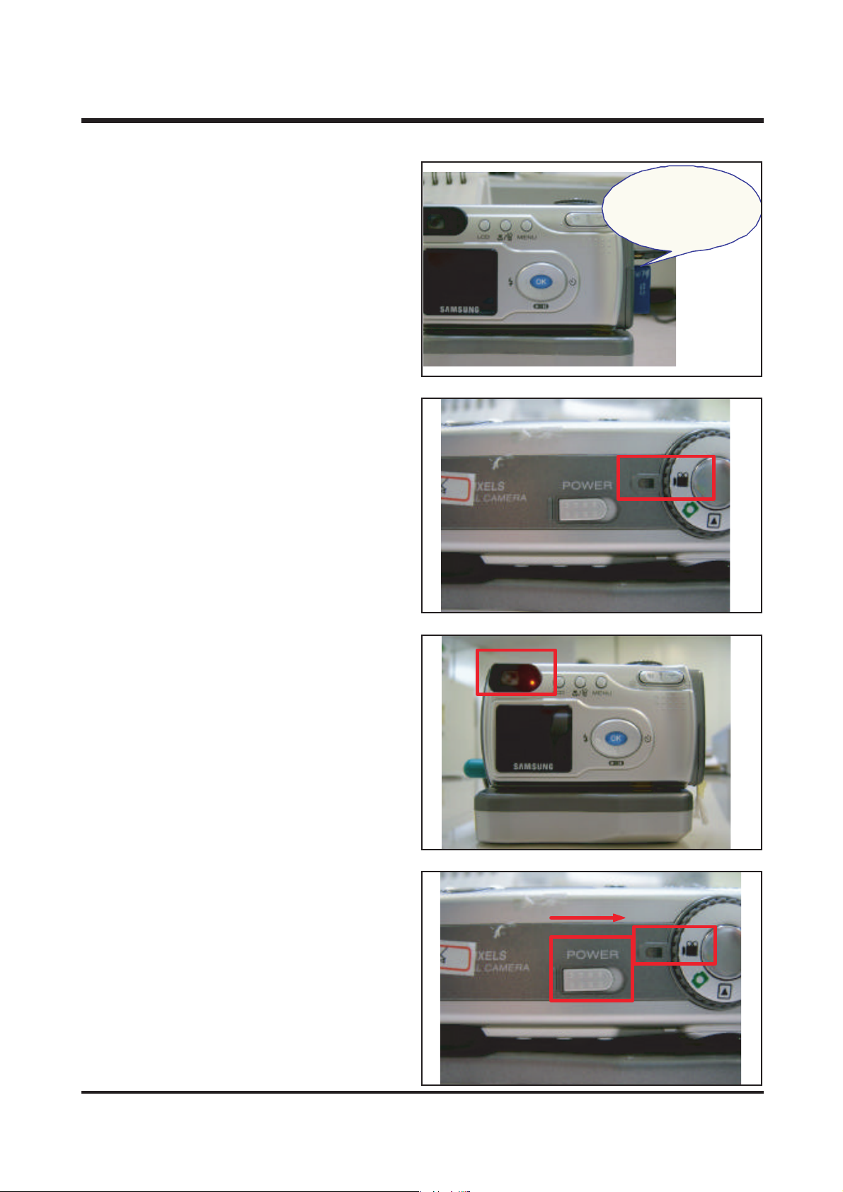
TEST PROGRAM
(SYS2300.CFG)
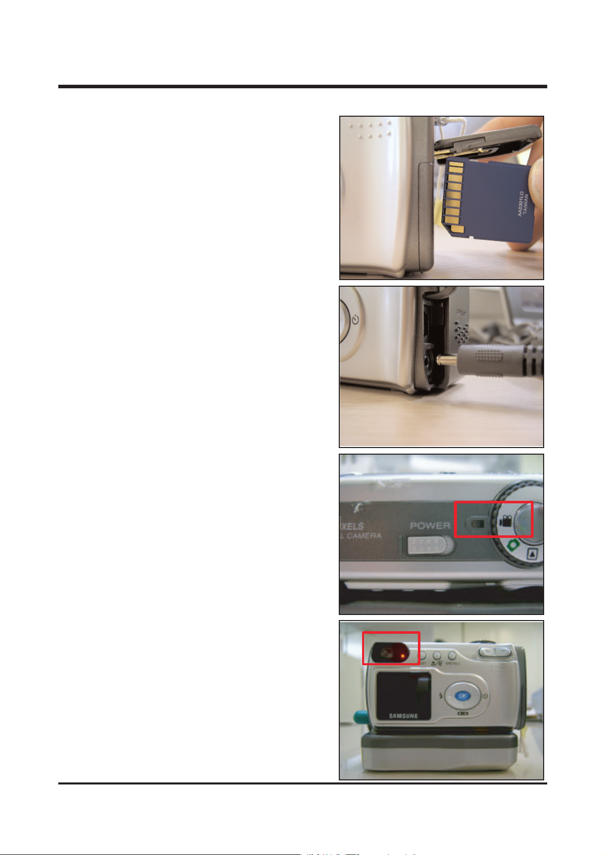
5) Insert the SD card with test program in
the camera.
6) Set the mode dial to MOVIE record mode.
7) Power On.
Then the LED lighting in for 3~4 min.,
and camera is turned off automatically.
Remove the SD card.
8) Turn on the camera again.
Keep the movie mode.
ⅣⅣ.. AADD JJUUSS TT MM EE NNTT
Page 24
25
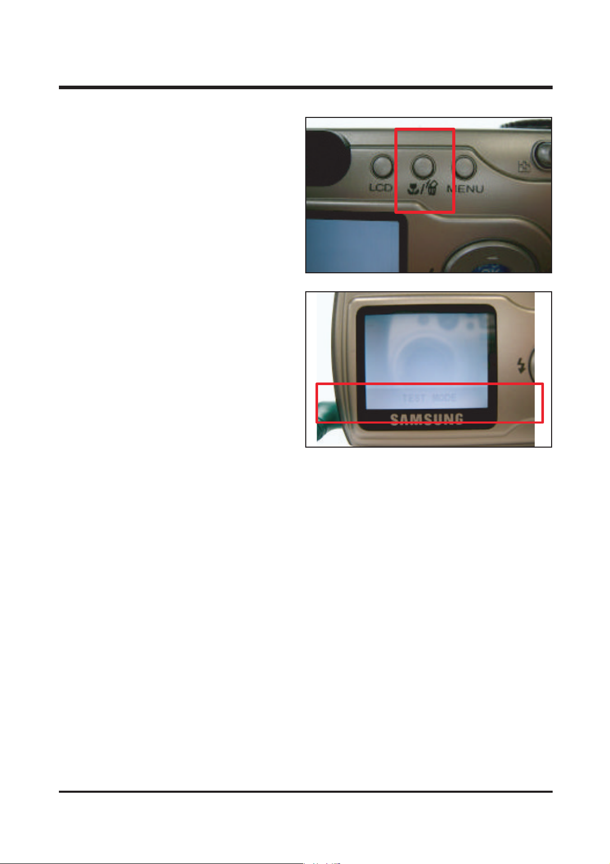
9) Press the Delete button for 2~3 seconds.
10) TEST MODE appears on TFT LCD.
11) To exit from test mode, change the file name for [Sys2300_TestMideOff.cfg] fileinto
[Sys2300.cfg] and copy to SD card and then insert the camera.
When turn on the camera on the Movie mode, it will be removed as the camera is
automatically turned off.
4. Test mode of that kinds.
1) TFT LCD Adjustment
2) AWB , AE Adjustment
3) AF Adjustment
4) STROBO FLASH LEVEL Adjustment
5) TRIG Adjustment
ⅣⅣ.. AADD JJUUSS TT MM EE NNTT
Page 25
26
ⅣⅣ.. AADD JJUUSS TT MM EE NNTT
4. Ffirmware version check.
1) Please contact to our website (www.ssa.net) and download the[Sys2300Test_On.cfg]
to SD card.
2) Rename the file name [Sys2300_TestModeOn.cfg] => [Sys2300.cfg]
3) Insert the SD card with test program in the camera.
4) Set the mode dial to MOVIE record mode.
5) Power on. Then the LED lighting in for 3~4 min., and camera is turned off automatically.
Remove the SD card.
6) Power on again. Press the UP(▲) button for 4~5 seconds.
Then camera information appears on TFT LCD.
7) You can see the Firmware version as below figure.
F/W VERSION : 0.125T is firmware ver.( 0.124T).
8) To exit from firmware check. Camera power off.
5. Ffirmware upgrade.
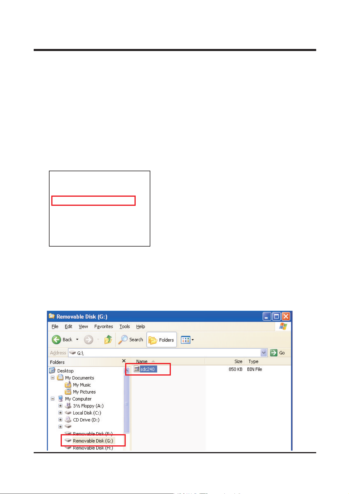
1) Please contact to our website (www.ssa.net) and download the latest firmware to SD card.
2) It will be changed the file name after downloading, please rename to the sdc230.bin
CCAA MMEE RRAA
TTYYPPEE :: DD--224400
DDAATTEE :: 0033//1144//22000033
FF//WW VVEERRSSIIOONN :: 00.. 112255TT
SS--DDAATTEE :: 1100//2299//22000011
SSUUBB VVEERRSSIIOONN :: 11..0099
Page 26
27
3) Insert the SD card including firmware in
a camera like right figure.
4) Connecting the AC adaptor.
5) Set the mode dial to Movie record mode.
6) Turn on the camera and you will se the
LED's on.
7) I f LED is off. turn off the power and
remove the SD card.
8) Please format the SD card then use it.
ⅣⅣ.. AADD JJUUSS TT MM EE NNTT
Page 27
28
ⅣⅣ.. AADD JJUUSS TT MM EE NNTT
6. Adjustment method for each item.
1) Focus adjustment
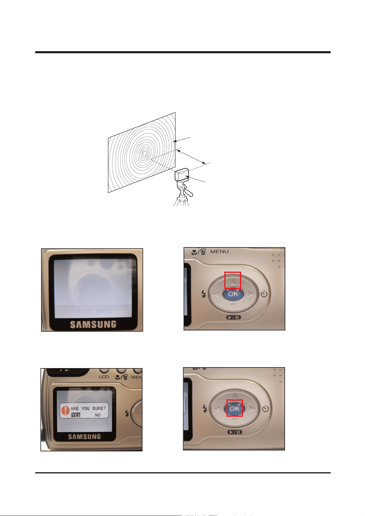
a. Set up a camera like below picture.(Download a Focus chart from ssa.net)
b) Make a test mode. (Refer to 26 page) c) Press the UP(▲) button.
d) The following message appears. e) Press the OK button.
You should have set the camera before press
the OK button
Far focus : 3m
Normal focus : 40cm
Focus Chart
Tripod
Camera
Page 28
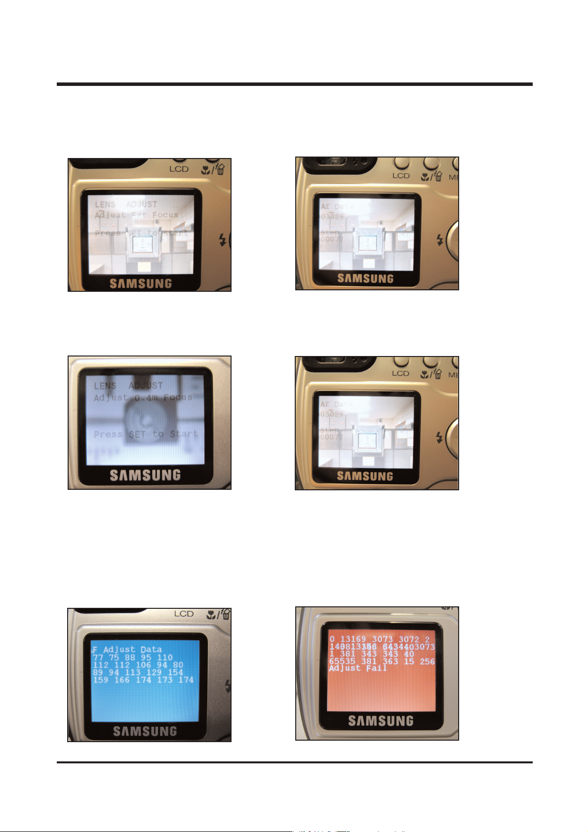
f) If you press OK button. g) And camera set the 3m from AF chart and
It will be displayed as following figure. then press the OK button.
It will be adjusted automatically.
h) Finished the FAR Focus. i) And camera set the 40cm from AF chart and
It will be displayed as following figure. then press the OK button.
It will be adjusted automatically.
j) Finished the 0.4m Focus.
It will appears AF Adjust Data as follows.
If adjusted error it will be appears RED screen. (Adjust again)
Blue screen : OK Red screen : NG
29
ⅣⅣ.. AADD JJUUSS TT MM EE NNTT
Page 29
30
ⅣⅣ.. AADD JJUUSS TT MM EE NNTT
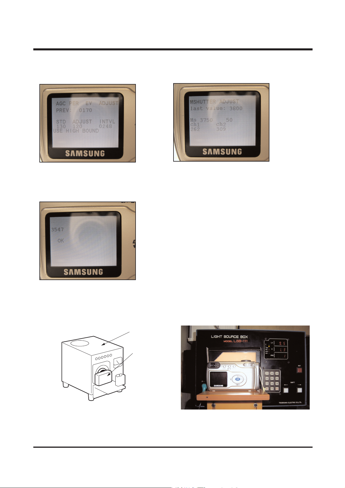
2) AE & AWB adjustment
a. Set up a camera like below picture.(Download a Focus chart from ssa.net)
(Color temperature : 5600。± 300。K
Brghtiness : 4000±800LUX)
b) Make a test mode. (Refer to 26 page) c) Press the DOWN(▼) button.
d) The following message appears. e) Press the OK button.
You should have set the camera before press
the OK button
Camera
Light source
Page 30
31
ⅣⅣ.. AADD JJUUSS TT MM EE NNTT
f) If you press OK button. g) Finish the EV adjusting, it adjusting the
Then EV will be adjusted automatically.. M-Shutter.
h) Finished the EV and M-Shutter adjusted.
It will be displayed OK as following figure.
If FAIL apperas, please readjust.
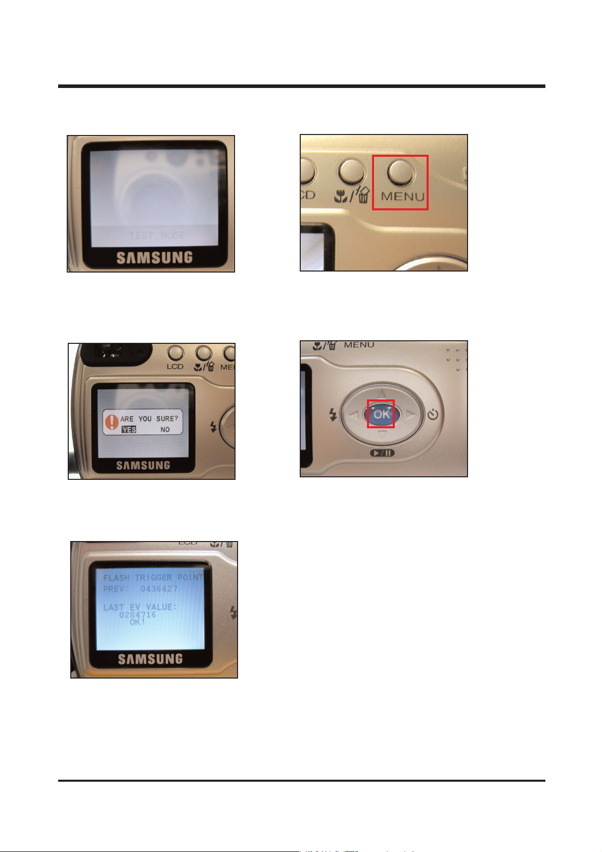
3) TRIGGER adjustment
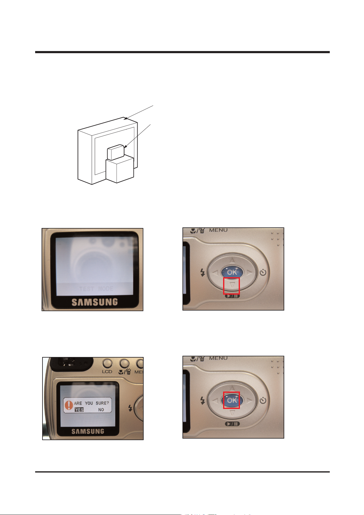
a. Set up a camera like below picture.(Download a Focus chart from ssa.net)
※ Set the AE Teste at LV 9.5
AE Tester
Camera
Page 31
32
ⅣⅣ.. AADD JJUUSS TT MM EE NNTT
b) Make a test mode. (Refer to 26 page) c) Press the MENU button.
d) The following message appears. e) Press the OK button.
You should have set the camera before press
the OK button
f) If you press OK button.
Then FLASH TRIGGER will be adjusted automatically.
If FAIL apperas, please readjust.
※ After the adjustment is completed, check the flashing point.
Flash on : LV 9
Flash off : LV 10
Page 32
33
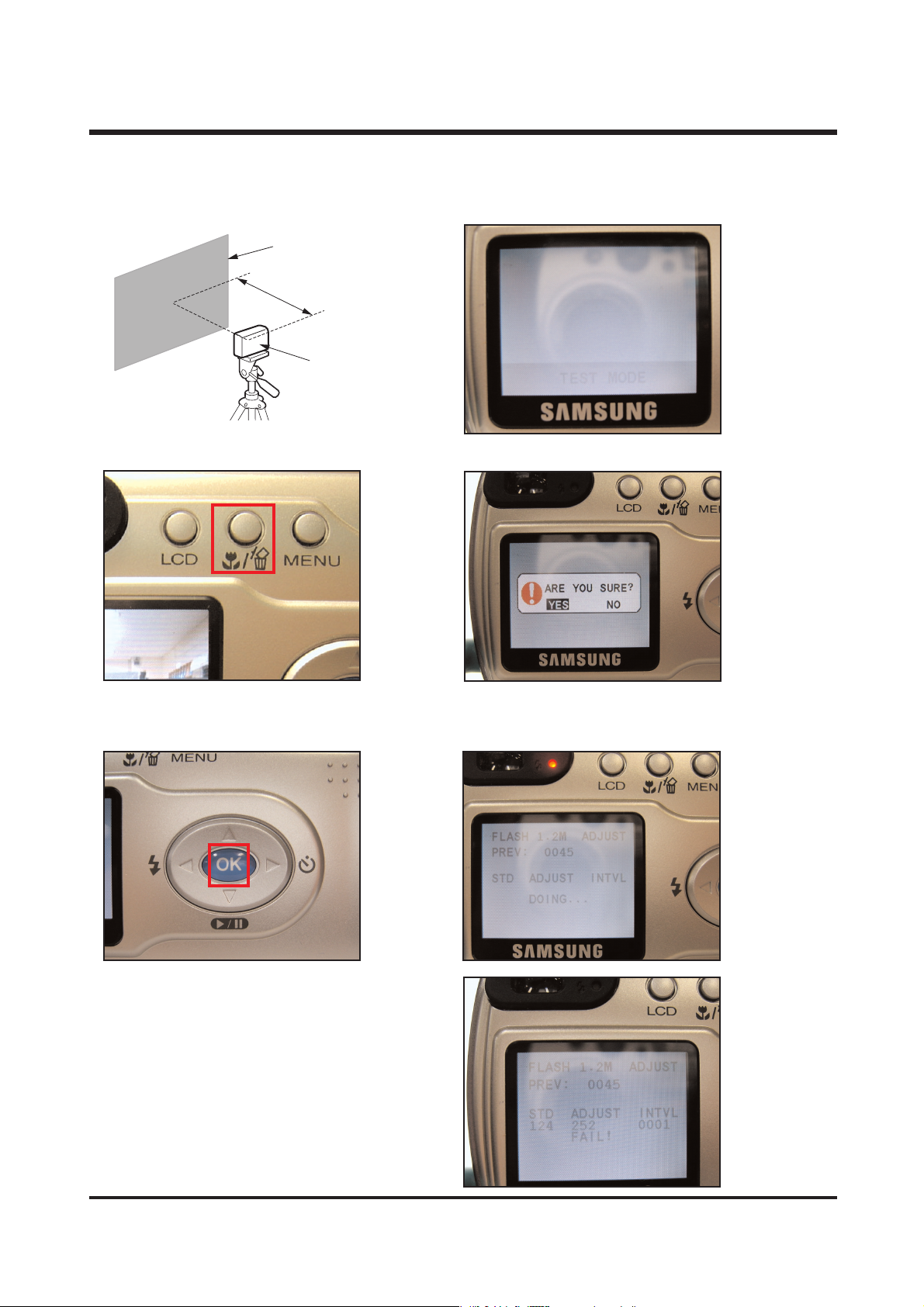
4)STROBO adjustment
a. Set up a camera like below picture. b) Make a test mode. (Refer to 26 page)
c) Press the MACRO/DELETE button. d) The following message appears.
e) Press the OK button. f) If you press OK button.
You should have set the camera before press Then STROBO will be adjusted automatically.
the OK button
g) Finish the STROBO adjusted,
It will be displayed OK as following figure.
If FAIL apperas, please readjust.
1.2m
Reflector paper
Tripod
Camera
ⅣⅣ.. AADD JJUUSS TT MM EE NNTT
Page 33
34
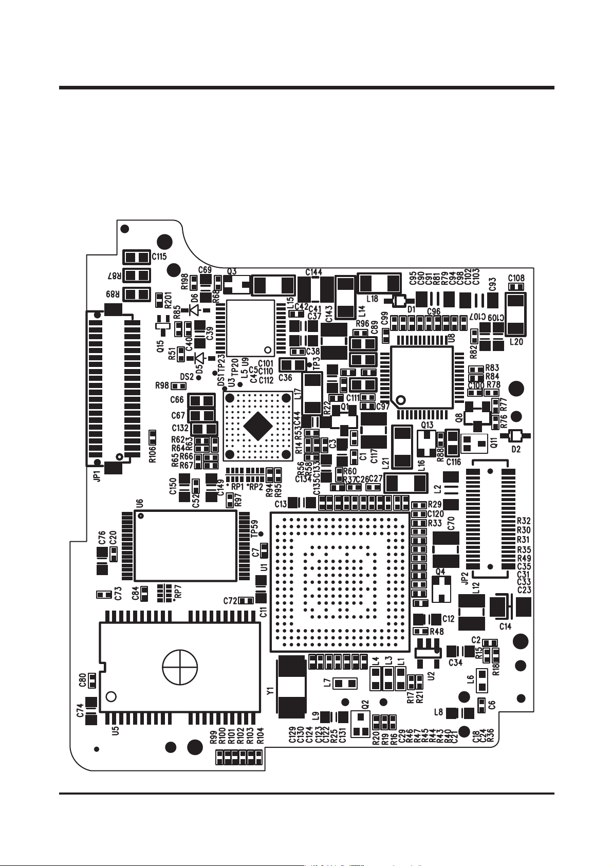
1.
PARTS ARRANGEMENT FOR EACH PCB ASS'Y
1)MAIN
BOARD
Assembly
a) Parts Arrangement
<TOP>
Ⅴ. PRODUCT CONSTRUCTION
Page 34
35
<BOTTOM>
ⅤⅤ.. PPRR OODD UUCC TT CCOONN SSTT RR UU CCTT IIOONN
Page 35
36
2) POWER
BOARD
Assembly
a) Parts Arrangement
<TOP>
ⅤⅤ.. PPRR OODD UUCC TT CCOONN SSTT RR UU CCTT IIOONN
Page 36
37
ⅤⅤ.. PPRR OODD UUCC TT CCOONN SSTT RR UU CCTT IIOONN
<BOTTOM>
Page 37
38
3) SW1
BOARD
Assembly
a) Parts Arrangement
<TOP>
<BOTTOM>
ⅤⅤ.. PPRR OODD UUCC TT CCOONN SSTT RR UU CCTT IIOONN
Page 38
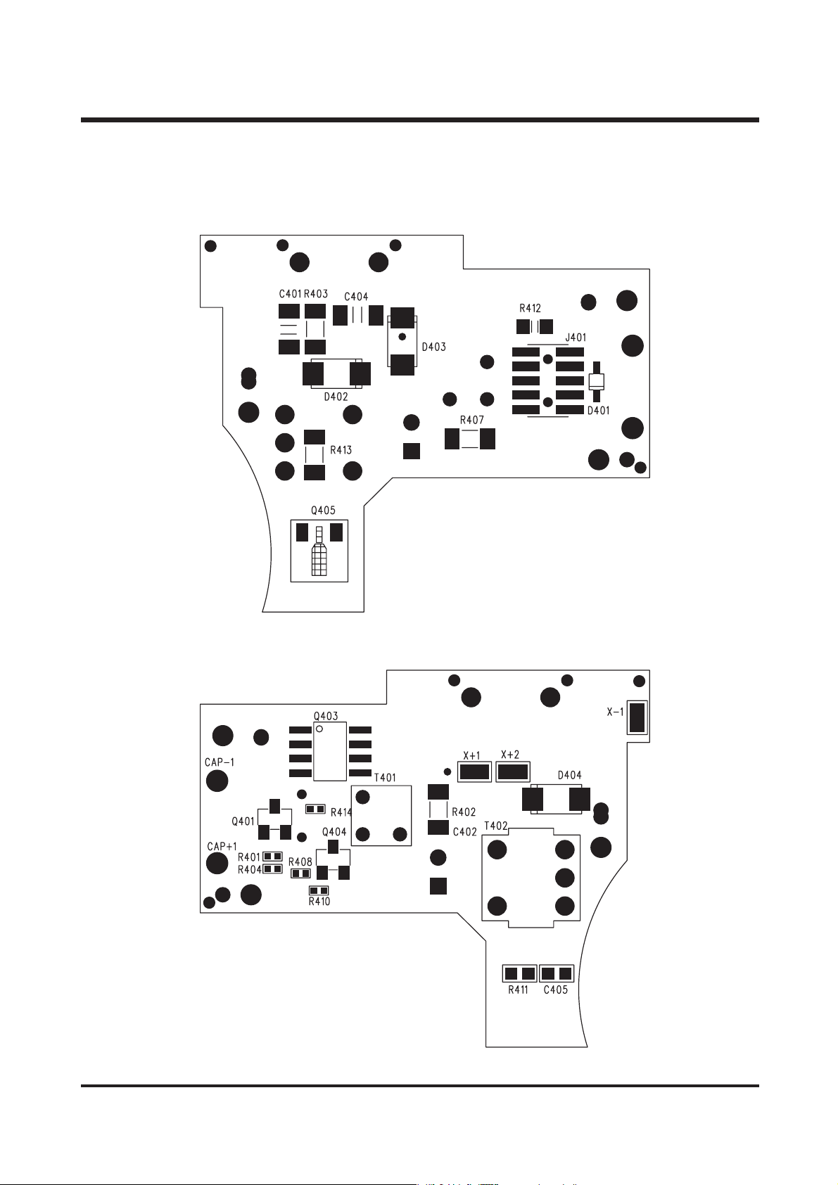
39
4) FLASH
BOARD
Assembly
a) Parts Arrangement
<TOP>
<BOTTOM>
ⅤⅤ.. PPRR OODD UUCC TT CCOONN SSTT RR UU CCTT IIOONN
Page 39
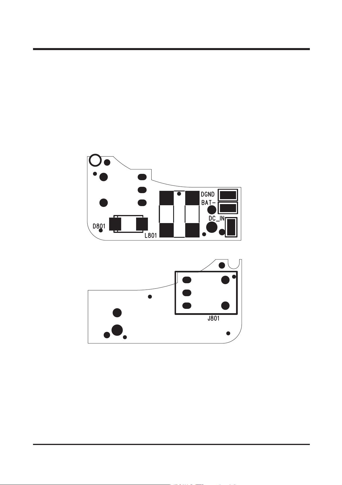
40
ⅤⅤ.. PPRR OODD UUCC TT CCOONN SSTT RR UU CCTT IIOONN
5) JACK
BOARD
Assembly
a) Parts Arrangement
<TOP>
<BOTTOM>
Page 40
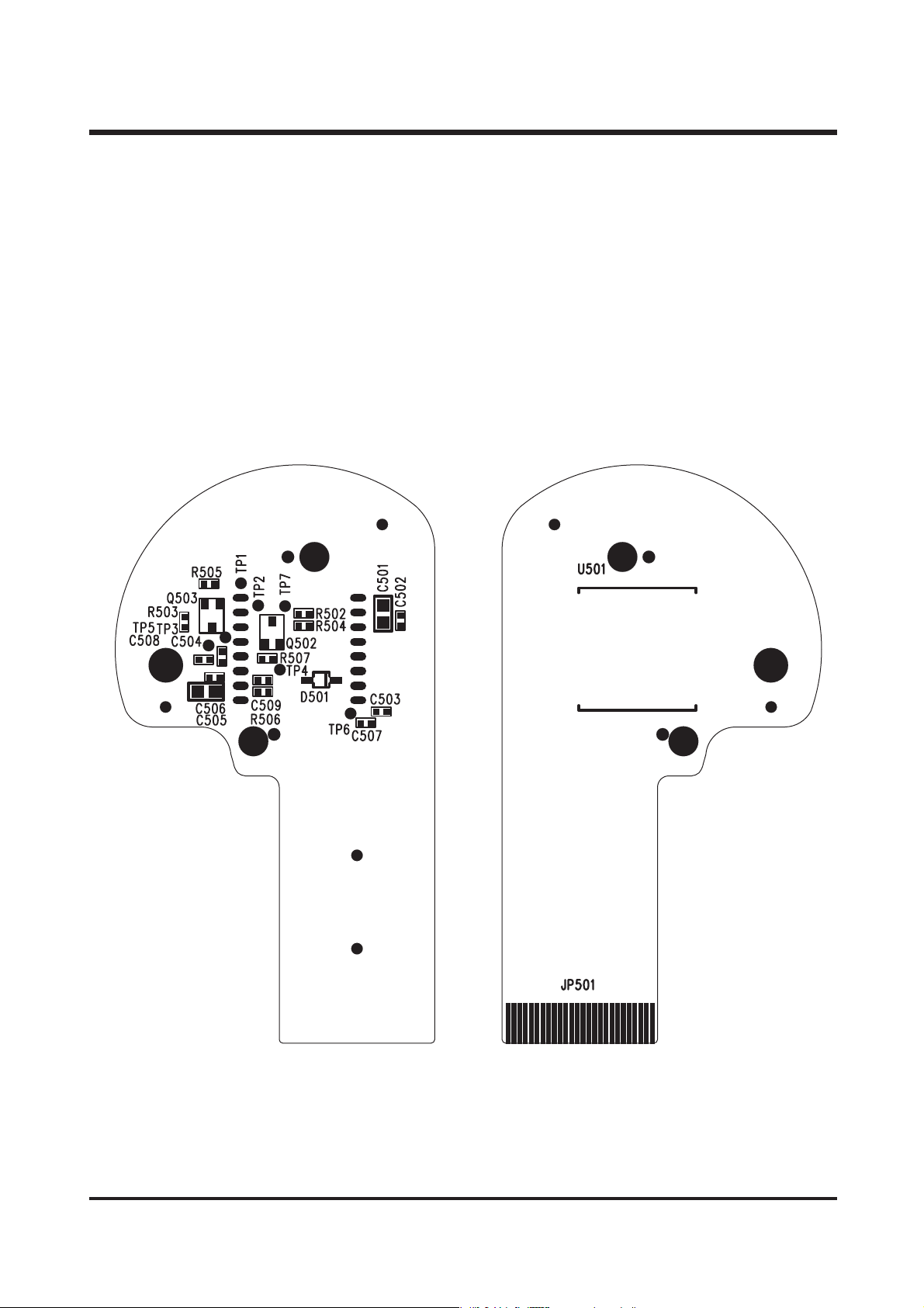
41
ⅤⅤ.. PPRR OODD UUCC TT CCOONN SSTT RR UU CCTT IIOONN
6) CCD
BOARD
Assembly
a) Parts Arrangement
<TOP>
<BOTTOM>
Page 41
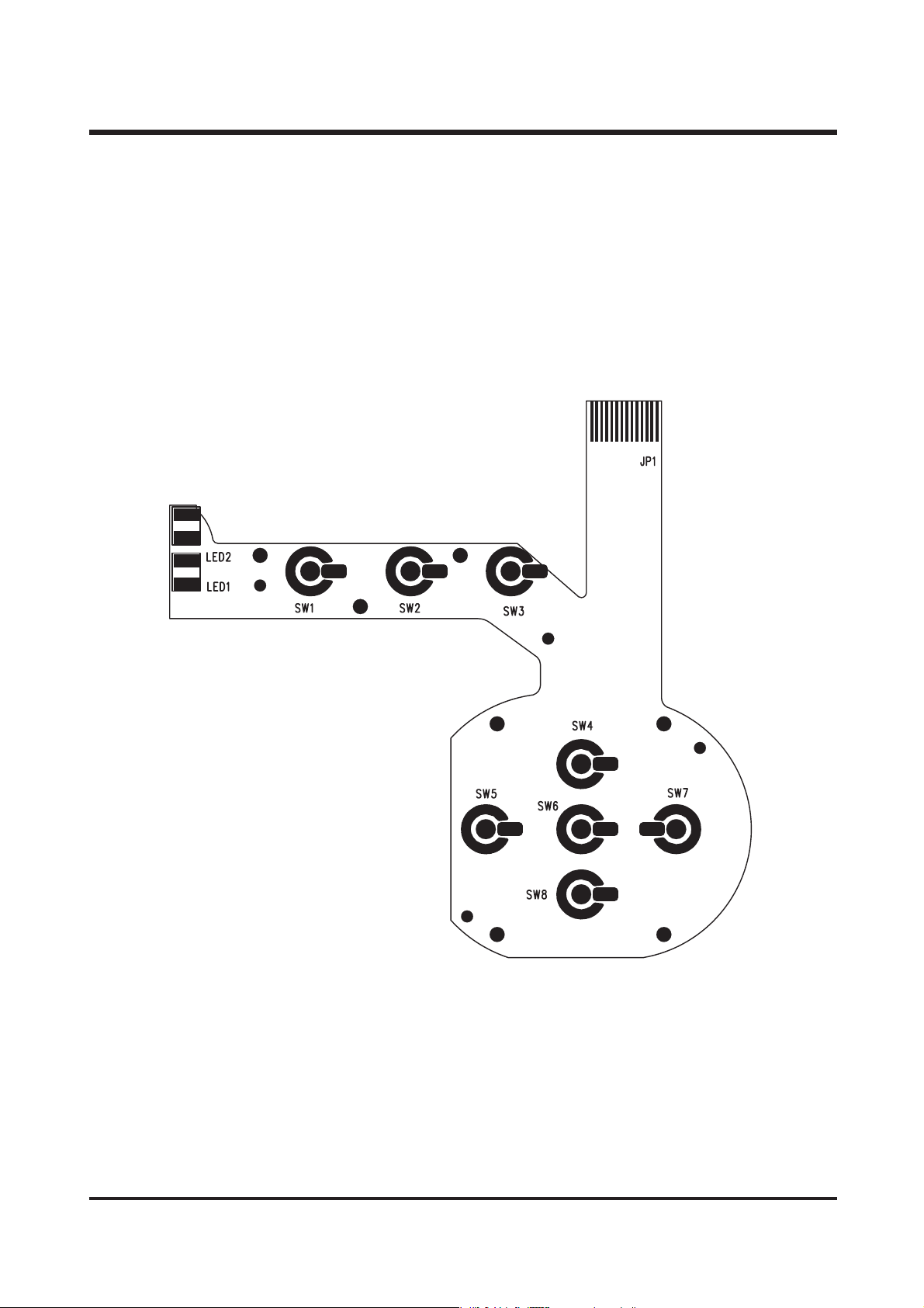
42
ⅤⅤ.. PPRR OODD UUCC TT CCOONN SSTT RR UU CCTT IIOONN
7) SW2
BOARD
Assembly
a) Parts Arrangement
Page 42
43
Ⅵ. TROUBLESHOOTING
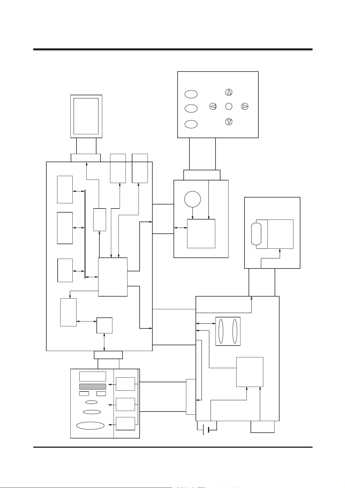
1. BLOCK DIAGRAM
MENU
SDRAM
8Mx16bit
8Mx8bit
NAND FLASH
SEEPROM
256Kx8bit
TFT LCD
FPC
CON
LCD
Driver
CONCON
USB
DSP
VIDEO
CON
FLASH
LCD
S/W
SHUTTER
FPC
CON
SCPU
[SCPU board]
[Switch board]
TUBE
CON
STROBO
[Flash board]
[MCU board]
CDS/TG
Lens module
CCD
VD
CON
FPC
FOCUS
S/H
ZOOM IRIS
MD124
STI152A
STI151A
FPC
CON
CON
2XAA
SD CARD
MB3883
CON
[Power board]
DC-IN 3.3V
Page 43
44
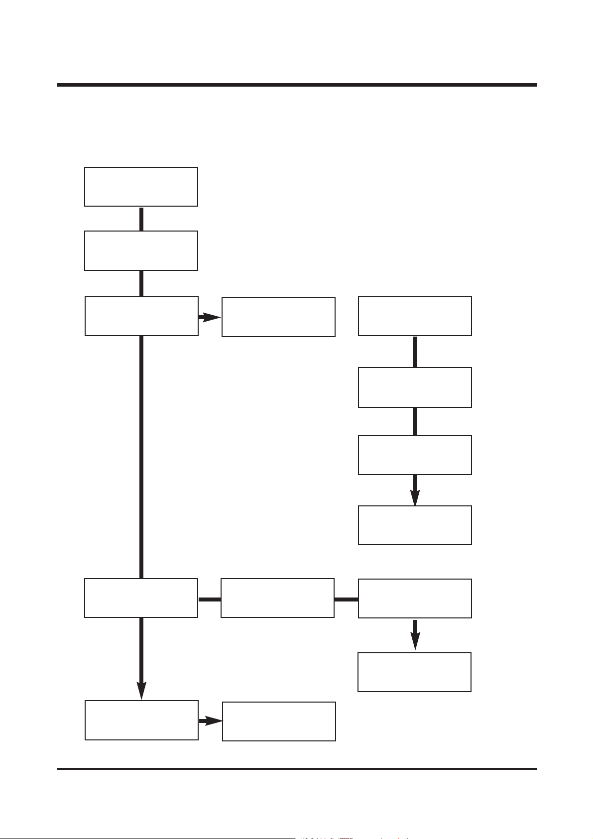
2. Principal troubleshooting.
1) Does not Power on.
Check : Power input
(Battery, Adaptor, etc.)
Check the connecting
state the JP802
Check : Connectors to
each PCB
(Dirt,Short,Solder, etc.)
Camera doesn't power
on with batteries and
AC adaptor
Camera off automaticaly
Check F801 fuse
condition
(Both ends : 0Ω)
Check : D807,Q303
Check parts : U801,
Q801, Q802, Q803, Q804,
Q806, Q808, Q811, Q816
Check parts : L801,
L802, L803, L804, L806,
L807, L808
Check : U1, U5, U6, U7
Check the power
button.
Check : C844
Camera malfunction
Check the connecting
state : JP1, JP2
ⅥⅥ.. TT RROO UUBBLL EE SSHH OO OO TT IINNGG
Page 44
45
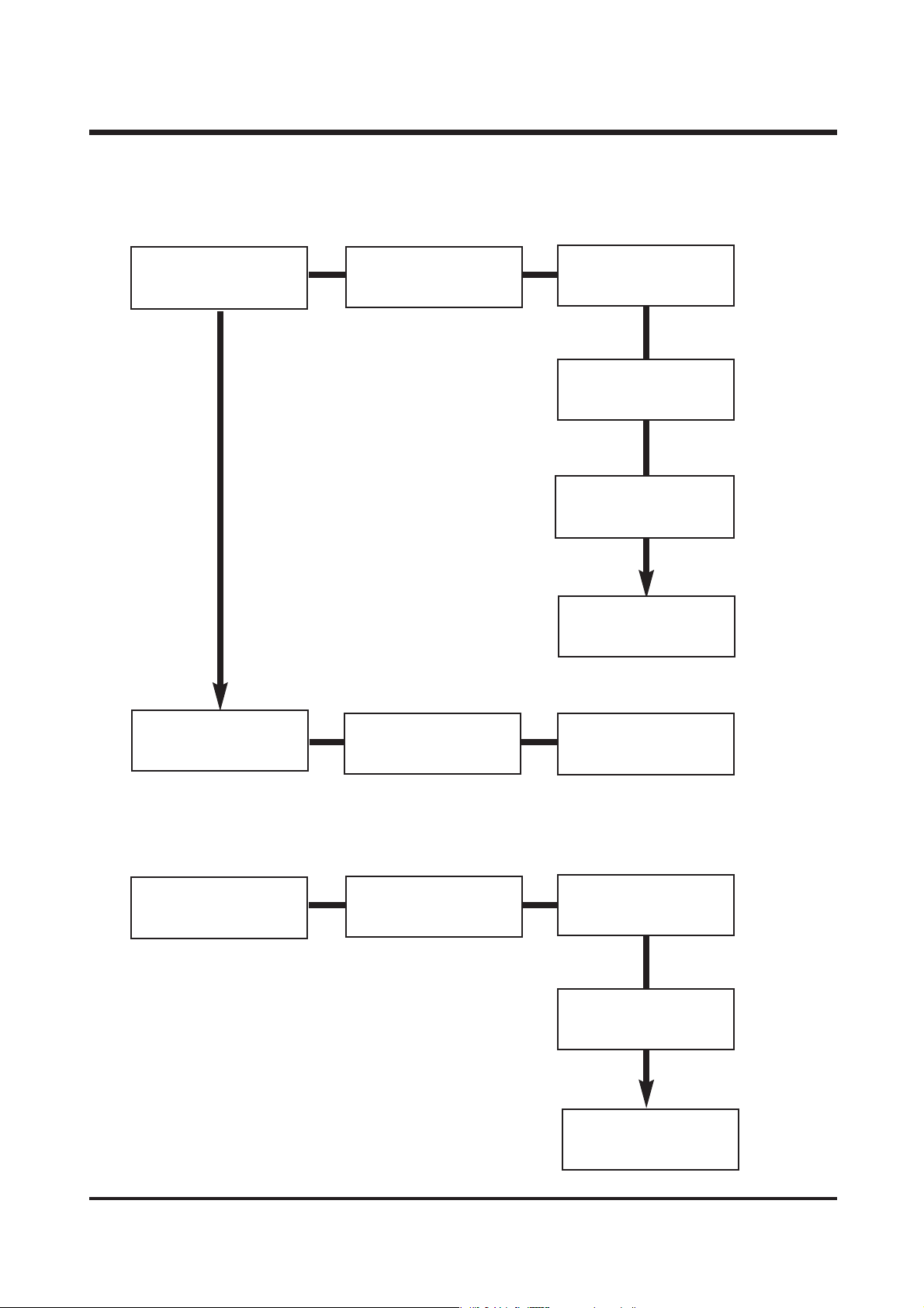
2) STROBO relation defect.
3) TFT LCD display defect.
Charge defect
Check the connecting
state : JP2, JP802
Flash doesn't fire
Check : Connectors to
each PCB
(Dirt,Short,Solder, etc.)
Check :
U806, Q821, D810, Q822
Check parts :
D402, D403
Check parts :
C844, R305, T401
Check the connecting
state :
JP2, JP802, JP401
Check :
D401, D404,
Q401, Q403, T402
TFT LCD display defect
Check :
Q3, Q4, Q5, U5
Check : Connectors to
each PCB
(Dirt,Short,Solder, etc.)
Check the connecting
state :
JP5, JP6
Check :
TFT LCD, CCD
ⅥⅥ.. TT RROO UUBBLL EE SSHH OO OO TT IINNGG
Page 45
46
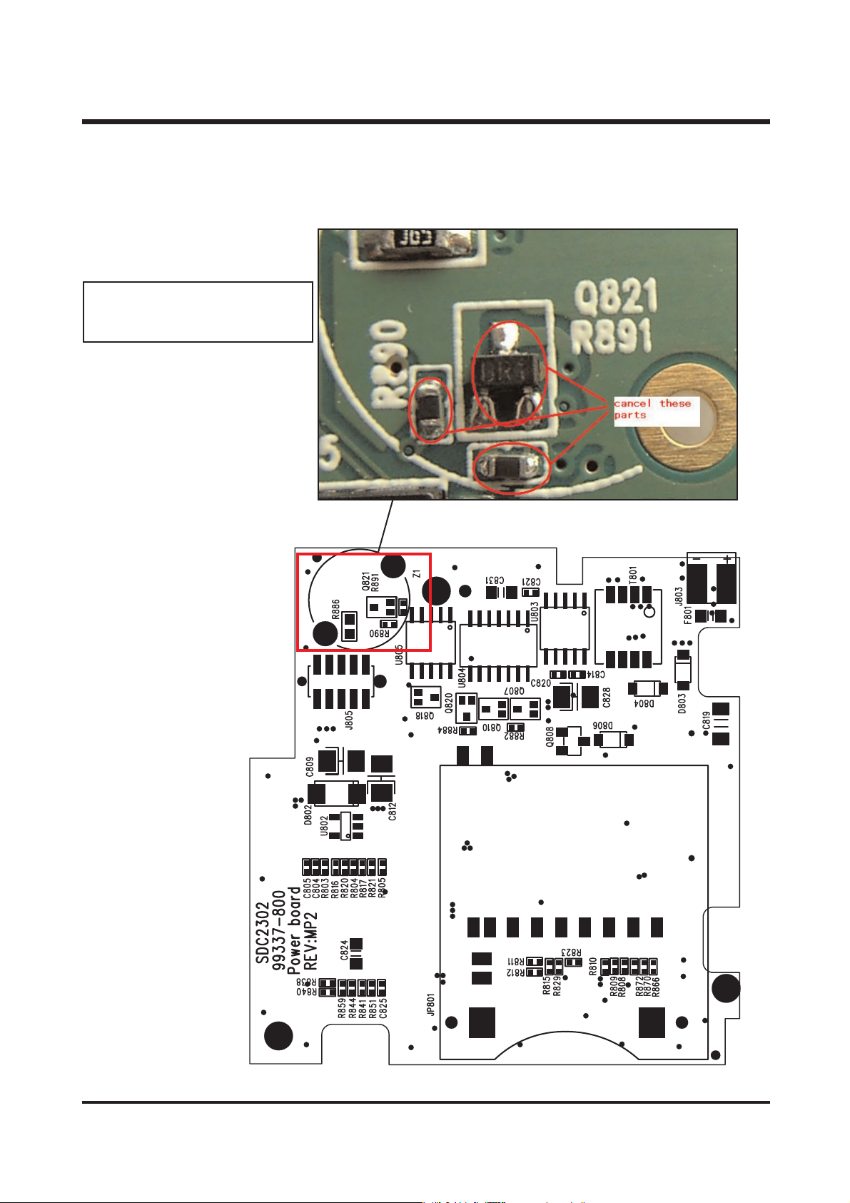
3. PARTS MODIFICATION
1) POWER BOARD ASSEMBLY (TOP)
LOW BATTERY lights on with it's
power on
- Deleted the R890, R891, Q821
ⅥⅥ.. TT RROO UUBBLL EE SSHH OO OO TT IINNGG
Page 46
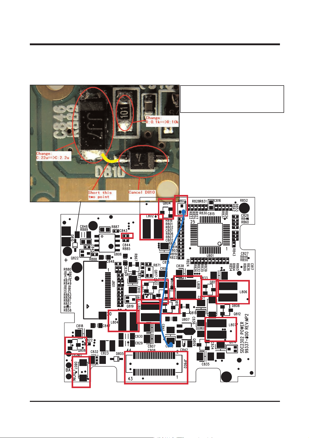
47
2) POWER BOARD ASSEMBLY (BOTTOM)
LOW BATTERY lights on with it's power on
- C846 : change from 22u to 2.2u
- R889 : change from 0.1Kto 10K
- D810 : short with C846 after delete
ⅥⅥ.. TT RROO UUBBLL EE SSHH OO OO TT IINNGG
Page 47
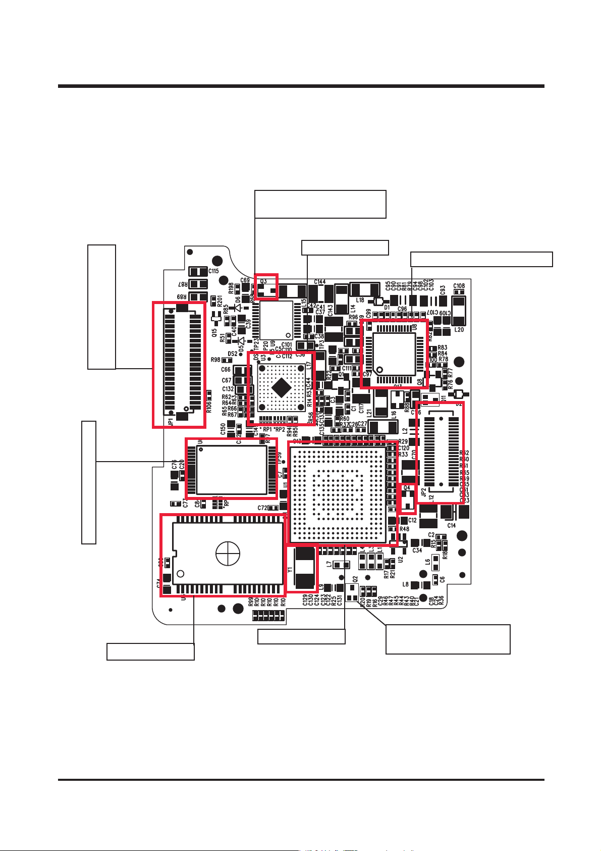
4. PARTS EXPLANTION OF EACH BOARD
1) MCU BOARD ASSEMBLY (TOP)
48
LCD display default
- Q3, Q4
UU 11 :: DDSS PP
UU 55 :: MMEEMM OORRYY
UU 66 :: FFLL AASS HH RR OOMM
UU88 :: TTFFTT LLCCDD CCOONN TTRROOLL
UU 33 :: AAGGCC
Automatic power off
- check condition of jP1
USB transmission default
- Q2
ⅥⅥ.. TT RROO UUBBLL EE SSHH OO OO TT IINNGG
Page 48
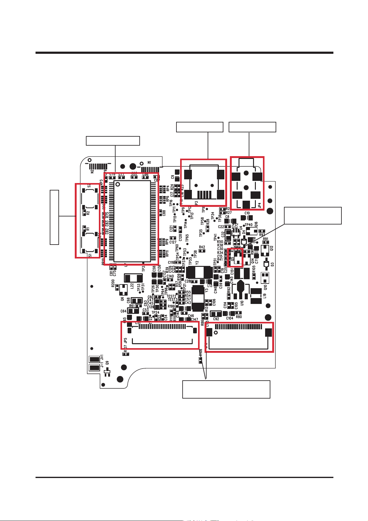
49
LCD display default
- check condition of JP5, JP6
LCD display default
- Q5
ZOOM SWITCH
USB JACK
A/V JACK
UU 77 :: SSDDRR AA MM
2) MCU BOARD ASSEMBLY (BOTTOM)
ⅥⅥ.. TT RROO UUBBLL EE SSHH OO OO TT IINNGG
Page 49
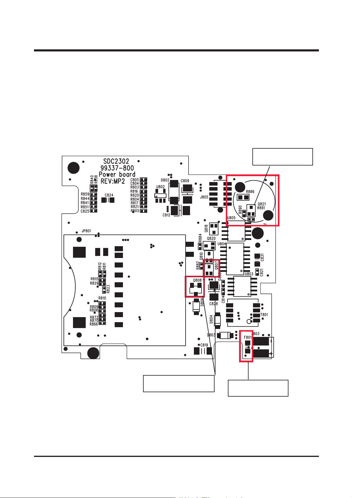
50
Deosn't POWER ON
- F801 (FUSE)
Flash doesn't fire
- Q821
Camera malfunction
- Q807, Q808
3) POWER BOARD ASSEMBLY (TOP)
ⅥⅥ.. TT RROO UUBBLL EE SSHH OO OO TT IINNGG
Page 50
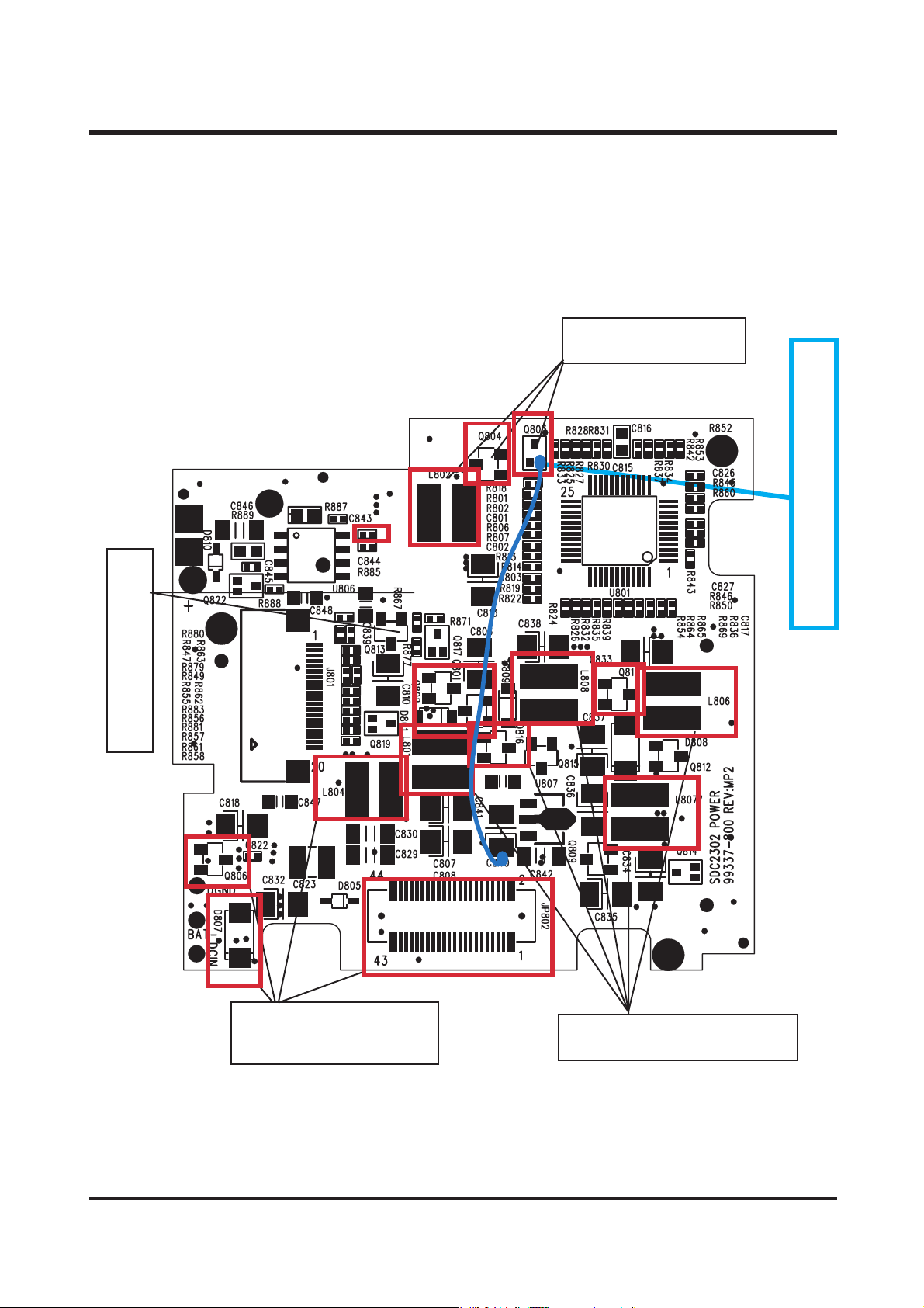
51
Camera malfunction
- L806, L807, L801, Q816, L808
Camera malfunction
- Q803, Q804, L802
Camera malfunction
- Q804, D807, L804
- check condition of JP 802
Camera malfunction
- Q801, Q802, D801
Just red led on, and operation default.
- connect Q803 and C840.
4) POWER BOARD ASSEMBLY (BOTTOM)
ⅥⅥ.. TT RROO UUBBLL EE SSHH OO OO TT IINNGG
Page 51
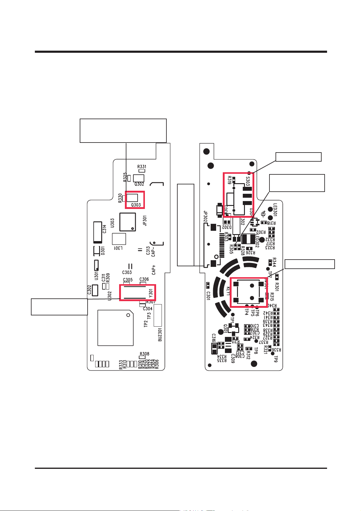
52
Camera malfunction
- check Y301
POWER SWITCH
RELEASE SWITCH
Working with battery, but not
AC adapter
- change Q303
Automatic power OFF
- Check condition of JP302
Flash doesn't fire
- R305
5) SW1 BOARD ASSEMBLY
(TOP) (BOTTOM)
ⅥⅥ.. TT RROO UUBBLL EE SSHH OO OO TT IINNGG
Page 52
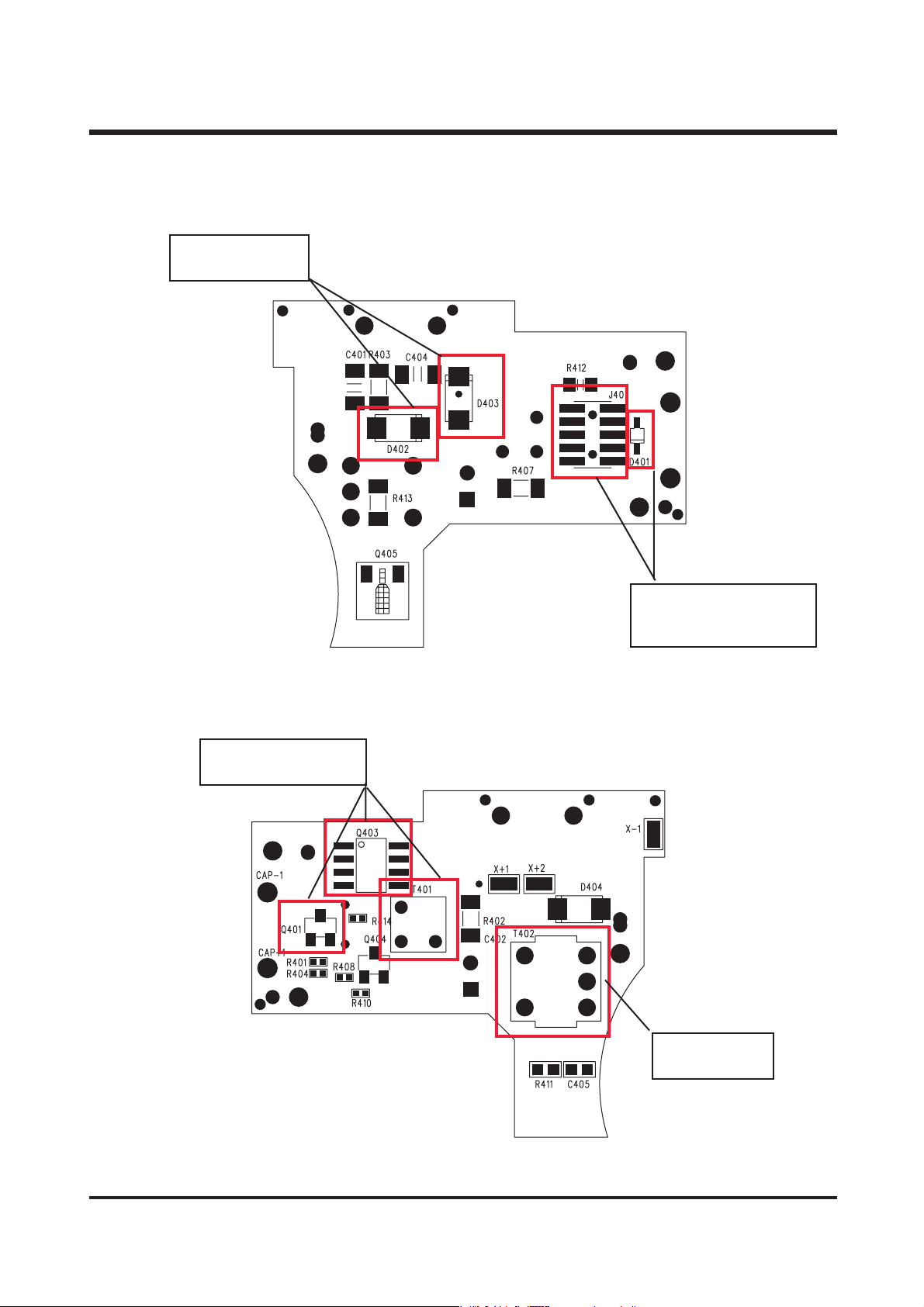
53
Flash doesn't fire
- Q401, Q403, T401
Charge default
- D402, D403
Charge default
- T402
Flash doesn't fire
- D401
- check conditionof J401
6) FLASH BOARD ASSEMBLY
(TOP)
(BOTTOM)
ⅥⅥ.. TT RROO UUBBLL EE SSHH OO OO TT IINNGG
Page 53
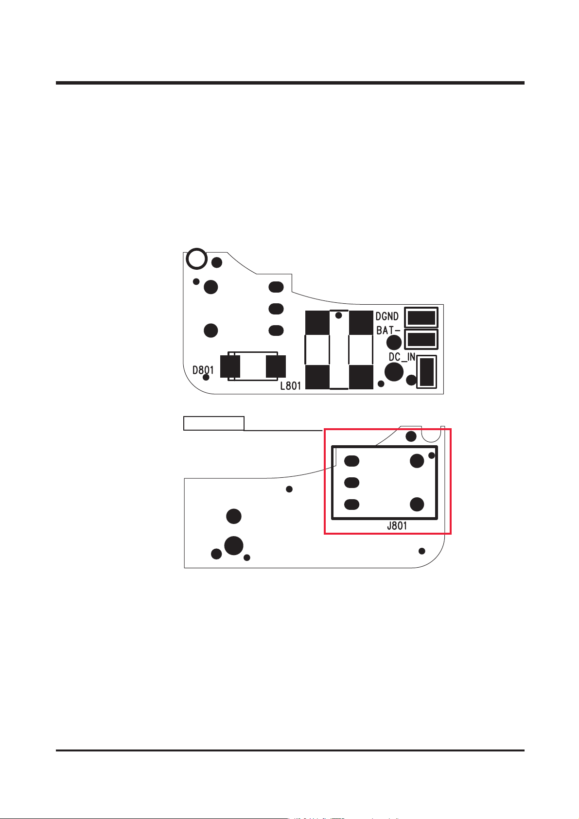
54
DC JACK
7) JACK BOARD ASSEMBLY
ⅥⅥ.. TT RROO UUBBLL EE SSHH OO OO TT IINNGG
Page 54
55
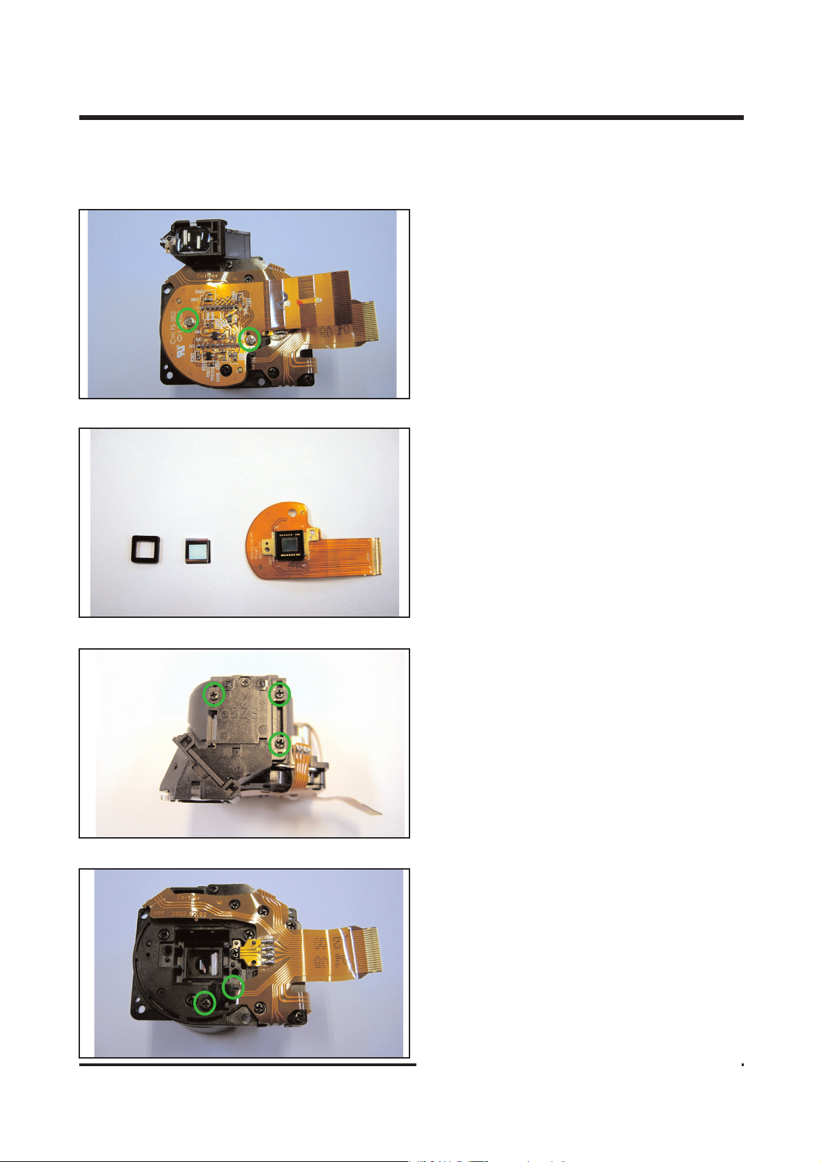
5. DISASSEMBLE THE BARREL ASS'Y
1. Remove the 2 screws.
2. Remove the CCD F PCB ASS'Y, OLPF and OLPF
Cusion.
3. Remove the 3 screws and thke off the finder
ass'y
4. Resoldering the shutter f pcb and remove the
screw.
ⅥⅥ.. TT RROO UUBBLL EE SSHH OO OO TT IINNGG
Page 55
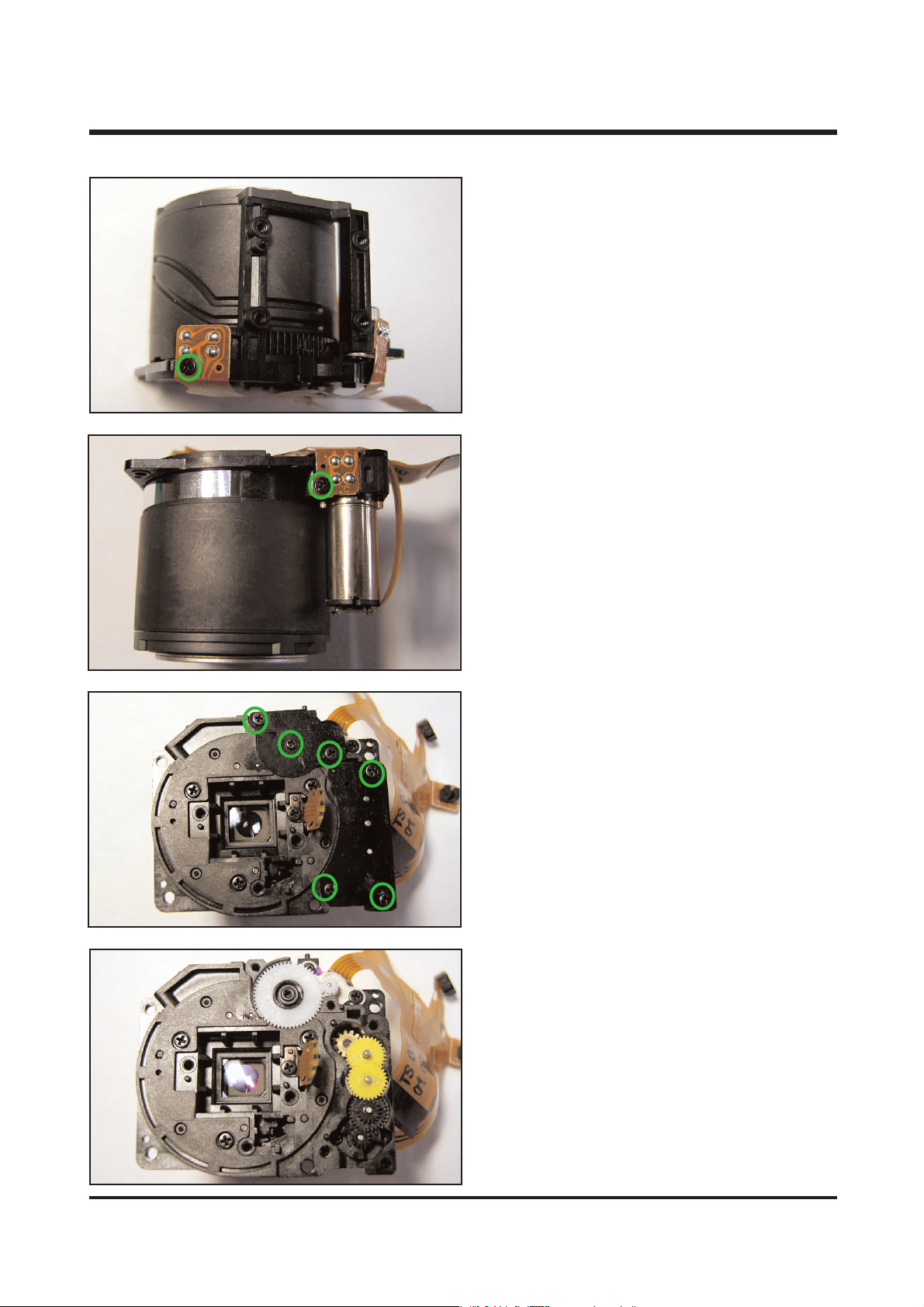
56
5. Remove the screw.
6. Remove the screw.
7. Remove the 6 screws.
8. You can see the gears.
ⅥⅥ.. TT RROO UUBBLL EE SSHH OO OO TT IINNGG
Page 56
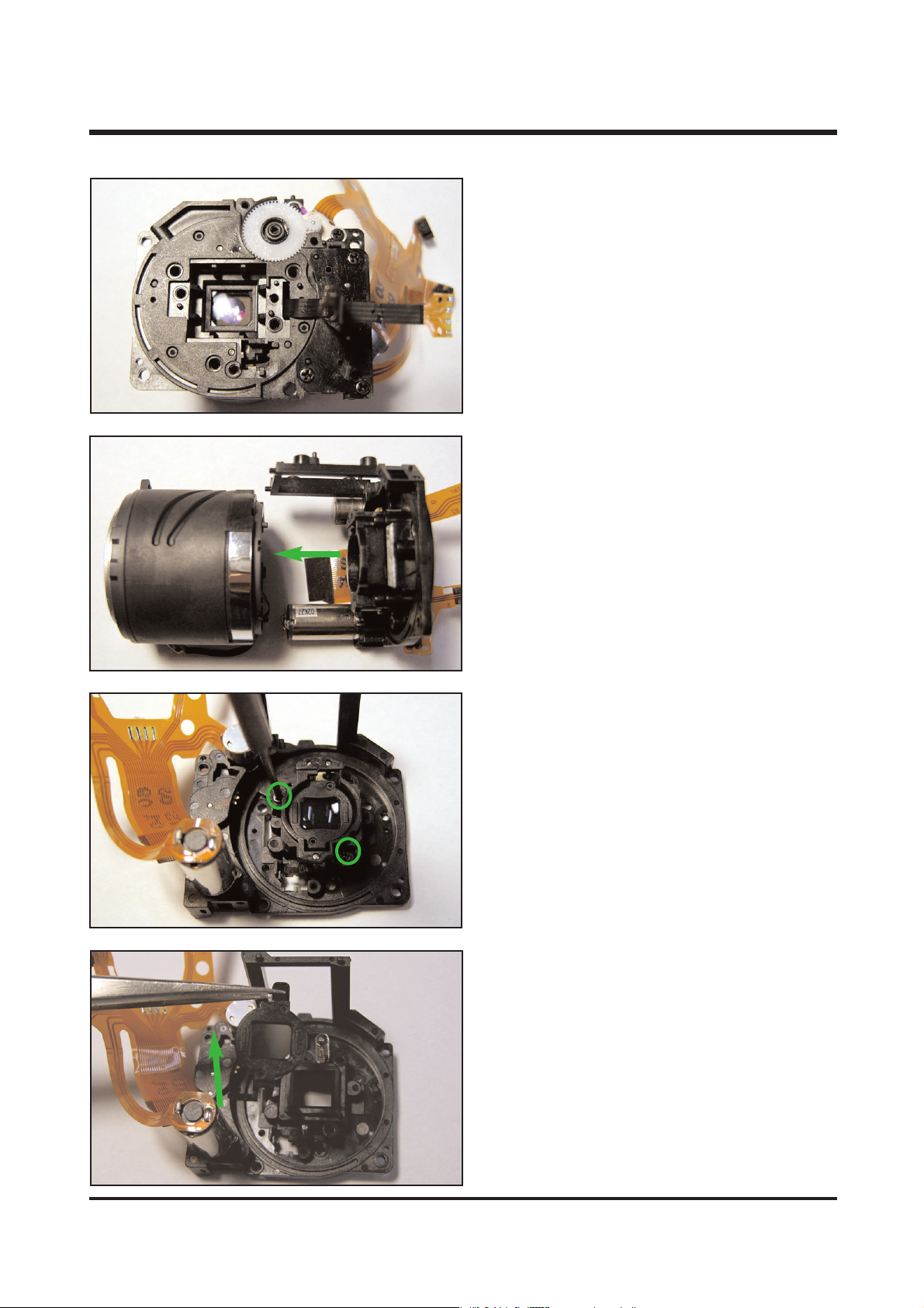
57
9. Remove the F PCB Guide.
10. Seperat the Lens base ass'y and Guide
barrel ass'y.
11. Remove the 2 screws.
12. Remove the AF holder.
ⅥⅥ.. TT RROO UUBBLL EE SSHH OO OO TT IINNGG
Page 57
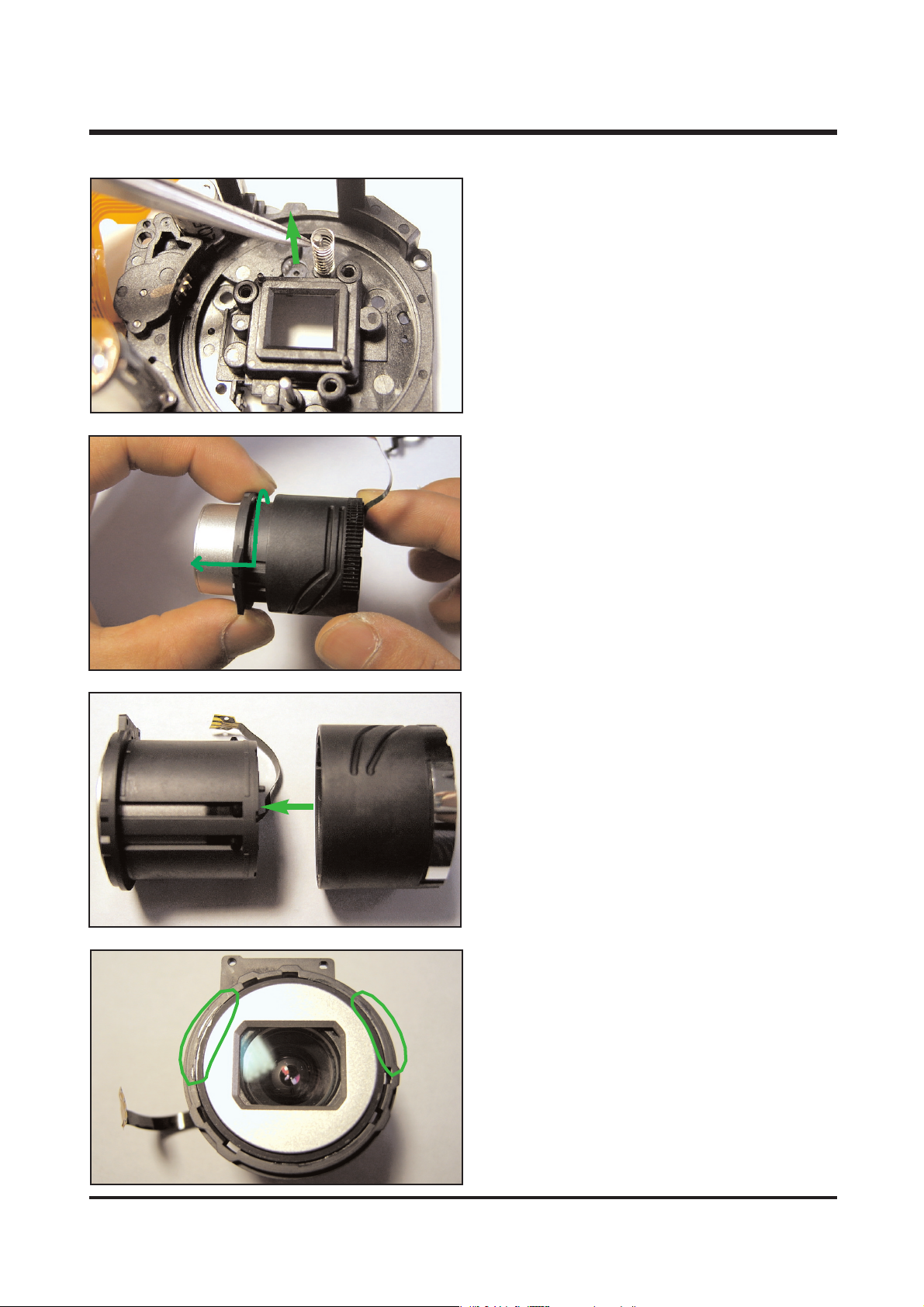
58
13. Remove the spring.
14. Rotate the Cam barrel ass'y in the direction
of the arrow and then remove it from Guide
barrel ass'y.
15. Remove the Cam barrel ass'y.
16. Unglue the 2 parts as direction of figure.
ⅥⅥ.. TT RROO UUBBLL EE SSHH OO OO TT IINNGG
Page 58
59
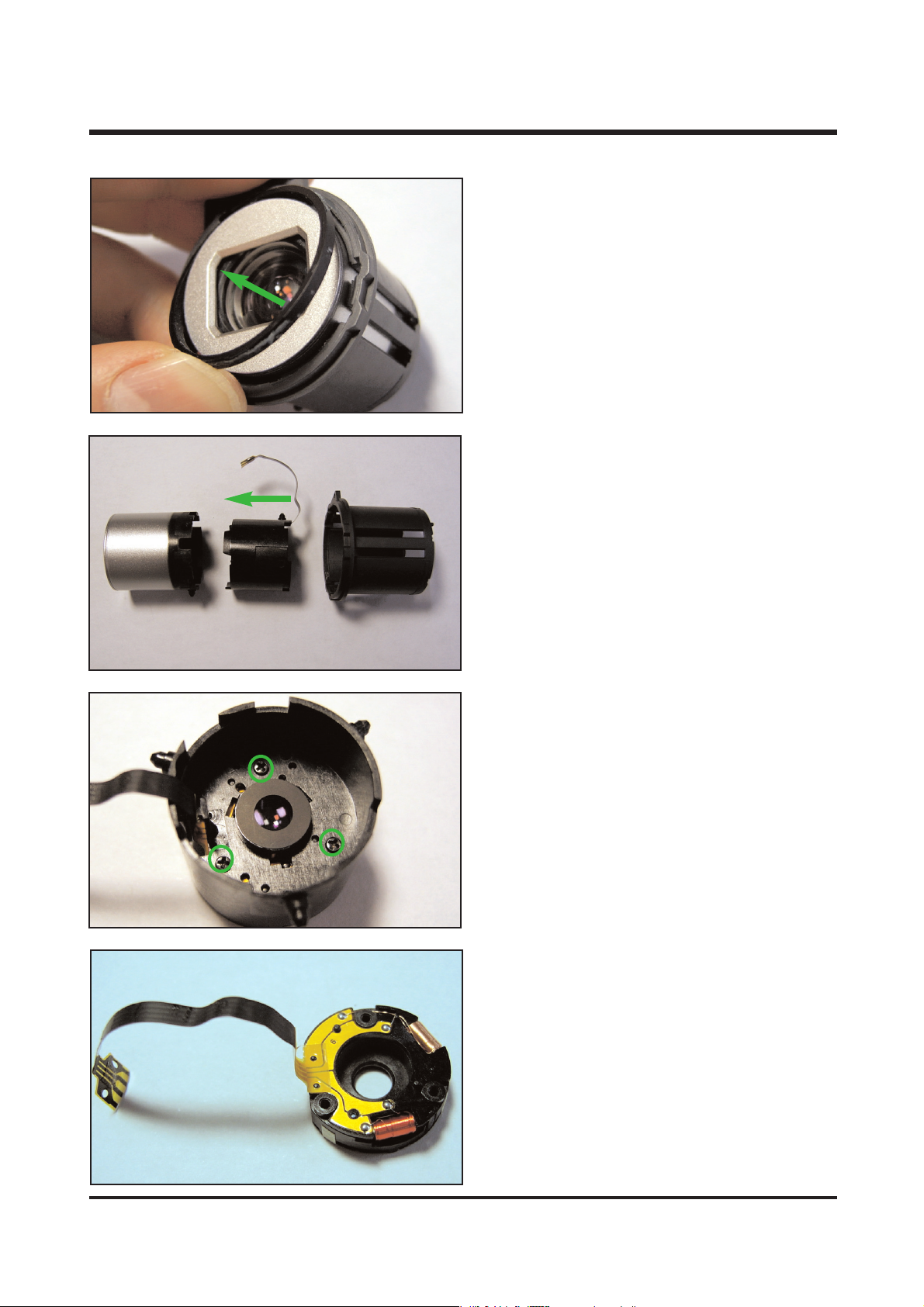
17. Remove the Outer barrel ring.
18. Remove the zoomring, 2nd barrel ass'y and
Cam barrel
19. Remove the 3 screws.
20. You can see the Shutter ass'y
ⅥⅥ.. TT RROO UUBBLL EE SSHH OO OO TT IINNGG
Page 59
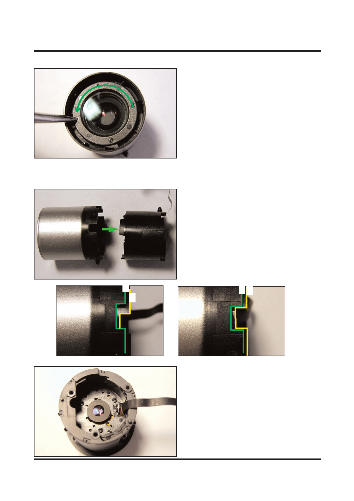
60
21. Rotate the 1st lens ass'y in the direction
of the arrow and then remove the Front lens
ass'y
1. Assemble the 2nd barrel ass'y into the
Zoomring
※ Align line X of Zoomring with line Y of the
6. ASSEMBLE THE BARREL ASS'Y
XX
YY
XX
YY
2. Assemble the Zoomring ass'y into the Cam
barrel
※ After assembled, Located the shutter f pcb as
left figure.
ⅥⅥ.. TT RROO UUBBLL EE SSHH OO OO TT IINNGG
Page 60
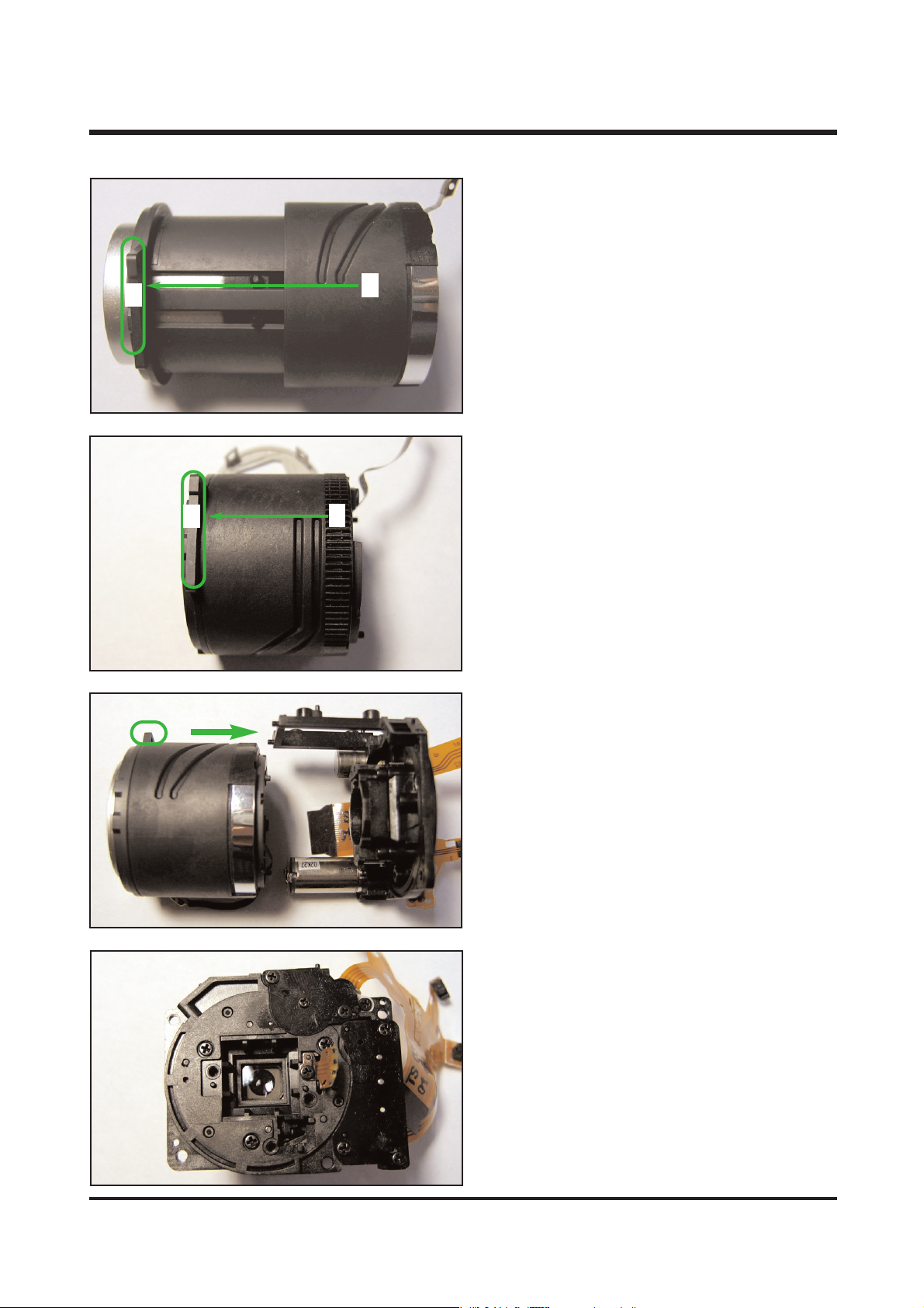
61
3. Assemble the Came barrel ass'y into the Guide
barrel.
※ Align line X of Guide barrel with Y.
4. After assembled, the part Y is located the
line X.
5. Assemble the Guide barrel ass'y into the
Lens base ass'y.
6. Tighten the screws.
XX
YY
XX
YY
ⅥⅥ.. TT RROO UUBBLL EE SSHH OO OO TT IINNGG
 Loading...