

Ver.
L TE eNB
System Description

COPYRIGHT
This manual is proprietary to SAMSUNG Electronics Co., Ltd. and is protected by copyright.
No information contained herein may be copied, translated, transcribed or duplicated for any commercial
purposes or disclosed to the third party in any form without the prior written consent of SAMSUNG Electronics
Co., Ltd.
TRADEMARKS
Product names mentioned in this manual may be trademarks and/or registered trademarks of their respec tive
companies.
This manual should be read and used as a guideline for properly installing and operating the product.
This manual may be changed for the system improvement, standardization and other technical reasons without prior
notice.
If you need updated manuals or have an y questions concerning the contents of the manuals, contact our Document
Center at the following address or Web site:
Address: Document Center 3rd Floor Jeong-bo-tong-sin-dong. Dong-Suwon P.O. Box 105, 416, Maetan-3dong
Yeongtong-gu, Suwon-si, Gyeonggi-do, Korea 442-600
Homepage: http://www.samsungdocs.com
©2011 SAMSUNG Electronics Co., Ltd. All rights reserved.

INTRODUCTION
Purpose
This manual describes the features, functions and configuration of LTE eNB.
Content and Organization
This manual consists of five Chapters and Abbreviations.
LTE eNB System Description
CHAPTER 1. Overview of Samsung LTE System
Introduction to Samsung LTE System
Network Configurations of Samsung LTE Network
Functional Architecture of Samsung LTE
CHAPTER 2. Overview of LTE eNB
Introduction to LTE eNB
Key Functions
Specifications
System-to-System Interfaces
CHAPTER 3. LTE eNB Architecture
Hardware Architecture
Software Architecture
CHAPTER 4. Message Flows
Call processing Message Flow
Data Message Flow
Network Synchronization Flow
Alarm Signal Flow
Loading Flow
Operation/Maintenance Message Flow
© SAMSUNG Electronics Co., Ltd. I
INTRODUCTION
CHAPTER 5. Supplementary Functions and Tools
Web-EMT
About CLI
ABBREVIATIONS
Provides explanations of the abbreviations used throughout this manual.
Conventions
The following symbols are used in this manual. The following types of paragraphs contain
special information that must be carefully read and thoroughly understood.
NOTE
This provides references for additional information.
Revision History
EDITION DATE OF ISSUE REMARKS
1.0 06. 2011. First Edition
II
© SAMSUNG Electronics Co., Ltd.

LTE eNB System Description
TABLE OF CONTENTS
INTRODUCTION I
Purpose....................................................................................................................................... I
Content and Organization............................................................................................................ I
Conventions................................................................................................................................II
Revision History.......................................................................................................................... II
CHAPTER 1. Overview of Samsung LTE System 1-1
1.1 Introduction to Samsung LTE System................................................................................. 1-1
1.2 Samsung LTE Network Configuration.................................................................................. 1-2
1.3 LTE System Functional Architecture....................................................................................1-4
CHAPTER 2. Overview of LTE eNB 2-1
2.1 Introduction to LTE eNB........................................................................................................ 2-1
2.2 Key Functions........................................................................................................................ 2-7
2.2.1 Physical layer processing ........................................................................................... 2-7
2.2.2 Call Processing......................................................................................................... 2-10
2.2.3 IP Processing............................................................................................................ 2-12
2.2.4 SON.......................................................................................................................... 2-13
2.2.5 Convenient Operation and Maintenance .................................................................. 2-14
2.3 Specifications ...................................................................................................................... 2-16
2.4 System-to-System Interface................................................................................................ 2-18
2.4.1 Interface Architecture................................................................................................ 2-18
2.4.2 Protocol Stack........................................................................................................... 2-19
CHAPTER 3. LTE eNB Architecture 3-1
3.1 Hardware Architecture .......................................................................................................... 3-1
3.1.1 UADU ......................................................................................................................... 3-4
3.1.2 L8HU .......................................................................................................................... 3-6
3.1.3 Power supply .............................................................................................................. 3-8
3.1.4 Environmental Devices............................................................................................. 3-10
© SAMSUNG Electronics Co., Ltd. III

TABLE OF CONTENTS
3.1.5 External Interface ......................................................................................................3-13
3.2 Software Architecture ..........................................................................................................3-15
3.2.1 Basic Software Architecture.......................................................................................3-15
3.2.2 CPS Block................................................................................................................. 3-18
3.2.3 OAM Blocks...............................................................................................................3-21
CHAPTER 4. Message Flows 4-1
4.1 Call-Processing Message Flows...........................................................................................4-1
4.2 Data Message Flow ..............................................................................................................4-21
4.3 Network Synchronization Flow...........................................................................................4-22
4.4 Alarm Signal Flow................................................................................................................4-23
4.5 Loading Flow........................................................................................................................4-24
4.6 Operation and Maintenance Message Flow .......................................................................4-25
CHAPTER 5. Supplementary Functions and Tools 5-1
5.1 Web-EMT.................................................................................................................................5-1
5.2 CLI ...........................................................................................................................................5-2
ABBREVIATION I
A ~ C ..........................................................................................................................................I
D ~ G .........................................................................................................................................II
H ~ M ........................................................................................................................................III
N ~ Q ....................................................................................................................................... IV
R ~ T ........................................................................................................................................ V
U ~ W ....................................................................................................................................... VI
IV
© SAMSUNG Electronics Co., Ltd.

LTE eNB System Description/Ver.1.0
LIST OF FIGURES
Figure 1.1 Samsung LTE Network Configurations.................................................................. 1-2
Figure 1.2 Functions of E-UTRAN and EPC........................................................................... 1-4
Figure 2.1 Indoor eNB + L8HU Installation............................................................................. 2-2
Figure 2.2 Outdoor eNB + L8HU Installation.......................................................................... 2-3
Figure 2.3 LTE eNB System Interface Architecture .............................................................. 2-18
Figure 2.4 UE eNB Protocol Stack ....................................................................................... 2-19
Figure 2.5 eNB S-GW User Plane Protocol Stacks..........................................................2-20
Figure 2.6 eNB MME Control Plane Protocol Stacks....................................................... 2-20
Figure 2.7 eNB eNB User Plane Protocol Stacks........................................................... 2-21
Figure 2.8 eNB eNB Control Plane Protocol Stacks ........................................................ 2-21
Figure 2.9 eNB LSM Interface Protocol Stacks............................................................... 2-22
Figure 3.1 Removable eNB’s Internal Configuration .............................................................. 3-2
Figure 3.2 Outdoor eNB Configuration ................................................................................... 3-3
Figure 3.3 Configuration......................................................................................................... 3-4
Figure 3.4 L8HU Configuration............................................................................................... 3-6
Figure 3.5 Power Supply........................................................................................................ 3-8
Figure 3.6 Power Diagram ..................................................................................................... 3-9
Figure 3.7 Outdoor eNB’s Heat Discharge ........................................................................... 3-10
Figure 3.8 UADU Heat-Discharge Mechani sm......................................................................3-11
Figure 3.9 Sensors............................................................................................................... 3-12
Figure 3.10 UADU External Interface................................................................................... 3-13
Figure 3.11 L8HU External Interface .................................................................................... 3-14
Figure 3.12 eNB Software Architecture ................................................................................ 3-15
Figure 3.13 CPS Architecture ...............................................................................................3-18
Figure 4.1 Attach Process...................................................................................................... 4-2
Figure 4.2 Service Request Process by UE ........................................................................... 4-4
Figure 4.3 Service Request Process by Networking .............................................................. 4-5
Figure 4.4 Detach Process by UE .......................................................................................... 4-6
Figure 4.5 Detach Process by MME....................................................................................... 4-8
Figure 4.6 X2-based Handover Process ................................................................................ 4-9
Figure 4.7 S1-based Handover Process ...............................................................................4-11
Figure 4.8 E-UTRAN-UTRAN PS Handover Process........................................................... 4-14
Figure 4.9 UTRAN-E-UTRAN PS Handover Process........................................................... 4-16
Figure 4.10 CS Fallback to UTRAN Process (UE in Active Mode, No PS HO Support)....... 4-18
Figure 4.11 CS Fallback to GERAN Process (UE in Active Mode, No PS HO Support)....... 4-19
© SAMSUNG Electronics Co., Ltd. V

TABLE OF CONTENTS
Figure 4.12 eNB System Control and Traffic Flow................................................................4-21
Figure 4.13 eNB Network Synchronization Flow...................................................................4-22
Figure 4.14 eNB System Alarm Flow....................................................................................4-23
Figure 4.15 Loading Signal Flow...........................................................................................4-24
Figure 4.16 Operation and Maintenance Signal Flow ...........................................................4-25
Figure 5.1 Web-EMT Interface ................................................................................................5-1
VI
© SAMSUNG Electronics Co., Ltd.

LTE eNB System Description
CHAPTER 1. Overview of Samsung
LTE System
1.1 Introduction to Samsung LTE System
The Samsung LTE system is a wireless network system supporting 3GPP Long Term
Evolution (3GPP LTE; hereafter, LTE) based services. It improved the disadvantages of
low transmission speed and the high cost of the data services provided by the existing
3GPP mobile communication system. The Samsung LTE system is a next generation
wireless network system that can provide high-speed data services at a low cost regardless
of time and location.
The Samsung LTE system supports the downlink Orthogonal Frequency Division Multiple
Access (OFDMA) transmission technology and the uplink Single Carrier (SC) FDMA
transmission technology in Frequency Division Duplex (FDD) mode, and supports a
scalable bandwidth for supporting various spectrum allocations to provide high-speed data
services. In addition, system performance and capacity have increased as a result of highperformance hardware; the Samsung LTE system can easily accommodate a variety of
functions and services.
The Samsung LTE system consists of the evolved UTRAN Node B (eNB), Evolved Packet
Core (EPC), and LTE System Manager (LSM). The eNB is a system between the UE and
EPC, and processes packet calls by connecting to the User Equipment (UE) wirelessly in
accordance with the LTE Air standards. The EPC is between the eNB and the Packet Data
Network (PDN), and performs various control functions. The EPC consists of the Mobility
Management Entity (MME), the Serving Gateway (S-GW), and PDN Gateway (P-GW).
The LSM also provides an interface with an operator, functions to manage software,
configurations, performance, and failures as well as an ability to act as a Self-Organizing
Network (SON) server.
Supported System Specifications
The Samsung LTE system is based on the Rel-8 and Rel-9 standards of the LTE
3rd Generation Partnership Project (3GPP).
© SAMSUNG Electronics Co., Ltd. 1-1
CHAPTER 1. Overview of Samsung LTE System
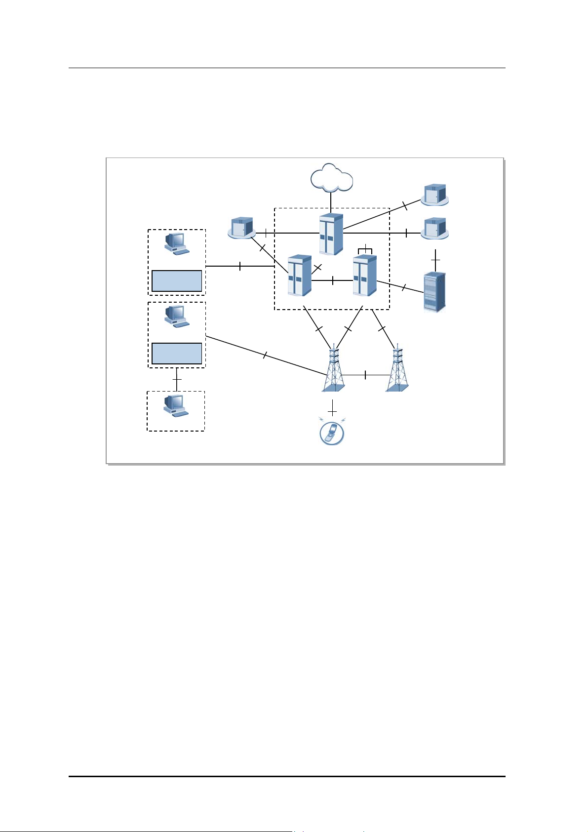
1.2 Samsung LTE Network Configuration
The Samsung LTE system consists of eNB, LSM, and EPC (MME, S-GW, P-GW), and its
network configurations are shown below.
PDN
Gy
EPC
Gz
Gx
OCS
Uu
S10
MME S-GW
S1MME
X2-C
X2-U
S1
PCRF
Sp
S6a
HSS
EMS
ESM
EMS
LSM
MSS
RMI
OFCS
Gz
TL1
SNMP/FTP/UDP
P-GW
S5/S8
S11
S1-U
eNB eNB
UE
Figure 1.1 Samsung L TE Ne t work Conf igur ations
evolved UTRAN Node-B (eNB)
The eNB is located betwee
n the UE and EPC. It processes packet calls by connecting to the
UE wirelessly according to the LTE Air standard. The eNB performs functionalities such as
transmission and receipt of wireless signals, modulation and demodulation of packet traffic
signals, packet scheduling for efficient utilization of wireless resources, Hybrid Automatic
Repeat Request (HARQ)/ARQ processing, Packet Data Convergence Protocol (PDCP) for
packet header compression, and wireless resources control.
It also performs handovers interoperating with the EPC.
Evolved Packet Core (EPC)
stem
The EPC is a sy
between the eNB and PDN, consisting of the MME, S-GW and P-GW.
The MME processes control messages through the eNB and the NAS signaling protocol,
and processes the control functions for the control plane, such as mobility management,
tracking area list management, and bearer and session management for UEs.
The S-GW carries out the anchor function in the user plane between the 2G/3G access
system and the LTE system, and manages the packet transport layer for downlink/uplink data.
1-2
© SAMSUNG Electronics Co., Ltd.

LTE eNB System Description/Ver.1.0
The P-GW allocates an IP address to the UE. For mobility between the LTE system and the
non-3GPP access system, the P-GW carries out the anchor function and manages the
charging and transmission rate according to the service level.
LTE System Manager (LSM)
The LSM provides an interface to perform
ations and maintenance on the eNB by the
oper
operator, functions to manage software, configurations, performance, and failures as well
as an ability to act as a Self-Organizing Network (SON) server.
EPC System Manager (ESM)
The ESM provides the user interface for the operator to run and m
a
intain the MME, S-GW,
and P-GW as system management activities.
Master SON Server (MSS)
The MSS interoperates wit
the local SON server as its higher node, performing the
h
optimized interoperation for the multi-LSM. The MSS can work with OSS (Operating
Support System) of the service provider who can decide whether to link them.
Home Subscriber Server (HSS)
The HSS is a database
man
agement system that stores and manages the parameters and
location information for all registered mobile subscribers. The HSS manages key data such
as the mobile subscriber’s access capability, basic services and supplementary services, and
provides a routing function to the subscribed receivers.
Policy and Charging Rule Function (PCRF)
The PCRF creates policy
r
ules to dynamically apply the QoS (Quality of Service) and
accounting policies differentiated by service flow, or creates the policy rules that can be
applied commonly to multiple service flows. The IP edge includes the PCEF (Policy and
Charging Enforcement Function), which allows implementation of policy rules sent from
the PCRF per service flow.
Online Charging System (OCS)
The OCS sen
ds/receives
charging information required for a subscriber’s online charging
during calls.
Offline Charging System (OFCS)
The OFCS stores of
fline char
ging data and provides subscriber charging information.
© SAMSUNG Electronics Co., Ltd. 1-3
CHAPTER 1. Overview of Samsung LTE System
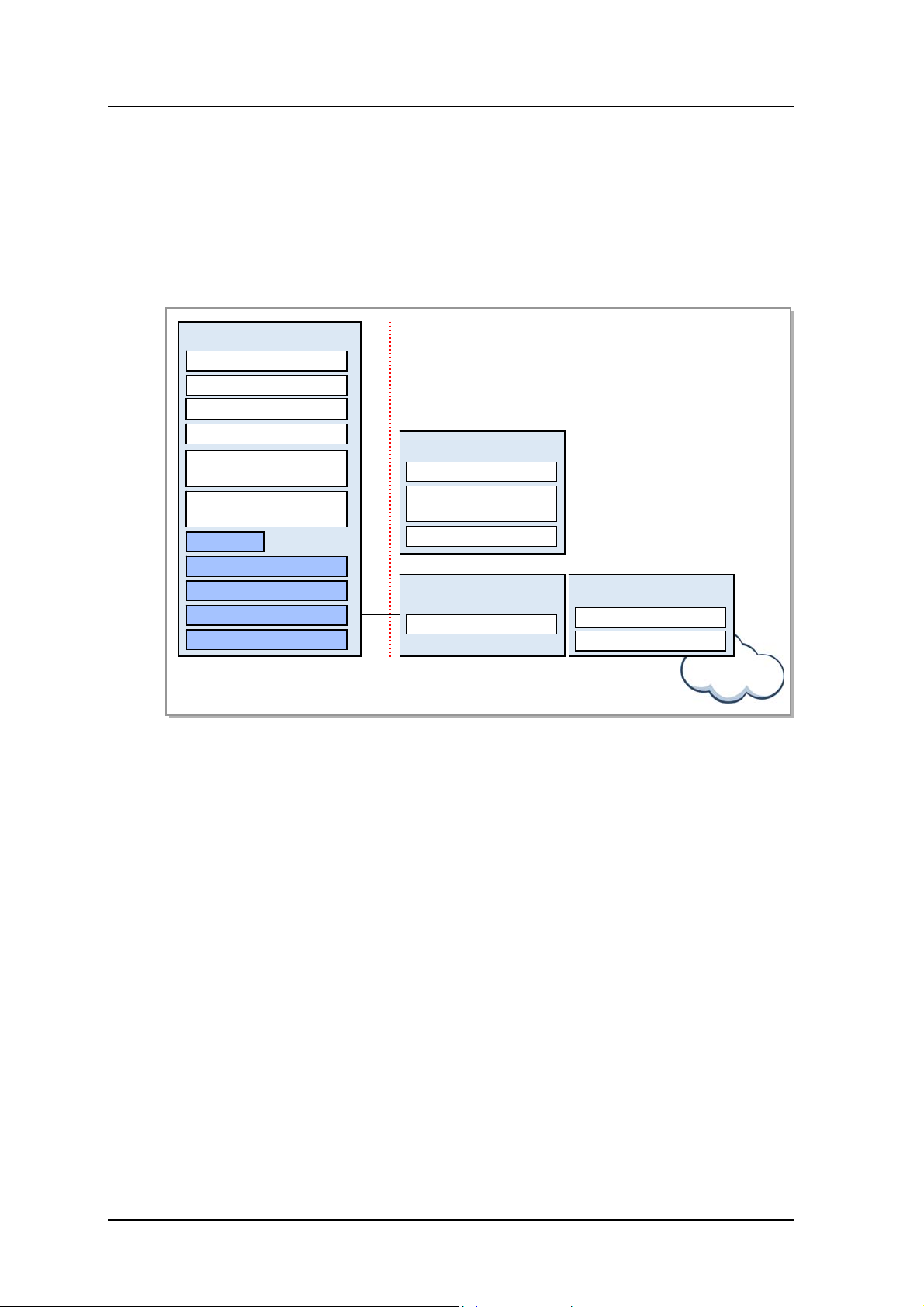
1.3 LTE System Functional Architecture
The eNB manages UEs, which are in connected mode, at the AS (Access Stratum) level.
The MME manages UEs, which are in idle mode, at the NAS (Non-Access Stratum) level,
and the P-GW manages user data at the NAS level as well as working with other networks.
The functional architecture of E-UTRAN eNB, MME, S-GW, and P-GW according to the
3GPP standards is shown below. The eNB is structured in layers while the EPC is not.
eNB
Inter Cell RRM
RB Control
Connection Mobility Control
Radio Admission Control
S1
MME
NAS Security
Idle State Mobility
Handling
EPS Bearer Control
S-GW
Mobility Anchoring
P-GW
UE IP address allocation
Packet Filtering
eNB Measurement
Configuration & Provision
Dynamic Resource
Allocation (Scheduler)
RRC
PDCP
RLC
MAC
PHY
E-UTRA
N
EPC
Figure 1.2 Functions of E-UTRAN and EPC
Internet
eNB
The eNB serves the E-UTR
AN (Evolved UTRAN), a wireless access network in the LTE
system.
The eNBs are connected through the X2 interface whereas the eNB and EPC are connected
through S1 interface.
The eNB’s wireless protocol layers are divided into Layer 2 and Layer 3. Layer 2 is
subdivided into the MAC (Media Access Control) layer, RLC (Radio Link Control) layer,
and PDCP layer, each operating independently. Layer3 has the RRC layer.
The MAC layer distributes wireless resources to each bearer according to its priority, and
carries out the multiplexing function and the HARQ function for the data received from the
multiple upper logical channels.
The RLC layer carries out the following functions.
Reconstructs the data received from the PDCP layer in accordance with the size
specified by the MAC layer (segmentation and reassembly).
1-4
When data transmission fails in the lower layer, requests retransmission to recover
them (ARQ).
Reorders the data recovered by performing HARQ in the MAC layer.
© SAMSUNG Electronics Co., Ltd.

LTE eNB System Description/Ver.1.0
The PDCP layer carries out the following functions.
Compresses and decompresses headers
Encrypts and decrypts the user plane and control plane data
Protects and verifies data integrity of the control plane
Transmits data and manages serial numbers
Removes data based on a timer as well as removing duplicates
The RRC layer is responsible for managing mobility in the wireless access network,
keeping and controlling the RB (Radio Bearer), managing RRC connections, and sending
system information.
Mobility Management Entity (MME)
The MME works with the
E-UTRAN (eNB), handlin
g S1-AP (S1 Application Protocol)
signaling messages in the SCTP (Stream Control Transmission Protocol) base to control
call connections between the MME and eNB as well as handling NAS signaling messages
in the SCTP base to control mobility and call connections between the UE and EPC.
The MME also works with the HSS to obtain, modify and authenticate subscriber
information, and works with the S-GW to request assignment, release and modification of
bearer paths for data routing and forwarding using the GTP-C protocol.
The MME can work with the 2G and 3G systems, SGSN, and MSC to provide mobility,
HO (Handover), CS (Circuit Service) fallback, and SMS (Short Message Service) services.
The MME is also responsible for managing mobility between eNBs, idle-mode UE
reachability, TA (Tracking Area) list as well as for P-GW/S-GW selection, authentication,
and bearer management.
MME supports the handover between MMEs and provides the mobility for the handover
between the eNBs.
It also supports the SGSN selection function upon handover to a 2G or 3G 3GPP network.
Serving Gateway (S-GW)
The S-GW
carries out the m
obility anchor function upon inter-eNB handover and inter3GPP handover, and processes routing and forwarding of packet data. The S-GW allows
the operator to set a different charging policy by UE, PDN or QCI, and manages the packet
transport layer for uplink/downlink data. The S-GW also works with the MME, P-GW, and
SGSN to support the GTP (GPRS Tunneling Protocol) and PMIP (Proxy Mobile IP).
PDN Gateway (P-GW)
The P-GW
works with PCRF to carry
out charging and bearer policies, and manage the
charging and transmission rate based on the service level. It also provides packet filtering
per subscriber, assigns IP addresses to UEs, and manages the packet transmission layer of
the downlink data.
© SAMSUNG Electronics Co., Ltd. 1-5

CHAPTER 1. Overview of Samsung LTE System
This page is intentionally left blank.
1-6
© SAMSUNG Electronics Co., Ltd.

LTE eNB System Description
CHAPTER 2. Overview of LTE eNB
2.1 Introduction to LTE eNB
The LTE eNB system is located between the UE and EPC, and interfaces via a wireless
connection according to the LTE Air Interface, providing subscribers with wireless
communication services. The eNB engages in sending and receiving radio signals with the
UE, and handling traffic modulation/demodulation signals. The LTE eNB is also
responsible for packet scheduling and wireless bandwidth allocation as well as for
handovers by interfacing with the EPC.
It consists of a DU (Digital Unit), i.e., UADU (Universal platform type A Digital Unit) and
a RU (Radio Unit), i.e., L8HU (LTE eNB remote radio Head Unit).
The UADU is a 19 inch shelf-type digital unit and can be mounted on a 19 inch rack in an
indoor/ outdoor environment.
The L8HU is an RF integration module consisting of a transceiver, power amplifier, and
filter. It sends and receives traffic, clock information, and alarm/control messages to and
from the L9CA. The L8HU has a 2Tx/4Rx structure with optic CPRI support, and can be
installed on a wall or pole in an outdoor environment.
© SAMSUNG Electronics Co., Ltd. 2-1
CHAPTER 2. Overview of LTE eNB
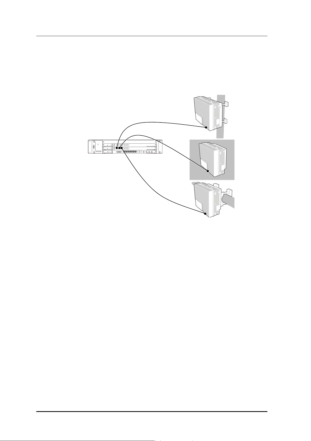
The LTE eNB can be installed as shown below:
Indoor eNB + L8HU
The L9CA from
the UADU mounted on an indoor 19 inch rack is connected to the L8HU.
The L8HU can be installed on a wall or pole.
Figure 2.1 Indoor eNB + L8HU Instal lation
2-2
© SAMSUNG Electronics Co., Ltd.
LTE eNB System Description/Ver.1.0
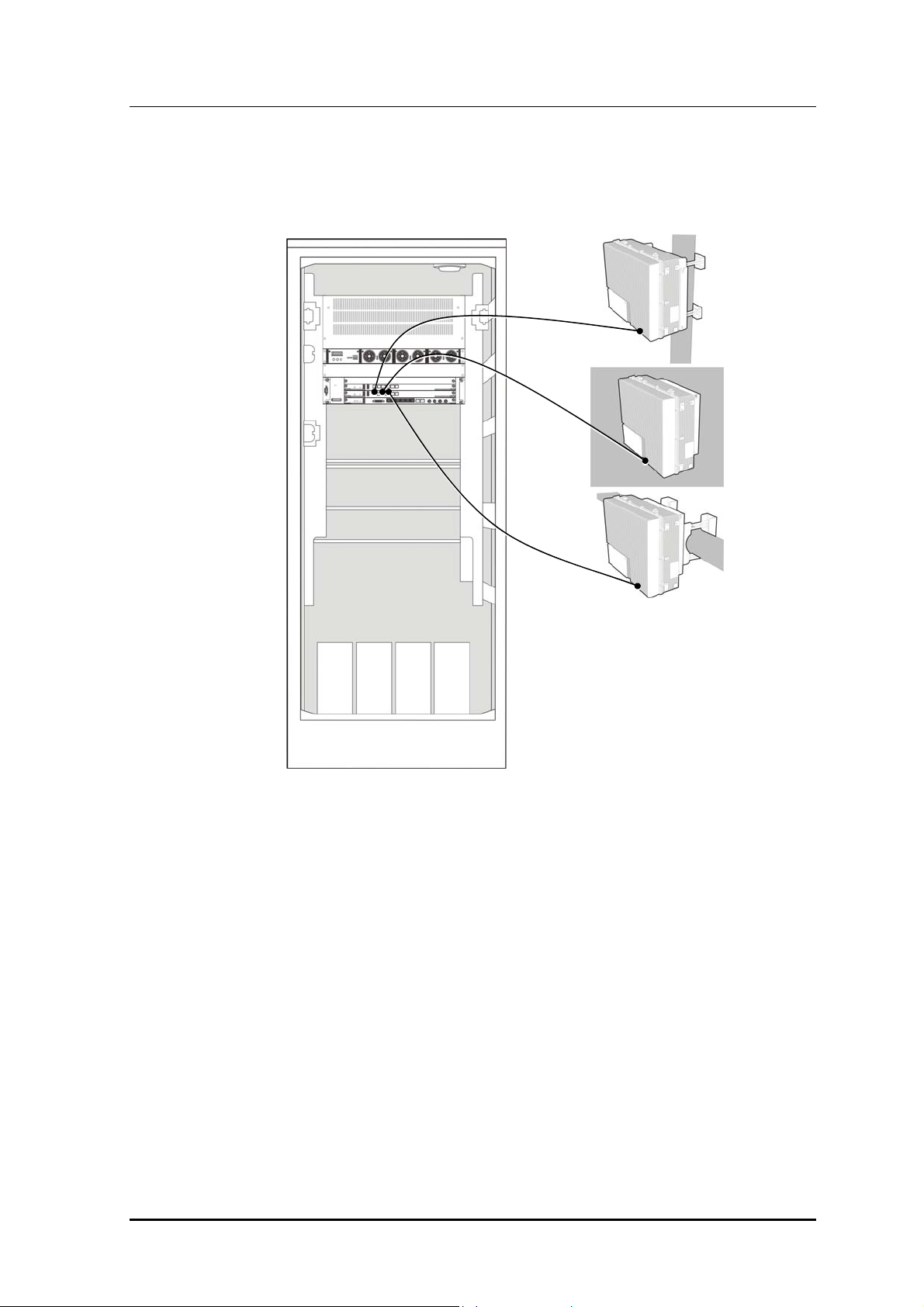
Outdoor eNB + L8HU
The L9CA from the UADU mounted on an outdoor rack is connected to the L8HU.
The L8HU can be installed on a wall or pole.
Figure 2.2 Outdoor eNB + L8HU Installation
© SAMSUNG Electronics Co., Ltd. 2-3

CHAPTER 2. Overview of LTE eNB
The LTE eNB system has the following key features:
High Compatibility and Interoperability
Sams
ung LTE system adheres to specifications released in accordance with the 3GPP
standards, providing excellent compatibility and interoperability.
High-Performance Modular Structure
The L
TE eNB sy
stem uses a high-performance processor and has a modular structure that
allows an easy hardware and software upgrade.
Support for Advanced RF and Antenna Solutions
The L
TE eNB sy
stem adopted a power amplifier to support bandwidth for broadband
operation, and also supports MIMO (Multiple Input Multiple Output).
Maintenance with Enhanced Security
The L
TE eNB sy
stem provides security functions (SNMPv2c, SSH, FTP/SFTP, and
HTTPs) for all channels for operation and maintenance. It authenticates operators accessing
the system, grants them permissions, and stores their system execution histories as logs.
6Rx Multi Antenna Support
Co
m
pared to generic eNBs with 2Rx antennas that receive 2Rx in one sector, Samsung
LTE eNB has enhanced reception, receiving antenna signals up to 6Rx from its own sector
as well as from the repeater mode.
OFDMA/SC-FDMA Scheme
The L
TE eNB perform
s the downlink OFDMA/uplink SC-FDMA (Single Carrier
Frequency Division Multiple Access) channel processing that supports the standard LTE
physical layer.
The downlink OFDMA allows the system to transmit data to multiple users simultaneously
using the subcarrier allocated to each user. Depending on the channel status and the
transmission rate requested by the user, the downlink OFDM can allocate one or more
subcarriers to a specific subscriber to transmit data. Moreover, when all subcarriers are
divided for multiple users, the FDMA can select and assign to each subscriber a subcarrier
with the most appropriate features, distributing resources efficiently and increasing data
throughput.
The uplink SC-FDMA, which is similar to the modulation/demodulation method of the
OFDMA, minimizes the PAPR (Peak-to-Average Power Ratio) of the transmitter by
computing, for each user, DFT (Discrete Fourier Transform) during modulation at the
transmitting end, and IDFT (Inverse Discrete Fourier Transform) during demodulation at
the receiving end, and continuously assigns frequency resources to users. As a result, it
saves the UE’s power.
2-4
© SAMSUNG Electronics Co., Ltd.

LTE eNB System Description/Ver.1.0
Support for Multiple System Configurations
The LTE eNB supports multiple system and network configurations with a digital unit
(UADU) and radio unit (RRH: Remote Radio Head). The digital I/Q and C & M (Control &
Maintenance) interface based on the CPRI (Common Public Radio Interface) standard is
used between the DU and RU to send and receive data traffic signals and OAM
information, and uses optic cable physically.
The UADU and L8HU each have a power supply of DC -48 V.
Multiple Configurations for Network Operation
The LTE eNB supports multiple configurations including RRH (L8HU).
The RRH is highly flexible in its installation, and helps with setting up a network in a
variety of configurations depending on the location and operation method.
Easy Installation
The optic interface component that interfaces with the UADU and the RF signal
processing component is integrated into the RRH, which becomes a very small and
very light single unit. The L8HU can be installed on a wall or pole.
Moreover, as the distance between the RRH and antenna is minimized, the loss of RF
signals due to the antenna feeder line can be reduced so that the line can provide more
enhanced RF receiving performance than the existing rack-type eNB.
Natural Cooling
Because the RRH is installed outdoors and has an efficient design, it can radiate heat
efficiently without any additional cooling system. No additional maintenance cost is
needed for cooling the RRH.
Loopback T e st
The LTE eNB provides the loopback test function to check whether communication is
normal on the Digital I/Q and C & M interface line between the DU and RU.
Remote Firmware Downloading
Operators can upgrade the L8HU and its service by replacing its firmware.
They can download firmware to the L8HU remotely using a simple command from the
LSM without visiting field stations.
As a result, the number of visits is minimized, leading to reduced maintenance costs
and system operation with ease.
Monitoring Port
Operators can monitor the information for an L8HU using its debug port.
MIMO Support
The LTE eNB supports 2Tx/2Rx or
4Tx/4Rx MIMO by default using multiple antennas.
MIMO has the following techniques.
SFBC (Space Frequency Block Coding)-Downlink
Reliability for the links is increased. (Note that the peak data rate is not increased.)
This technology implements Space Time Block Coding (STBC) not on time but on
frequency.
For 2 Tx: The method similar to STBC (Alamouti codes) is used.
For 4 Tx: Both the SFBC and Frequency Switched Transmit Diversity (FSTD) are
used simultaneously.
© SAMSUNG Electronics Co., Ltd. 2-5

CHAPTER 2. Overview of LTE eNB
SM (Spatial Multiplexing)-Downlink
This technology can increase the peak data rate by dividing and sending other data
via multiple antenna paths. (Each path uses the same time/frequency resource.)
SU (Single User)-MIMO: SM between the eNB and single UE, it increases the
UE’s peak data rate.
MU (Multi-User)-MIMO: SM between the eNB and multiple UEs; it increases cell
throughput instead of the UE peak data rate.
Open-loop SM: Runs without the UE’s PMI (Precoding Matrix Indicator) feedback
when the channel changes quickly or is unknown due to the UE’s fast mobility.
Closed-loop SM: Runs with the UE’s PMI feedback received from the eNB when
there is channel information due to the UE’s slow mobility.
UL (Uplink) Transmit Antenna Selection-Uplink
The UE uses one RF chain and 2Tx antennas. The eNB informs the UE which Tx
antenna to use.
Closed-loop selection of Tx antenna
MU (Multi-User) MIMO or Collaborative MIMO-Uplink
SM in which two UEs use the same time/frequency resources in the UL
simultaneously to transmit different data.
Each UE uses a single Tx antenna.
The eNB selects two orthogonal UEs.
There is an increase in overall cell throughput, but not in each UE’s peak data rate.
2-6
© SAMSUNG Electronics Co., Ltd.

LTE eNB System Description/Ver.1.0
2.2 Key Functions
Samsung LTE eNB has the following key features.
Physical layer processing
Call processing
IP processing
SON
Convenient operation and maintenance
2.2.1 Physical layer processing
The LTE eNB sends/receives data via wireless channels between the eNB and UE.
The eNB handles the following:
Downlink reference signal generation/transmission
Downlink synchronization signal generation/transmission
Channel encoding/decoding
Modulation/demodulation
Resource allocation and scheduling
Link adaptation
HARQ
Power control
ICIC
MIMO
Downlink reference signal generation/transmission
The reference signal is used to demodulate downlink
signals in the UE, and to measure the
characteristics of the channel for scheduling, link adaptation, and handover.
Cell-specific and UE-specific reference signals are used when transmitting non-MBSFN.
The cell-specific reference signal is used to measure the quality of the channel, calculate
the MIMO rank, perform MIMO precoding matrix selection, and measure the strength of
the signals for handover. To operate MIMO, a different reference signal is sent for each
antenna path.
Downlink Synchronization Signal Generation/Transmission
The sy
onization signal is used to perform the initial synchronization when the UE
nchr
starts to communicate with the base station. It can be PSS (Primary Synchronization
Signal) or SSS (Secondary Synchronization Signal). The UE obtains cell identify through
the synchronization signal, and other cell information through the broadcast channel.
Transmission in the synchronization signal and broadcast channel occurs at 1.08 MHz of
the cell’s channel bandwidth as the UE can identify cell ID and other basic information
regardless of the eNB’s transmission bandwidth.
© SAMSUNG Electronics Co., Ltd. 2-7

CHAPTER 2. Overview of LTE eNB
Channel encoding/decoding
The LTE eNB encodes/decodes the channel to correct channel errors over the wireless
channel. To do this, the LTE eNB uses turbo coding and 1/3 tail-biting convolutional
coding. Turbo coding is used primarily to transmit large downlink/uplink data packets, and
1/3 tail-biting convolutional coding to transmit downlink/uplink control information and
for the broadcast channel.
Modulation/Demodulation
When receiving downlink
data fro
m the upper layer, the LTE eNB processes it through the
baseband procedure of the physical layer and then transmits it via a wireless channel.
At this time, to send the baseband signals as far as they can go via the wireless channel, the
LTE eNB modulates them and sends them on a specific high frequency bandwidth.
For the uplink, the eNB demodulates the data transmitted over the wireless channel from
the UE to a baseband signal, which is then decoded.
Resource Allocation and Scheduling
For mu
ltiple access, the LTE uses the OFDMA for downlink and the SC-FDMA for uplink.
Both schemes allocate 2-dimensional time/frequency resources to multiple UEs in a cell,
allowing a single eNB to communicate with the multiple UEs simultaneously.
When in MU-MIMO mode, several UEs can use the same resources at the same time as an
exceptional case. Allocating cell resources to multiple UEs is called ‘scheduling’ and each
cell has an independent scheduler.
The scheduler is designed to consider the channel environment, the requested data
transmission rate and other various QoS factors of each UE, and perform an optimal
resource allocation to provide maximum total cell throughput. It also can share information
with other cell schedulers via the X2 interface to reduce interferences with the other cells.
2-8
Link Adaptation
The transm
ission rate and channel environment in the
wireless channel change according to
circumstances. Link adaptation is a feature to increase transmission speed or maximize
overall cell throughput using channel circumstances when they are known.
MCS (Modulation Coding Scheme) is a link adaptation method that sets the modulation
type and channel coding rate depending on the channel circumstances. If the channel
circumstances are good, the MCS increases the number of transmission bits per symbol
using high-order modulation, such as 64 QAM. If the circumstances are bad, it uses loworder modulation, such as QPSK, and a low coding rate to minimize channel errors.
The MCS can run in MIMO mode if the channel environment allows MIMO, increasing
the user’s peak data rate or cell throughput.
If channel information turns out to be different from the actual case, or if the order given to
the modulation or coding rate for the channel circumstances is higher than necessary, an
error can occur, but be recovered by HARQ.
© SAMSUNG Electronics Co., Ltd.

LTE eNB System Description/Ver.1.0
HARQ
HARQ is a technique for physical layer retransmission using the stop-and-wait protocol.
The LTE eNB runs the HARQ, retransmitting or combining frames in the physical layer in
order to increase throughput so that the impact from changes of the wireless channel
environment or interference signal level can be minimal. The LTE uses the IR (Incremental
Redundancy)-based HARQ. The CC (Chase Combining) method is treated as a special case
of the IR scheme. It uses the asynchronous IR for downlink, and the synchronous IR for
uplink.
Power Control
Power control refers to adjusting the tra
smission power level required to transmit a
n
specific data rate. Too much power causes interferences. Too little power increases the
error rate, causing a retransmission or delay.
Power control is less important in the LTE than in the CDMA, but a proper power control
can enhance the LTE’s system performance. The LTE uses the SC-FDMA scheme for
uplink and eliminates the near-far problem from the CDMA, but the UEs should transmit
with optimal power to avoid interference with neighbor cells as the high level of
interference with the neighbor cells can worsen the uplink performance. The LTE uplink
can lower the inter-cell interference level by adjusting the UE power. The downlink can
lower the inter-cell interference level by transmitting with optimal power according to the
UE location and MCS, increasing overall cell throughput.
Inter-Cell Interference Coordination (ICIC)
Unlike the CDMA, the L
TE does not
have intra-cell interference. This is because UEs in a
cell use orthogonal resources and thus there is no interference between them. However, in
the event that the adjacent cells are considered, unavoidable interference occurs when other
UEs use the same resource. Since this symptom is severe between the UEs located on a cell
edge, performance on the cell edge may be degraded. Inter-cell interference is not severe
for the UEs located close to the eNB because they receive much less interference from the
adjacent eNBs than the UEs located on the cell edge. A technique used to address the intercell interference problem on the cell edge is ICIC.
ICIC allows interference signals to be transmitted to other cells in the cell edge area in as
small an amount as possible by allocating a basically different resource to each UE that
belongs to a different cell and by carrying out power control according to the UE’s location
in the cell. To prevent interference due to resource conflict on the cell edge, ICIC transmits
scheduling information between base stations via the X2 interface. When the neighbor
cell’s interference signal strength is too strong, ICIC notifies other base stations to control
the interference, improving overall cell performance.
MIMO
The L
TE eNB supports 2Tx/2Rx or
4Tx/4Rx MIMO by default using multiple antennas.
To achieve this, there must be in the eNB channel card the RF part that can separately
process the baseband part and each path for MIMO processing. The LTE eNB provides
high-performance data services by supporting several types of MIMO.
© SAMSUNG Electronics Co., Ltd. 2-9
CHAPTER 2. Overview of LTE eNB
2.2.2 Call Processing
Cell Information Transmission
The LTE eNB periodically transmits, within the cell range being served, system information,
i.e., the MIB (Master Information Block) and SIBs (System Information Blocks), which are
then received by UEs to process calls appropriately.
Call Control and Air Resource Assignment
The L
TE eN
B allows the UE to be connected to or released from the network.
When the UE is connected to or released from the network, the LTE eNB sends and
receives the signaling messages required for call processing to and from the UE via the Uu
interface, and to and from the EPC via the S1 interface.
When the UE connects to the network, the eNB carries out call control and resource
allocation required for service. When the UE is released from the network, the eNB collects
and releases the allocated resources.
Handover Processing
The L
TE eNB supports intra-frequency or inter
-frequency handover between intra-eNB
cells, X2 handover between eNBs, and S1 handover between eNBs, and carries out the
signaling and bearer processing functions required for handover. At intra-eNB handover,
handover-related messages are transmitted via internal eNB interfaces; at X2 handover, via
the X2 interface; at S1 handover, via the S1 interface.
The eNB carries out the data forwarding function to minimize user traffic disconnections at
X2 and S1 handovers. The source eNB provides two forwarding methods to the target eNB,
direct forwarding via the X2 interface and indirect forwarding via the S1 interface.
The eNB allows the UE to receive traffic without loss through the data forwarding method
at handover.
Handover Procedure
For more on the handover procedure, refer to Chapter 4. Message Flow.
Admission Control (AC)
The LTE eN
B provides capacity-based and QoS-based admission control for bearer setup
requests from the EPC to avoid system overload. Capacity-based admission control and
QoS-based admission control operate as follows respectively.
2-10
Capacity-based admission control
There is a threshold for the maximum number of connected UEs (new calls/handover
calls) and a threshold for the maximum number of connected bearers that can be
allowed in the eNB. When a call setup is requested, the permission is determined
depending on whether the connected UEs and bearers exceed the thresholds.
© SAMSUNG Electronics Co., Ltd.

LTE eNB System Description/Ver.1.0
QoS-based admission control
The eNB provides the function for determining whether to permit a call depending on
the estimated PRB usage of the newly requested bearer, the PRB usage status of the
bearers in service, and the maximum acceptance limit of the PRB (per bearer type,
QCI, and UL/DL).
RLC ARQ
The eNB carries out the
ARQ function f
or the RLC Acknowledged Mode (AM) only.
The RLC can increase reliability of data communications by dividing the Service Data Unit
(SDU) into the Protocol Data Unit (PDU) prior to transmission, and retransmitting the
packets according to ARQ feedback from the receiver.
QoS Support
The eNB re
ce
ives the QoS Class Identifier (QCI) in which the QoS characteristics of the
bearer are defined, and the Guaranteed Bit Rate (GBR), the Maximum Bit Rate (MBR),
and the Aggregated Maximum Bit Rate (AMBR) from the EPC. It provides the QoS for the
wireless section between the UE and the eNB and the backhaul section between the eNB
and the S-GW.
In the wireless section, it carries out retransmission to satisfy the rate control due to the
GBR/MBR/AMBR value, priority of bearer defined in the QCI, and scheduling considering
packet delay budget, and Packet Loss Error Rate (PLER).
In the backhaul section, the eNB carries out QCI-based packet classification, QCI to DSCP
mapping, and marking for the QoS. The eNB provides queuing based on mapping results,
and each queue transmits packets to the EPC according to strict priority, etc.
In the EMS (Element Management System), besides the QCI predefined in the
specifications, an operator specific QCI and a QCI-to-DSCP mapping can be set.
© SAMSUNG Electronics Co., Ltd. 2-11

CHAPTER 2. Overview of LTE eNB
2.2.3 IP Processing
IP QoS
The LTE eNB can provide the backhaul QoS when communicating with the EPC by
supporting the Differentiated Services (DiffServ).
The LTE eNB supports eight backhaul QoS classes as well as mapping between the user
traffic service class and the backhaul QoS class. It also supports mapping between the
Differentiated Services Code Points (DSCP) and the 802.3 Ethernet MAC service classes.
IP Routing
The L
TE eN
B provides several Ethernet interfaces and stores in the routing table
information on which Ethernet interface IP packets will be routed.
The LTE eNB’s routing table is configured by the operator. The table configuration and its
setting are similar to standard router settings.
The LTE eNB supports static routing settings, but doesn’t support dynamic routing
protocols such as OSPF (Open Shortest Path First) or BGP (Border Gateway Protocol).
Ethernet/VLAN Interfacing
The LTE eNB provides Et
hernet interfaces, and supports static link grouping, VLAN
Virtual Local Area Network(VLAN), and Ethernet Class of Service(CoS) functions that
comply with IEEE 802.3ad for Ethernet interfaces. A MAC bridge defined in IEEE 802.1D
is excluded.
The LTE eNB allows multiple VLAN IDs for an Ethernet interface. To support the Ethernet
CoS, it maps the DSCP value of the IP header to the CoS value of the Ethernet header for
Tx packets.
2-12
© SAMSUNG Electronics Co., Ltd.

LTE eNB System Description/Ver.1.0
2.2.4 SON
System Self-Configuration and Self-Establishment
The self-configuration and the self-establishment automatically configure and establish
radio parameters between the power-on stage and the service stage to minimize efforts in
installing a base station. The detailed functions are as follows.
Self-configuration
Initial PCI (Physical Cell Identity) self-configuration
Initial neighbor information self-configuration
Initial PRACH (Physical Random Access Channel) self-configuration
Self-establishment
Automatic IP address acquisition
Automatic OAM connectivity
S/W and Configuration data loading
Automatic S1/X2 setup
Self-test
Self-Optimization
PCI auto-configuration
The SON server of the LSM provides the function for allocating the initial PCI in the
self-establishment procedure of a new eNB, and the function for detecting a problem
automatically and selecting, changing, and setting a proper PCI when a PCI
collision/confusion occurs with the adjacent cells during operation.
Automatic Neighbor Relation (ANR) optimization
ANR optimization minimizes the network operator’s effort to maintain the optimal
NRT by dynamically managing the Neighbor Relation Table (NRT) according to the
addition/removal of neighbor cells. It needs to automatically configure each eNB’s
initial NRT, and recognize environment changes, such as cell addition/removal or new
eNB installations during operation to maintain the optimal NRT. In other words, the
ANR function updates the NRT for each eNB by automatically recognizing the
topology change such as new adjacent cell or eNB installation/removal and adding or
removing the Neighbor Relation (NR) to or from a new adjacent cell.
Mobility robustness optimization
The mobility robustness optimization function is the function for improving handover
performance in the eNB by recognizing the problem that handover is triggered at the
incorrect time (e.g., too early or too late) before, after, or during handover depending
on UE mobility, or handover is triggered to the incorrect target cell (handover to the
wrong cell) and then by optimizing the handover parameters according to the reasons
for the problem.
Energy Saving Management (ESM)
The energy saving feature helps reduce the LTE eNB’s power consumption. The ESM
adjusts power consumption automatically according to the specified schedule or
through traffic quantity analysis. The basic principle is that power consumption is
reduced by limiting the number of used Resource Blocks (RBs) and adjusting the PA
bias voltage.
© SAMSUNG Electronics Co., Ltd. 2-13

CHAPTER 2. Overview of LTE eNB
Random Access Channel (RACH) optimization
RACH optimization (RO) can minimize access delay and interference by dynamically
managing parameters related to random access. The RO function is divided into the
initial RACH setting operation and the operation for optimizing parameters related to
the RACH. The initial RACH setting operation is for setting the preamble signatures
and the initial time resource considering the neighbor cells. The operation for
optimizing parameters related to the RACH is for estimating the RACH resources,
such as time resource and subscriber transmission power required for random access,
that change depending on time, and for optimizing the related parameters.
2.2.5 Convenient Operation and Maintenance
The LTE eNB works with management systems (LSM, Web-EMT, CLI) to operate
maintenance activities, such as resetting/restarting a system as well as managing system
configurations, failure/status/diagnosis of system resources and services, statistics on
system resources and various performance data, and security for system access and operation.
Graphics and Text Based Console Interfaces
The LSM ma
s the entire eNB system using the Database Management System (DBMS).
nage
The eNB also works with a console terminal to allow the operator to connect directly to the
Network Element (NE), not through the LSM, for operation and maintenance activities.
The operator can choose between the graphic-based console interface (Web-EMT, Webbased Element Maintenance Terminal) or the text-based Command Line Interface(CLI) to
suit operational convenience and purpose.
The operator can access the console interfaces without separate software. For the Web-EMT,
the operator can log in to the system using Internet Explorer. For the CLI, the operator can
log in to the system using the telnet or Secure Shell (SSH) in the command window.
Tasks such as managing configurations and operational information, failures and statuses,
and monitoring statistics can be done through the terminal. However, increasing/decreasing
resources or configuring neighbor lists in which multiple NEs are related can only be
performed using the LSM.
Operator Authentication
The eNB c
a
n authenticate system operators and manage their privileges.
An operator accesses the eNB using the operator’s account and password through the CLI.
The eNB grants an operational privilege in accordance with the operator’s level.
The eNB logs successes/failures of access to the CLI, activities during the login, etc.
2-14
Maintenance with Enhanced Security
The eNB supports the SNMP
(Sim
ple Network Management Protocol) and SFTP (SSH File
Transfer Protocol) for security during communications with the LSM, and the HTTPs
(Hyper Text Transfer Protocol over SSL) and SSH (Secure Shell) during communications
with the console terminal.
© SAMSUNG Electronics Co., Ltd.

LTE eNB System Description/Ver.1.0
Online Software Upgrade
When a software package is upgraded, the EPC can upgrade the existing package while it is
still running. A package upgrade is performed in the following steps: download new
package (Add) and change to the new package (Change).
When upgrading the package, the service stops temporarily during the ‘change to the new
package’ step to exit the existing process and start the new process. But the operating
system does not restart, so it can provide the service within several minutes.
After upgrading the software, the eNB updates the package stored in the internal
nonvolatile storage.
Call Trace
When tracing calls for a specific UE usi
ng the MME, the eNB tran
smits to the LSM a
signaling message for the call in the UE.
OAM Traffic Throttling
The eNB provides the ope
rator with the function f
or suppressing the OAM-related traffic
that can occur in the system using an operator command. At this time, the target OAMrelated traffic includes the fault trap messages for alarm reporting and the statistics files
generated periodically.
For the fault trap messages, the operator can suppress generation of alarms for the whole
system or some fault traps using the alarm inhibition command, consequently allowing the
operator to control the amount of alarm traffic that is generated. For the statistics files, the
operator can control the amount of statistics files by disabling the statistics collection
function for each statistics group using the statistics collection configuration command.
© SAMSUNG Electronics Co., Ltd. 2-15
 Loading...