

Samsung PLK405WX-XAC, SLK407WX-XAC Service Manual
LCD PROJECTION TELEVISION
Chassis : L56A
Model : PLK405WX/XAC
SLK407WX/XAC
LCD PROJECTION TELEVISION CONTENTS
Precautions
Reference Information
Specifications
Disassembly and Reassembly
Alignment and Adjustments
Troubleshooting
Exploded View and Parts List
Electrical Parts List
Block Diagram
Wiring Diagram
Schematic Diagrams
1.
2.
3.
4.
5.
6.
7.
8.
9.
10.
11.

ELECTRONICS
© Samsung Electronics Co., Ltd. SEP. 2000
Printed in Korea
3L56A-4020

1. Precautions
1-1 Safety Precautions
1. Be sure that all of the built-in protective
devices are replaced. Restore any missing
protective shields.
2. When reinstalling the chassis and its
assemblies, be sure to restore all protective
devices, including: nonmetallic control knobs
and compartment covers.
3. Make sure that there are no cabinet openings
through which people—particularly
children—might insert fingers and contact
dangerous voltages. Such openings include
the spacing between the picture tube and the
cabinet mask, excessively wide cabinet
ventilation slots, and improperly fitted back
covers.
If the measured resistance is less than 1.0
megohm or greater than 5.2 megohms, an
abnormality exists that must be corrected
before the unit is returned to the customer.
4. Leakage Current Hot Check (Figure 1-1):
Warning: Do not use an isolation
transformer during this test. Use a leakagecurrent tester or a metering system that
complies with American National Standards
Institute (ANIS C101.1, Leakage Current for
Appliances), and Underwriters Laboratories
(UL Publication UL1410, 59.7).
5. With the unit completely reassembled, plug
the AC line cord directly into the power
outlet. With the unit’s AC switch first in the
ON position and then OFF, measure the
current between a known earth ground (metal
water pipe, conduit, etc.) and all exposed
metal parts, including: antennas, handle
brackets, metal cabinets, screwheads and
control shafts. The current measured should
not exceed 0.5 milliamp. Reverse the powerplug prongs in the AC outlet and repeat the
test.
Fig. 1-1 AC Leakage Test
6. Antenna Cold Check:
With the unit’s AC plug disconnected from the
AC source, connect an electrical jumper across
the two AC prongs. Connect one lead of the
ohmmeter to an AC prong. Connect the other
lead to the coaxial connector.
7. X-ray Limits:
The picture tube is especially designed to prohibit X-ray emissions. To ensure continued
X-ray protection, replace the picture tube only
with one that is the same type as the original.
Carefully reinstall the picture tube shields and
mounting hardware; these also provide X-ray
protection.
8. High Voltage Limits:
High voltage must be measured each time servicing is done on the B+, horizontal deflection
or high voltage circuits. Correct operation of
the X-ray protection circuits must be
reconfirmed whenever they are serviced.
(X-ray protection circuits also may be called
“horizontal disable” or “hold-down”.)
Heed the high voltage limits. These include
the X–ray Protection Specifications Label, and
the Product Safety and X-ray Warning Note on
the service data schematic.
Precautions
Samsung Electronics 1-1
LEAKAGE
CURRENT
TESTER
DEVICE
UNDER
TEST
TEST ALL
EXPOSED METAL
SURFACES
2-WIRE CORD
ALSO TEST WITH
PLUG REVERSED
(USING AC ADAPTER
PLUG AS REQUIRED)
EARTH
GROUND
(READING SHOULD
NOT BE ABOVE
0.5mA)
Follow these safety, servicing and ESD precautions to prevent damage and protect against potential
hazards such as electrical shock and X-rays.

1-1 Safety Precautions (Continued)
9. High voltage is maintained within specified
limits by close-tolerance, safety-related
components and adjustments. If the high
voltage exceeds the specified limits, check
each of the special components.
10. Design Alteration Warning:
Never alter or add to the mechanical or
electrical design of this unit. Example: Do not
add auxiliary audio or video connectors. Such
alterations might create a safety hazard. Also,
any design changes or additions will void the
manufacturer’s warranty.
11. Hot Chassis Warning:
Some TV receiver chassis are electrically
connected directly to one conductor of the AC
power cord. If an isolation transformer is not
used, these units may be safely serviced only
if the AC power plug is inserted so that the
chassis is connected to the ground side of the
AC source.
To confirm that the AC power plug is inserted
correctly, do the following: Using an AC
voltmeter, measure the voltage between the
chassis and a known earth ground. If the
reading is greater than 1.0V, remove the AC
power plug, reverse its polarity and reinsert.
Re-measure the voltage between the chassis
and ground.
12. Some TV chassis are designed to operate with
85 volts AC between chassis and ground,
regardless of the AC plug polarity. These units
can be safely serviced only if an isolation
transformer inserted between the receiver and
the power source.
13. Some TV chassis have a secondary ground
system in addition to the main chassis ground.
This secondary ground system is not
isolated from the AC power line. The two
ground systems are electrically separated by
insulating material that must not be defeated
or altered.
14. Components, parts and wiring that appear to
have overheated or that are otherwise
damaged should be replaced with parts that
meet the original specifications. Always
determine the cause of damage or overheating, and correct any potential hazards.
15. Observe the original lead dress, especially
near the following areas: Antenna wiring,
sharp edges, and especially the AC and high
voltage power supplies. Always inspect for
pinched, out-of-place, or frayed wiring. Do
not change the spacing between components
and the printed circuit board. Check the AC
power cord for damage. Make sure that leads
and components do not touch thermally hot
parts.
16. Picture Tube Implosion Warning:
The picture tube in this receiver employs
“integral implosion” protection. To ensure
continued implosion protection, make sure
that the replacement picture tube is the same
as the original.
17. Do not remove, install or handle the picture
tube without first putting on shatterproof
goggles equipped with side shields. Never
handle the picture tube by its neck. Some
“in-line” picture tubes are equipped with a
permanently attached deflection yoke; do not
try to remove such “permanently attached”
yokes from the picture tube.
18. Product Safety Notice:
Some electrical and mechanical parts have
special safety-related characteristics which
might not be obvious from visual inspection.
These safety features and the protection they
give might be lost if the replacement component differs from the original—even if the
replacement is rated for higher voltage,
wattage, etc.
Components that are critical for safety are
indicated in the circuit diagram by shading,
( ) or ( ).
Use replacement components that have the
same ratings, especially for flame resistance
and dielectric strength specifications.
A replacement part that does not have the
same safety characteristics as the original
might create shock, fire or other hazards.
Precautions
1-2 Samsung Electronics

1-2 Servicing Precautions
1. Servicing precautions are printed on the
cabinet. Follow them.
2. Always unplug the unit’s AC power cord from
the AC power source before attempting to: (a)
Remove or reinstall any component or
assembly, (b) Disconnect an electrical plug or
connector, (c) Connect a test component in
parallel with an electrolytic capacitor.
3. Some components are raised above the printed
circuit board for safety. An insulation tube or
tape is sometimes used. The internal wiring is
sometimes clamped to prevent contact with
thermally hot components. Reinstall all such
elements to their original position.
4. After servicing, always check that the screws,
components and wiring have been correctly
reinstalled. Make sure that the portion around
the serviced part has not been damaged.
5. Check the insulation between the blades of the
AC plug and accessible conductive parts
(examples: metal panels, input terminals and
earphone jacks).
6. Insulation Checking Procedure: Disconnect the
power cord from the AC source and turn the
power switch ON. Connect an insulation
resistance meter (500V) to the blades of the AC
plug.
The insulation resistance between each blade
of the AC plug and accessible conductive parts
(see above) should be greater than 1 megohm.
7. Never defeat any of the B+ voltage interlocks.
Do not apply AC power to the unit (or any of
its assemblies) unless all solid-state heat sinks
are correctly installed.
8. Always connect a test instrument’s ground
lead to the instrument chassis ground before
connecting the positive lead; always remove
the instrument’s ground lead last.
9. When some parts inside the optical engine
(except lamp) are damaged, replace the whole
optical engine.
Precautions
Samsung Electronics 1-3
Warning 1 : First read the “Safety Precautions” section of this manual. If some unforeseen circumstance creates a
conflict between the servicing and safety precautions, always follow the safety precautions.
Warning 2 : An electrolytic capacitor installed with the wrong polarity might explode.

1. Some semiconductor (“solid state”) devices
are easily damaged by static electricity. Such
components are called Electrostatically
Sensitive Devices (ESDs); examples include
integrated circuits and some field-effect
transistors. The following techniques will
reduce the occurrence of component damage
caused by static electricity.
2. Immediately before handling any semicon
ductor components or assemblies, drain the
electrostatic charge from your body by
touching a known earth ground. Alternatively,
wear a discharging wrist-strap device. (Be
sure to remove it prior to applying power—
this is an electric shock precaution.)
3. After removing an ESD-equipped assembly,
place it on a conductive surface such as
aluminum foil to prevent accumulation of
electrostatic charge.
4. Do not use freon-propelled chemicals. These
can generate electrical charges that damage
ESDs.
5. Use only a grounded-tip soldering iron when
soldering or unsoldering ESDs.
6. Use only an anti-static solder removal device.
Many solder removal devices are not rated as
“anti-static”; these can accumulate sufficient
electrical charge to damage ESDs.
7. Do not remove a replacement ESD from its
protective package until you are ready to
install it. Most replacement ESDs are
packaged with leads that are electrically
shorted together by conductive foam,
aluminum foil or other conductive materials.
8. Immediately before removing the protective
material from the leads of a replacement ESD,
touch the protective material to the chassis or
circuit assembly into which the device will be
installed.
9. Minimize body motions when handling
unpackaged replacement ESDs. Motions such
as brushing clothes together, or lifting a foot
from a carpeted floor can generate enough
static electricity to damage an ESD.
Precautions
1-4 Samsung Electronics
1-3 Precautions for Electrostatically Sensitive Devices (ESDs)

Reference Information
Samsung Electronics 2-1
2. Reference Information
2-1 Tables of Abbreviations and Acronyms
A
Ah
Å
dB
dBm
°C
°F
°K
F
G
GHz
g
H
Hz
h
ips
kWh
kg
kHz
kΩ
km
km/h
kV
kVA
kW
I
MHz
Ampere
Ampere-hour
Angstrom
Decibel
Decibel Referenced to One
Milliwatt
Degree Celsius
Degree Fahrenheit
degree Kelvin
Farad
Gauss
Gigahertz
Gram
Henry
Hertz
Hour
Inches Per Second
Kilowatt-hour
Kilogram
Kilohertz
Kilohm
Kilometer
Kilometer Per Hour
Kilovolt
Kilovolt-ampere
Kilowatt
Liter
Megahertz
MV
MW
MΩ
m
µA
µF
µH
µm
µs
µW
mA
mg
mH
mI
mm
ms
mV
nF
Ω
pF
Ib
rpm
rps
s
V
VA
W
Wh
Megavolt
Megawatt
Megohm
Meter
Microampere
Microfarad
Microhenry
Micrometer
Microsecond
Microwatt
Milliampere
Milligram
Millihenry
Milliliter
Millimeter
Millisecond
Millivolt
Nanofarad
Ohm
Picofarad
Pound
Revolutions Per Minute
Revolutions Per Second
Second (Time)
Volt
Volt-ampere
Watt
Watt-hour
Table 2-1 Abbreviations

Reference Information
2-2 Samsung Electronics
Table 2-2 Abbreviations
ABL
AC
ACC
AF
AFC
AFT
AGC
AM
ANSI
APC
APC
A/V
AVC
BAL
BPF
B-Y
CATV
CB
CCD
CCTV
Ch
CRT
CW
DC
DVM
EIA
ESD
ESD
FBP
FBT
FF
FM
FS
GND
G-Y
H
HF
HI-FI
IC
IC
IF
Automatic Brightness Limiter
Alternating Current
Automatic Chroma Control
Audio Frequency
Automatic Frequency Control
Automatic Fine Tuning
Automatic Gain Control
Amplitude Modulation
American National Standards Institute
Automatic Phase Control
Automatic Picture Control
Audio-Video
Automatic Volume Control
Balance
Bandpass Filter
Blue-Y
Community Antenna Television (Cable TV)
Citizens Band
Charge Coupled Device
Closed Circuit Television
Channel
Cathode Ray Tube
Continuous Wave
Direct Current
Digital Volt Meter
Electronics Industries Association
Electrostatic Discharge
Electrostatically Sensitive Device
Feedback Pulse
Flyback Transformer
Flip-Flop
Frequency Modulation
Fail Safe
Ground
Green-Y
High
High-Frequency
High Fidelity
Inductance-Capacitance
Integrated Circuit
Intermediate Frequency
I/O
L
L
LED
LF
MOSFET
MTS
NAB
NEC
NTSC
OSD
PCB
PLL
PWM
QIF
R
RC
RF
R-Y
SAP
SAW
SIF
SMPS
S/N
SW
TP
TTL
TV
UHF
UL
UV
VCD
VCO
VCXO
VHF
VIF
VR
VTR
VTVM
TR
Input/output
Left
Low
Light Emitting Diode
Low Frequency
Metal-Oxide-Semiconductor-Field-Effect-Tr
Multi-channel Television Sound
National Association of Broadcasters
National Electric Code
National Television Systems Committee
On Screen Display
Printed Circuit Board
Phase-Locked Loop
Pulse Width Modulation
Quadrature Intermediate Frequency
Right
Resistor & Capacitor
Radio Frequency
Red-Y
Second Audio Program
Surface Acoustic Wave(Filter)
Sound Intermediate Frequency
Switching Mode Power Supply
Signal/Noise
Switch
Test Point
Transistor Transistor Logic
Television
Ultra High Frequency
Underwriters Laboratories
Ultraviolet
Variable-Capacitance Diode
Voltage Controlled Oscillator
Voltage Controlled Crystal Oscillator
Very High Frequency
Video Intermediate Frequency
Variable Resistor
Video Tape Recorder
Vacuum Tube Voltmeter
Transistor

H001 AA40-10005R TUNER, TECC1070PG30A(S) SEMCO
H002 AA40-10005U TUNER, TCPN9082PC27A(S) SEMCO
IC601 AA96-50367A ASSY-H/S SOUND AMP TDA7265 PHILIPS
MAIN IC902 1103-000128 24C02, EEPROM ATMEC
IC905 0904-001121 PCF8574P, I/O EXPANDER PHILIPS
REL601 3501-000332 Relay-Power OMRON
X901 2801-0003120 CRYSTAL, 8.388Mhz KONY
IF IC101 1204-001435 IC-IF SYSTEM, LA7565B, DIP SANYO
MTS
H009 AA59-40003Q MODULE-MTS (MZ-202)
IC101 1204-001204 IC-DECODER,TDA9850,DIP,32P PHILIPS
3D-COMB IC01 1204-001556 C-SEPARATION, UPD64082GF NEC
IC02 1105-001172 IC-DRAM, 416C1204 SAMSUNG
IC04 1203-001419 IC-VOLTAGE REGULATOR, 4931 SGS
FD00,01,03 2909-001051 FILTER-LC, 6Mhz TOKO
FD02 2909-001052 FILTER-LC, 3.58Mhz TOKO
XTAL01 2801-000199 CRYSTAL-UNIT, 20Mhz
PIP & ICT00 1203-001419 IC-VOLTAGE REGULATOR, 4931
CAPTION ICT01 1204-001668 IC-PICTURE PROCESS, SDA9488X SIEMENS
ICT02 1001-001083 IC-VIDEO SWITCH, NJM2248D JRC
ICT03 1001-001083 IC-VIDEO SWITCH, NJM2248D JRC
ICT04 1204-001388 IC-DECODER, Z86129 Zilog
ICT05 1204-001610 IC-DECODER, Z86130 Zilog
XT00 2801-003432 CRYSTAL-UNIT, 20.25Mhz
Reference Information
Samsung Electronics 2-3
2-2 IC Line Up
Table 2 - 3 IC Line - Up
Assy
Component RemarksDescriptionLoc.No.

Reference Information
2-4 Samsung Electronics
ICP101 1204-001362 IC-VIDEO PROCESS, VPC3215C ITT
ICP103 1205-001172 IC-INTERFACE, CIP3250A ITT
ICP301 1204-001623 IC-VERTICAL PROCESSOR, SDA9400 SIEMENS
ICP302 1203-001419 IC-VOLTAGE REGULATOR, 4931
PROSCAN ICP401 1002-001045 IC-D/A CONVERTER, SDA9280 SIEMENS
ICP501 1204-001550 IC-VIDEO PROCESS, CXA2101AQ SONY
ICP601 1204-001372 IC-HOR./VER.PROCESSOR, SDA9361 SIEMENS
ICP901 1202-000001 IC-VOLTAGE COMP., 7533
XP101 2801-003432 CRYSTAL-UNIT, 20.25Mhz
XP601 2801-003811 CRYSTAL-UNIT, 24.576Mhz
ICL104,9 0801-000901 74HC04D PHILIPS
ICL106,7,8 1201-001083 CXA1211M SONY
LCD-CTRL ICL201,2,3 1002-000134 TDA8444 PHILIPS
ICL204 1003-001094 CXA1853Q SONY
ICL205 1003-001093 CXA2504N SONY
ICL301 1003-001095 CXD2443Q SONY
POWER
IC801 AA96-50366C ASSY-H/S, STR83145 SANKEN
IC802 AA98-50366B ASSY-H/S, STR-6709 SANKEN
Table 2 - 3 IC Line - Up (Continued)
Assy
Component RemarksDescriptionLoc.No.
Specifications
Samsung Electronics 3-1
3. Specifications
MODEL
TUNING
SYSTEM COLOUR
SOUND
ANTENNA IMPEDANCE
SCREEN SIZE
CONSUMPTION
POWER REQUIREMENTS
FREQUENCY
TUNING RANGE
SOUND OUTPUT
DIMENSIONS SET
PLH403W / PLK405W / SLK407W
Frequency Synthesizer
NTSC 3.58
Stereo System
75 ohm Unbalanced Coaxial
101.6 cm
170 Watts
Input : 120V
60 Hz
VHF CH : 2 ~13
UHF CH : 14 ~ 69
CATV CH : 1, 14 ~ 125
13 Watts/CH x 2
1012 x 349 x 736mm
(W x D x H) TRANSMITTER
WEIGHT SET
TRANSMITTER
Specifications are subject to change.
60 x 18 x 227mm
27 Kg
152g (Including Batteries)

3-2 Samsung Electronics
MEMO

Disassembly and Reassembly
Samsung Electronics 4-1
4. Disassembly and Reassembly
4-1 Back Cover Removal
1. After removing the 16 screws, pull the bottom part of the cabinet backwards.
2. Loosen the 4 screws and remove
the supporter.
4. Loosen the 2 screws. Remove the optical
meter.
3. After loosening the 4 screws, remove the lens
cover and fan duct.
5. Loosen the 2 screws. Remove the stabilizer.

Disassembly and Reassembly
4-2 Samsung Electronics
6. After loosening the 2 screws, remove the
chassis holder and power mounting.
7. After removing the 6 screws, pull the top
cabinet backwards.

Disassembly and Reassembly
Samsung Electronics 4-3
4-2 Lamp Replacement
1. Loosen the screw.
3. Using a hexagonal wrench, loosen the two
screws that secure the lamp.
2. Remove the cover.
4. Pull out the lamp.
5. PROCEDURE
After completing the lamp replacement, enter
the Service Mode
(use a remote control).
(1) Select the 84 (lamp life) with using the
volume DOWN key (See the figure below).
(2) Press the Mute key to reset the lamp life
(“0000”).
(3) Press the ADD key to exit.
LAMP
84 lamp life 0000

Disassembly and Reassembly
4-4 Samsung Electronics
4-2-1 Lamp (bulb only) Replacement
1. Loosen the two screws.
3. After loosening the two brackets, remove the
lamp-holder and wires.
2. Remove the lamp-bracket from the lamp
assembly.
4. After loosening one screw and one nut,
remove the bulb.

Disassembly and Reassembly
Samsung Electronics 4-5
4-3 Air Filter Check
2. Remove the cover.
3. After removing the holder and filter from the
cover, clean the filter.
1. Loosen the screw.
FILTER

Disassembly and Reassembly
4-6 Samsung Electronics
4-4 Liquid Crystal Panel Replacement
1. After removing the 16 screws, pull the cabinet
backwards.
3. After loosening the 4 screws, remove the lens
cover and fan duct.
5. Remove the GUIDE from the FPC-Connector.
2. Loosen the 3 screws. Remove the supporter.
4. Loosen the 2 screws. Remove the optical
meter.
6. Remove FPC cable from the FPC-Connector.

Disassembly and Reassembly
Samsung Electronics 4-7
7. Loosen the 4 screws and remove
the PCB-LCD.
9. Lift the LCD in the direction of arrow.
8. Using a hexagonal wrench, loosen the two
screws.

Disassembly and Reassembly
4-8 Samsung Electronics
4-5 Speaker Removal
1. Loosen the 4 screws and remove the speaker holders.

Alignment and Adjustments
Samsung Electronics 5-1
5. Alignment and Adjustments
5-1 Lens and Mirror Cleaning
1. Mix the alcohol and ethyl in appropriate proportions.
2. Use a clean cotton cloth or a cleaning paper.
3. Clean the top of the lens by turning it as shown. The pattern starts at the
center and proceeds outward, as shown below:
4. Use minimal pressure when rubbing the mirror. Otherwise, the surface
will be damaged.
5-2 Focus Adjustment for projection Lens
1. Loosen the 4 screws that secure the optical
assembly.
2. After setting the optical assembly on the front
cabinet, secure the unit temporarily using the two
screws.
3. After applying the liquid crystal panel signal,
input a lion head pattern from a pattern
generator.
4. Move the focus adjustment screws right and left
until the liquid crystal picture element
is clearly displayed on the screen.
5. Reposition the optical assembly, and fasten all 4
screws.
6. Check the focus adjustment.
7. Repeat adjustments 1~5, if necessary.
FIG. 5-1
FOCUS SECURING SCREW
FOCUS
ADJUSTMENT
SCREW
FOCUS SECURING SCREW

Alignment and Adjustments
5-2 Samsung Electronics
After installing the new liquid crystal panel, make sure that the liquid crystal
screen center is aligned with the screen center. If they are not aligned, make
the following adjustments:
1. Using a hexagonal wrench, loosen the two screws that secure the liquid crystal
panel.
Note: Loosen the screws just until the panel can move easily.
2. Using two fingers, lift the liquid crystal upward. (The screen moves
downward.)
3. When moving the liquid crystal panel towards the left, the screen moves right
(and vice versa).
5. Repeat adjustments 2~4 until the screen center is aligned vertically and
horizontally.
6. Using a hexagonal wrench, refasten the two screws.
5-3 Liquid Crystal Screen Center Adjustment
FIG. 5-2
HEXAGONAL SCREW
(FOR SECURING LIQUID CRYSTAL PANEL)

Alignment and Adjustments
Samsung Electronics 5-3
5-4 Side Panel Controls
5-4-1 Rear Panel Jacks
SLK407WX/XAA
PLK405WX/XAA, PLH403W3X/XAA, PLH403W3SX/XAA
LED LIGHT
SIDE PANEL CONTROLS
(THE OPERATION PANEL OPENS
OUTWARD WHEN PRESSED)
MUTE
TV/VIDEO
MENU
CHANNEL
VOLUME
I
L3
N
P
U
R3
T
4
V3
S-VHS
2 IN
TIMER/LAMP/TEMP
Channel Select Button
1. Press for the channel selection.
2. Press for the content adjustment.
Volume Button
1. Press for the volume UP/DOWN.
2. Press for content adjustment.
Sound Input Terminal (left)
Sound Input Terminal (Right)
Video Input Terminal
S-Video Input Terminal
AV INPUT
2
1
75
75
V
I
D
E
O
V1
L
|
A
U
L1
D
I
O
|
R
R1
AV INPUT
2
1
V
I
D
E
O
V1
L
|
A
U
L1
D
I
O
|
R
R1
VHF/UHF
EXTERNAL-SPEAKER(8‰/13W)
RL
VHF/UHF
EXTERNAL-SPEAKER(8‰/13W)
RL
DTV
COMPONENT
Y
DVD
INPUT
MONITOR
OUT
3
V2
L2
R2
DVD
INPUT
V2
L2
R2
V
Y
Pb
Pr
3
Y
Pb
Pr
MONITOR
OUT
S-VHS
1 IN
L
R
V
L
R
S-VHS
1 IN
HEADPHONE
HEADPHONE
L
Pb
AUDIO
R
Pr

0 main bright 63 34 Adjusts for DC level of R,G,B signal before doing the gamma
adjustment. The greater the value, the darker it gets
1 R main bright 63 36 Adjusts for DC level of R signal before doing the gamma adjustment.
The greater the value, the darker it gets
2 B main bright 63 36 Adjusts for DC level of B signal before doing the gamma adjustment.
The greater the value, the darker it gets
3 gamma gain1 63 42 Adjusts the gain of black side on the gamma curve (R,G,B)
4 R gamma gain1 63 36 Adjusts the gain of black side on the gamma curve for R
5 B gamma gain1 63 36 Adjusts the gain of black side on the gamma curve for B
6 gamma ctrl1 63 40 Adjusts the change point of the black side on the gamma curved line
of R,G,B signal. The greater the value, the more the point moves
towards black
7 R gamma ctrl1 63 36 Adjusts the change point of the black side on the gamma curve for R.
The greater the value, the more the point moves towards black
8 B gamma ctrl1 63 36 Adjusts the change point of the black side on the gamma curve for B.
The greater the value, the more the point moves towards black
9 gamma gain2 63 16 Adjusts the gain of white side on the gamma curve (R,G,B)
10 reserved 63 36 reserved for R gamma gain2 (not used)
11 B gamma gain2 63 36 Adjusts the gain of white side on the gamma curve B
12 gamma ctrl2 63 34 Adjusts the change point of the white side on the gamma curved line
of R,G,B signal. The smaller the value, the more the point moves
towards white
13 reserved 63 36 reserved for R gamma ctrl2 (not used)
14 reserved 63 36 reserver for B gamma ctrl2 (not used)
15 sub contrast 63 40 Adjusts the gain of R,G,B voltage (applied to LCD)
16 R sub contrast 63 37 Adjusts the gain of R voltage (applied to LCD)
17 B sub contrast 63 42 Adjusts the gain of B voltage (applied to LCD)
18 sub bright 63 30 Adjustment for the brightness of R,G,B after doing the gamma
adjustment. No change on the gamma curve. The greater the value,
the darker it gets
19 R sub bright 63 34 Adjustment for the brightness of R after doing the gamma
adjustment. The greater the value, the darker it gets
20 B sub bright 63 37 Adjustment for the brightness of B after doing the gamma
adjustment. The greater the value, the darker it gets
Alignment and Adjustments
5-4 Samsung Electronics
5-5 Service Mode Adjustments
5-5-1 LCD Interface IC (CXA1853) Adjustment
No. Item Range Initial value Description
Values to be adjusted for each set

26 lcd H pos 255 128 Determines the start location of horizontal indication by picture
element (Pixel)
27 lcd V pos 15 7 Determines the start location of vertical indication (within 1H)
28 sh position 15 7 Determines the phase of the sample/hold pulse
29 PC H pos 255 128 Determines the start location of horizontal indication by picture element
(Pixel). Used for PC RGB mode
30 PC V pos 15 7 Determines the start location of vertical indication (within 1H). Used for
PC RGB mode
31 PC sh position 15 7 Determines the phase of the sample/hold pulse. Used for PC RGB mode
Alignment and Adjustments
Samsung Electronics 5-5
21 signal center 63 14 Adjusts the DC level of video signals (applied to LCD). Set the signal
center to 7V
22 common control 63 30 Adjusts the common voltage (applied to LCD)
23 white limit 63 32 Adjusts the limiter voltage of white peak of R,G,B signal (applied to
LCD). The greater the value, the lower the limiter voltage becomes
24 SID ctrl 63 29 Adjusts the improvement pulse for uniformity of LCD
25 reserved 63 36 reserved
No. Item Range Initial value Description
5-5-1 LCD Interface IC (CXA1853) Adjustment (Continued)
No. Item Range Initial value Description
5-5-2 LCD Controller (CXD2443) Adjustment
32 PC H Blank phase 63 14 Determines the phase of the H blank. Used for PC RGB mode
33 PC H Sync phase 255 0 Determines the phase of the H sync. Used for PC RGB mode
No. Item Range Initial value Description
5-5-3 Progressive Module (SDA9361) Adjustment

Alignment and Adjustments
5-6 Samsung Electronics
5-5-5 Progressive Module (SDA9280) Adjustment
5-5-6 MTS Module (TDA9850) Adjustment
5-5-4 Progressive Module (CIP3250) Adjustment
34 DVD U gain 63 41 Adjusts the gain of DVD Component U
35 DVD V gain 63 41 Adjusts the gain of DVD Component V
36 DVD Y gain 63 41 Adjusts the gain of DVD Component Y
37 DVD Y bright 255 0 Adjusts the brightness of DVD Component
38 PIP U gain 63 31 Adjusts the gain of PIP U
39 PIP V gain 63 31 Adjusts the gain of PIP V
40 PIP Y gain 63 31 Adjusts the gain of PIP Y
41 PIP Y bright 255 0 Adjusts the brightness of PIP
No. Item Range Initial value Description
42 DCTIC 255 10 Digital Color Transient Improvement
43 LFC 255 10 Luminance Feature Control
44 LPC lowpass 255 72 Luminance Peaking Control Lowpass
45 LPC highpass 255 68 Luminance Peaking Control Highpass
No. Item Range Initial value Description
46 ST 15 7 Default
47 SP 15 7 Default
48 L 15 9 Default
49 AL1 31 20 Default
50 AL2 31 10 Default
51 AL3 7 0 Default
52 ADJ 1 0 Default
No. Item Range Initial value Description

Alignment and Adjustments
Samsung Electronics 5-7
5-5-7 Progressive Module (CXA2101) Adjustment
58 sub bright 63 55 0:-13 IRE, 31:CENTER, 63:+13 IRE
59 CR offset1 15 7 Fixed value (7:0mV)
60 CB offset1 15 7 Fixed value (7:0mV)
61 sub con 15 7 Contrast gain control
(0:-1.9dB, 7:0dB, 15:+1.7dB)
62 sub col 15 7 Color gain control
(0:-2.1dB, 7:0dB, 15:+1.8dB)
63 sub hue 15 5 Hue center control
(0:-8O red, 8:CENTER, 15:+8O green)
64 CTI level 3 0 Color difference signal edge enhancement setting
(0:OFF, 1:Low, 2:Medium, 3:High)
65 RY/R 15 2 R-Y axis +(R-Y) component setting
66 RY/B 15 6 R-Y axis -(B-Y) component setting
67 GY/R 15 9 G-Y axis -(R-Y) component setting
68 GY/B 15 12 G-Y axis -(B-Y) component setting
69 OSD gain 15 15 OSD gain contrl (0:-5dB, 15:0dB)
70 gamma 15 0 Control of gamma correction amount (0:OFF, 15:MAX)
71 sub shp 3 2 Sharpness center control (0:0dB, 3:+4dB)
72 shp f0 3 2 Sharpness f0 setting
73 PRE OVER 3 3 Preshoot to overshoot ratio setting
74 LTI level 3 1 Luminance signal edge enhancement setting
(0:OFF, 1:Low, 2:Medium, 3:High)
75 D PIC 3 3 Dynamic picture (black expansion) control
(0:OFF, 1:Low, 2:Medium, 3:High)
76 LIMIT level 3 0 Limiter to cope with excessively high inputs
(0:OFF, 1:111 IRE, 2:119 IRE, 3:127 IRE)
77 DC tran 3 2 Y system DC transmission ratio setting
No. Item Range Initial value Description

Alignment and Adjustments
5-8 Samsung Electronics
5-5-8 Option
78 MPX option 1 1 MPX mode setting
1:Maintains the setting for MPX mode
0:Switch the MPX mode to Mono(using the Channel Up/Down keys)
79 Image inversion 1 0 Image inversion setting (0:OFF, 1:ON)
80 AUTO power 1 0 Auto Power On setting (0:OFF, 1;ON)
81 timer on video 1 0 Timer On Video setting (0:OFF, 1:ON)
82 DTV RGB source 1 0 DTV RGB source setting (0:YPbPr, 1:RGBHV)
83 V-CHIP OPTION 1 1 V-Chip setting (0:Non-Vchip, 1:Vchip)
84 total time 00000 Records total elapsed time (from the point where power is first applied)
Reset not possible
85 lamp life 00000 Records total elapsed time (see above)
Reset (using the Mute key)
Reset is done during the set shipment
Reset must be done after lamp replacement
No. Item Range Initial value Description
Alignment and Adjustments
Samsung Electronics 5-9
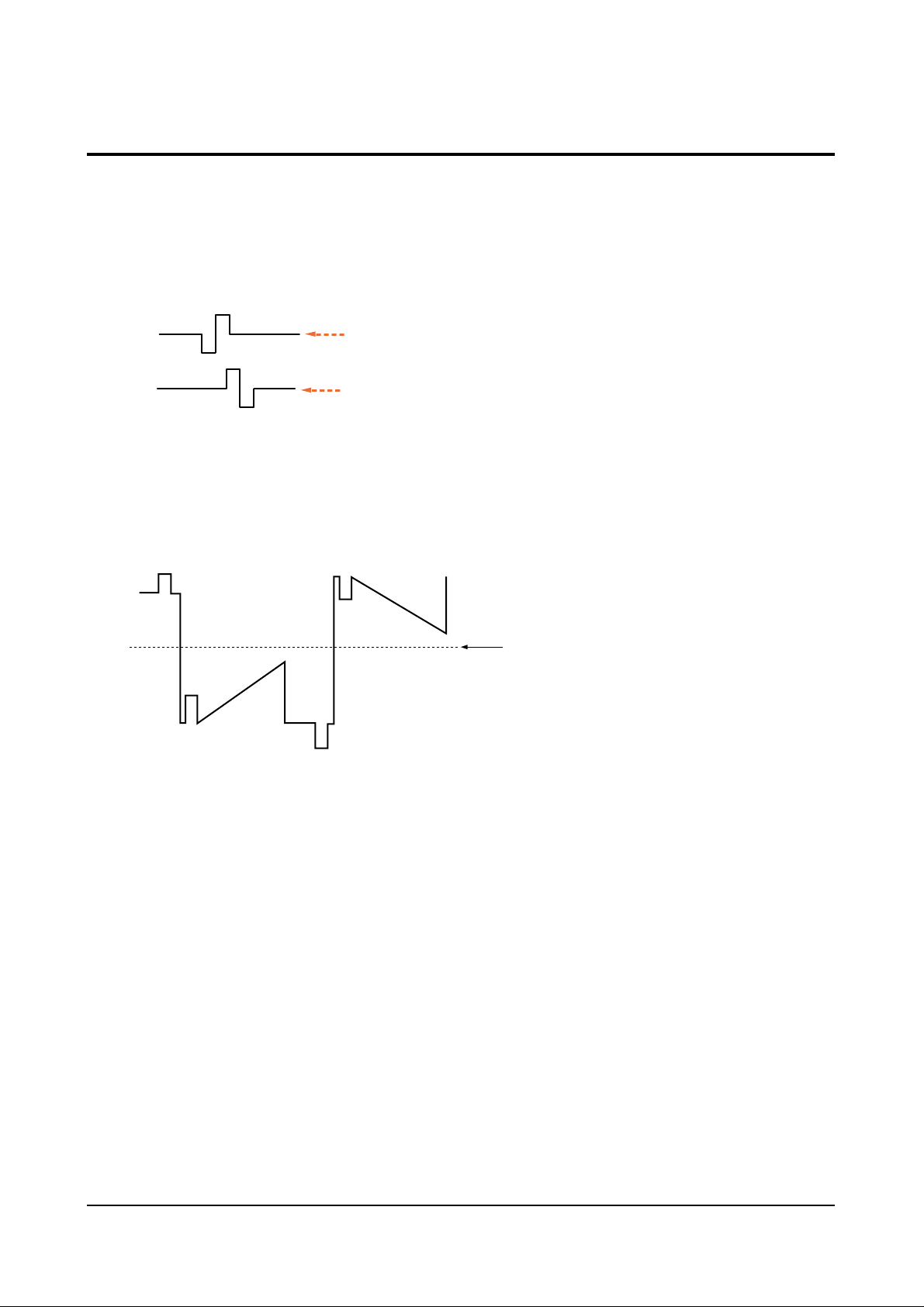
5-6-1 LCD Control Board PLL Adjustment (CNL06)
1. Input a color bar signal.
2. Connect RPD,FPD to an oscilloscope, and check the waveforms (1V/div, 20 µs /div).
5-6-2 Signal Center Adjustment
1. Input a 5-STEP or 7-STEP signal (COLOR OFF).
2. Connect TPL304 (G1) to an oscilloscope, and check the waveforms (2V/div,10µs /div).
5-6-3 Common Voltage Adjustment
1. Connect CNL08 (COMMON) to an oscilloscope (1V/div, 10 µsec/div).
2. Set the common control (#18) to DC 6.8V.
5-6-4 Center Convergence Adjustment
1. Input a lion head pattern from a pattern generator.
2. Adjust the LCD Horizontal/Vertical POS (#24, #25).
5-6-5 SH Position Adjustment
1. Input a lion head pattern from a pattern generator.
2. Adjust the SH position (#26) to balance the position of the sample/hold pulse.
5-6 Circuit Adjustments
RPD
FPD
Adjust so that the DC level
of RPD becomes 2.5V
Adjust so that the DC level of
FPD becomes 2.5V
Adjust the signal center (#19) so that the DC level of the signal center becomes 7V.
center

Alignment and Adjustments
5-10 Samsung Electronics
5-6-6 (C) ADJUSTMENTS
1. Preadjustment
- Input a 10-Step Gray-Scale Pattern.
- Enter the Factory Mode by pressing the TV/VIDEO on the remote control.
2. Sub-bright Adjustment : Adjust so that the value of luminance of the probe
➁
meets the reference coordinate table.
3. Middle White Adjustment : Adjust the factory value of r sub bright, b sub bright
so that the value of the probe
➁ meets the reference coordinate table.
4. High White Adjustment : Adjust the factory value of r sub contrast, b sub contrast
so that the probe
➂ meets the reference coordinate table.
5. Low White Adjustment : Adjust the factory value of
γ ctrl1 so that the value
of luminance of the probe
① meets the reference coordinate table.
6. Low White Adjustment : Adjust the factory value of r
γ ctrl1, b γ ctrl1 so that the
value of the probe
① meets the reference coordinate table.
7. Check that the measurement value of the probe
①,➁,➂ meets the reference coordinate
table (see above). Otherwise, re-do the white balance adjustments.
5-6-6 White Balance Adjustment
5-6-6 (A) REFERENCE COORDINATE TABLE
5-6-6 (B) POSITION OF MEASUREMENT PROBE
Special Notes:
- When the value of the Middle White does not meet the Reference Coordinate Table,
adjust after selecting the factory value of r,b main bright.
- Adjust the CA100 Probe after calibrating it.
- Use a Shibasoku Pattern Generator (10-Step Pattern Generator).
100mm
1
2 3 4 5 6 7 8 9 10
1Probe
2Probe
3Probe
10-sept signal input
W/B Spec
CA-100
Diffusion F ilter Used
yxY
H/L 270 261
7.0
M/L 273 250
L/L 275
260
±
±
±
0.5
0.5
1.5
0.20 0.03
 Loading...