

Samsung SIR-T165 User Manual

Samsung Electronics America inc.
SERVICE DIVISION
400 Valley Road, Suite 201
Mount Arlington, NJ 07856
TEL: 1-800-SAMSUNG (1-800-726-7864)
SIR-T165
................................................................................................................
.............
DIGITAL TV SET TOP BOX
Owner’s
MD68-00278A(ENG)
Instructions
Warning! Important Safety Instructions
CAUTION
RISK OF ELECTRIC SHOCK
DO NOT OPEN
CAUTION: TO REDUCE THE RISK OF ELECTRIC SHOCK, DO NOT REMOVE COVER
(OR BACK). NO USER SERVICEABLE PARTS INSIDE. REFER SERVICING TO QUALIFIED
SERVICE PERSONNEL.
This symbol indicates high voltage is present inside. It is
dangerous to make any kind of contact with any inside part of this
product.
This symbol alerts you that important literature concerning operation
and maintenance has been included with this product.
Note to CATV system installer: This reminder is provided to call CATV system
installer’s attention to Article 820-40 of the National Electrical Code (Section 54 of
Canadian Electrical Code, Part I), that provides guidelines for proper grounding and, in
particular, specifies that the cable ground shall be connected to the grounding system of
the building as close to the point of cable entry as practical.
Caution: FCC regulations state that any unauthorized changes or modifications to this
equipment may void the user’s authority to operate it.
Caution: To prevent electric shock, match the wide blade of plug to the wide slot, and
fully insert the plug.
Attention: pour eviter les chocs electriques, introduire la lame le plus large de la fiche
dans la borne correspondante de la prise et pousser jusqu’au fond.
Important: One Federal Court has held that unauthorized recording of
copyrighted TV programs is an infringement of U.S. copyright laws.
Certain Canadian programs may also be copyrighted and any unauthorized recording
in whole or in part may be in violation of these rights.
Warning-To prevent damage which may result in fire or electric shock
hazard, do not expose this appliance to rain or moisture.

Thank You for Choosing Samsung
Thank you for choosing Samsung! Your new Samsung Digital TV receiver represents the latest in DTV
IRD technology. We designed it with easy-to-use on-screen menus and closed captioning capabilities,
making it one of the best products in its class. We are proud to offer you a product that will provide
convenient, dependable service and enjoyment for years to come.
Important Safety Information
Always be careful when using your product. To reduce the risk of fire, electrical shock, and other
injuries, keep these safety precautions in mind when installing, using, and
maintaining your machine.
• Read all safety and operating instructions before operating your product.
• Keep the safety and operating instructions for future reference.
• Heed all warnings on the product receiver and in the operating instructions.
• Follow all operating and use instructions.
• Unplug the product from the wall outlet before cleaning. Use a damp cloth; do not use liquid or
aerosol cleaners.
• Never add any attachments and/or equipment without approval of the manufacturer. Such additions can increase the risk of fire, electric shock, or other personal injury.
• Do not use the product where contact with or immersion in water is a possibility, such as near
bath tubs, sinks, washing machines, swimming pools, etc.
• Do not place the product on an unstable cart, stand, tripod, bracket,
or table where it can fall. A falling product can cause serious injury to
a child or adult, and serious damage to the appliance. Use only with
a cart, stand, tripod, bracket, or table recommended by the manufacturer or sold with the product. Follow the manufacturer’s instructions
when mounting the unit, and use a mounting accessory recommended
by the manufacturer. Move the product and cart with care. Quick
stops, excessive force, and uneven surfaces can make the unit and
cart unsteady and likely to overturn.
• Provide ventilation for the product. The unit is designed with slots in the cabinet for ventilation to
protect it from overheating. Do not block these openings with any object, and do not place the
product on a bed, sofa, rug, or other similar surface. Do not place it near a radiator or heat register. If you place the product on a rack or bookcase, ensure that there is adequate ventilation
and that you’ve followed the manufacturer’s instructions for mounting.
• Operate your product only from the type of power source indicated on the marking label. If you
are not sure of the type of power supplied to your home, consult your appliance dealer or local
power company.
• Use only a grounded or polarized outlet. For your safety, this product is equipped with a polarized alternating current line plug having one blade wider than the other. This plug will fit into the
power outlet only one way. If you are unable to insert the plug fully into the outlet, try reversing
the plug. If the plug still does not fit, contact your electrician to replace your outlet.
SAFETY 1
• Protect the power cord. Power supply cords should be routed so that they won’t be walked on or
pinched by objects placed on or against them. Pay particular attention to cords at plugs, convenience receptacles, and the point where they exit from the unit.
• Unplug the product from the wall outlet and disconnect the antenna or cable system during a
lightning storm or when left unattended and unused for long periods of time. This will prevent
damage to the unit due to lightning and power-line surges.
• Avoid overhead power lines. An outside antenna system should not be placed in the vicinity of
overhead power lines or other electric light or power circuits or where it can fall into such power
lines or circuits. When installing an outside antenna system, be extremely careful to keep from
touching the power lines or circuits. Contact with such lines can be fatal.
• Do not overload the wall outlet or extension cords. Overloading can result in fire or electric
shock.
• Do not insert anything through the openings in the unit, where they can touch dangerous voltage
points or damage parts. Never spill liquid of any kind on the product.
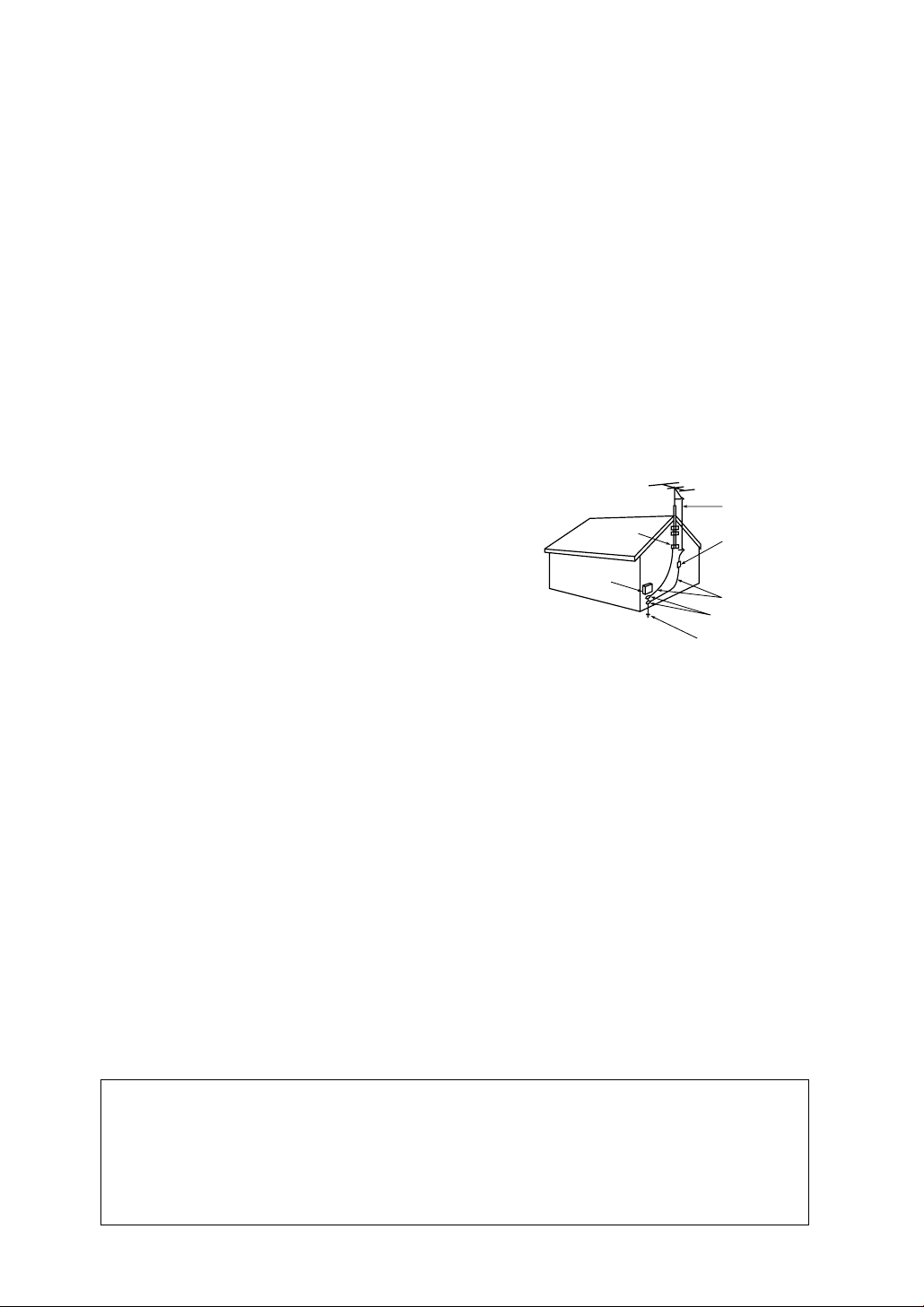
• Ground outdoor antennas. If an outside antenna is connected to the product, be sure the antenna is grounded so
as to provide some protection against voltage surges and
built-up static charges. Section 810 of the National Electrical Code, ANSI/NFPA No.70-1984, provides information about proper grounding of the mast and supporting
structure, grounding of the lead-in wire to an antenna discharge unit, size of grounding conductors, location of
antenna discharge unit, connection to grounding electrodes, and requirements for the grounding electrode.
EXAMPLE OF
ANTENNA GROUNDING
GROUND CLAMP
ELECTRIC
SERVICE
EQUIPMENT
NEC — NATIONAL ELECTRICAL CODE
ANTENNA
LEAD IN WIRE
ANTENNA
DISCHARGE UNIT
(NEC SECTION 810-20)
GROUNDING
CONDUCTORS
(NEC SECTION 810-21)
GROUND CLAMPS
POWER SERVICE GROUNDING
ELECTRODE SYSTEM
(NEC ART 250, PART H)
• Do not attempt to service the product yourself. Refer all servicing to qualified service personnel.
Unplug the unit from the wall outlet and refer servicing to qualified service personnel under the
following conditions:
- when the power-supply cord or plug is damaged
- if liquid has been spilled on the unit or if objects have fallen into the unit
- if the product has been exposed to rain or water
- if the product does not operate normally by following the operating instructions
- if the product has been dropped or the cabinet has been damaged
- when the product exhibits a distinct change in performance
• If you make adjustments yourself, adjust only those controls that are covered by the operating
instructions. Adjusting other controls may result in damage and will often require extensive work
by a qualified technician to restore the product to normal.
• When replacement parts are required, be sure the service technician uses replacement parts
specified by the manufacturer or those that have the same characteristics as the original part.
Unauthorized substitutions may result in additional damage to the unit.
• Upon completion of any service or repairs to this product, ask the service technician to
perform safety checks to determine that the product is in a safe operating condition.
This device complies with part 15 of the FCC Rules. Operation is subject to the following two
conditions:
(1) This device may not cause harmful interference, and
(2) This device must accept any interference that may cause undesired operation.
This television receiver provides display of television closed captioning in accordance with
2SAFETY
§15.119 of the FCC rules.

A Guide to Digital TV
What is Digital Television?
Digital television (DTV) is a new way of transmitting high quality video and audio to your
TV set. Using DTV, broadcasters can transmit high definition TV (HDTV) images, Dolby digital surround audio, and new services such as multicasting (transmitting more than one program on the same TV channel) and datacasting (providing electronic program guides and
interactive television). Several of these services can be combined into a single digital
broadcast.
Digital Television Services
Digital Picture Quality
DTV programs are transmitted in two different formats. The first is Standard Definition
Television (SDTV) and the second is High Definition Television (HDTV).
SDTV program formats include 480-line interlaced (480i) and 480-line progressive (480p)
video. 480i programs are essentially a digital version of our current analog TV programs,
while the 480p format offers improved image detail over 480i. Some 480p programs are
broadcast in widescreen and are comparable to progressive-scan DVD movies in image
quality.
HDTV program formats include 1080-line interlaced (1080i) and 720-line progressive
(720p). Both HDTV formats are always broadcast in widescreen, and both offer much
higher picture quality than SDTV.
Dolby Surround Sound
With DTV, you can listen to a variety of Dolby digital audio formats from Dolby Surround
2.0 to Dolby Digital 5.1 surround, using your home audio system. Many HDTV programs
are now broadcast with DD 5.1 soundtracks.
Interactive Communications and Datacasting
DTV will allow you to interact with your television; choosing programs from a detailed program guide, ordering products on-line while watching TV, and accessing ancillary data
about a program.
A GUIDE TO DIGITAL TV 1

How to View Digital Television
There are three ways to watch DTV. The first is to use an integrated digital TV; one with a
built-in digital television tuner. The second is to connect an external DTV set-top receiver to
a DTV-ready television or monitor. This type of TV or monitor will have wideband component video and stereo audio inputs. You can also watch DTV signals with personal computer (PC) tuner cards and computer monitors.
1. Integrated TVs versus DTV-ready TVs and monitors
The advantage of an integrated DTV set is that it can tune both analog and digital TV channels at the same time. All you'll need to do is add an external antenna and you are ready
to watch DTV.
However, integrated DTV sets are not as common as DTV-ready TVs and monitors. If you
already own a DTV-ready TV with component video inputs, you can enjoy DTV broadcasts
by simply adding a low-cost DTV set-top receiver and antenna.
2. Using your existing analog TV set
Your analog TV set can be used to view down-converted DTV broadcasts by connecting the
DTV set-top receiver to your composite (yellow RCA jack) or S-video (black circular jack)
AV inputs, as well as connecting stereo audio inputs. While the picture quality won't be as
good as you'd see on a DTV-ready TV set, it will be as good or slightly better than analog
TV broadcasts.
3. Using a personal computer and monitor
There are plug-in cards available that will receive and display DTV broadcasts on your
computer monitor. In addition, many computer monitors will display one or more of the
DTV program formats directly. The most compatible format is 480p, which is similar to the
VGA (640x480 pixel) computer display standard. You may be able to watch DTV broadcasts by connecting a computer monitor to the 15-pin jack on the rear of the set-top DTV
receiver.
NOTE
This television receiver supports the copy protection system regulated by DTLA (Digital Transmission
Licensing Administrator). It should be noted that copy protected content may not be viewable
depending on particular connections. For details, please see page 1.11.
2 A GUIDE TO DIGITAL TV

Q&A
1. Is the antenna I use for existing TV reception good enough for DTV?
Over-the-air (OTA) digital TV broadcasting uses the same channels as analog TV and
works well with many existing TV antennas. However, DTV broadcast channel assignments
are different than analog channels. You should find out whether your local DTV broadcasts
are on VHF (channels 2-13) or UHF (channels 14-69) to see if you need a different antenna.
If your DTV channels are on UHF and you already get good UHF reception, your present
antenna may work fine. The same holds true for VHF DTV reception. Note that in some
markets, both VHF and UHF channels are used for DTV broadcasts.
You can find out the latest DTV channel assignments for your area by browsing selected
Internet web sites such as www.titantv.com , www.10000watts.com, and www.fcc.gov.
2. How difficult is it to receive DTV signals indoors?
This depends on whether your local DTV stations are running full power or not and how
close your location is to the transmission tower. DTV receivers do not require as much signal as analog TV receivers to produce high-quality images and sound.
Once the DTV signal level exceeds a certain threshold at the receiver, the digital video and
audio data is decoded at the same quality it was originally encoded for broadcast. This is
a big advantage for DTV over analog TV - there is no noise, ghosting, static, or scratchy
audio.
3. How can I connect an antenna in my townhouse, co-operative apartment, condominium,
or apartment?
The Federal Communications Commission's OTARD Rule (part of the Telecommunications
Act of 1996) allows residents of condominiums, townhouse, or members of neighborhood
associations to put up outside antennas for reception of broadcast TV signals as long as
those antennas are not located in common areas and are no more than 12' in height.
Residents of rental units (apartments, etc) are not covered by the OTARD rules and will
have to use indoor antennas to receive DTV broadcasts. It is possible that the landlord of
an apartment complex can provide broadcast DTV signals via a master TV antenna system
to each apartment.
A GUIDE TO DIGITAL TV 3

Q&A
4. Can I connect my DTV set-top receiver to my cable TV service?
Cable TV systems use a different method for transmitting digital TV programs that is currently incompatible with broadcast DTV set-top receivers. So you will still need to use an outdoor or indoor antenna to receive OTA broadcast DTV programs.
The good news is that you won't have to pay a monthly or per-program charge to watch
OTA DTV and HDTV programs. They're free, unlike subscription satellite TV or premium
cable TV. All you need is an antenna and a DTV set-top receiver to enjoy clear, sharp
widescreen images and high-quality audio.
4 A GUIDE TO DIGITAL TV

CONTENTS
Chapter 1: Connecting the Set Top Box . . . . . . . . . . . . . . . . . . . . . . . . . . . . . . . . . . . . . . . . . .1.1
Front Panel Controls and LEDs . . . . . . . . . . . . . . . . . . . . . . . . . . . .1.1
Rear Panel Jacks . . . . . . . . . . . . . . . . . . . . . . . . . . . . . . . . . . . . .1.2
Connecting Antennas . . . . . . . . . . . . . . . . . . . . . . . . . . . . . . . . . .1.3
Connecting the Set-Top Box to a TV set . . . . . . . . . . . . . . . . . . . . .1.4
Connecting the Set-Top Box to a Computer Monitor . . . . . . . . . . . .1.6
Connecting Video Component . . . . . . . . . . . . . . . . . . . . . . . . . . .1.6
Connecting Audio Component . . . . . . . . . . . . . . . . . . . . . . . . . . .1.8
Connecting the Set-Top Box to a Device with DVI jack . . . . . . . . . . .1.9
Connecting an D-VHS device . . . . . . . . . . . . . . . . . . . . . . . . . . .1.10
Important Notes About Copy Protection . . . . . . . . . . . . . . . . . . . .1.11
Chapter 2: Remote Control and On-Screen Menus . . . . . . . . . . . . . . . . . . . . . . . . . . . . . . . . .2.1
Reviewing the Remote Control . . . . . . . . . . . . . . . . . . . . . . . . . . . .2.1
Installing the Batteries . . . . . . . . . . . . . . . . . . . . . . . . . . . . . . . . . .2.3
Programming the Remote Control . . . . . . . . . . . . . . . . . . . . . . . . .2.3
The On-Screen Menu System . . . . . . . . . . . . . . . . . . . . . . . . . . . .2.4
Using the On-screen Help . . . . . . . . . . . . . . . . . . . . . . . . . . . . . . .2.5
Viewing the Information . . . . . . . . . . . . . . . . . . . . . . . . . . . . . . . .2.6
Chapter 3: Operation . . . . . . . . . . . . . . . . . . . . . . . . . . . . . . . . . . . . . . . . . . . . . . . . . . . . . .3.1
Memorizing Channels . . . . . . . . . . . . . . . . . . . . . . . . . . . . . . . . .3.1
Adding and Deleting Channels . . . . . . . . . . . . . . . . . . . . . . . . . . .3.2
Changing Channels . . . . . . . . . . . . . . . . . . . . . . . . . . . . . . . . . . .3.3
Setting Your Favorite Channels . . . . . . . . . . . . . . . . . . . . . . . . . . .3.4
Fine Tuning Analog Channels . . . . . . . . . . . . . . . . . . . . . . . . . . . .3.5
Checking the Digital-Signal Strength . . . . . . . . . . . . . . . . . . . . . . .3.6
CONTENTS 1

CONTENTS
Setting the Time and Date . . . . . . . . . . . . . . . . . . . . . . . . . . . . . . .3.7
Chapter 4: Special Features . . . . . . . . . . . . . . . . . . . . . . . . . . . . . . . . . . . . . . . . . . . . . . . . . .4.1
Changing the Screen Format . . . . . . . . . . . . . . . . . . . . . . . . . . . .4.1
Choosing a Sound “Multitrack”
(When a Digital Signal is received) . . . . . . . . . . . . . . . . . . . . . . .4.4
Choosing a Sound “Multitrack”
(When an Analog Signal is received) . . . . . . . . . . . . . . . . . . . . . .4.5
Choosing a Digital Sound Format (Dolby or PCM) . . . . . . . . . . . . .4.6
Using Dynamic Range Compression (DRC) . . . . . . . . . . . . . . . . . .4.7
Setting Up Digital Captions (On-Screen Text Messages) . . . . . . . . . .4.8
Setting Up Analog Captions (On-Screen Text Messages) . . . . . . . . .4.9
Rating Control Menu . . . . . . . . . . . . . . . . . . . . . . . . . . . . . . . . .4.10
How to Lock Programs Using the TV (FCC)
Ratings or MPAA Ratings . . . . . . . . . . . . . . . . . . . . . . . . . . . . . .4.11
Important Notes About Parental Locks (“P.Locks”) . . . . . . . . . . . . .4.12
Electronic Program Guide . . . . . . . . . . . . . . . . . . . . . . . . . . . . . .4.13
Using the EPG (Electronic Program Guide) . . . . . . . . . . . . . . . . . .4.14
Viewing Information about One Channel . . . . . . . . . . . . . . . . . . .4.15
Viewing Information about Channels . . . . . . . . . . . . . . . . . . . . . .4.16
Timer Recording . . . . . . . . . . . . . . . . . . . . . . . . . . . . . . . . . . . . .4.17
Controlling FireWire devices . . . . . . . . . . . . . . . . . . . . . . . . . . . .4.18
Programming the Remote Control for Other Components . . . . . . .4.19
CONTENTS 2
Appendix . . . . . . . . . . . . . . . . . . . . . . . . . . . . . . . . . . . . . . . . . . . . . . . . . . . . . . . . . . . . . . . .A.1
Troubleshooting . . . . . . . . . . . . . . . . . . . . . . . . . . . . . . . . . . . . . .A.1
Care and Maintenance . . . . . . . . . . . . . . . . . . . . . . . . . . . . . . . .A.3
Specifications . . . . . . . . . . . . . . . . . . . . . . . . . . . . . . . . . . . . . . .A.4
Manufactured under license from Dolby Laboratories.
“Dolby” and the double-D symbol are trademarks of Dolby Laboratories.
1
1
CHAPTER ONE
Connecting The Set T op Box
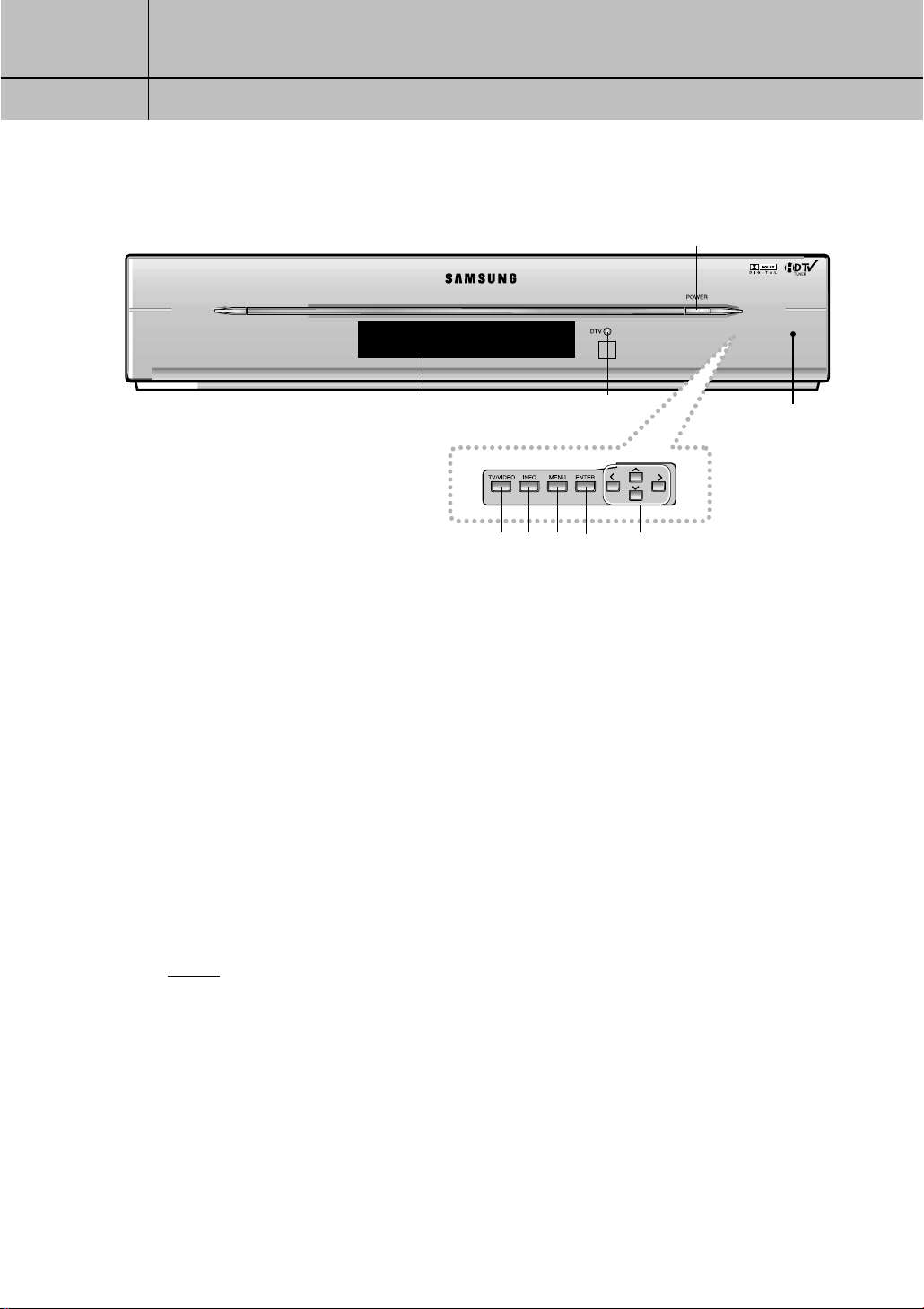
Front Panel Controls and LEDs
Œ
ΠPOWER
Press to turn the power on or off.
´ DTV (LED)
When a digital signal is received, the LED indicator
lights up Green.
ˇ TV/VIDEO
Press to select another source (STB, VCR, CATV, or DVD).
¨ INFO
Press to display information about the current box
settings and program:
Channel number, Time, Program title, Program
duration, Caption, Rating control, Digital picture grade,
and MTS language.
”
´
ˆ¨∏Øˇ
ˆ MENU
Press to display the on-screen menus.
Ø ENTER
Press to activate a selection when using the on-screen
menus.
∏ Menu Up/Down/Left/Right
Use to change channels or to move highlight
(when using the on-screen menus).
” Display
Displays the current status of video, audio and source.
Pull and open the
cover to use front
panel controls.
NOTES
In this instruction book, the terms “Set-Top Box” and “DTV” are equivalent.
Both terms appear in this instruction book, on the remote control markings, and on the
On-Screen display.
1.1
1
1
CHAPTER ONE
Connecting The Set T op Box
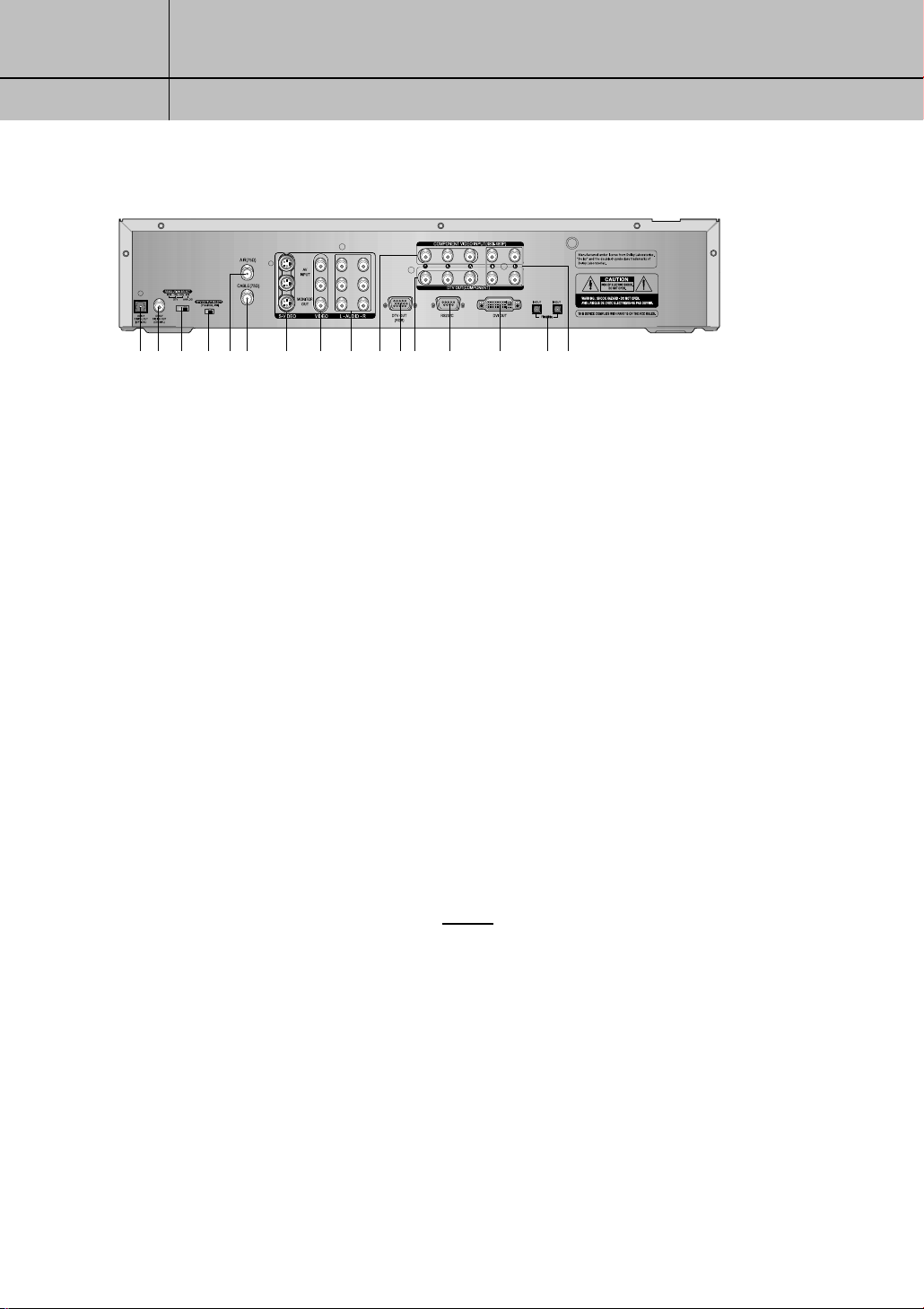
Rear Panel Jacks
Œ´ ˇ ¨ ˆØ ∏ ” ’ ˝ Ô Ò Ú Æı
ΠDOLBY DIGITAL OUT (OPTICAL)
Use to connect the Digital Audio Input of your TV or audio
component.
´ DOLBY DIGITAL OUT (COAXIAL)
Use to connect the Digital Audio Input of your TV.
ˇ RESOLUTION SELECT SWITCH
Switches between 1080i (interlaced scanning), 720p
(progressive scanning), 480p (progressive scanning),
and 480i (interlaced scanning) formats. Switches
the DTV OUT (YP
• 1080i (Interlaced Scanning)
Use this setting for an HDTV Ready 16X9 (wide screen)
aspect ratio TV monitor with HDTV ready component
video inputs that can handle the 1080i video output format.
• 720p (Progressive Scanning)
Use this setting for an HDTV Ready 16X9 (wide screen)
aspect ratio TV monitor with HDTV ready component
video inputs that can handle the 720p video output format.
• 480p (Progressive Scanning)
Use this setting for a Digital Ready 4X3 aspect ratio TV
monitor with Progressive Scanning DTV ready component video inputs that can handle the 480p video output
format. The TV monitor may be labeled Enhanced Definition or Progressive Scanning, but not Wide Screen.
• 480i (Interlaced Scanning)
Use this setting for a conventional TV with regular video,
S-Video, or component video inputs.
¨ DTV OUT SELECT
Use to select YPBPR/RGB,DVI according to the video output
from the TV or monitor.
ˆ RF (AIR) INPUT
Connect the Air antenna here.
BPR
/RGB) to the following formats:
Ø RF (CABLE) INPUT
Connect the CATV cable here.
∏ S-VIDEO INPUT/OUTPUT
Provides good picture quality. If your TV or monitor has SVideo capability, use this jack along with the Audio/Video
jacks to connect the Set-Top Box. Use this output for conventional TV sets that have an S-Video input but no component video inputs.
” VIDEO INPUT/OUTPUT
The two jacks on top are for VIDEO INPUT and the one on
the bottom is for MONITOR (VIDEO OUTPUT). These jacks
should be used for an ordinary TV not having S-Video or
Component Video Input/Output.
’ AUDIO INPUT/OUTPUT
The two sets of jacks on top are for AUDIO INPUT and the
one set on the bottom is for MONITOR (AUDIO OUTPUT).
˝ COMPONENT VIDEO INPUT (YPBPRformat)
Use to input 480i/480p video source.
NOTES
The use of 1080i on a 4X3 monitor or
the use of 480p on a 16X9 monitor may
cause aspect ratio picture distortion.
720p will only work on selected HDTV
Ready TVs. Check the TV monitor’s
owner’s manual to verify this capability.
480i will only work on conventional TV
sets.
If you turn the switch while the system is
operating, the system will be rebooted.
1.2
1
1
CHAPTER ONE
Connecting The Set T op Box
Ô DTV OUT (RGB format)
You can connect RGB to a TV, computer monitor, or another
video component input. 1080i, 720p, and 480p are available by setting the RESOLUTION SELECT switch.
DTV OUT COMPONENT (YPBPRformat)
You can connect YPBPRto a TV, computer monitor, or another video
component input. As with DTV OUT (RGB format), 1080i, 720p, and
480p are available by setting the RESOLUTION SELECT switch.
Ò RS232C
Used for service.
Ú DVI OUT
Use to connect a device equipped with DVI interface.
DVI OUT supports HDCP function.(See Notes on page 1.9.)
Æ FireWire(IEEE1394) INPUT/OUTPUT
Use to connect external devices (D-VHS, AV-HDD, etc.)
ı L/R ANALOG-AUDIO OUTPUTS
Connect these terminals to the analog audio inputs of a TV set (i.e.,
to a TV that has jacks for L/R inputs). Or, connect these terminals to
the L/R inputs of a separate audio component.
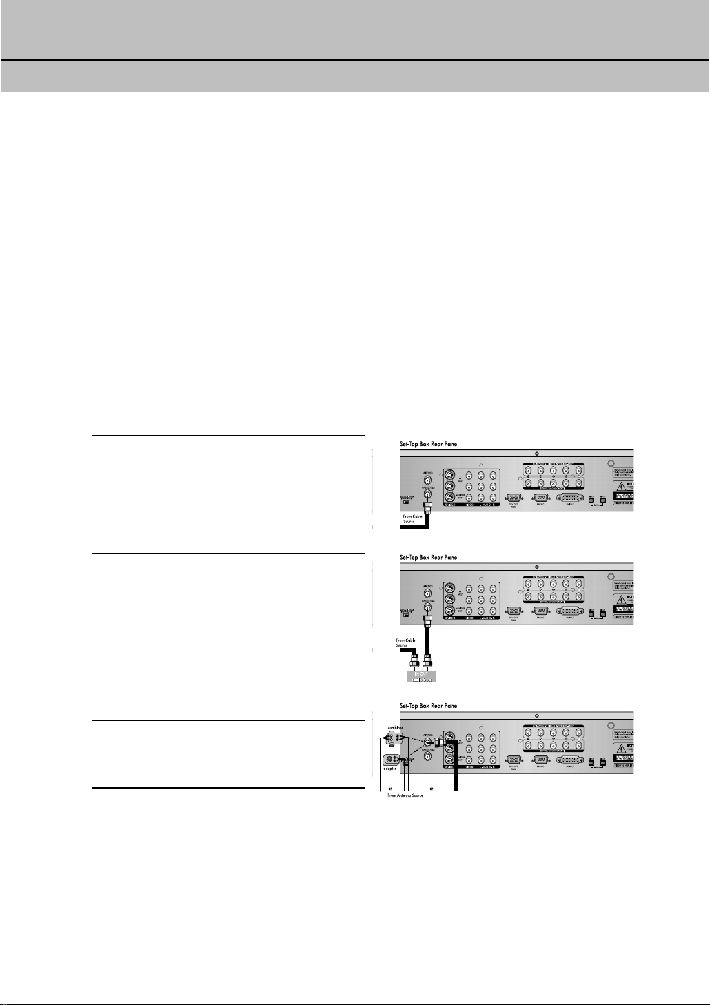
Connecting Antennas
This section shows how to connect a cable TV with or without a cable box, and how to
connect an indoor or outdoor antenna.
Cable TV without a Cable Box: If you
have a cable TV and do not use a cable box,
1
connect the cable to RF (CABLE) INPUT on the
rear of the Set-Top Box.
Cable TV with a Cable Box: If you have
a cable box, connect as shown in the
2
illustration to the right.
If you want to connect a VCR with your cable
box, see the section on how to connect a
VCR with a cable box in page 1.7 .
Indoor/Outdoor Antenna: You may
need a 75Ω adaptor or a combiner, as
3
shown in the illustration right.
NOTES
• If your antenna has separate leads for VHF/UHF signals, you will need to purchase a
combiner and connect it as shown in illustration above.
• The Set-Top Box can receive DTV signals in the event that a local cable provider is passing
8VSB through on their system.
1.3
1
1
CHAPTER ONE
Connecting The Set T op Box
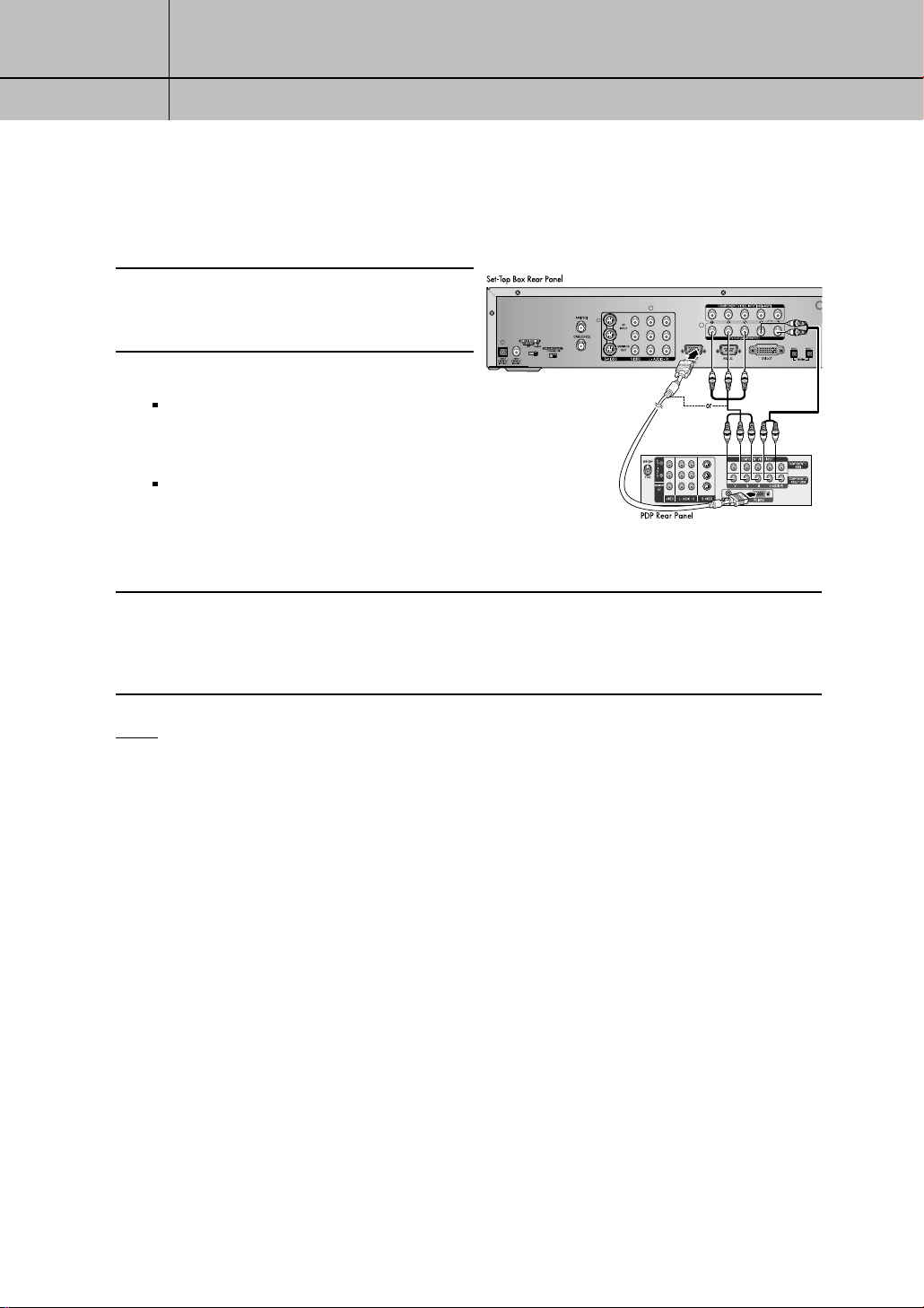
Connecting the Set-Top Box to a TV Set
Plasma Display Panel (PDP)
Connect an antenna cable to the RF input
jacks on the Set-Top Box.
1
Connect the Video Cables.
2
YPBPRformat: Connect a video cable
between the DTV OUT COMPONENT jacks
on the Set-Top Box and the DTV INPUT jacks
on the PDP.
RGB format: Connect a video monitor
cable between the DTV OUT (RGB format)
jack on the Set-Top Box and the RGB VIDEO
IN jack on the PDP.
Connect the Audio Cables
Connect an audio cable between the Lt/Rt AUDIO OUT jacks on the Set-Top Box and the L/R
3
AUDIO IN jacks on the PDP.
NOTE
You must set “DTV OUT SELECT (YPBPR/RGB, DVI)” properly for the PDP INPUT jack.
1.4
1
1
CHAPTER ONE
Connecting The Set T op Box
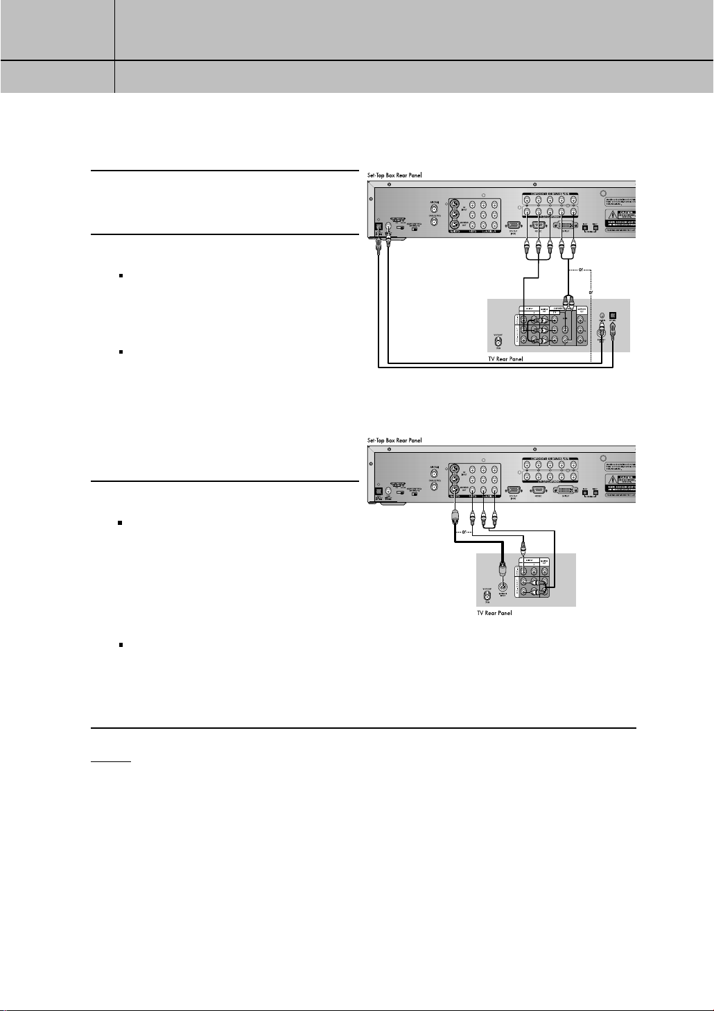
Digital Ready TV or Normal TV
Connect an antenna cable to the RF input
jacks on the SetTop Box.
1
Connect the Video Cables.
2
Digital Ready TV: Connect a video
cable between the DTV OUT COMPONENT (YPBPR) jacks on the Set-Top Box and
the DTV INPUT jacks on the TV.
Normal TV: Connect a video cable
between the VIDEO OUT jack on the SetTop Box and the VIDEO INPUT jack on the
TV. Or, connect an S-Video cable between
the S-VIDEO OUTPUT jack on the Set-Top
Box and the S-VIDEO INPUT jack on the
TV.
<Digital Ready TV>
Connect the Audio Cables
3
Digital Ready TV: Connect an audio
cable between the DOLBY DIGITAL OUT
(optical or coaxial) jack on the Set-Top Box
and the Dolby Digital In jack on the TV.
Or, connect an audio cable between the
Lt/Rt AUDIO OUT jacks on the Set-Top Box
and the L/R AUDIO IN jacks on the TV.
Normal TV: Connect an audio cable
between the L/R AUDIO OUT jacks on the
Set-Top Box and the L/R AUDIO IN jacks
on the TV.
NOTES
•The TV set must be “digital compatible” (i.e., it must have appropriate audio and digital video
terminals).
•If 1080i, 720p, or 480p (DIGITAL) is selected with the RESOLUTION SELECT switch on the Set-Top
Box, the On-Screen Display menus will not be supported for VIDEO OUT and S-VIDEO OUT. The
OSD menus for VIDEO OUT and S-VIDEO OUT are supported only when 480i (ANALOG) is
selected.
•You must set “DTV OUT SELECT (YP
BPR
/RGB, DVI)” for YPBPRinterface.
< Normal TV>
1.5
1
1
CHAPTER ONE
Connecting The Set T op Box
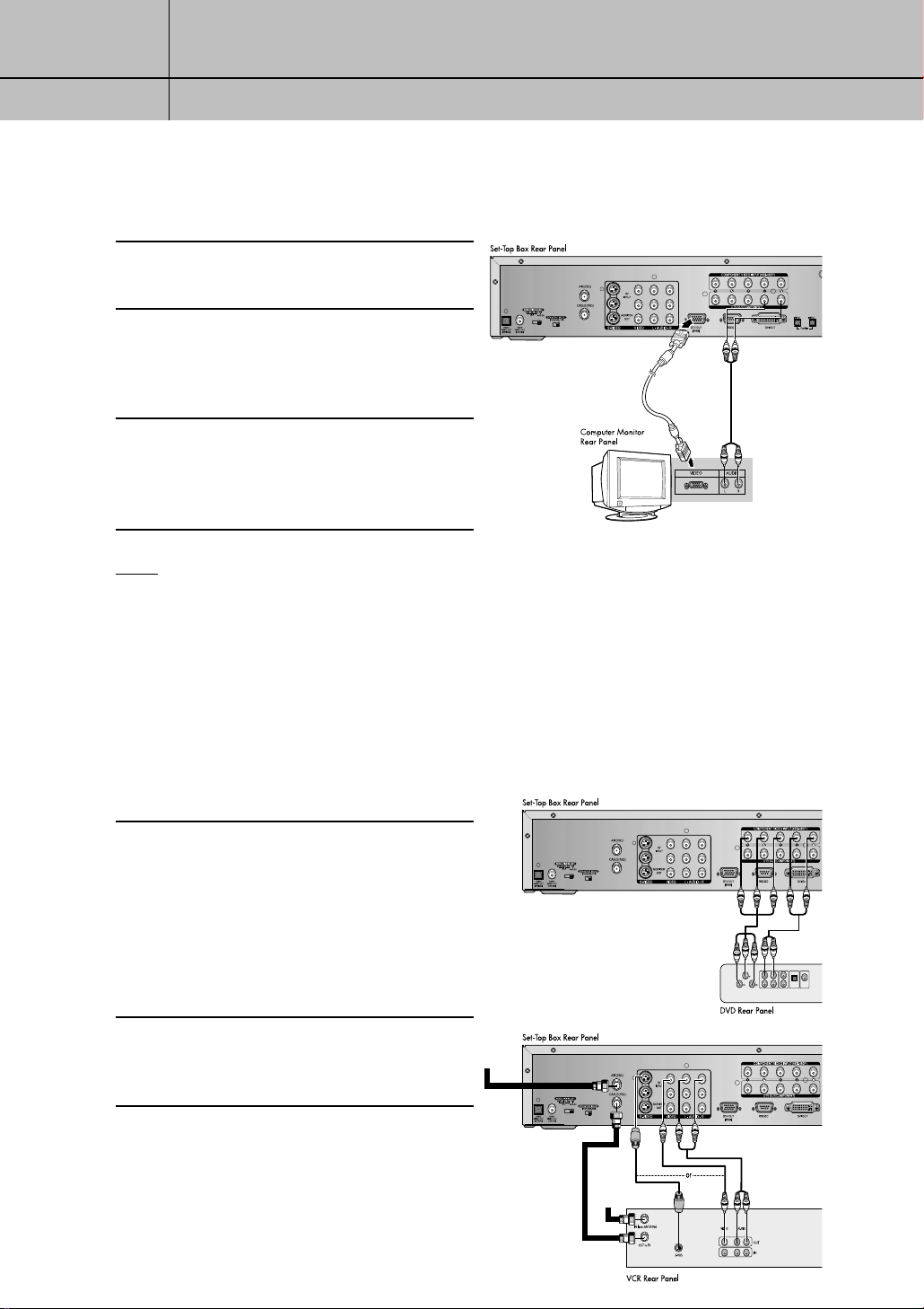
Connecting the Set-Top Box to a Computer Monitor
Connect an antenna cable to the RF input
jacks on the Set-Top Box.
1
Connect a computer video monitor cable
between the DTV OUT (RGB format) jack
2
on the Set-Top Box and the VIDEO IN jack on
the computer monitor.
Connect an audio cable between the
Lt/Rt AUDIO OUT jacks on the Set-Top
3
Box and the L/R AUDIO IN jacks on the
computer monitor.
NOTE
You must set “DTV OUT SELECT (YPBPR/RGB,DVI)” for RGB interface.
Connecting Video Component
This section shows how to connect video components, such as a Digital Video Disc (DVD)
player, a VCR without/with a cable box, a VCR using MONITOR OUT, a laser disc
player, or a camcorder to your Set-Top Box.
Digital Video Disc (DVD) Player
Connect a DVD player to the COMPONENT
1
VIDEO INPUT jacks on the Set-Top Box.
For further information on video connections,
see the owner’s manual for your DVD player.
AUDIO OUT VIDEO OUT DIGITAL
LR
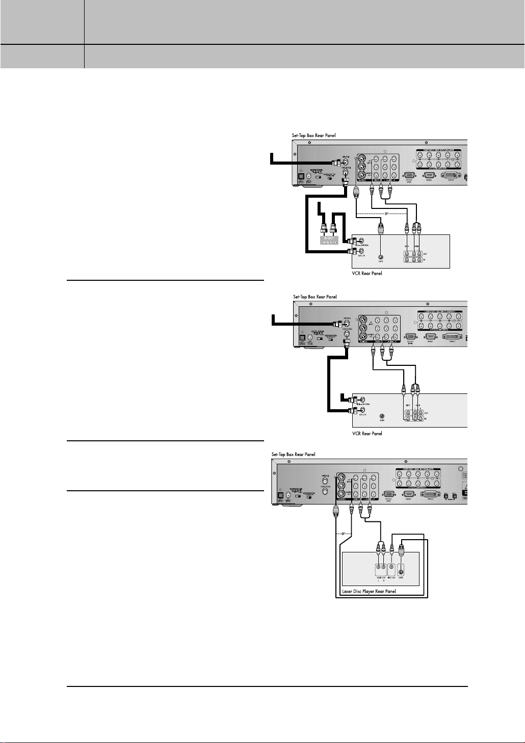
VCR without a Cable Box
Connect a VCR without a cable box to the
2
Set-Top Box, as shown in the illustration right.
From Antenna
Source
DIGITAL
OPTICAL
Audio OUT
Audio OUT
1.6
From Cable
Source
1
1
CHAPTER ONE
Connecting The Set T op Box
VCR with a Cable Box
Connect a VCR with a cable box to the
3
Set-Top Box, as shown in the illustration
right.
VCR with Monitor Out jacks
If you connect a VCR with the MONI-
4
TOR OUT jacks to the Set-Top Box, the VCR
will record exactly what you are viewing on
the Set-Top Box.
From Antenna
Source
From Antenna
Source
From Cable
Source
Laser Disc Player
Connect a laser disc player to the Set-Top
5
Box, as shown in the illustration to the right.
From Cable
Source
1.7
1
1
CHAPTER ONE
Connecting The Set T op Box
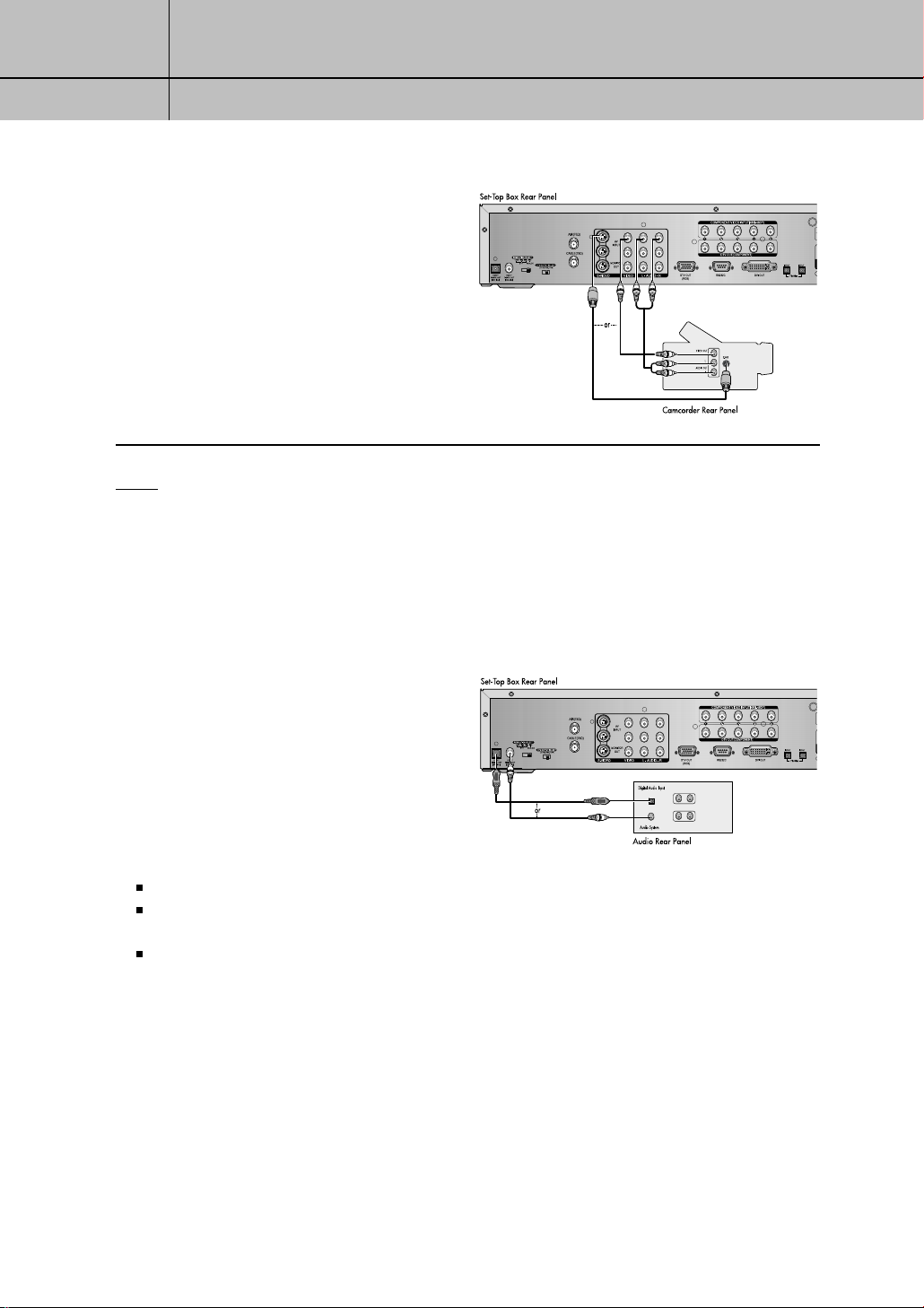
Camcorder
Connect a camcorder to the Set-Top
6
Box, as shown in the illustration to the right.
Connect Audio/Video cables or S-Video
cable between the Set-Top Box and
camcorder.
NOTE
If both S-Video and Video cables are connected, S-Video will override Video.
Connecting an Audio Component
There are many types of audio systems on
the market today.
A simplified illustration of an audio system is
shown to the right. For more information, see
your audio system owner’s manual.
OPTICAL
COAXIAL
If your audio system has :
A coaxial digital audio input, connect the audio system to the DOLBY DIGITAL OUT (COAXIAL) jack on the Set-Top Box.
An optical digital audio input, connect the audio system to the DOLBY DIGITAL OUT (OPTICAL) jack on the Set-Top Box.
Be certainto remove the black cover from the optical output before inserting the cable.
Both coaxial and optical digital audio inputs, SAMSUNG recommends you use the optical digital output.
Do not connect both optical and coaxial cables. This may damage your audio system.
L AUDIO IN R
AUDIO OUT
1.8
1
1
CHAPTER ONE
Connecting The Set T op Box
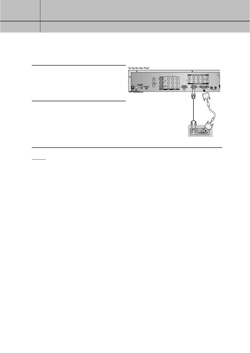
Connecting the Set-Top Box to a Device with a DVI jack
Connect a DVI cable between the
1
2
NOTES
DVI OUT jack on the Set-Top Box
and the DVI IN jack on the DVI device
(TV, monitor).
Connect audio cables between the Lt/Rt
AUDIO OUT jacks on the Set-Top Box
and the L/R AUDIO IN jacks on the DVI
device.
TV Rear Panel
This Set-Top Box supports HDCP technology. HDCP stands for High-bandwidth Digital Content
•
Protection, which provides secure data transmission for high definition video.
Only DVI-HDCP supported devices can be connected.
•
A 25-pin DVI-D jack is used, so only digital signals can be viewed.
•
1.9
 Loading...