

Page 1
Samsung's OMS (Optical Media Solution) Customer Support Website
(Http://samsung-ODD.com) offers the lates t versions of firmware for ODD products,
user instructions and product information.
SH-D162C (TS-H352C)
Select Model
SH-D162C(TS-H352C)
Page 2
g
Index
Connecting the Cables
Main Page
Safety Precautions
Notational
Installation
While Operating
Other
Introduction
Front
Rear
Setup
Installing the DVD-ROM Drive
Connecting the Cables
Installing the Device Driver
Setting Up the Device Driver
Using the Drive
Using the DVD-ROM Drive
Storing and Cleaning Your Discs
Upgrading the Firmware Flash Memory
System Requirements
Troubleshootin
Solving Technical Problems
Specifications
Page 3

Safety Precaution
Connecting the Cables
Warning / Caution
: This symbol indicates explanations about extremely dangerous matters.
Warning
Caution
If users ignore this symbol and handle the device the wrong way, serious injury or death could
result.
: This symbol indicates explanations about dangerous matters.
If users ignore this symbol and handle the device the wrong way, damage to home or property
could result.
Notational
Failure to follow directions noted by this symbol co uld result in bodily harm or damage to
equipment.
Prohibited
Important to read and understand at all times
Do not disassemble
Any change or modification not expressly approved by designated qualified personnel could void your
authority to operate this device.
Always make sure that the disc does not have a crack befo re use. If the disc has a crack (especially
around the center hole), it is recommended to make a copy immed iately and use the copy instead.
When a cracked disc is used continuously, the size of the crack is likely to grow and this will eventually
result in irreparable damage to the disc.
Important to read and understand at all times.
Page 4
A
A
Safety Precaution
Connecting the Cables
Installation
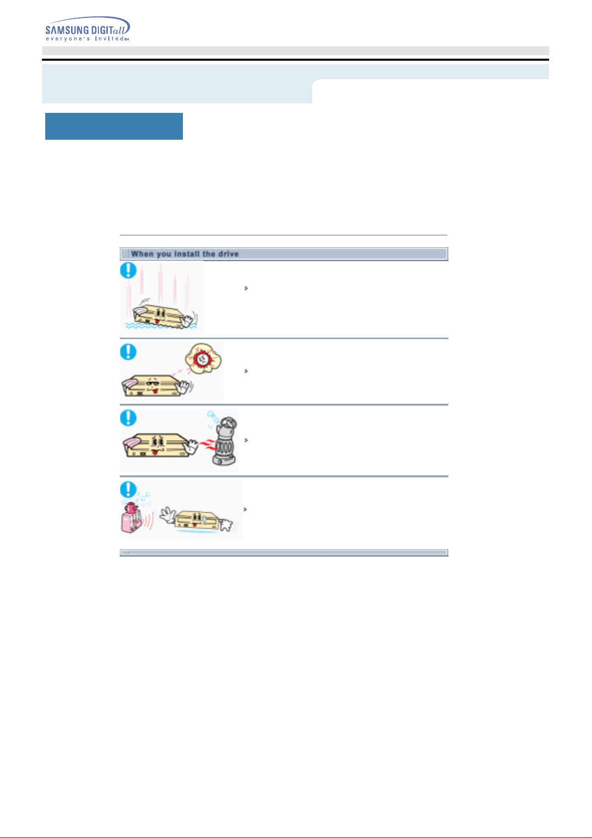
Place the drive on a level surface.
-
Failure to do so may cause the device to fall onto a hard surface,
resulting in damage or malfunction.
Do not place the drive in direct sunlight.
void low- or high-temperature environments.
void high-humidity environments.
Page 5

Safety Precaution
Connecting the Cables
While Operating
Handle with caution to prevent damage from external shock.
Do not drop the drive, and protect it fromsevere shocks.
- It can damage the drive or cause it to malfunction.
Do not move the drive whil e in operation and do not attempt to open
the disc tray byforce.
Make sure to close all working programs before attempting to open the
tray and always usethe open/close button.
- Do not insert a pin into the emergency opening while in operation.
Do not use cracked, distor ted or damaged discs.
- In particular, a disc with a crack on the inner tracks may break while in
use.
Page 6
Safety Precaution
Connecting the Cables
Other
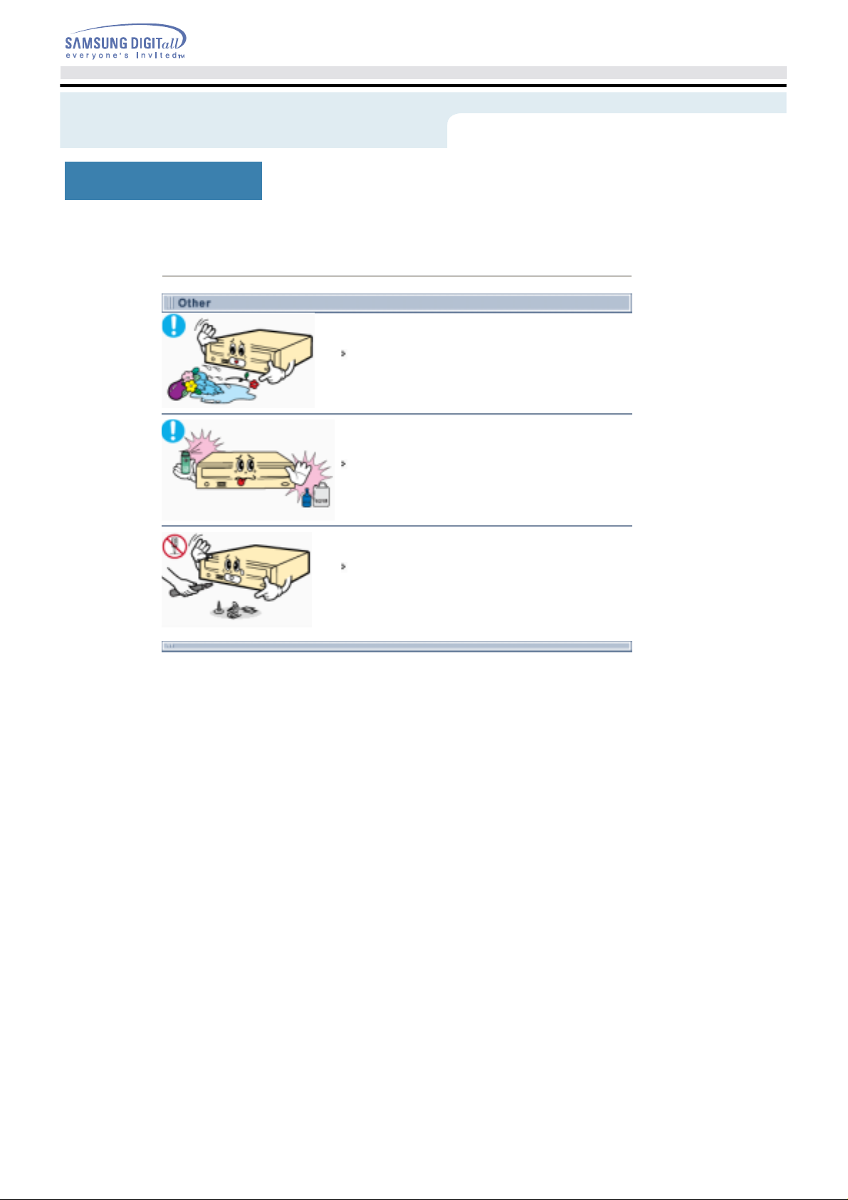
Never allow food particles or foreign substances to enter the drive
casing.
To protect against the risk of fire, do ot spill such liquids as
alcohol and benzene on the drive.
Do not disassemble, attempt to repair or modify the device
without express approval as di rected in the manual.
- To reduce the risk of damage, electric shock, and fire,
Page 7
Introduction
Connecting the Cables
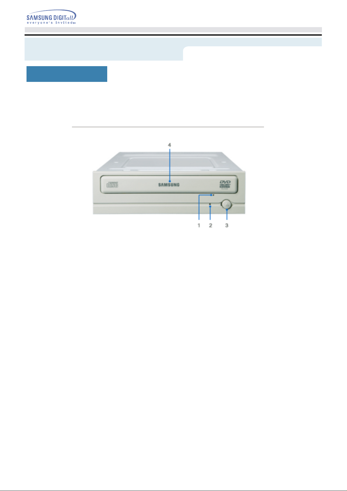
Front
Emergency eject hole. (if the compartment does not open when you press the Eject button, power off the
1.
computer, insert a pin or unfolded paper clip in the hole and push firmly)
Indicator Light. (When it is green, a disc is being read.)
2.
Eject button.
3.
Disc compartment. (the compartment opens and closes automatically when you press the Eje ct button)
4.
Page 8
Introduction
Connecting the Cables
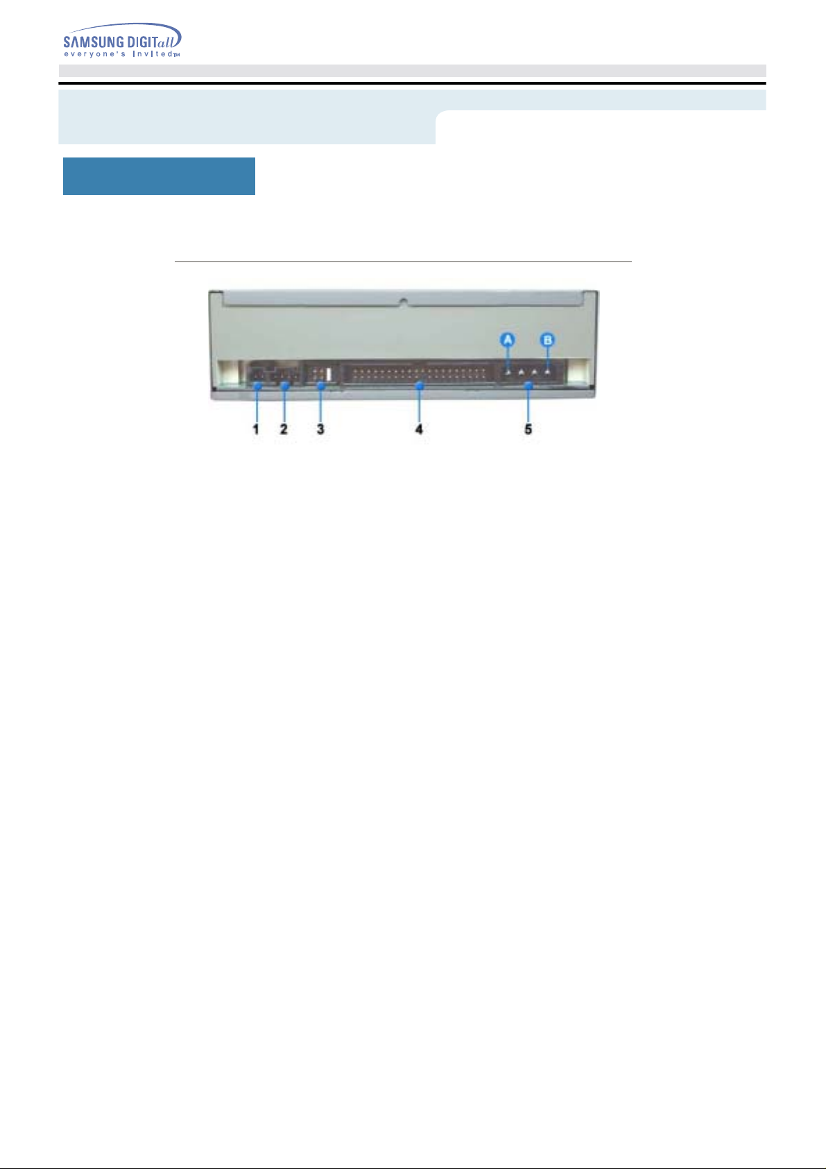
Rear
Two-pin digital audio output terminal for use with a sound or MPEG card supporting digital audio features.
1.
Four-pin sound output terminal for use with a sound card. (refer to the sound card documentation for
2.
further details)
Master/slave select terminal.
3.
40pin host IDE interface connector.
4.
4pin power terminal.
5.
(A : +5V DC)
(B : +12V DC)
Page 9
Setup
Connecting the Cables
Installing the DVD-ROM Drive
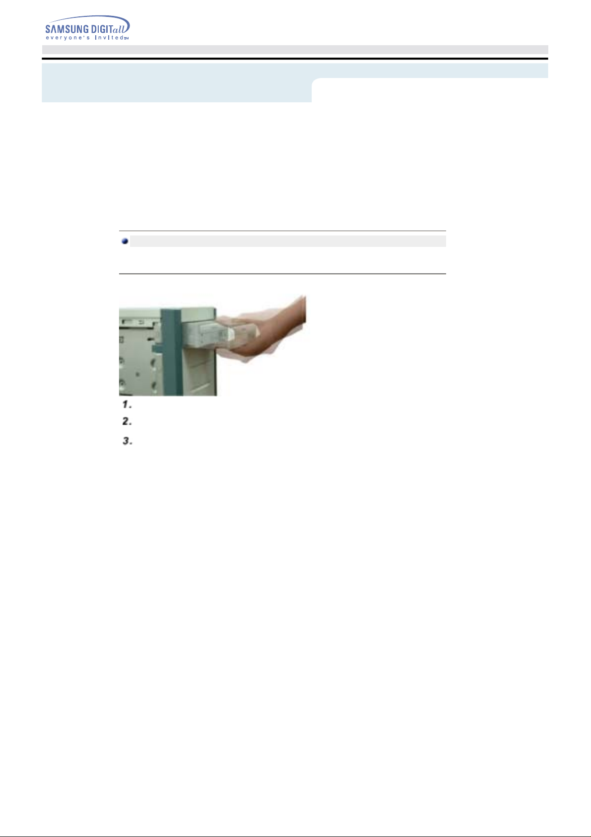
Make sure that the PC is powered off and disconnected from any power source.
If necessary, attach a horizontal bracket to both sid e s of the drive.
Remove the cover from a free expansion slot and install the DVD-ROM drive, as shown in the
illustration.
Page 10
Setup
Connecting the Cables
Connecting the Cables
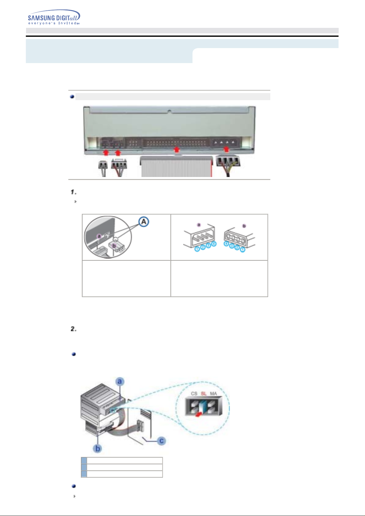
Connecting the power cable
The 4-pin power cable from the internal power unit of your computer must be connected to the power
terminal on the rear of the Optical drive drive.
+5V DC
1
Ground
Cut S-IDE
A -
An improperly connected power c able may cause trouble. Check the direction of the power connector
Note:
and the incline S-IDE of the Optical drive before connecting.
Connecting the E-IDE cable
Insert the E-IDE cable (40-pin), which is connected to the hard disk to the interface terminal.
(Place the red line of the cable close to the Pin 1.)
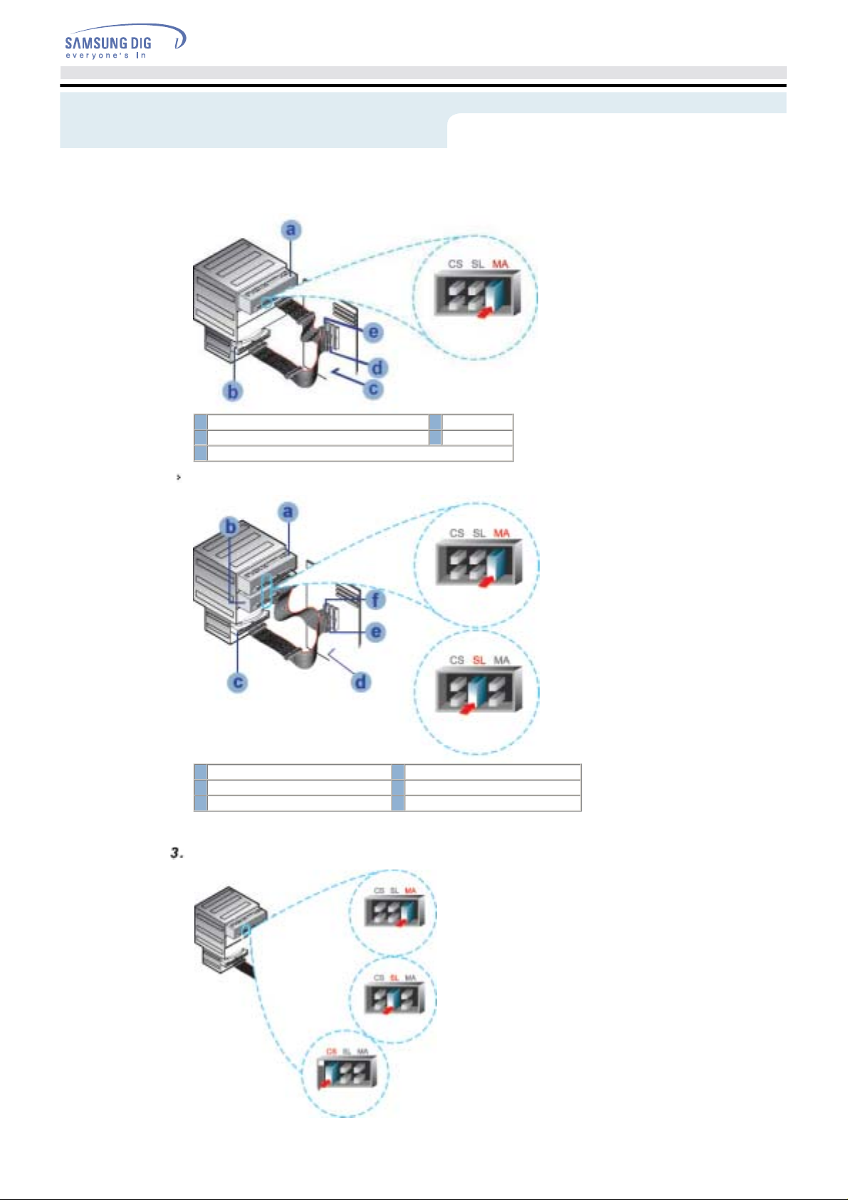
When using one E-IDE cable
Connect the cable to the SL (Slave) of the Master/Slave Select Terminal at the rear of the Optical
drive.
2
Ground
3
+12V DC
4
a : Slave Drive (Choose the SL Jumper)
b : Hard Drive
c : MainBoard
When using two E-IDE cable
If there is only one Optical drive, select MA (Master).
Page 11
Setup
a : Master Drive (Choose the MA Jumper)
c : MainBoard d : Primary 1
e : Secondly 1
If there is two Optical drive, select MA (Master) / SL (Slave).
a : Master Drive (Choose the MA Jumper) b : Slave Drive (Choose the SL Jumper)
c : Hard Drive d : MainBoard
e : Primary 1 f : Secondly 1
b : Hard Drive
Installing a jumper on the master/slave select terminal
Page 12

Setup
Connect a jumper to the rear S-IDE of the Optical drive.
If the jumper is connected to MA (Master), it will work in the Master mode.
If the jumper is connected to SL (Slave), it will work in the Slave mode.
If the jumper is connected to CS (CSEL), you can control the device by using the host interface signal
CSEL. (In general, connection to MA is recommended.)
Connecting the audio cable from a sound card
Connect the 4-pin audio cable between the sound output terminal on the Optical drive and the audio
input terminal on the sound card.
For clearer sound, use a digital output terminal.(Available only for the CARD that supports digital
output) This may not be available for general sound cards.
Page 13
Setup
Installing the Device Driver
This Device Driver is an installation driver that can detect ODD (Optical Disc Drive) products in DOS mode.
It provides only the reading function in Dos mode.
(For recording, it is recommend not to install the Device Driver designed for DOS mode)
The Device Driver for DOS mode is included in the Ddriver or DOS Driver folder of the disc enclo sed with the
product that you purchased.
For Windows98/2000/ME/XP or higher version that uses a device driver provided by Windows,
there is no need to set up an e xtra device driver.
Refer to the steps below to see if Windows detects the drive.
Double-click on the
Double-click on the
Double-click on the
Click on the Device
Expand the CD-ROM branch.
The
Installing the Device Driver
My Computer
Control Panel
System
Manager
icon on your desktop.
folder.
icon.
tab.
device name is displayed.
Page 14
Setup
Setting Up the Device Driver
The device driver is located in the Ddriver folder of the User's Guide disc with is provided in the
package.
This device driver is to recognize a DVD-ROM drive on Dos mode.
This driver should be applied for DOS mode user to install on Windows 98 or Windows ME only.
Automatic Setup
Insert the
Run the
When Setup is successfully completed, click OK button or press the
Reboot the computer.
User's Guide
CDSETUP.EXE
Manual Setup
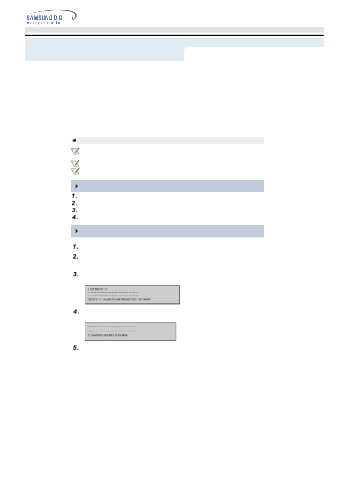
Make the
C:\SAMSUNG
Copy the files from the User's Guide disc to the
To do so, type
Edit the
CONFIG.SYS
Add the
DEVICE=C:\SAMSUNG\SSCDROM.SYS \D:SSCD000/V
disc into the CD-ROM drive and open the
file in the
directory.
COPY D:\Ddriver * . * C:\SAMSUNG
file.
Ddriver
folder.
C:\SAMSUNG
after the
folder.
Ddriver
key.
Enter
directory.
prompt and press [
C:\
entry.
Enter
].
Edit the
Add the
Reboot the computer.
AUTOEXEC.BAT
C:\SAMSUNG\MSCDEX/D:SSCD000
file.
entry.
Page 15
Using the Drive
Connecting the Cables
Using the DVD-ROM Drive
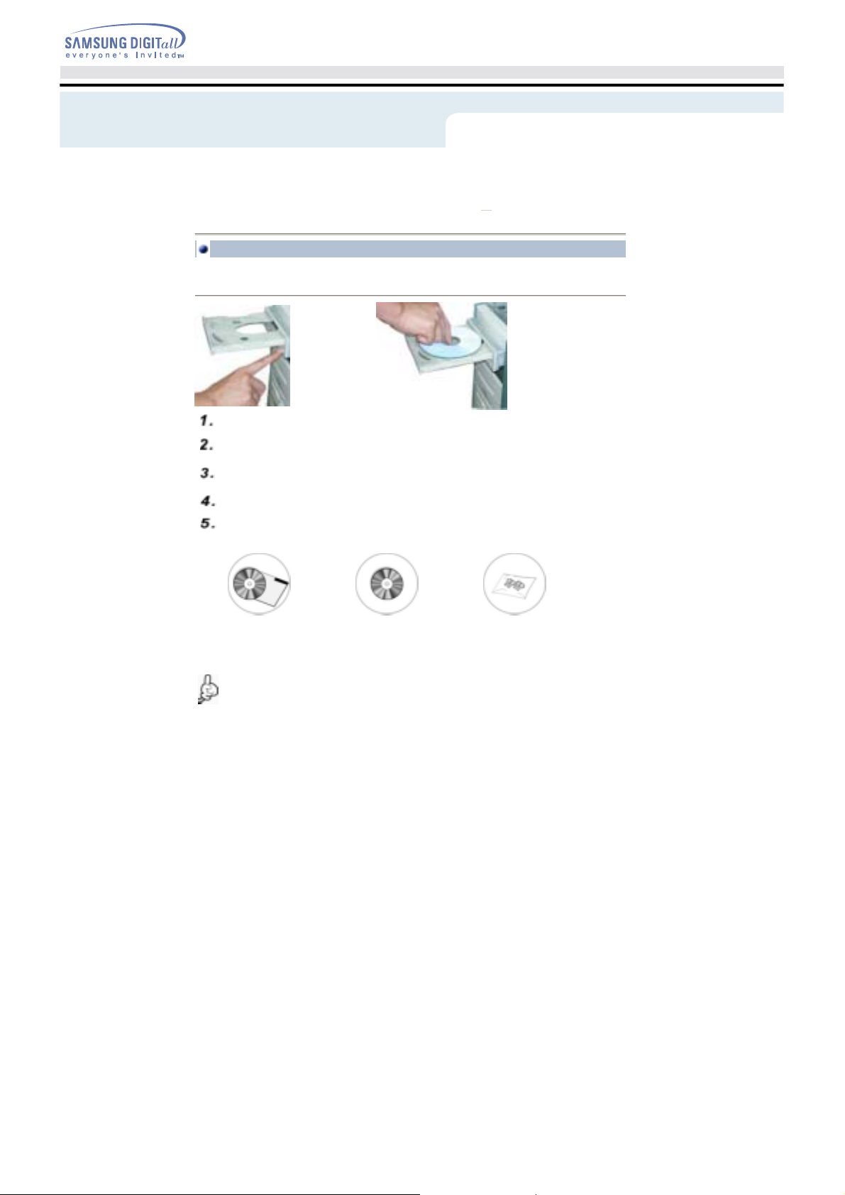
To play audio or video CDs a n d / or DVDs in your DVD-ROM drive, proceed as follows.
Push the power button and boot the computer.
After booting the computer , open the disc compartment by pressing the Eject button.
Insert the disc (CD/DVD) with the label on the disc faci ng upwards and close the disc
compartment by pressing the Eject button. The indicator light comes on.
Play the disc (CD/DVD).
Accessories
The type of accessories varies depending on product mo del.
z
User Manual & Setup Guide. Software. Screws.
Playing Video CDs
Set up and run the SOFT MPEG program.
Design and specifications are subject to change without prior notice.
Page 16
Using the Drive
Connecting the Cables
Storing and Cleaning Your Discs
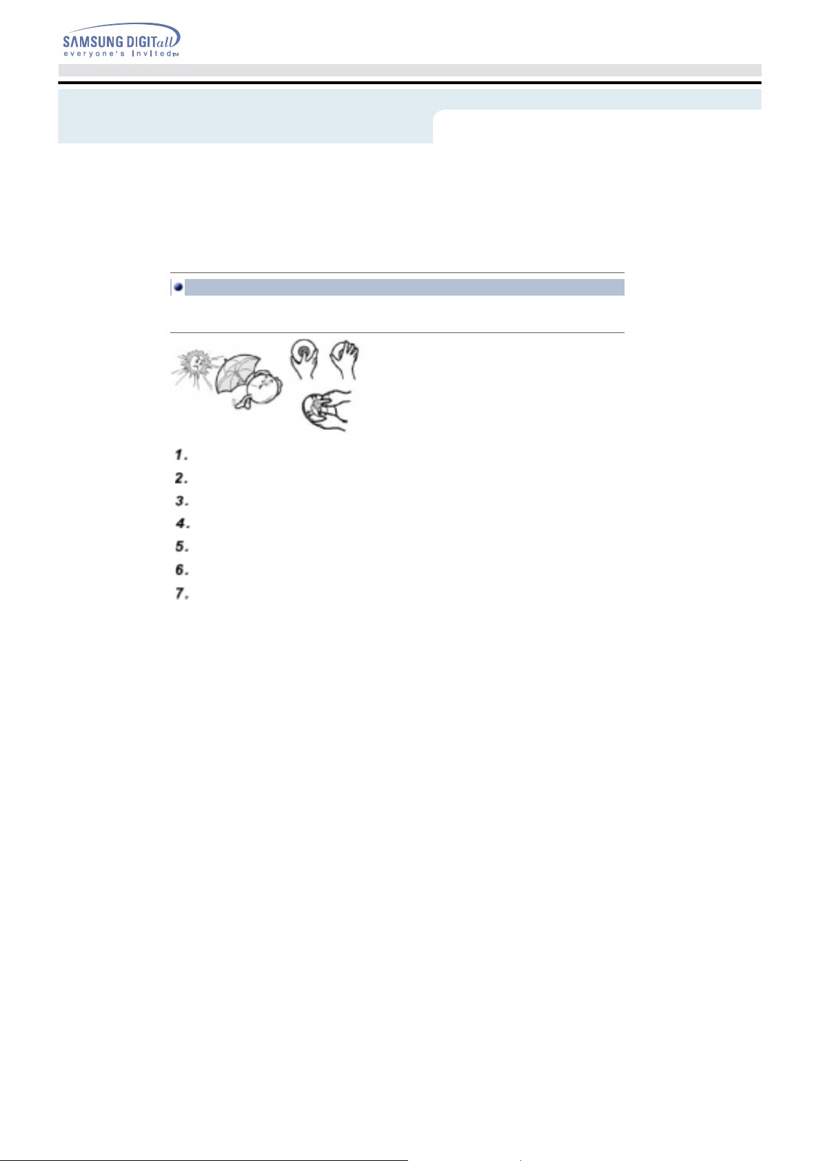
To ensure a long service life for your discs and drive, follow the pre-cautions below when storing and cleaning
your discs.
Do not place a disc in direct sunlight.
Store a disc vertically in a well-ventilated and stable location.
Do not write or attach a label on a di sc.
Do not drop a disc or place heavy objects on it.
Do not touch the surface of a disc; hold it by the edges.
To clean a disc, polish lightly from the inside of the disc to the outside with a soft cotton cloth.
Do not leave the disc compart ment open when you are not using it.
Page 17

p
Using the Drive
Connecting the Cables
Upgrading the Firmware Flash Memory
The product firmware can be upgraded by downloading the updated file from the following Web site:
http://samsung-ODD.com
://samsung.com
Htt
Page 18
Using the Drive
Connecting the Cables
System Requirements
Before you install the DVD-ROM drive, we strongly recommend that you check that your setup meets the
system requirements listed below.
Item Description
Computer Intel Pentium II (or higher), 128 MB of RAM (or higher) with an IDE interface
Disk space 100 MB minimum
Windows version Windows 98 / 2000 / ME / XP Windows (or higher)
The RPC feature is supported on DVD players and is used with DVD-video discs (such as movies). Currently,
the motionpicture industry has divided the worldinto different regions or zones thatcorrespond to the regional
markets intowhich the motion picture industry releasesmovies. Simply put, RPC codes are placedon movies
marketed throughout the world,based on the region of the world inwhich they are being sold. These
RPCcodes help control and prevent piratingof new movies into other motion pictureregions prior to their true
releasedates within those markets.
The DVD-ROM drive supports RPCphase II. In the RPC-2 mode, the localcode can be changed by users.
RPC-2is selected by default for the DVD-ROM drive.
You can change the region code up t ofive times via an MPEG application.
Please contact your dealer or local SAMSUNG representative if you wish tochange the local code more than
fivetimes.
DVD Region Protection Coding (RPC):
Page 19

Troubleshootin
Connecting the Cables
Problem Meaning / Solution
The DVD-ROM drive is not
detected by the computer.
After installing the DVD-ROM
drive, the PC gets slower.
The DVD-ROM drive is not
recognized by MS-DOS.
The DVD-ROM drive is not
detected by Windows.
No sound is heard from an
audio CD.
A CD is not read or is read
too slowly.
The disc compartment will
not open.
When the MPEG software
plays a Video CD, the pictures
are not regular and the running
speed is too slow.
The Disc is not in message is
displayed even though a disc
has been inserted.
The DVD-ROM drive is not
detected after it is connected to
a sound card.
Check that the power, audio and IDE cables are correctly connected
to the computer.
Change the IDE cable and reconnect it to the computer.
Preferably, connect a second IDE cable to the DVD-ROM drive in
master mode.
Check the position of the jumper in the master/slave select terminal.
Reinstall the device driver or update it with the latest version by
downloading it from the Samsung Web site.
-
Http://samsung-ODD.com
-
Http://samsung.com
This case may occur when there is a Windows installation problem;
reinstall Windows.
Check whether the audio ca ble is correctly connected to the sound
output terminal on the DVD-R OM drive and the sound card CD-IN
terminal.
Check that the sound card is operational.
Adjust the volume control of windows.
Check whether the CD is of good quality and clean it, if necessary.
Check that the power cabl e is correctly connected.
Power off and disconnect the PC.
Insert a pin or unfolded p a per clip in the emergency hole and push
firmly until the disc compartment opens.
Adjust the size of the replay screen.
After checking the display resolution, adjust it, if necessary.
The computer may not recognize the disc if you start playback too
quickly after inserting the disc. Open and close the disc
compartment and try again.
Clean the disc and try again.
The interface mode of the sound card is AT-BUS.
You must therefore connect the DVD-ROM drive to the IDE port on
the PC mother board, rather than to the sound card, or instal l an IDE
compatible sound card.
Page 20
Specifications
SAMSUNG
instructions are thus subject to change without notice.
continually strives to improve its products. Both the design specifications and these user
Technical Specifications
ITEM
Model Name
ITEM
Disc
Disc types supported in
read mode
Disc diameter
DRIVE PERFORMANCE
Data transfer rate
Sustained : Max. 21,600KB/sec(16X) | Max. 7,200KB/sec (48X)
PIO mode 4 : 16.6MB/sec
Multiword DMA mode 2 : 16.6MB/sec
UDMA mode 2 : 33MB/sec
ACCESS TIME (typical)
Data Buffer capacity
Laser
Slide mechanism
Spindle motor
Load mechanism
ERROR RATE
ERROR RATE
FRONT PANEL
Eject button
Indicator(LED)
REAR PANEL
Required power
Interface connector
Audio output
Jumper block
OPERATING ENVIRONMENT
Operations
Storage
GENERAL
Dimensions
Net weight
RELIABILITY
MTBF
SH-D162C(TS-H352C)
DVD | CD
CD-DA(Audio), CD-ROM, CD-R, CD-RW, Photo-CD(Single,
Multi-session), Video CD ready, Enhanced CD, CD-I/FMV,
CD-TEXT,CD-Plus, DVD-ROM, DVD-VIDEO, DVD+R, DVD-R,
DVD+RW, DVD-RW, DVD-RAM
120mm or 80mm
100ms
512KB
Semiconductor laser
Stepping motor, Sensorless
Brushless motor
Tray. DC motor (Soft Eject). Horizontal/Vertical.
10
Auto eject or Auto inject
BUSY
1.5A (rms)
ATAPI
Line out 0.7V ± 20%(rms) : 47Kohm
Molex 70203 or other compatible models
Temperature: 5~45°C Humidity: 10~80%
Temperature: -25~60°C Humidity: 10~90%
148.2 (W) x 42 (H) x 184 (D) mm (including bezel)
750 g
125,000 POH(Duty 20%)
-15
| Mode 1:10
-12
, Mode 2:10
-9
 Loading...