

SAMSUNG SH09ZP2 Service Manual
ROOM AIR CONDITIONER
INDOOR UNIT
SH07ZP2
SH07ZP2A
SH09ZP2
SH09ZP2A
SH12ZP4
SH12ZP4A
AQ07P2GE
AQ09P2GE
AQ12P4GE
AQT12P4GB
AQT12P4GE
SERVICE
OUTDOOR UNIT
SH07ZP2X
SH07ZP2AX
SH09ZP2X
SH09ZP2AX
SH12ZP4X
SH12ZP4AX
UQ07P2GE
UQ09P2GE
UQ12P4GE
UQT12P4GB
UQT12P4GE
Manual
CONTENTSAIR CONDITIONER
1. Product Specifications
2. Operating Instructions
3. Disassembly and Reassembly
4. Refrigerating Cycle Diagram
5. Set Up the Model Option
6. Troubleshooting
7. Exploded Views and Parts List
8. Block Diagram
9. PCB Diagram
10. Wiring Diagram
11. Schematic Diagram

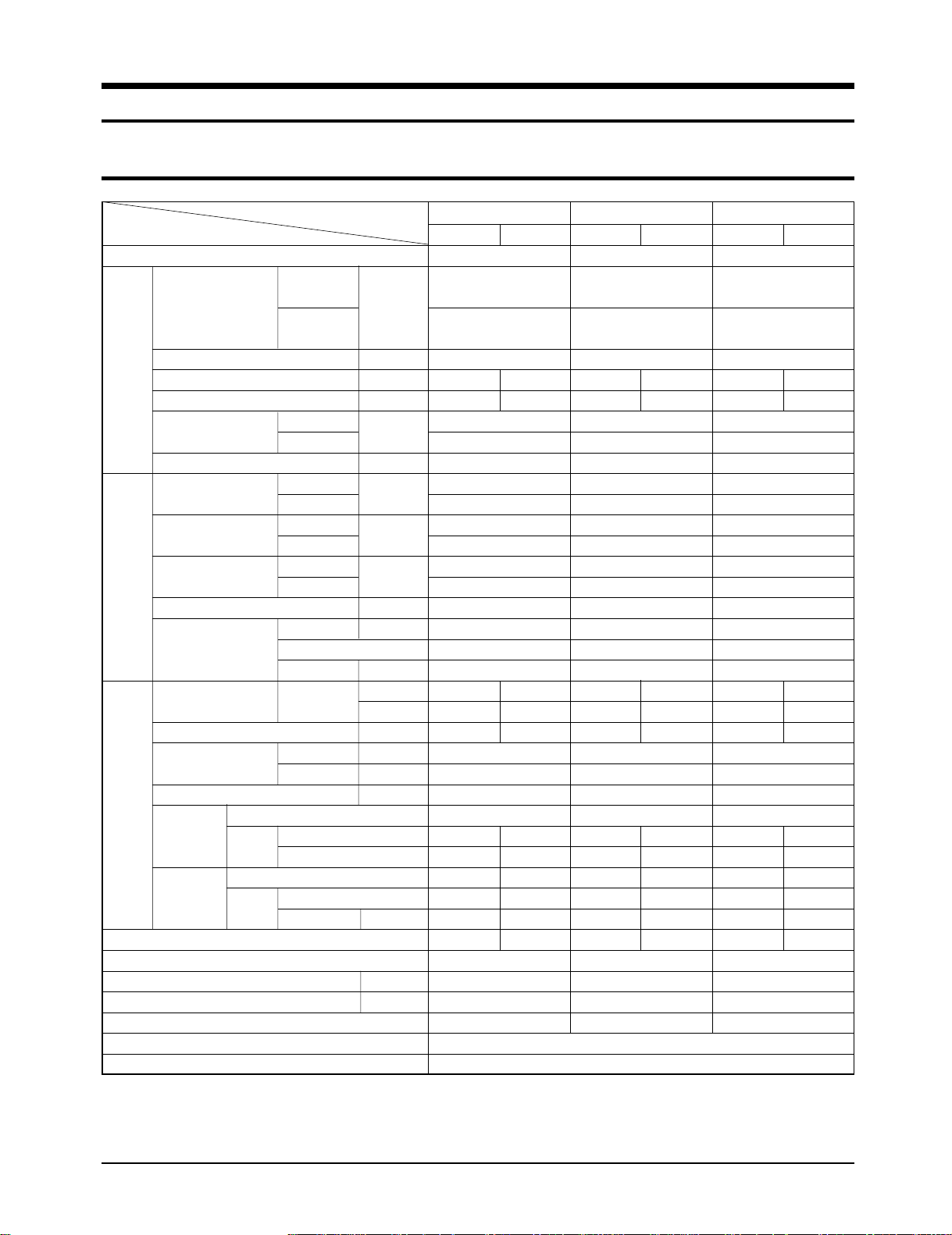
1. Product Specifications
1-1 Table
Item
Type
Capacity
( ) : RUSSIA, CIS
Performance
Dehumidifying
Air Volume m
Noise dB
Energy Efficiency Ratio
Power V-Hz
Power Consumption
Operating Current
Power Factor
Power
Starting Current A
Power Cord Number of Core Wire
Outer Dimension
Weight kg
Refrigerant Pipe
Drain Hose D x L(mm)
Size
Compressor Motor Type
Blower Motor Type
Heat Exchanger
Refrigerant Control Unit
Freezer Oil Capacity cc
Refrigerant to Change(R22) g
Protection Device(OLP)
Cooling Test Condition
Maximum Operation Condition
Type
Type
Cooling
Heating
Cooling
Heating
Cooling
Heating
Cooling
Heating
Cooling
Heating
Length m
Capacity A
W x H x D
Liquid mm x L(m)
GAS mm x L(m)
Rated Output
Rated Output W
Model
-
|/h
3
/min
W/W
W
A
%
mm
inch
SH07ZP2 SH09ZP2 SH12ZP4
Indoor unit Outdoor unit Indoor unit Outdoor unit Indoor unit Outdoor unit
Wall-mounted
2.20kW
(7,500 BTU/h)
2.30kW
(7,800 BTU/h)
0.9
6.5 24
36 50
3.24
3.65
1-220 / 240-50
680
630
3.0
2.8
98.6
97.8
21.0
-
-
250V-10 / 16A
795x258x179 660x495x235
31.3x10.2x7.0 26.0x19.5x9.3
7.5 22.5
ø6.35 x 5
ø9.52 x 5
ø18 x 2,000
Rotary
--
--
Cross-flow Propeller
steel steel
11 25
2ROW 10STEP 1ROW 18STEP
CAPILLARY TUBE
290
680
MRA99137-9201
INDOOR UNIT : DB27˚C WB19˚C OUTDOOR UNIT : DB35˚C WB24˚C
INDOOR UNIT : DB32˚C WB23˚C OUTDOOR UNIT : DB43˚C WB26˚C
Wall-mounted
2.60kW
(8,990 BTU/h)
2.90kW
(8,990 BTU/h)
1.4
7.0 24
40 51
2.89
3.41
1-220 / 240-50
900
850
4.0
3.8
97.8
97.3
21.0
-
-
250V-10 / 16A
795x258x179 660x495x235
31.3x10.2x7.0 26.0x19.5x9.3
7.5 26.5
ø6.35 x 5
ø9.52 x 5
ø18 x 2,000
Rotary
--
--
Cross-flow Propeller
steel steel
11 25
2ROW 10STEP 1ROW 18STEP
CAPILLARY TUBE
350
680
MRA98776
890x285x179 720x530x260
35.0x11.2x7.0 28.3x20.9x10.2
2ROW 12STEP 1ROW 20STEP
Wall-mounted
3.50kW
(11,990 BTU/h)
3.80kW
(11,990 BTU/h)
1.9
8.2 24
43 53
3.04
3.45
1-220 / 240-50
1,150
1,100
5.1
5.0
98.0
96.5
32.0
-
-
250V-10 / 16A
8.5 33.0
ø6.35 x 5
ø12.7 x 5
ø18 x 2,000
Rotary
--
--
Cross-flow Propeller
steel steel
15 25
CAPILLARY TUBE
410
800
Internal
1Samsung Electronics
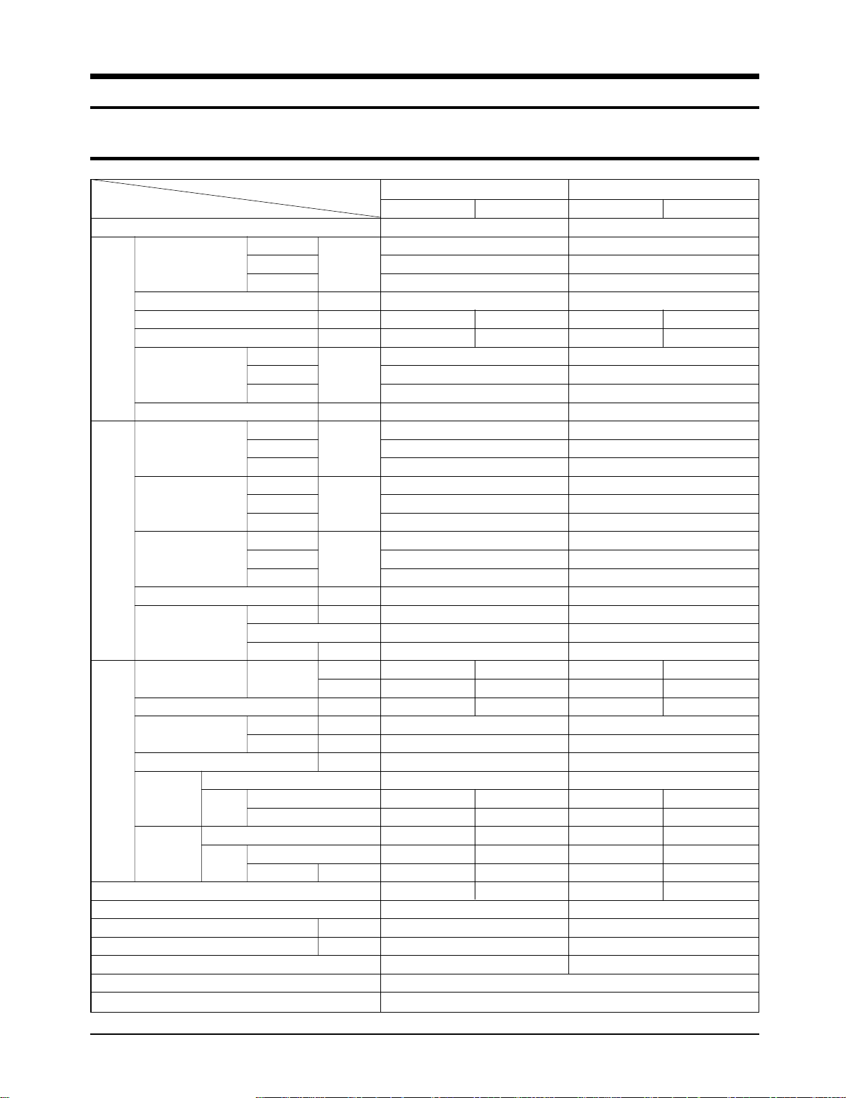
Table(cont.)
Item
Type
Capacity
( ) : RUSSIA, CIS
Perfor-
mance
Dehumidifying |/h
Air Volume m3/min
Noise dB
Energy Efficiency Ratio
Power V-Hz
Power Consumption
Operating Current
Power Factor
Power
Starting Current A
Power Cord Number of Core Wire
Outer Dimension
Weight kg
Refrigerant Pipe
Drain Hose D x L(mm)
Size
Compressor Motor Type
Blower Motor Type
Heat Exchanger
Refrigerant Control Unit
Freezer Oil Capacity cc
Refrigerant to Change(R22) g
Protection Device(OLP)
Cooling Test Condition
Maximum Operation Condition
Type
Type
Cooling
Heating
Cooling
Heating
Cooling
Heating
Cooling
Heating
Cooling
Heating
Length m
Capacity A
W x H x D
Liquid mm x L(m)
GAS mm x L(m)
Rated Output
Rated Output W
Model
-
W/W
W
A
%
mm
inch
SH07ZP2A SH09ZP2A SH12ZP4A
Indoor unit Outdoor unit Indoor unit Outdoor unit Indoor unit Outdoor unit
Wall-mounted
2.30kW
(7,500BTU/h)
2.40kW
(7,800BTU/h)
0.9
6.5 24
36 50
3.15
3.53
1-220/240-50
730
680
3.3
3.1
96.2
95.4
21.0
-
-
250V-10/16A
795x258x179 660x495x235
31.3x10.2x7.0 26.0 x 19.5x9.3
7.5 26.0
ø6.35 x 5
ø9.52 x 5
ø18 x 2,000
Rotary
--
--
Cross-Flow Propeller
steel steel
15 25
2ROW 10STEP 1ROW 18STEP
CAPILLARY TUBE
360
630
RAC12144-9622
INDOOR UNIT : DB27˚C WB19˚C OUTDOOR UNIT : DB35˚C WB24˚C
INDOOR UNIT : DB32˚C WB23˚C OUTDOOR UNIT : DB43˚C WB26˚C
Wall-mounted
2.65kW
(8,990BTU/h)
2.90kW
(8,990BTU/h)
1.4
7.0 24
39 51
2.82
3.30
1-220/240-50
940
880
4.3
4.0
95.0
95.7
21.0
-
-
250V-10/16A
795x258x179 660x 495x235
31.3x10.2x7.0 26.0x19.5x9.3
7.5 26.5
ø6.35 x 5
ø9.52 x 5
ø18 x 2,000
Rotary
--
--
Cross-Flow Propeller
steel steel
15 25
2ROW 10STEP 1ROW 18STEP
CAPILLARY TUBE
360
600
RAC12110-9622
890x285x179 720x530x260
35.0x11.2x7.0
Cross-Flow Propeller
2ROW 12STEP 1ROW 20STEP
Wall-mounted
3.50kW
(11,990BTU/h)
3.80kW
(11,990BTU/h)
1.9
8.2 24
43 53
3.04
3.45
1-220/240-50
1,150
1,100
5.1
5.0
98.0
95.7
32.0
-
-
250V-10/16A
28.3x20.9x10.2
8.5 33.0
ø6.35 x 5
ø12.7 x 5
ø18 x 2,000
Rotary
--
--
steel steel
15 25
CAPILLARY TUBE
600
800
RAC12074-9622
Samsung Electronics2

Item
Type
Capacity
Dehumidifying |/h
Air Volume m3/min
Perfor-
mance
Power
Noise dB
Energy Efficiency Ratio
Power V-Hz
Power Consumption
Operating Current
Power Factor
Starting Current A
Power Cord Number of Core Wire
Outer Dimension
Weight kg
Refrigerant Pipe
Drain Hose D x L(mm)
Type
Compressor Motor Type
Size
Type
Blower Motor Type
Heat Exchanger
Refrigerant Control Unit
Freezer Oil Capacity cc
Refrigerant to Change(R22) g
Protection Device(OLP)
Cooling Test Condition
Maximum Operation Condition
Cooling
Heating
Cooling
Heating
Cooling
Heating
Cooling
Heating
Cooling
Heating
Length m
Capacity A
W x H x D
Liquid mm x L(m)
GAS mm x L(m)
Rated Output
Rated Output W
BTU/W.h
Model
BTU/h
W
A
%
mm
inch
AQ07P2GE AQ09P2GE AQ12P4GE
Indoor unit Outdoor unit Indoor unit Outdoor unit Indoor unit Outdoor unit
Wall-mounted
7,500
7,800
0.9
6.5 24
36 50
10.3
11.5
1-220/240-50
730
680
3.3
3.1
96.2
95.4
21.0
-
-
250V-10/16A
795x258x179 660x495x235
31.3x10.2x7.0 26.0 x 19.5x9.3
7.5 26.0
ø6.35 x 5
ø9.52 x 5
ø18 x 2,000
Rotary
--
--
Cross-Flow Propeller
steel steel
15 25
2ROW 10STEP 1ROW 18STEP
CAPILLARY TUBE
360
630
RAC12144-9622
INDOOR UNIT : DB27˚C WB19˚C OUTDOOR UNIT : DB35˚C WB24˚C
INDOOR UNIT : DB32˚C WB23˚C OUTDOOR UNIT : DB43˚C WB26˚C
Wall-mounted
9,000
10,000
1.4
7.0 24
39 51
9.57
11.4
1-220/240-50
940
880
4.3
4.0
95.0
95.7
21.0
-
-
250V-10/16A
795x258x179 660x 495x235
31.3x10.2x7.0 26.0x19.5x9.3
7.5 26.5
ø6.35 x 5
ø9.52 x 5
ø18 x 2,000
Rotary
--
--
Cross-Flow Propeller
steel steel
15 25
2ROW 10STEP 1ROW 18STEP
CAPILLARY TUBE
360
600
RAC12110-9622
Wall-mounted
12,000
13,000
1.9
8.2 24
43 53
10.4
11.8
1-220/240-50
1,150
1,100
5.1
5.0
98.0
95.7
32.0
-
-
250V-10/16A
890x285x179 720x530x260
35.0x11.2x7.0
8.5 33.0
Cross-Flow Propeller
steel steel
2ROW 12STEP 1ROW 20STEP
CAPILLARY TUBE
28.3x20.9x10.2
ø6.35 x 5
ø12.7 x 5
ø18 x 2,000
Rotary
--
--
15 25
600
800
RAC12074-9622
3Samsung Electronics
Table(cont.)
Item
Type
Cooling
Capacity Heating BTU/h
SASO
Dehumidifying |/h
Perfor-
mance
Air Volume m
Noise dB
Cooling
Energy Efficiency Ratio Heating BTU/W.h
SASO
Power V-Hz
Cooling
Power Consumption Heating W
SASO
Cooling
Operating Current Heating A
Power
Power Factor Heating %
Starting Current A
Power Cord Number of Core Wire
Outer Dimension
Weight kg
Refrigerant Pipe
Size
Drain Hose D x L(mm)
Type
Compressor Motor Type
Type
Blower Motor Type
Heat Exchanger
Refrigerant Control Unit
Freezer Oil Capacity cc
Refrigerant to Change(R22) g
Protection Device(OLP)
Cooling Test Condition
Maximum Operation Condition
SASO
Cooling
SASO
Length m
Capacity A
W x H x D
Liquid mm x L(m)
GAS mm x L(m)
Rated Output
Rated Output W
Model
3
/min
mm
inch
AQT12P4GB AQT12P4GE
Indoor unit Outdoor unit Indoor unit Outdoor unit
Wall-mounted
12,000
13,000
10,500
1.9
8.2 2.4
43 53
10.0
10.5
7.44
1-220-60
1,200
1,240
1,410
5.5
5.7
6.5
99.2
98.9
98.6
32.0
-
-
250V-10/16A
890x285x179 720x530x260
35.0x11.2x7.0 28.3x20.9x10.2
8.5 33.0
ø6.35 x 5
ø12.7 x 5
ø18 x 2,000
Rotary
--
--
Cross-Flow Propeller
steel steel
15 25
2ROW 12STEP 2ROW 24STEP
CAPILLARY TUBE
600
960
RBC12107-12500
INDOOR UNIT : DB27˚C WB19˚C OUTDOOR UNIT : DB35˚C WB24˚C
INDOOR UNIT : DB32˚C WB23˚C OUTDOOR UNIT : DB43˚C WB26˚C
890x285x179 720x530x260
35.0x11.2x7.0 28.3x20.9x10.2
Cross-Flow Propeller
2ROW 12STEP 2ROW 24STEP
Wall-mounted
12,000
13,000
-
1.9
8.2 2.4
43 53
10.0
11.0
-
1-220/240-50
1,200
1,180
-
5.3
5.2
-
98.4
98.7
-
32.0
-
-
250V-10/16A
8.5 33.0
ø6.35 x 5
ø12.7 x 5
ø18 x 2,000
Rotary
--
--
steel steel
15 25
CAPILLARY TUBE
410
940
RBC12050-12500
Samsung Electronics4
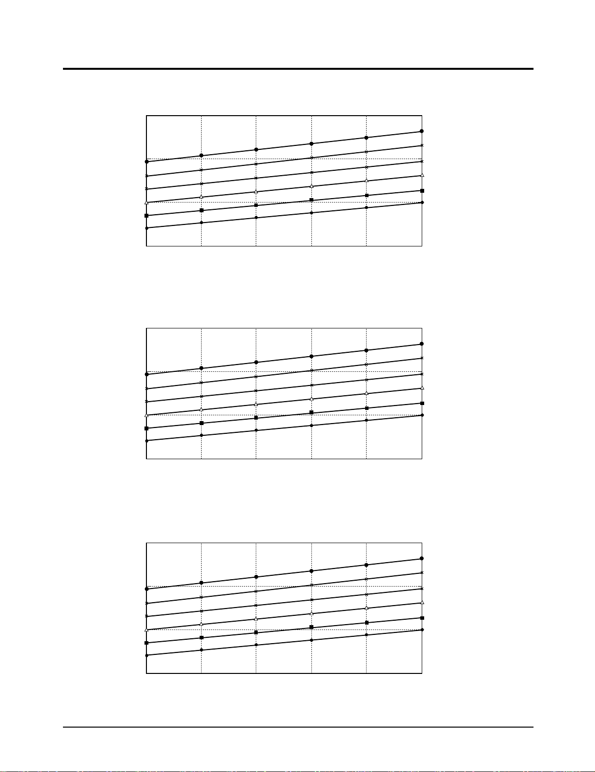
1-2 Pressure Graph
■ 7K BTU
7
G)
2
■ 9K BTU
2
6
5
Low pressure (kg/cm
4
20 25 30 35 40 45
6.5
G)
5.5
4.5
32.4/24.0
30.6/22.5
28.8/21.0
27.0/19.0
24.0/17.0
21.5/15.0
Indoor inlet air D.B. temp (˚C)
Outdoor inlet air D.B. temp (˚C)
32.4/24.0
30.6/22.5
28.8/21.0
27.0/19.0
24.0/17.0
21.5/15.0
■ 12K BTU
Low pressure (kg/cm
3.5
20 25 30 35 40 45
6.5
G)
2
5.5
4.5
Low pressure (kg/cm
3.5
20 25 30 35 40 45
Indoor inlet air D.B. temp (˚C)
Outdoor inlet air D.B. temp (˚C)
32.4/24.0
30.6/22.5
28.8/21.0
27.0/19.0
24.0/17.0
21.5/15.0
Indoor inlet air D.B. temp (˚C)
Outdoor inlet air D.B. temp (˚C)
5Samsung Electronics
2. Operating Instructions
Low Medium High
Automatic(rotated : )
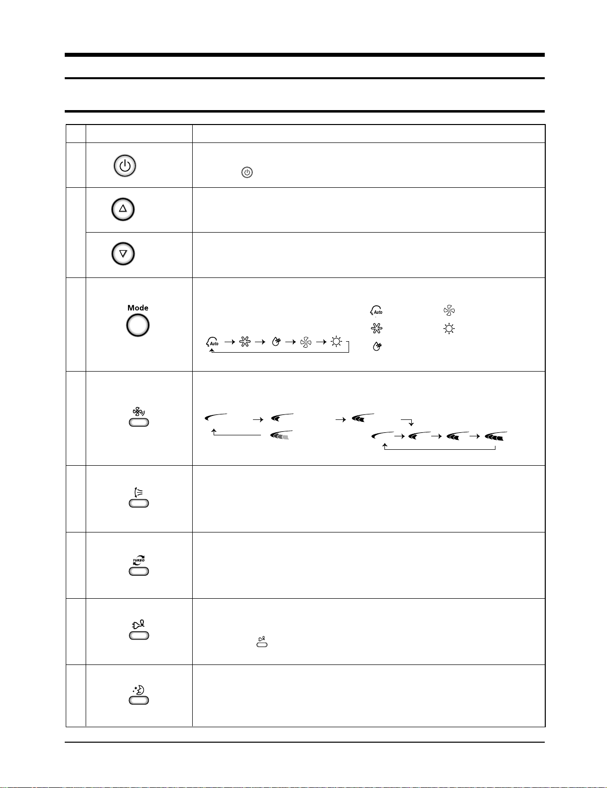
2-1 The Feature of Key in remote control
NAMED OF KEYNo
1
2
3
4
(On/Off)
(UP)
(DOWN)
On/Off button.
Press the button to stop or run the air conditioner.
Temperature adjustment button(UP).
To increase the temperature by the pressing the temperature button.
Temperature adjustment button(DOWN).
To decrease the temperature by the pressing the temperature button.
Mode selection button.
Each time you press this button
Mode is changed in the following order
Fan speed adjustment button.
Each time you press this button, FAN SPEED is changed in the following order.
FUNCTION OF KEY
: Auto Mode : Fan Only
: Cool Mode : Heat Mode
: Dry Mode
5
6
7
8
Swing button.
It adjusts the airflow to upward and downward.
Turbo button.
The air conditioner cools or heats the room as quickly as possible.
After 30minutes, the air conditioner is reset automatically to the previous mode.
Energy saving button.
If you wish to save energy when using your air conditioner, select the Energy saving
mode with the button.
Sleep button.
The sleep timer can be used when you are cooling or heating your room to switch the
air conditioner off automatically after a period of 6 hours.
Samsung Electronics6
Operating Instructions
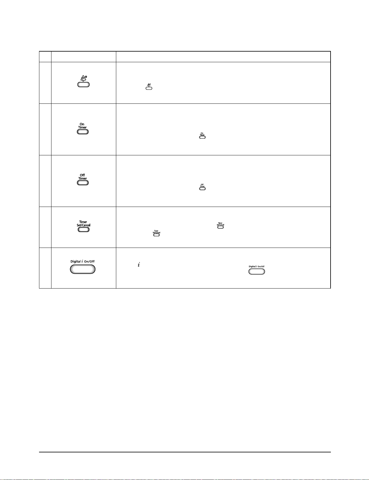
10
11
12
NAMED OF KEYNo
9
Anion button.
Press the button to generate ion from the air conditioner.
On Timer button.
The On Timer enables you to switch on the air conditioner automatically after
a given period of time that is from 30 minutes to 24 hours.
To set the operating time, press the button one or more times until the required
time display.
Off Timer button.
The Off Timer enables you to switch off the air conditioner automatically after
a given period of time that is from 30 minutes to 24 hours.
To set the operating time, press the button one or more times until the required
time display.
Timer Set/Cancel button.
After setting On Timer or Off Timer, press the button to set it completely.
And press the button again to cancel On Timer or Off Timer set.
FUNCTION OF KEY
13
Digital On/Off button.
If you want to turn off the display during operation press the button.
7Samsung Electronics
Operating Instructions
2-1-1 Name & Function of Key in remote control
1. AUTO MODE : In this mode, operation mode(COOL,
HEAT) is selected automatically by the room temperature
of initial operation.
Room Temp
Tr≥ 21°C+∆T
21°C +∆T>Tr
Cool Operation (Set Temp:24˚C+∆T)
Heat Operation (Set Temp:22˚C+∆T)
Operation Type
∆T= -1°C, -2°C, 0°C, +1°C, +2°C
∆T is controlled by setting temperature up/down key of
remote control
2. COOL MODE : The unit operates according to the
difference between the setting and room temperature.
(18°C~30°C)
3. HEAT MODE : The unit operates according to the
difference between the setting and room temperature.
(16°C~30°C)
*Prevention against cold wind : In order to prevent the
cool air from flowing out at the heat mode, the indoor fan
does not operate or operates very slowly in the
following cases. At this time, the indoor heat exchanger
will be preheating.
- For 3~5 minutes after the initial operation
- For deicing operation
- The operation of an indoor fan in accordance with
the temperature of an indoor heat exchanger
The temperature of
indoor heat exchanger
below 28˚C
28˚C~below 34˚C
34˚C~below 40˚C
above 40˚C
Indoor fan speed
off
LL Speed
L Speed
Setting Speed
*High temperature release function : It is a function to
detect an outdoor overload by the sensor of an indoor
heat exchanger and to turn the outdoor fan or the
compressor ON/OFF for safety.
*Deice : Deicing operation is controlled by indoor unit's
heat exchanger temperature and accumulating time of
compressor's operation.
Deice ends by sensing of the processing time by deice
condition.
4. DRY MODE : Has 3 states, each determined by room
temperature.
The unit operates in DRY mode.
*Compressor ON/OFF Time is controlled compulsorily
(can not set up the fan speed, always breeze).
*Protective function : Low temperature release.
(Prevention against freeze)
5. TURBO MODE : This mode is available in AUTO, COOL,
HEAT, DRY, FAN MODE.
When this button is pressed at first, the air conditioner is
operated “powerful” state for 30 minutes regardless of the
set temperature, room temperature.
When this button is pressed again, or when the operating
time is 30 minutes, turbo operation mode is canceled and
returned to the previous mode.
*But, if you press the TURBO button in DRY or FAN
mode that is changed with AUTO mode automatically.
6. SLEEP MODE : Sleep mode is available only in COOL or
HEAT mode.
The operation will stop after 6 hours.
*In COOL mode : The setting temperature is automatical-
ly raised by 1°C each 1hour When the temperature
has been raised by total of 2°C, that temperature is
maintained.
*In HEAT mode : The setting temperature is automatically
dropped by 1°C each 1hour.
When the temperature has been dropped by total of 2°C,
that temperature is maintained.
7. FAN SPEED : Manual (3 step), Auto (4 step)
Fan speed automatically varies depending on both the
difference between setting and the room temperature.
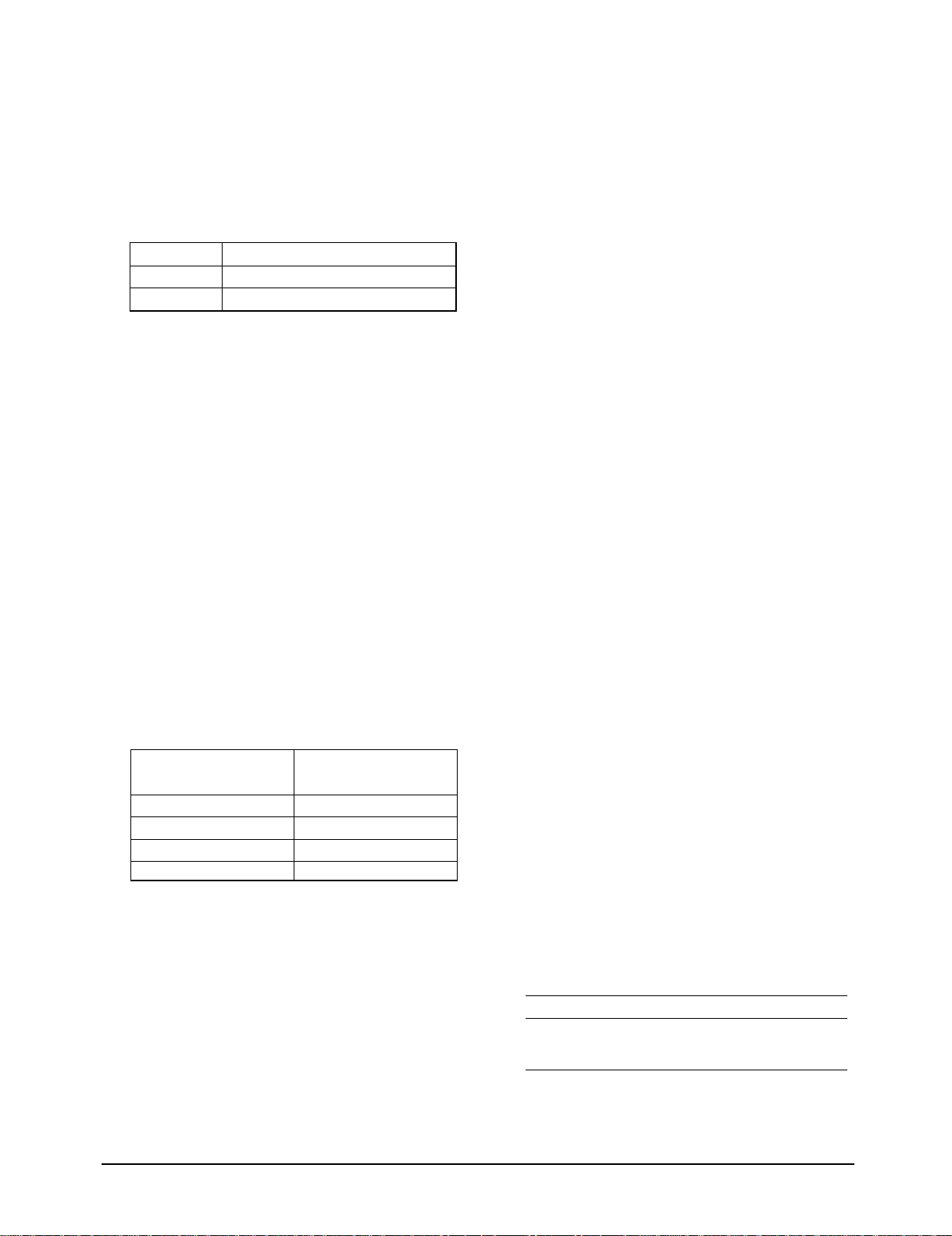
8. COMPULSORY OPERATION :
For operating the air conditioner without the remote
control.
*The air conditioner starts up in the most suitable mode
for the room temperature:
Room Temperature
Less than 21˚C
21˚C or above
Operating Mode
Heat
Cool
Temperature Setting
22˚C approx.
24˚C approx.
Samsung Electronics8
Operating Instructions
9. SWING : BLADE-H is rotated vertically by the stepping
motor.
*Swing Set : Press the button under the remote
control is displayed on LCD the and the blades
move up and down. If the one more time press the
button, blades location is stop.
10. SETTING THE ON/OFF TIMER. :
*ON TIMER : The On Timer enables you to switch on the
air conditioner automatically after a given period of time.
You can set the period of time from 30 minutes to 24
hours.
*OFF TIMER : The Off Timer enables you to switch off
the air conditioner automatically after a given period of
time. You can set the period of time from 30 minutes to
24 hours.
1 1. GENERATING ANION :
The air conditioner can generate anion with an ionizer in
the indoor unit.
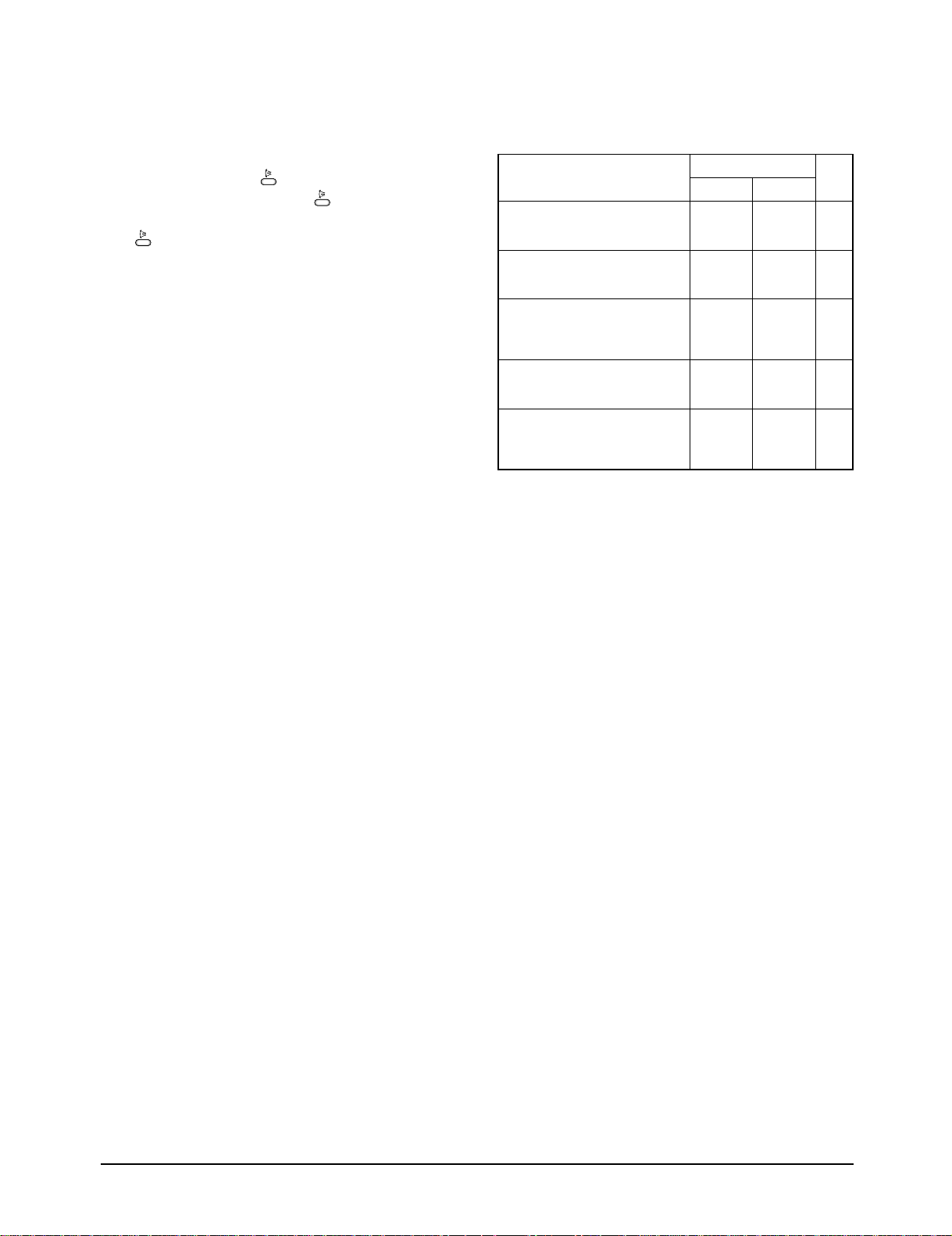
12. SELF DIAGNOSIS
Error Mode
Indoor unit room temperature sensor
error (open or short)
Indoor unit heat exchanger
temperature sensor error(open or short)
Indoor FAN MOTOR error :
Keep the RPM value 450 below for
15 seconds
EEPROM error
Error in option
In case of No option set-up
In case of option data error
DISPLAY 7-SEGMENT
Operation Off Operation On
OFF E1
OFF E2
OFF E3
OFF E6
All lamp
blinking
All lamp
blinking
Remark
13. BUZZER SOUND : Whenever the On/Off button is
pressed or whenever change occurs to the condition
which is set up or select, the compulsory operation mode,
buzzer is sounded "beep".
9Samsung Electronics
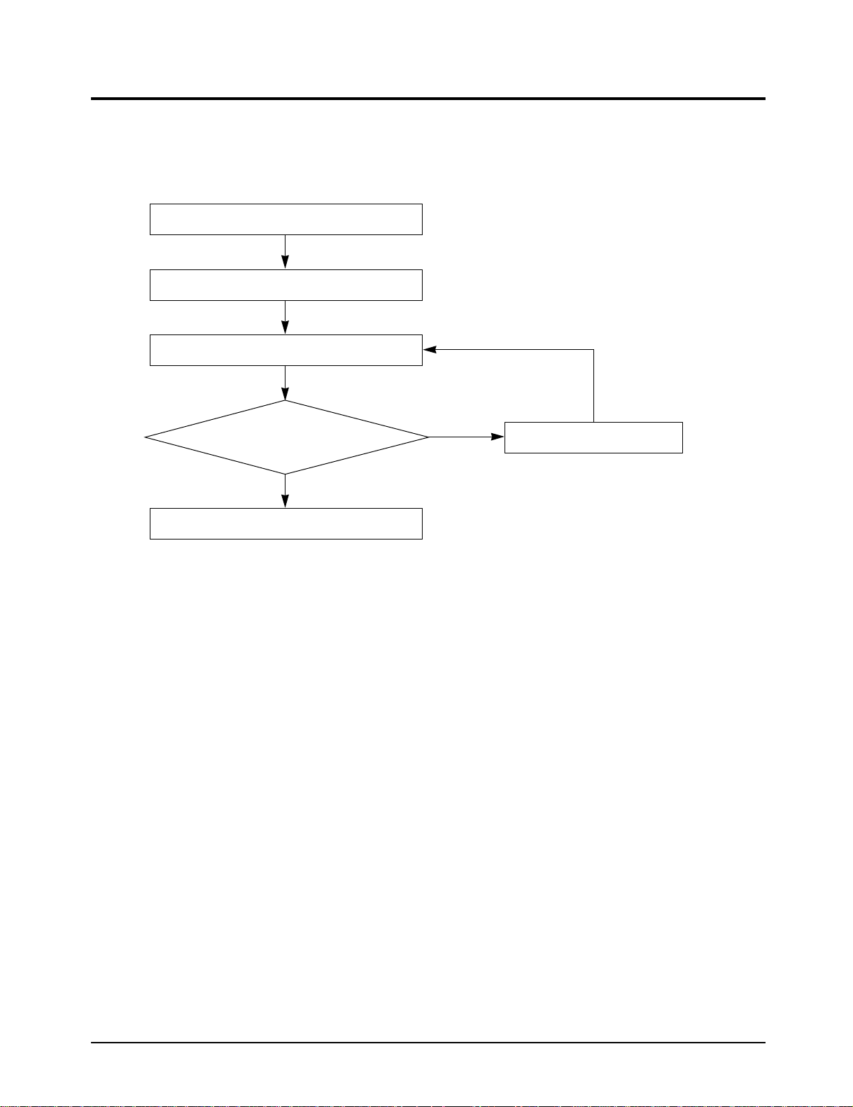
2-2 Replace PCB Model option
2-2-1 Replace PCB model option
Remove power cord
Replace the PCB module
Check the connection and plug in
Does all display lamp blink?
Yes
Refer to set up the Model option(17~19page)
No
Replace another PCB
Samsung Electronics10
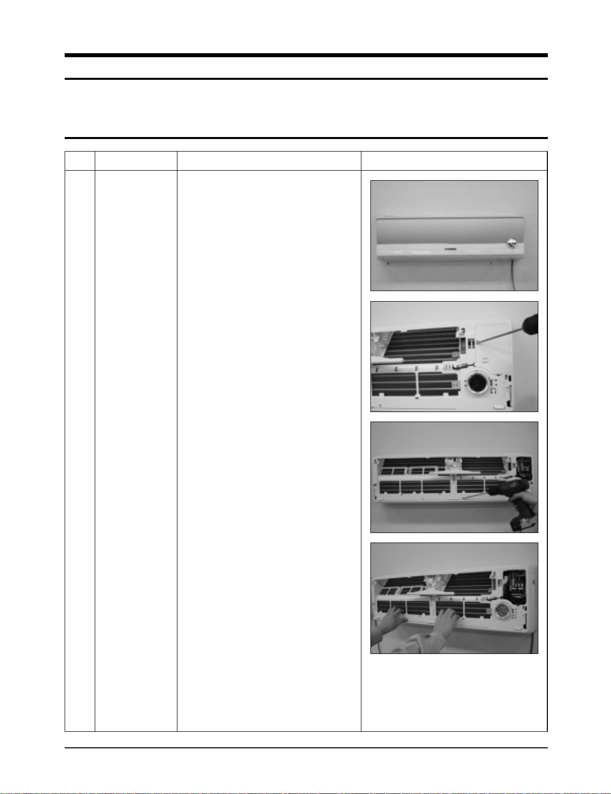
3. Disassembly and Reassembly
Stop operation of the air conditioner and remove the power cord before repairing the unit.
3-1 Indoor Unit
No Parts Procedure Remark
1 Front Panel
1) Stop the air conditioner operation and block
the main power.
2) Separate tape of Front Panel upper.
3) Slide the lower Front Grille down, then
disassemble it by pulling it forwards.
4) Open the upper Front Grille by pulling right
and left sides of the Grille.
5) Take the left and right Filter out.
6) Loosen one of the right screw and detach
the Terminal Cover.
7) Detach the thermistor from the Front Grille.
8) Loosen 5 fixing screws of Front Grille.
9) Pull the lower left and right of discharge
softly for the outside cover to be pulled out.
11Samsung Electronics
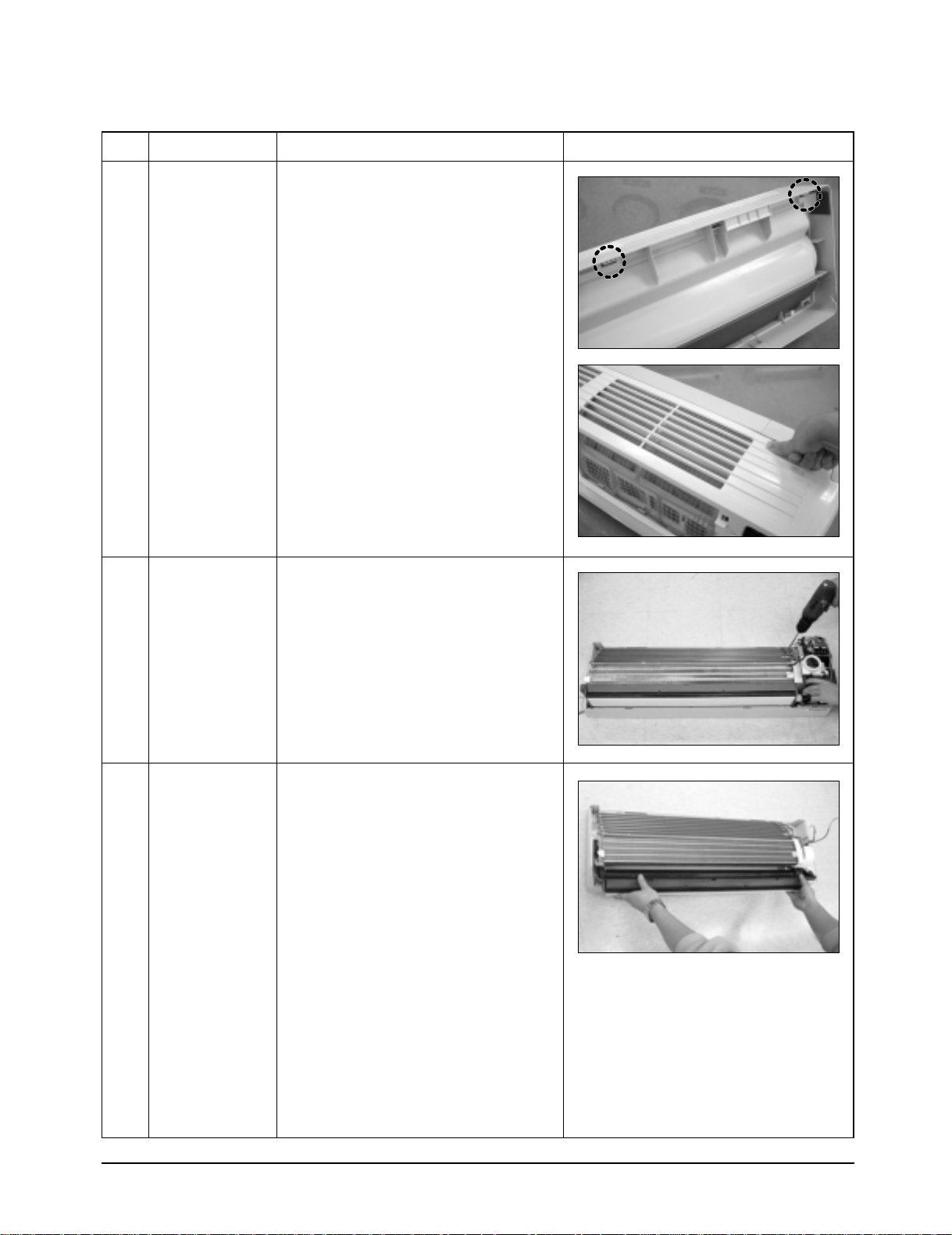
Disassembly and Reassembly
No Parts Procedure Remark
10) At first, press the left and center hook of
the back side of the Panel Grille with the
thumb to remove the hook. And press the
right of the upper side of the Panel Grille
with the fingers. And then disassemble the
Panel Grille.
2
3
Electrical Parts
(Main PCB)
Tray Drain
1) Take all the connector of PCB upper side
out.(Including Power Cord)
2) Detach the outdoor unit connection wire
from the Terminal Block.
3) If pulling the main PCB up, it will be taken
out.
1) Pull Tray Drain out from the Back Body.
Samsung Electronics12
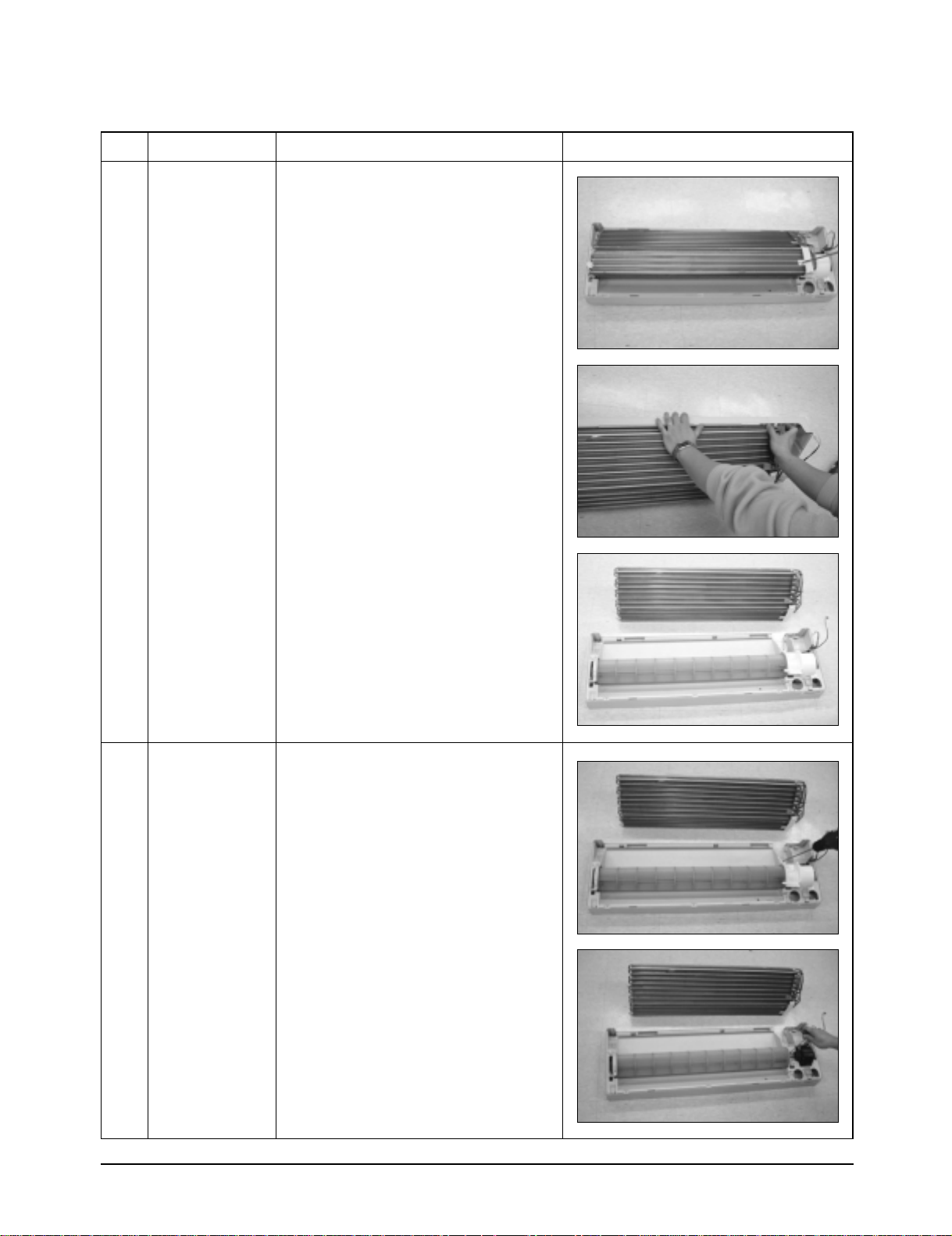
Disassembly and Reassembly
No Parts Procedure Remark
4
Heat Exchanger
1) Loosen 2 fixing earth screws of right side.
2) Detach the Connection Pipe.
3) Detach the Holder Pipe at the rear side.
4) Loosen 3 fixing screws of right and left
side.
5) Detach the Heat Exchanger from the
indoor unit.
5
Fan Motor
&
Cross Fan
1) Loosen 2 fixing screws and separate the
Motor Holder.
2) Loosen 1 fixing screw of Fan Motor.
(with a M3 wrench)
3) Detach the Fan Motor from the Fan.
4) Detach the Fan from the left Holder
Bearing.
13Samsung Electronics
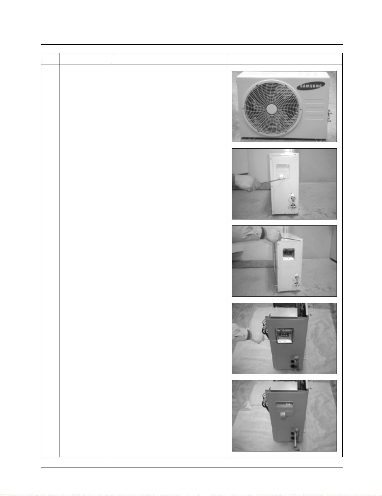
3-2 Outdoor Unit
No Parts Procedure Remark
1 Common Work
1) Loosen 1 fixing screw and detach the
Cover Terminal.
2) Loosen 1 fixing screw and detach the
Cover Control.
3) Detach the connection wire from the
Terminal Block.
4) Loosen 13 fixing screws and detach the
Cabinet-Front.
5) Loosen 1 fixing screw of Ass'y E-part.
6) Loosen 4 fixing screws and detach the
Cabinet-Side.
Samsung Electronics14
Disassembly and Reassembly
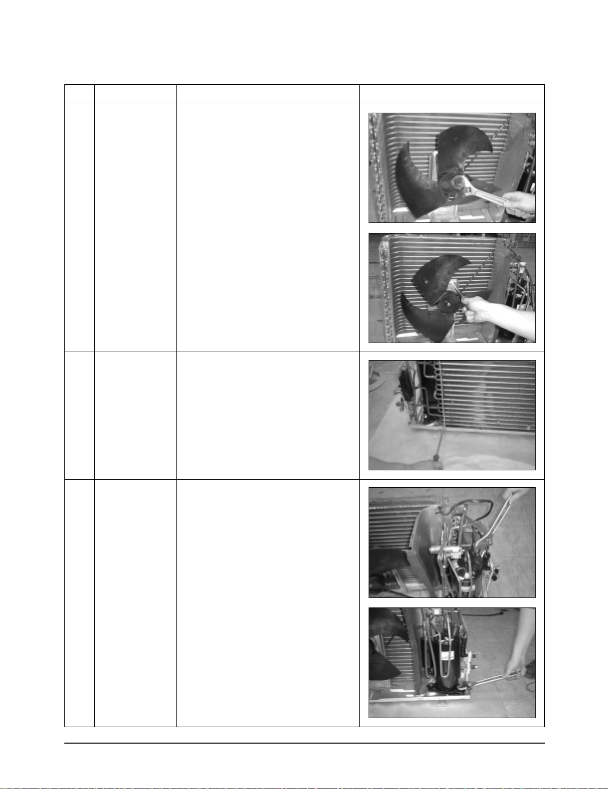
No Parts Procedure Remark
2
3
Fan
&
Motor
Heat Exchanger
1) Detach the Nut Flange (Turn to the clock-
wise).
2) Detach the Fan.
3) Loosen 4 fixing screws to detach the
Motor.
4) Loosen 5 fixing screws and detach the
Motor Bracket from the Base.
1) Loosen 2 fixing screws of left and right
side.
2) Disassemble the inlet and outlet pipe by
welding.
3) Detach the Heat Exchanger.
4
Compressor
1) Open the Terminal Cover of Compressor
and unscrew the Connection Terminal.
2) Disassemble the inlet and outlet pipe of
Compressor by welding.
3) Loosen 3 bolts of the lower part.
4) Detach the Compressor.
15Samsung Electronics
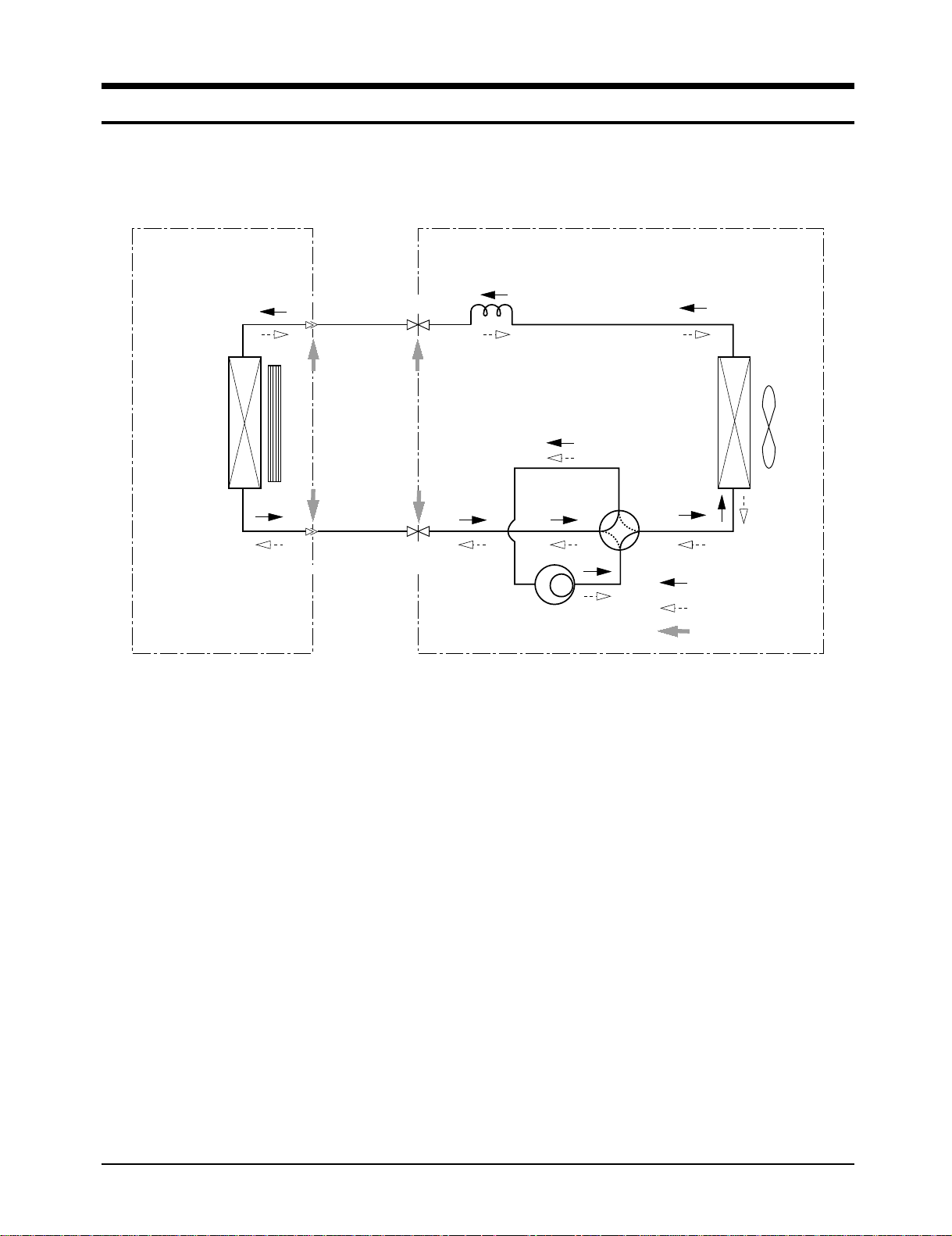
4. Refrigerating Cycle Diagram
Indoor Unit
Heat
Exchanger
(Evaporator)
Outdoor Unit
Capillary tube
T
1
Liquid side
Cross fan
T
2
Gas side
2-Way valve
3-Way valve
Compressor
Heat
Exchanger
(Condenser)
Propeller fan
4-Way valve
Cooling
Heating
Gas leak check point
Samsung Electronics16
 Loading...