

Samsung ASH091VE, ASH121VE, ASH074VE, ASH094VE, ASH124VE Installation Manual
...
INSTALLATION MANUAL
MANUAL DE INSTALACIÓN
MANUALE D’INSTALLAZIONE
MANUAL DE INSTALAÇÃO
MANUEL D’INSTALLATION
INSTALLATIONS-HANDBUCH
Split-type Room Air Conditioner (Cool and Heat)
Aire acondicionado doméstico sistema Split (Refrigeración y Calefacción)
Condizionatore d’aria per ambienti ad unità Separate (Raffreddamento e Riscaldamento)
Aparelho de ar condicionado tipo Split (Refrigeração e Aquecimento)
Climatiseur de type Séparé (Refroidissement et Chauffage)
Geteilte raumklimaanlage (Kühlen und Wärmen)
ENGLISH
ESPAÑOL
ITALIANO
PORTUGUÉS
FRANÇAIS
DEUTSCH
ESIPFD
DB68-00217A(8)
ASH070VE/D
ASH090VE/D
ASH120VE/D
ASH071VE/D
ASH091VE/D
ASH121VE/D
ASH074VE/D
ASH094VE/D
ASH124VE/D
ASH075VE/D
ASH095VE/D
ASH125VE/D
Indoor Unit
Outdoor Unit
AXH070VE/D
AXH090VE/D
AXH120VE/D
AXH071VE/D
AXH091VE/D
AXH121VE/D
AXH074VE/D
AXH094VE/D
AXH124VE/D
AXH075VE/D
AXH095VE/D
AXH125VE/D
AQ07A1(A2)VE
AQ09A1(A2)VE/B
AQ12A1(A2)VE/B
SH07YA0
SH09YA0
SH12YA0
SH07YAA(B)
SH09YAA(B)
SH12YAA(B)
SH09ZV
SH12ZV
Indoor Unit
Outdoor Unit
UQ07A1(A2)VE
UQ09A1(A2)VE/B
UQ12A1(A2)VE/B
SH07YA0X
SH09YA0X
SH12YA0X
SH07YAA(B)X
SH09YAA(B)X
SH12YAA(B)X
XSH09ZV
XSH12ZV

E-2

E-3
Contents
◆ PREPARING THE INSTALLATION
■ Deciding on Where to Install the Air Conditioner.......................................... 4
■ Air Conditioner and Accessories................................................................... 6
◆
INSTALLING THE INDOOR UNIT
■ Fixing the Installation Plate........................................................................... 7
■ Purging the Unit............................................................................................. 8
■ Connecting the Assembly Cable................................................................... 8
■ Installing and Connecting the Indoor Unit Drain Hose .................................. 9
■ Installing and Connecting the Indoor Unit Assembly Piping......................... 10
■ Cutting/Extending the Piping ........................................................................ 11
◆ INSTALLING THE OUTDOOR UNIT
■ Connecting the Cables to the Outdoor Unit.................................................. 12
■ Checking Correct Earthing............................................................................ 13
■ Installing and Connecting the Outdoor Unit Drain Hose............................... 14
■ Fixing the Unit in Position ............................................................................ 14
◆
COMPLETING THE INSTALLATION
■ Connecting Up and Purging the Circuit......................................................... 15
■ Performing Leak Tests................................................................................... 16
■ Placing the Indoor Unit in Position................................................................ 16
■ Checking and Testing Operations ................................................................. 17
■ Installing the Remote Control Holder............................................................ 18
■ Explaining Operations to the Owner ............................................................. 18
◆
TECHNICAL SPECIFICATIONS
ENGLISH

Deciding on Where to Install the Air Conditioner
E-4
When deciding on the location of the air conditioner with the owner, the following restrictions
must be taken into account.
General
Do NOT install the air conditioner in a location where it will come into contact with the following elements:
◆ Combustible gases
◆ Saline air
◆ Machine oil
◆ Sulphide gas
◆ Special environmental conditions
If you must install the unit in such conditions, first consult your dealer.
Indoor Unit
◆ There must be no obstacles near the air inlet and outlet.
◆ Install the indoor unit on a surface that can support its weight.
◆ Choose a position that enables the piping and cables to be easily connected to the outdoor unit and the
recommended length of 5 metres to be respected.
◆ Leave enough clearance beneath the indoor unit to enable the filters to be removed without hindrance.
◆ Maintain sufficient clearance around the indoor unit, as indicated in the diagram on the page opposite.
◆ Make sure that the water dripping from the drain hose runs away correctly and safely.
Outdoor Unit
◆ The outdoor unit must NEVER be placed on its side or upside down, as the compressor lubrication oil will run into the
cooling circuit and seriously damage the unit.
◆ Choose a location that is dry and sunny, but not exposed to direct sunlight or strong winds.
◆ Do not block any passageways or thoroughfares.
◆ Choose a location where the noise of the air conditioner when running and the discharged air do not disturb any
neighbours.
◆ Choose a position that enables the piping and cables to be easily connected to the indoor unit and the recommended
length of 5 metres to be respected.
◆ Install the outdoor unit on a flat, stable surface that can support its weight and does not generate any unnecessary
noise and vibration.
◆ Position the outdoor unit so that the air flow is directed towards the outside, as indicated by the arrows on the top of
the unit.
◆ Maintain sufficient clearance around the outdoor unit, as indicated in the diagram on the page opposite.
◆ If the outdoor unit is installed at a height, ensure that its base is firmly fixed in position; the maximum height(“H”:
indicated in the diagram on the page opposite.) is 7 metres.
◆ Make sure that the water dripping from the drain hose runs away correctly and safely.
◆ You have just purchased a split-type room air conditioner and it has
been installed by your installation specialist.
◆ This device must be installed according to the national electrical rules.
CCCCAAAAUUUUTTTTIIIIOOOONN
NN
PREPARING THE INSTALLATION
Deciding on Where to Install the Air Conditioner(cont.)
E-5
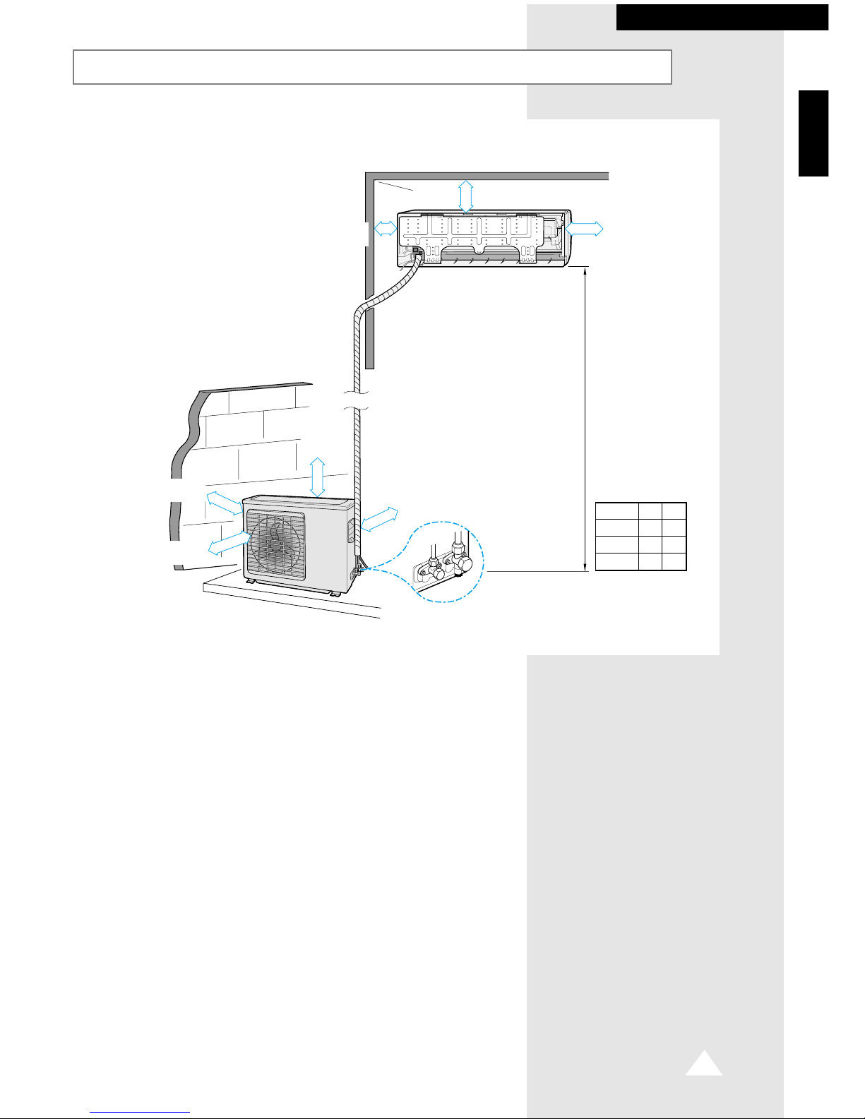
125 mm
or more
30 mm or more
Respect the clearances and maximum lengths indicated in the diagram below when installing the unit.
125 mm
or more
600 mm
minimum
300 mm
minimum
300 mm
minimum
600 mm
minimum
“L” metres
maximum
“H”metres maximum
ENGLISH
PREPARING THE INSTALLATION
Model
✴✴07✴✴
✴✴09✴✴
✴✴12✴✴
Model
✴✴07✴✴
✴✴09✴✴
✴✴12✴✴
H
7
7
7
L
10
10
15
Air Conditioner and Accessories
E-6
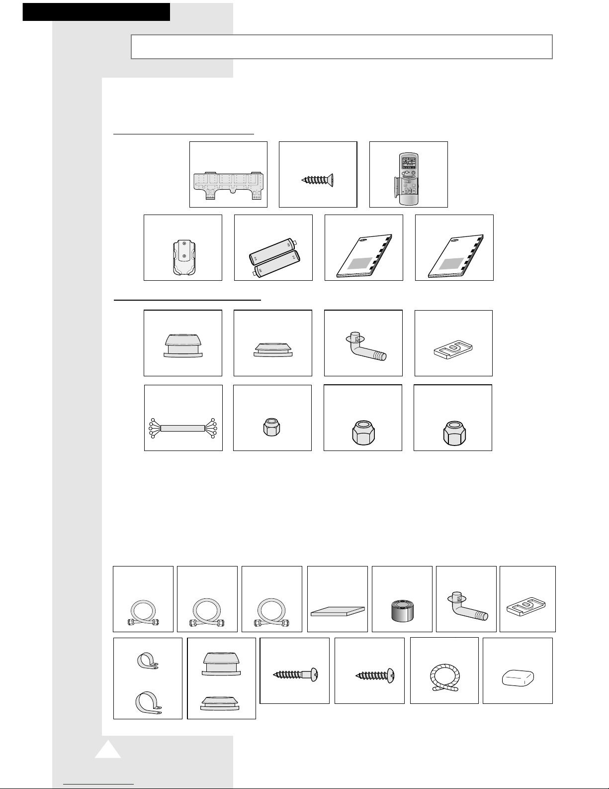
The following accessories are supplied with the air conditioner.
➢ The quantities are indicated in parentheses.
Accessories in the Indoor Unit Case
M
O
D
E
T
U
R
B
O
O
F
F
O
W
N
E
R
’
S
I
N
S
T
R
U
C
T
I
O
N
S
M
A
N
U
A
L
D
E
I
N
S
T
R
U
C
C
I
O
N
E
S
I
S
T
R
U
Z
I
O
N
I
P
E
R
L
’
U
S
O
M
A
N
U
A
L
D
E
I
N
S
T
R
U
˝
E
S
M
A
N
U
E
L
D
’
U
T
I
L
I
S
A
T
I
O
N
G
E
B
R
A
U
C
H
S
A
N
W
E
I
S
U
N
G
S
p
l
u
t
-
t
y
p
e
R
o
o
m
A
i
r
C
o
n
d
i
t
i
o
n
e
r
A
i
r
e
a
c
o
n
d
i
c
i
o
n
a
d
o
d
o
m
s
t
i
c
o
s
i
s
t
e
m
a
S
p
l
i
t
C
o
n
d
i
z
i
o
n
a
t
o
r
e
d
’
a
r
i
a
p
e
r
a
m
b
i
e
n
t
i
a
d
u
n
i
t
S
e
p
a
r
a
t
e
A
p
a
r
e
l
h
o
d
e
a
r
c
o
n
d
i
c
i
o
n
a
d
o
t
i
p
o
S
p
l
i
t
C
l
i
m
a
t
i
s
e
u
r
d
e
t
y
p
e
s
p
a
r
G
e
t
e
i
l
t
e
r
a
u
m
k
l
i
m
a
a
n
l
a
g
e
I
N
S
T
A
L
L
A
T
I
O
N
M
A
N
U
A
L
M
A
N
U
A
L
D
E
I
N
S
T
A
L
A
C
I
O
N
M
A
N
U
A
L
E
D
’
I
N
S
T
A
L
L
A
Z
I
O
N
E
M
A
N
U
A
L
D
E
I
N
S
T
A
L
A
O
M
A
N
U
E
L
D
’
I
N
S
T
A
L
L
A
T
I
O
N
I
N
S
T
A
L
L
A
T
I
O
N
S
-
H
A
N
D
B
U
C
H
S
p
l
u
t
-
t
y
p
e
R
o
o
m
A
i
r
C
o
n
d
i
t
i
o
n
e
r
A
i
r
e
a
c
o
n
d
i
c
i
o
n
a
d
o
d
o
m
s
t
i
c
o
s
i
s
t
e
m
a
S
p
l
i
t
C
o
n
d
i
z
i
o
n
a
t
o
r
e
d
’
a
r
i
a
p
e
r
a
m
b
i
e
n
t
i
a
d
u
n
i
t
S
e
p
a
r
a
t
e
A
p
a
r
e
l
h
o
d
e
a
r
c
o
n
d
i
c
i
o
n
a
d
o
t
i
p
o
S
p
l
i
t
C
l
i
m
a
t
i
s
e
u
r
d
e
t
y
p
e
s
p
a
r
G
e
t
e
i
l
t
e
r
a
u
m
k
l
i
m
a
a
n
l
a
g
e
Accessories in the Outdoor Unit Case
➢ The five-wire assembly cable is depending on the option. [If they are not supplied, Using
the standard cable.(above 1.0mm
2
/area or approved according to IEC standard.)]
➢ The flare nuts, drain plug, drain cap A/B and rubber leg are only included when the air
conditioner is supplied without the assembly piping illustrated below.
The following connection accessories may be supplied, depending on the option. If they are not
supplied, it is recommended that you collect them together before starting to install the air
conditioner.
➢ If these accessories are supplied, they are located in the accessory box.
Installation Plate (1) FH.M4 x 12 Tapped
Screws (2)
Remote Control (1)
Remote Control
Holder (1)
Five-wire Assembly
Cable (1)
Drain Cap A(1)
Drain Cap B (1) Drain Plug (1)
Flare Nuts, 6.35mm
outer pipe diameter (2)
Flare Nuts, 9.52mm
outer pipe diameter (2)
(✴✴07✴✴, ✴✴09✴✴)
Flare Nuts, 12.70mm
outer pipe diameter (2)
(✴✴12✴✴)
Batteries for
Remote Control (2)
Owner’s Instruction
Booklet (1)
Installation Manual (1)
PREPARING THE INSTALLATION
M3.8 x 20 Screws
for Wood (10)
Putty 100g (1)M4 x 16 Tapped
Screws (10)
Drain Hose,
length 2m (2)
Rubber LEG (4)
Assembly Piping,
Ø6.35mm by 5m
(1)
Assembly Piping,
Ø9.52mm by 5m (1)
(✴✴07✴✴, ✴✴09✴✴)
Assembly Piping,
Ø12.70mm by 5m (1)
(✴✴12✴✴)
PE T3 Foam Tube
Insulation (1)
Vinyl Tape,
Width 50mm (1)
Drain plug (1) Rubber LEG (4)
Pipe Clamps B (3)
Pipe Clamps A(3)
Drain Cap B (1)
Drain Cap A(1)
 Loading...