

Samsung SGH-X481 Service Manual
GSM TELEPHONE
SGH-X481
GSM TELEPHONE
CONTENTS
1. Specification
2. Flow Chart of Troubleshooting
3. Exploded View and Parts List
4. Electrical Parts List
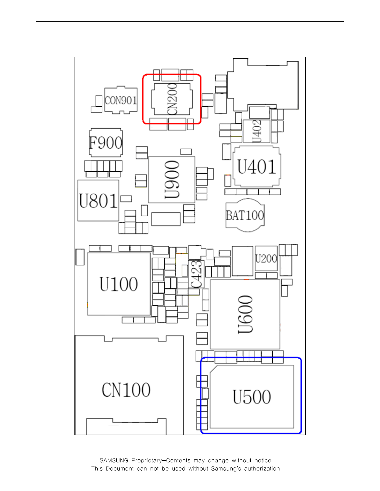
5. PCB Diagrams
6. Block Diagrams
7. Disassembly and
Assembly instructions
1. SGH-X481 Specification
1-1. GSM General Specification
GSM900
Phase 1
Freq. Band[MHz]
Uplink/Downlink
ARFCN range 1~124
Tx/Rx spacing 45MHz 45MHz 95MHz 80MHz
Mod. Bit rate/
Bit Period
Time Slot
Period/Frame
Period
Modulation 0.3GMSK 0.3GMSK 0.3GMSK 0.3GMSK
MS Power 33dBm~13dBm 33dBm~5dBm 30dBm~0dBm 30dBm~0dBm
890~915
935~960
270.833kbps
3.692us
576.9us
4.615ms
EGSM 900
Phase 2
880~915
925~960
0~124 &
975~1023
270.833kbps
3.692us
576.9us
4.615ms
DCS1800
Phase 1
1710~1785
1805~1880
512~885 512~810
270.833kbps
3.692us
576.9us
4.615ms
PCS1900
1850~1910
1930~1990
270.833kbps
3.692us
576.9us
4.615ms
Power Class 5 p cl ~ 1 5 p cl 5pcl ~ 19pcl 0pcl ~ 15pcl 0pcl ~ 15pcl
Sensitivity -102dBm -102dBm -100dBm -100dBm
TDMA Mux 8 8 8 8
Cell Radius 35Km 35Km 2Km -
1-1
SGH-X481 Speclflcation
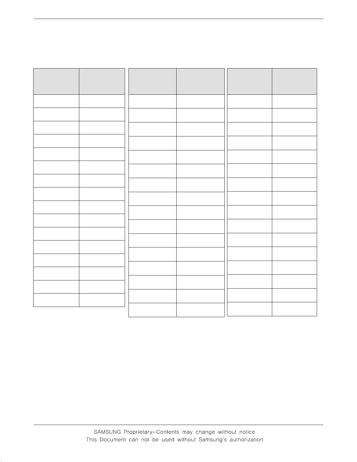
1-2. GSM Tx Power Class
TX Power
control level
5 33±2 dBm
6 31±2 dBm
7 29±2 dBm
8 27±2 dBm
9 25±2 dBm
10 23±2 dBm
11 21±2 dBm
12 19±2 dBm
13 17±2 dBm
14 15±2 dBm
15 13±2 dBm
16 11±3 dBm
17 9±3dBm
18 7±3 dBm
19 5±3 dBm
GSM900
TX Power
control level
0 30±3 dBm
1 28±3 dBm
2 26±3 dBm
3 24±3 dBm
4 22±3 dBm
5 20±3 dBm
6 18±3 dBm
7 16±3 dBm
8 14±3 dBm
9 12±4 dBm
10 10±4 dBm
11 8±4dBm
12 6±4 dBm
13 4±4 dBm
14 2±5 dBm
DCS1800
TX Power
control level
0 30±3 dBm
1 28±3 dBm
2 26±3 dBm
3 24±3 dBm
4 22±3 dBm
5 20±3 dBm
6 18±3 dBm
7 16±3 dBm
8 14±3 dBm
9 12±4 dBm
10 10±4 dBm
11 8±4dBm
12 6±4 dBm
13 4±4 dBm
14 2±5 dBm
PCS1900
15 0±5 dBm
1-2
15 0±5 dBm
2. SGH-X481
1. Baseband
2-
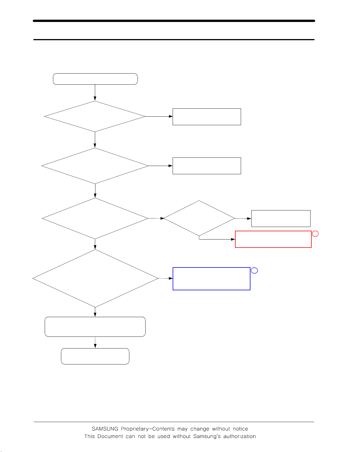
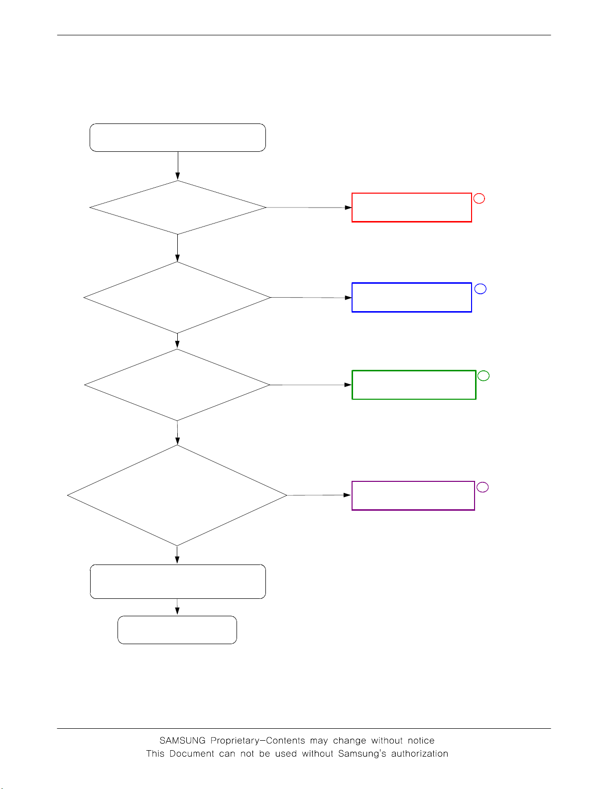
2-1-1. Power ON
'Power ON' does not work
Flow Chart of Troubleshooting
check the current
consumption
>= 100mA
Yes
Check the Voltage
of the Battery
>= 3.3V
Yes
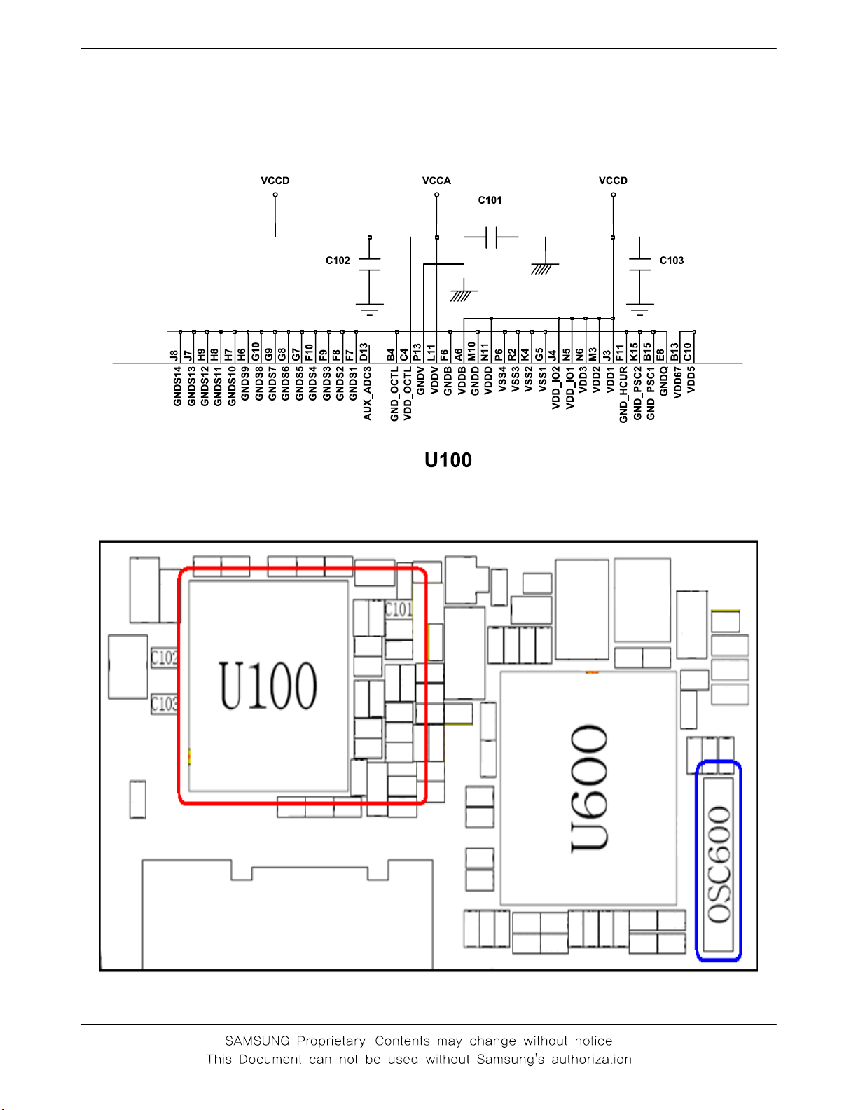
Check the pin C101,
C102,C103 of U100
is
>=2.8V
Yes
Check the clock
signal at pin #4 of
OSC600
No
No
No
No
Download again
Charge the battery
Check
"Power On"
key?
Check the clock generation
circuit OSC600
Yes
No
check keypad
1
check U100 and C101
2
Yes
Check the Initial Operation
Yes
END
2-1
SGH -X481 Flow Chart of Troubleshooting
2-2
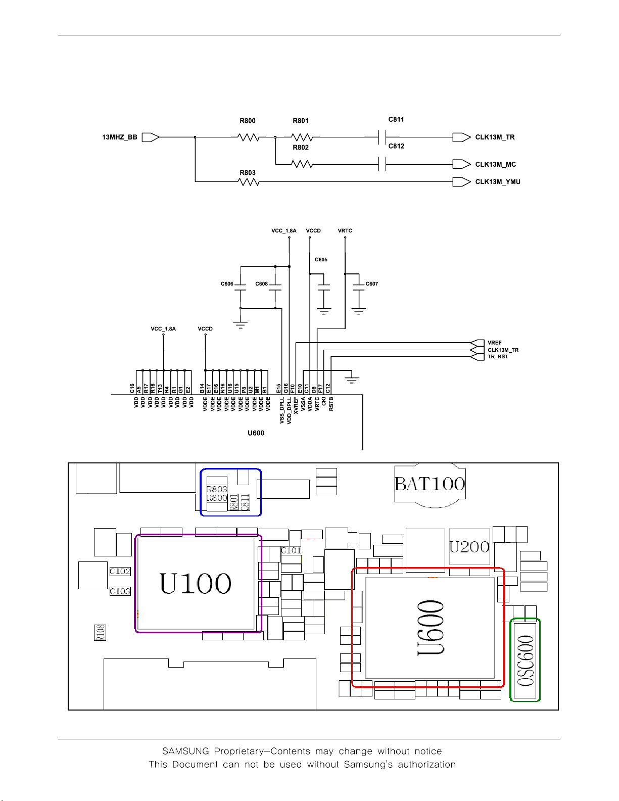
2-1-2. Initial
SGH-X481 Flow Chart of Troubleshooting
Initial Failure
check the pin
RSTB of U600 is
LOW?
Yes
check the pin CKI
of U600 is 13Mhz?
Yes
Check the clock
signal at pin #3 of
OSC600
Yes
Check the pin #9 of
U600 is HIGH and pin
#11, #13 is 2.9V?
No
No
No
No
Check U600
Check
R800,R801,C811,R803
check OSC600
Check U100
1
2
3
4
Yes
Check the Initial Operation
Yes
END
2-3
SGH -X481 Flow Chart of Troubleshooting
2-4
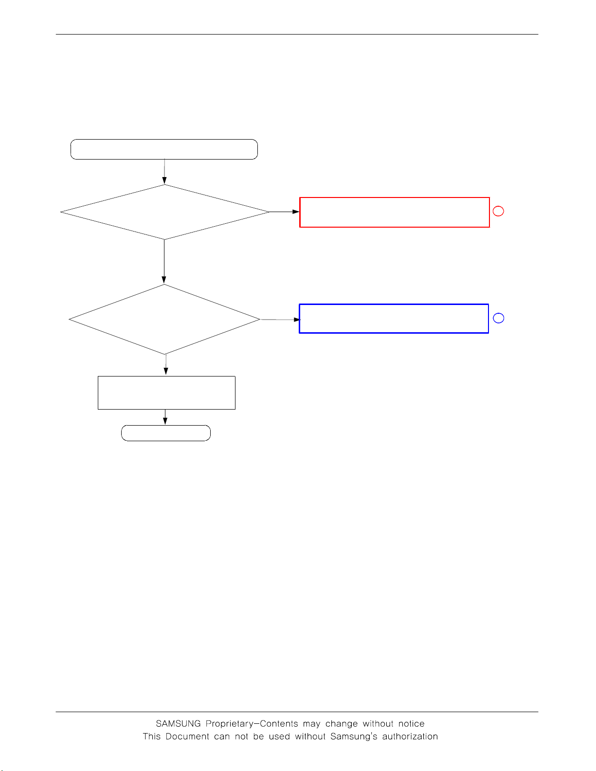
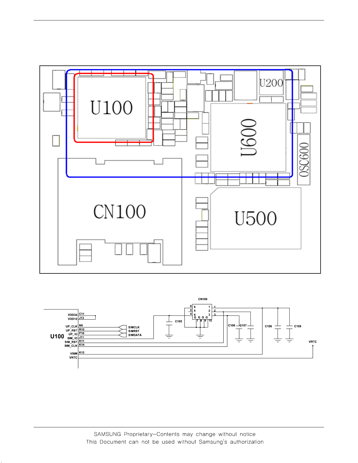
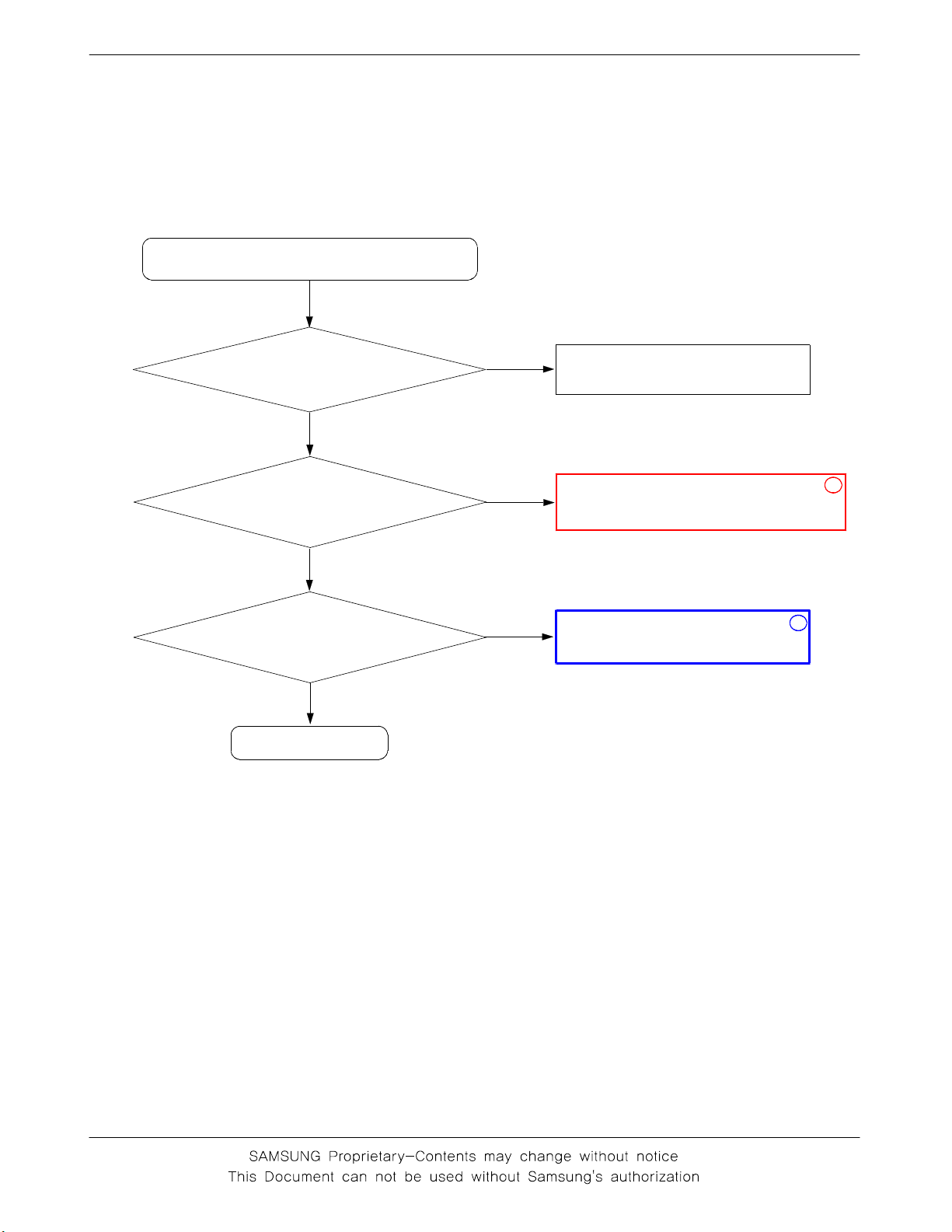
2-1-3. Sim Part
"Insert SIM" is displayed on the LCD
SGH-X481 Flow Chart of Troubleshooting
The voltage is 2.8V
at the pin#1 of CN100
Yes
Is there any signal
pin #2,3,4 of CN100?
Yes
Check the SIM Card
END
No
No
Check the U100
Check the U100 & U600
1
2
2-5
SGH -X481 Flow Chart of Troubleshooting
2-6
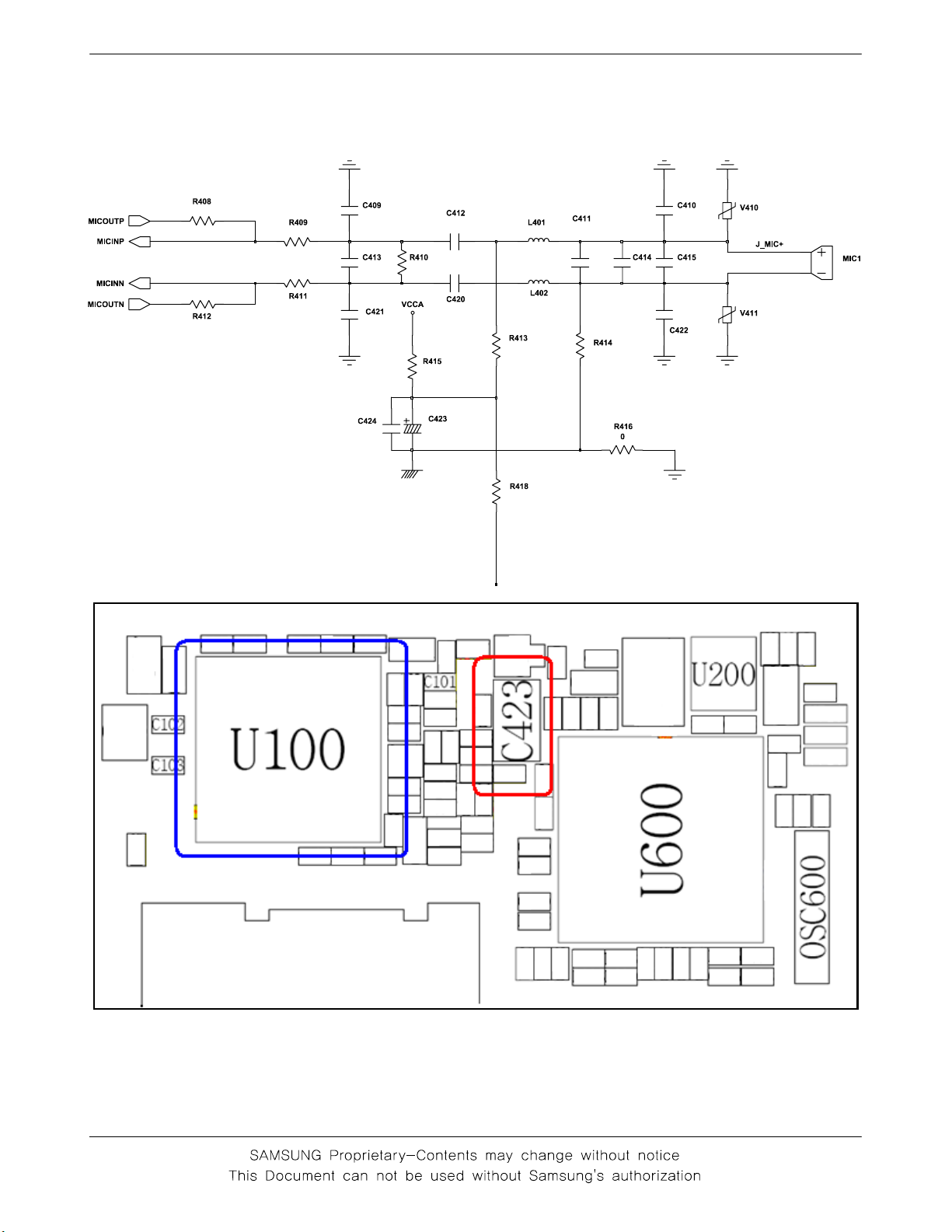
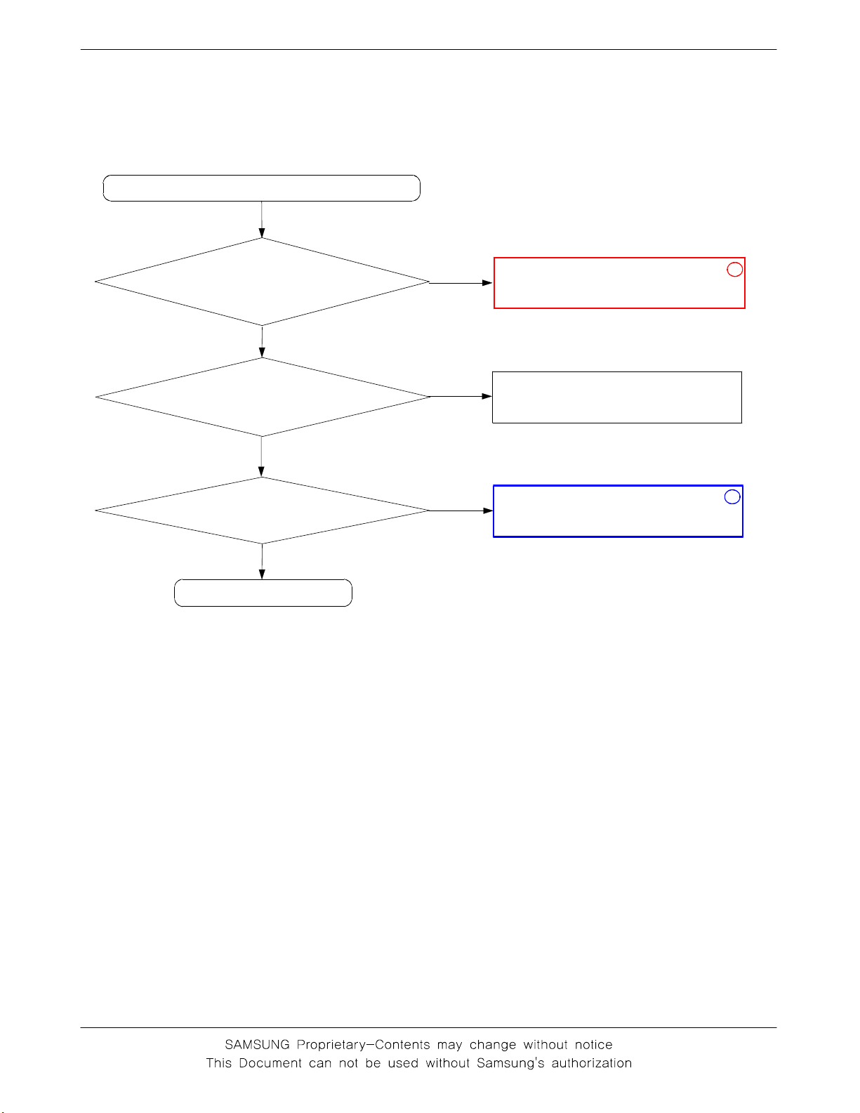
2-1-4.Microphone Part
* Call with Sim before testing.
MicroPhone does not work
SGH-X481 Flow Chart of Troubleshooting
Yes
Check the soldered
status of microphone
Yes
Check the reference
voltage on mic path
R418≒2.0V
Yes
Is microphone OK?
Yes
END
No
No
No
Resolder microphone
Resolder or change C423
Check U100
1
2
2-7
SGH -X481 Flow Chart of Troubleshooting
2-8
2-1-5. Speaker Part
There is no sound from speaker
SGH-X481 Flow Chart of Troubleshooting
Check the connection
status of LCD connector
CN200
Yes
Are there any signal at
the speaker pad on LCD
PCB?
No
Check R402, R403 of
U402. Voltage is≥1V?
Yes
END
No
Yes
No
1
reconnect CN200
Replace the speaker module
2
Check U500
2-9
SGH -X481 Flow Chart of Troubleshooting
2-10
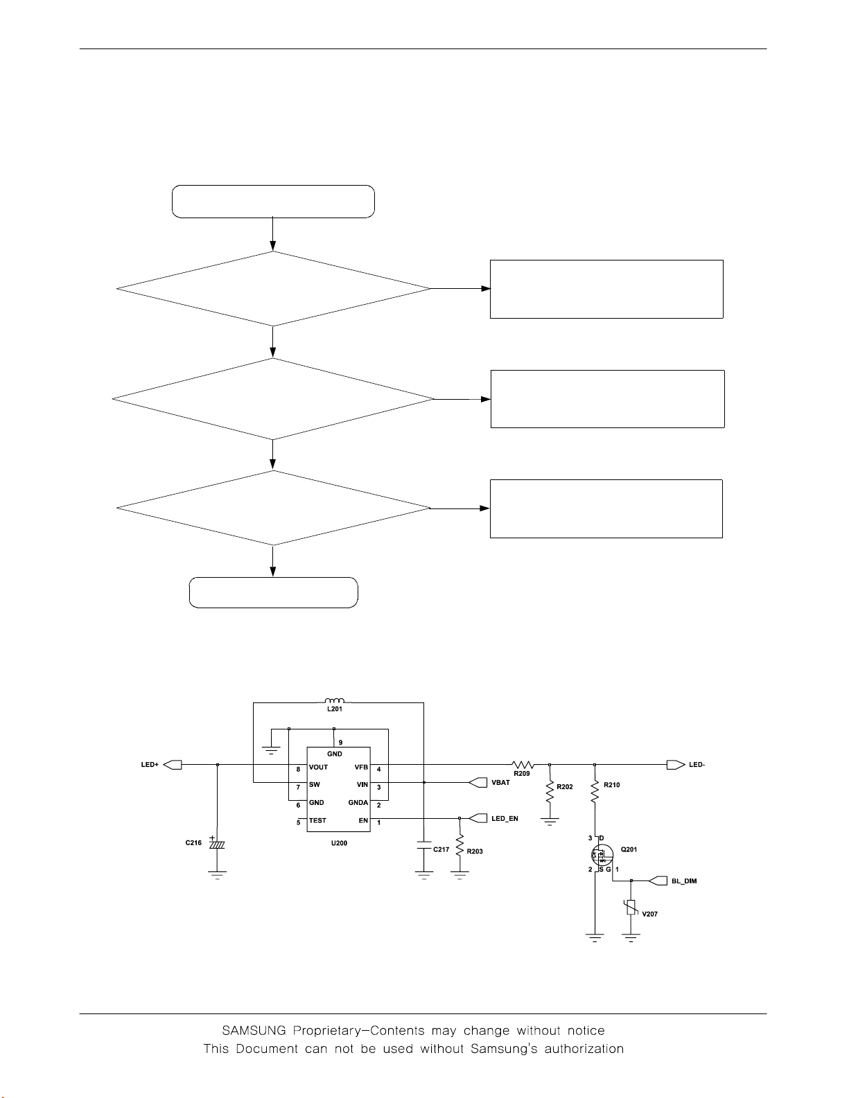
2-1-6. LCD backlight
Backlight does not work
SGH-X481 Flow Chart of Troubleshooting
Backlight ON "TIME"
mode in the menu?
Yes
Check conecting
between PBA and LCD
conector
Yes
Check U200 pin #8 =
10V ?
Yes
END
No
No
No
Select backlight "15 sec" mode
Check FPCB
Check the LCD
2-11
SGH -X481 Flow Chart of Troubleshooting
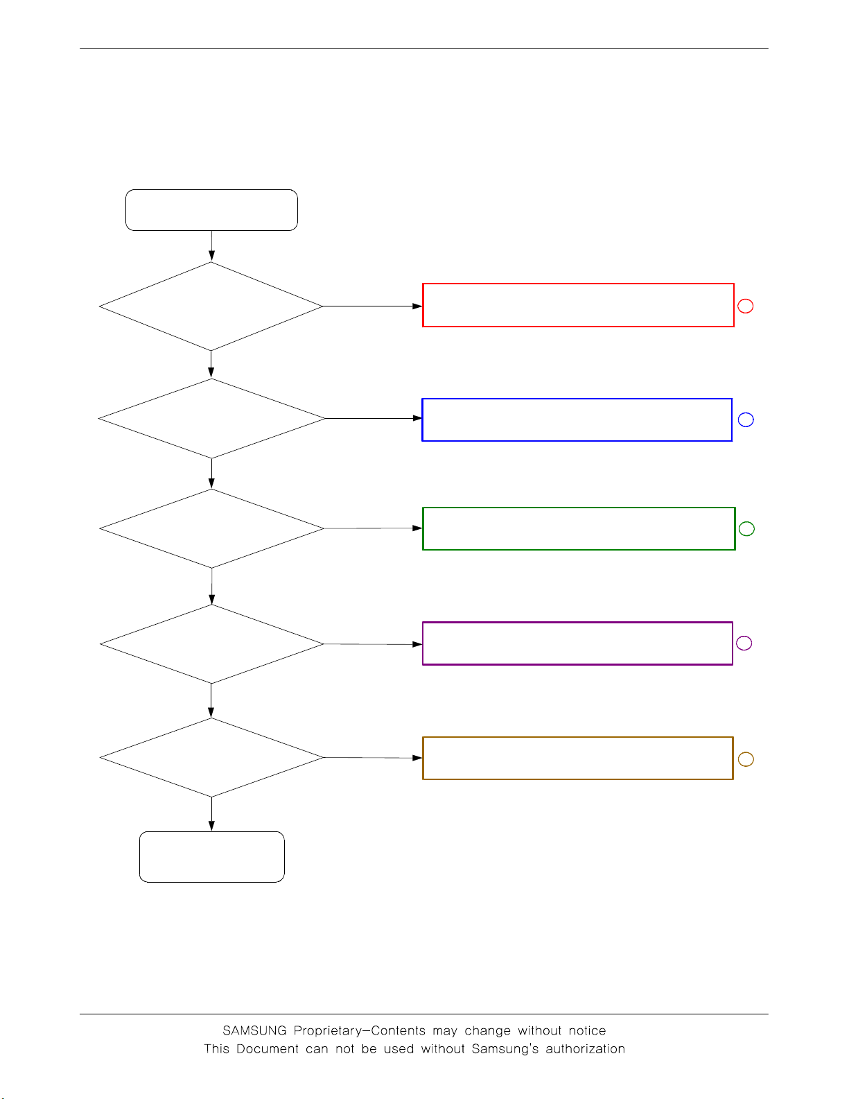
2-2. RF
2-2-1. GSM Rx
CONTINOUS RX ON
RF INPUT : 62CH
AMP : -60dbm
Normal condition
catch the
channel ?
Yes
Check U900
pin 12≥-65
dbm ?
Yes
Check U900
pin 16≥-65
dbm ?
Yes
Check U801
pin 21,22≥-
65dBm ?
Yes
No
No
No
No
Check ANT, C824,C825,C904,C903
Resolder or change
CON901, C903, L903, L904, C901, C902
Resolder or change
U900
Resolder or change
F900
1
2
3
4
Check U801
pin 13 = 2.9V
Yes
Resolder or change
U600
No
2-12
Resolder or change
U100
5
 Loading...