

Samsung SGH-X210 Schematics TSHOO
10.
Flow Chart of Troubleshooting
1. Baseband
10-
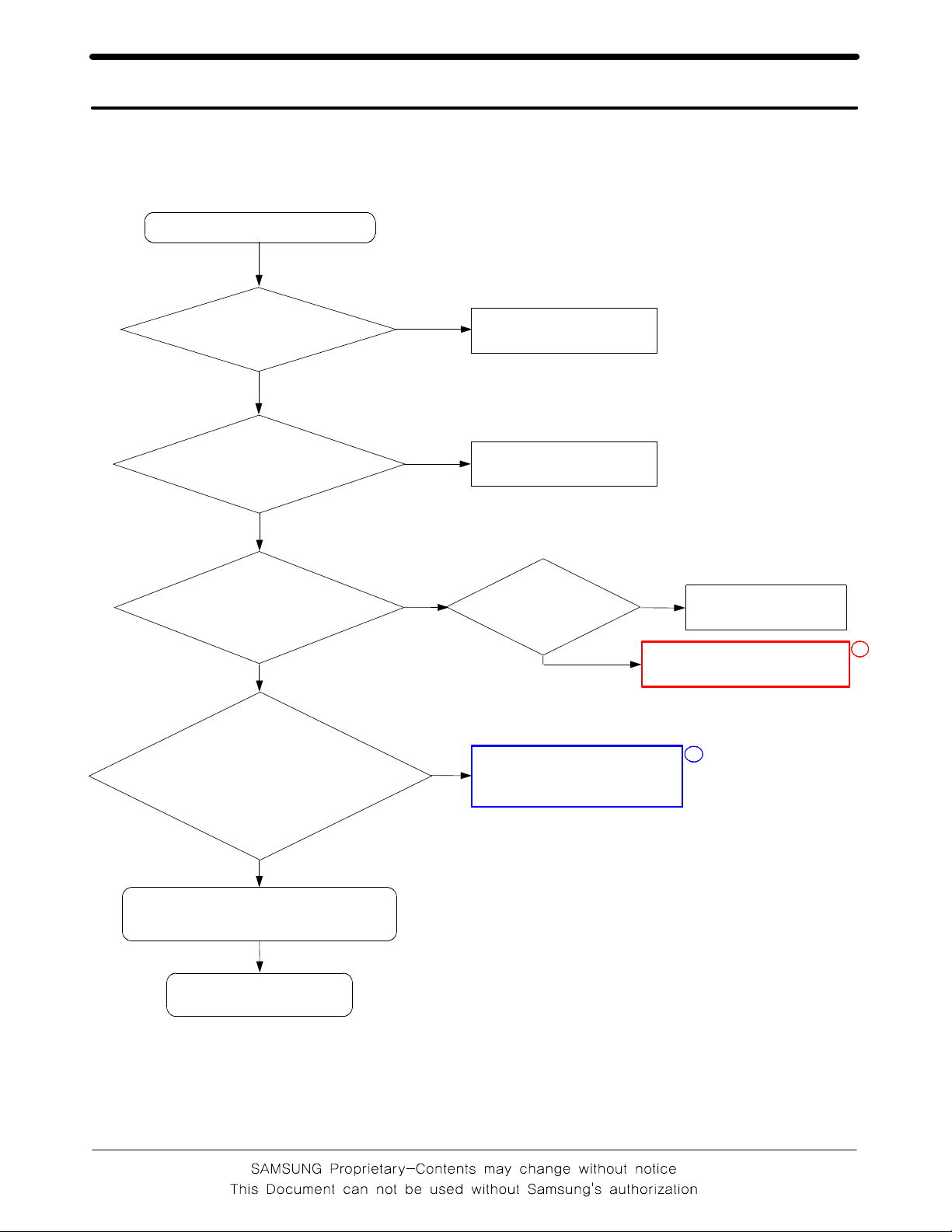
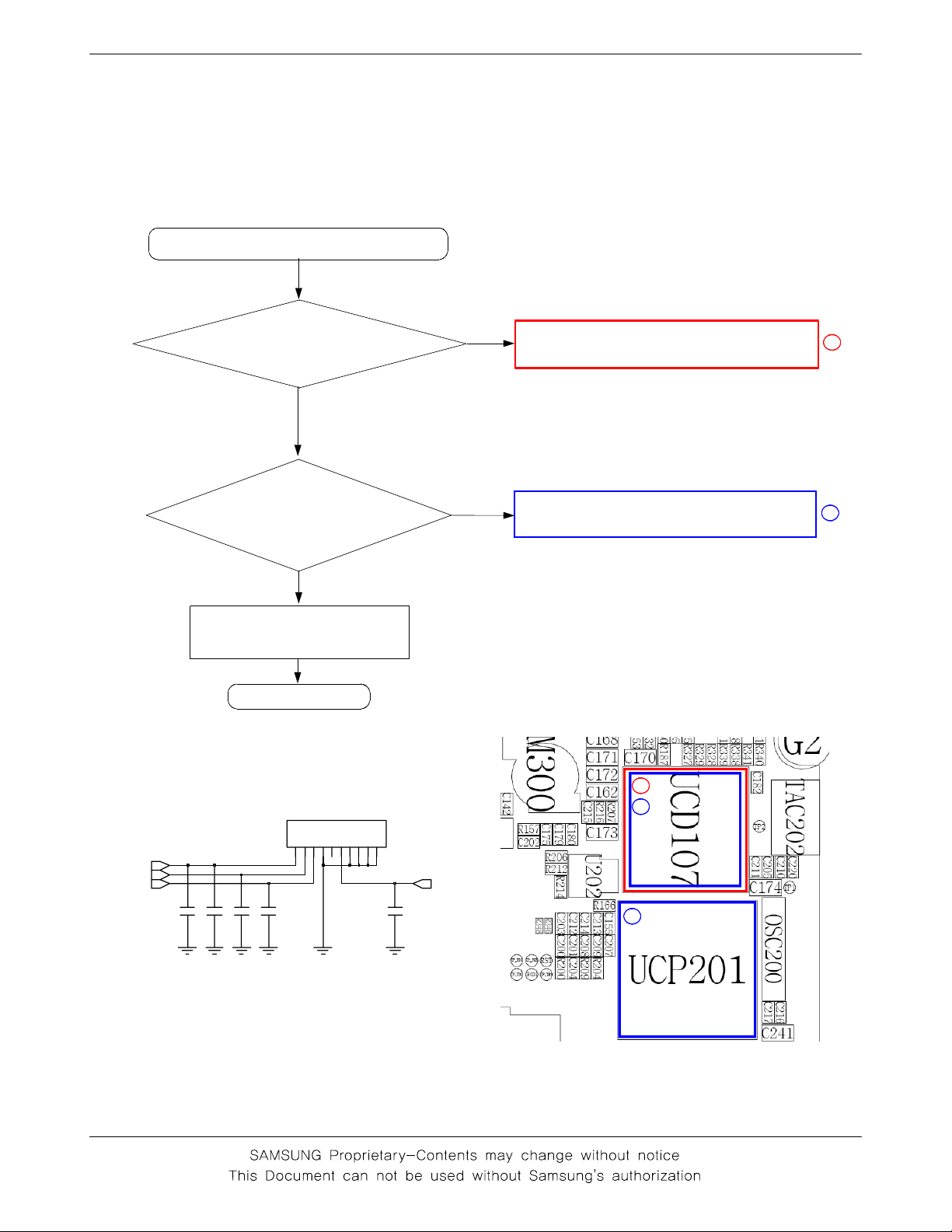
10-1-1. Power ON
'Power ON' does not work
check the current
consumption
>= 100mA
Yes
Check the Voltage
of the Battery
>= 3.3V
Yes
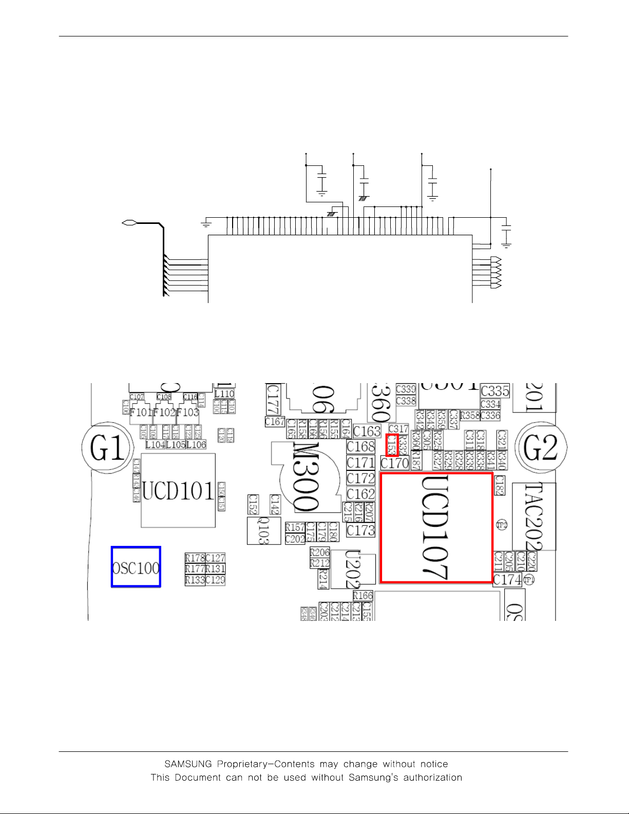
Check the pin C152,
C153,C155 of
UCP107 is >= 2.8V
>=2.8V
Yes
Check the clock signal
at pin #4 of OSC100
Freq=26Mhz,
No
No
No
No
Download again
Charge the battery
Check
"Power On"
key?
Check the clock generation
circuit OSC100
Yes
No
check keypad
1
check UCP107 and C153
2
Yes
Check the Initial Operation
Yes
END
10-1
Flow Chart of Troubleshooting
DSP_DB(0:15)
DSP_DB(15)
DSP_DB(14)
DSP_DB(13)
DSP_DB(12)
DSP_DB(11)
DSP_DB(10)
DSP_DB(9)
DSP_DB(8)
VCCD_2.9V
VCCA_2.9V
VCCD_2.9V
VBAT
C152
0
0
1
8
9
1
J
1
J
2
J
K
5
5
6
6
7
1
1
1
C
C
S
S
S
N
N
D
D
D
N
N
N
G
G
DB15
DB14
DB13
DB12
DB11
DB10
DB9
DB8
G
D2
D3
E3
E2
F3
F2
F1
F4
0
1
8
9
6
9
7
8
7
H
G
H
J
3
4
1
1
S
S
D
D
N
N
G
G
G
H
G
H
2
9
6
7
1
8
0
1
1
1
S
S
S
S
S
S
S
D
D
D
D
D
D
D
N
N
N
N
N
N
N
G
G
G
G
G
G
G
3
0
7
1
1
9
7
8
F
F
F
F
G
D
4
1
3
5
3
2
S
S
S
S
S
C
D
D
D
D
D
D
N
N
N
N
N
A
_
G
G
G
G
G
X
U
A
C153
0
1
3
1
1
4
6
4
1
6
1
F
B
A
L
P
C
L
L
V
V
B
T
T
D
D
D
C
C
N
D
N
O
O
V
G
G
_
_
D
D
N
D
V
G
5
1
4
2
6
M
B
D
D
V
4
N
K
R
P
G
J
2
3
4
1
D
D
N
G
2
D
S
S
S
S
O
D
I
S
S
S
S
D
_
V
V
V
V
V
D
D
V
C155
5
6
N
M
N
1
3
D
O
I
D
_
V
D
D
V
1
1
1
1
8
1
3
E
B
B
F
C
K
J
1
2
2
1
D
D
D
D
V
V
5
7
R
Q
6
C
C
D
U
D
C11
D
S
S
D
VDD34
C
N
D
P
P
V
H
_
_
_
D
D
D
N
N
N
G
G
G
J13
G
V
VDD12
N9
UP_CLK
R10
UP_RST
P10
UP_IO
J11
SIM_IO
K11
SIM_RST
K14
SIM_CLK
3
5
0
5
1
3
C162
SIMCLK
SIMRST
SIMDATA
SIM_IO
SIM_RST
SIM_CLK
②
①
10-2
Flow Chart of Troubleshooting
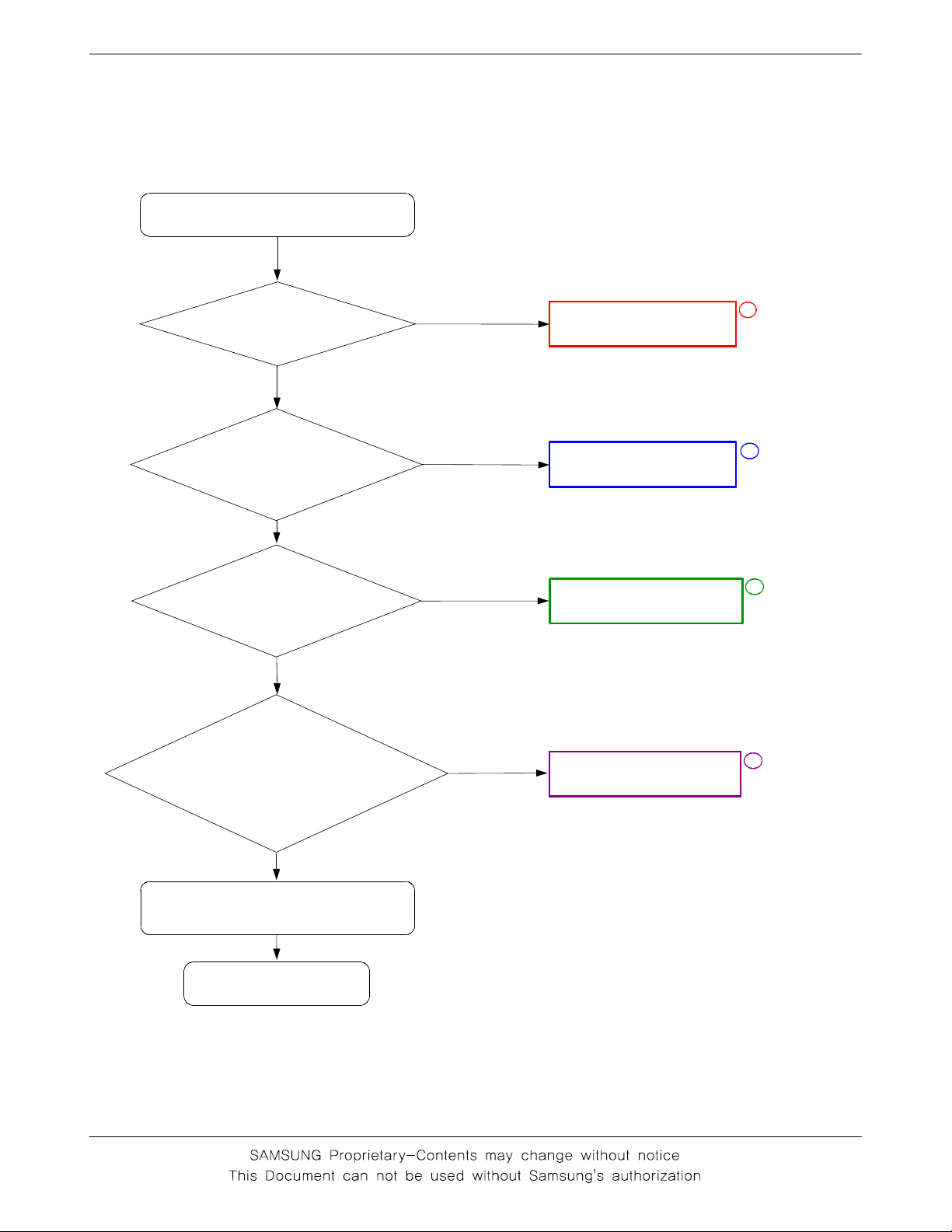
10-1-2. Initial
Initial Failure
check the pin
RSTB of UCP201
is LOW?
Yes
check the pin CKI
of UCP201 is
13Mhz?
Yes
Check the clock signal
at pin #3 of OSC100
Freq=26Mhz?
Yes
Check the pin #9 of
UCP107 is HIGH and pin
#11, #13 is 2.9V?
No
No
No
No
Check U201
Check
R177,R178,R131,C127
check OSC100
Check UCP107
1
2
3
4
Yes
Check the Initial Operation
Yes
END
10-3
Flow Chart of Troubleshooting
1
9
1
L
J
S
S
S
S
V
V
0
7
8
1
6
L
M
L
L
S
S
S
S
S
S
S
S
V
V
V
V
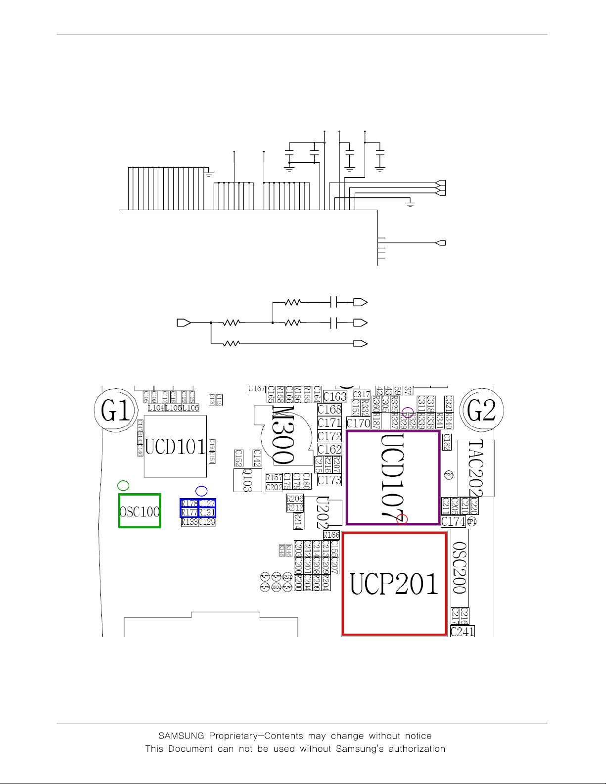
13M_OUT
VCCD_1.8V
VCCD_1.8V
VCCD_2.9V
0
1
1
7
6
1
7
7
K
K
H
J
H
G
S
S
S
S
S
S
S
S
S
S
V
V
V
V
V
6
7
6
9
3
2
6
F
A
A
G
S
S
S
S
S
S
S
S
V
V
V
V
3
1
1
5
1
1
C
R
A
R
T
S
D
D
D
D
S
D
D
D
D
V
V
V
V
V
4
1
1
4
1
2
B
R
R
G
E
E
D
D
D
D
D
D
D
D
D
D
D
D
V
V
V
V
V
V
7
1
E
C200
E
D
D
V
C201
6
6
5
6
1
1
1
1
8
E
N
U
U
P
E
E
E
E
D
D
D
D
D
D
D
D
V
V
V
V
6
5
1
1
2
1
1
U
M
B
E
G
L
E
E
E
E
L
D
D
D
D
P
D
D
D
D
D
V
V
V
V
_
S
S
V
R131
R177
R133
C127
C129
R178
VCCD_2.9V
1
0
0
1
1
1
C
E
F
L
F
A
A
L
E
S
D
P
R
S
D
D
V
V
V
_
X
D
D
V
7
8
1
D
F
C
T
R
V
VRTC_3V
C203
2
1
C
I
K
C
B
T
S
R
F12
TDO
F15
TRST
H12
TDI
G12
TMS
H13
TCK
CLK13M_TR
CLK13M_MC
CLK13M_YMU
C202
VREF
CLK13M_TR
TR_RST
TR_RST
4
3
2
1
10-4
Flow Chart of Troubleshooting
10-1-3. Sim Part
"Insert SIM" is displayed on the LCD
The voltage is 2.8V
at the pin#1 of SIM103
Yes
Is there any signal
pin #2,3,4 of SIM103?
Yes
Check the SIM Card
END
No
No
Check the UCP107
Check the UCP107 & UCP201
1
2
SIM103
D
C
C
P
K
N
L
C
C
V
C
G
V
2
5
3
4
1
VSIM
SIM_RST
SIM_CLK SIM_IO
C138 C139 C141 C142C140
C
C
C
C
P
O/I
V
N
N
N
N
9
6
7
8
0
1
1
2
2
10-5
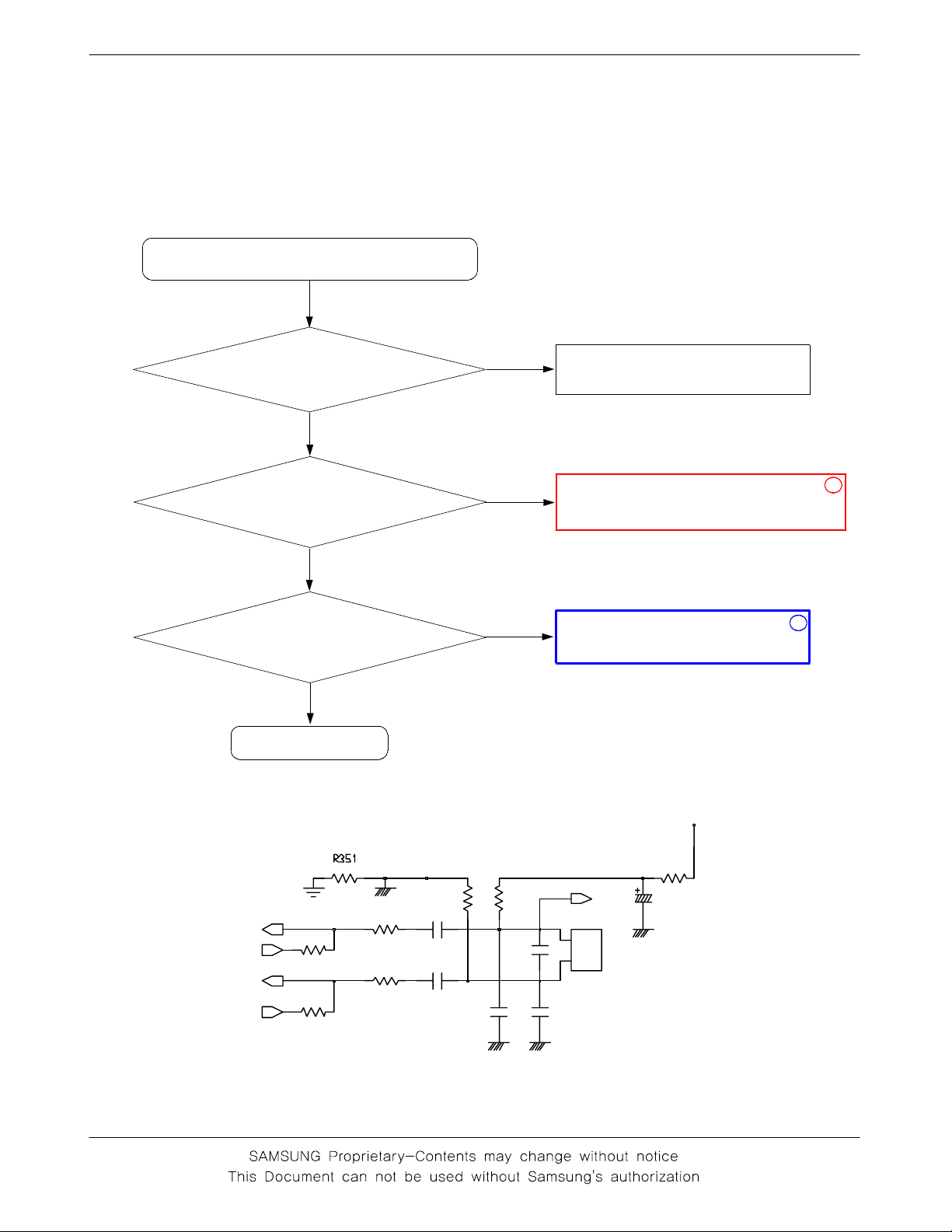
10-1-4.Microphone Part
* Call with Sim before testing.
MicroPhone does not work
Flow Chart of Troubleshooting
Yes
Check the soldered
status of microphone
Yes
Check the reference
voltage on mic path
R335≒2.0V
Yes
Is microphone OK?
Yes
END
No
No
R335,R336,R337,R338,R339,R340,R341,
Resolder microphone
Resolder or change
C318,C320,C321,C322,C323,C361
No
Check UCP107
1
2
MICINP
MICOUTP
MICINN
MICOUTN
R359
R364
R358
R363
C316
C322
R354
10-6
R355
C319
C327
C326
VCCA_2.9V
R353
MIC+
L301
1
1
2
2
C336
 Loading...