

Samsung SGH-S8000, GT-S8000 Disassembly & Reassembly
Disassembly and Assembly Instructions
11.
11-1.
Disassembly
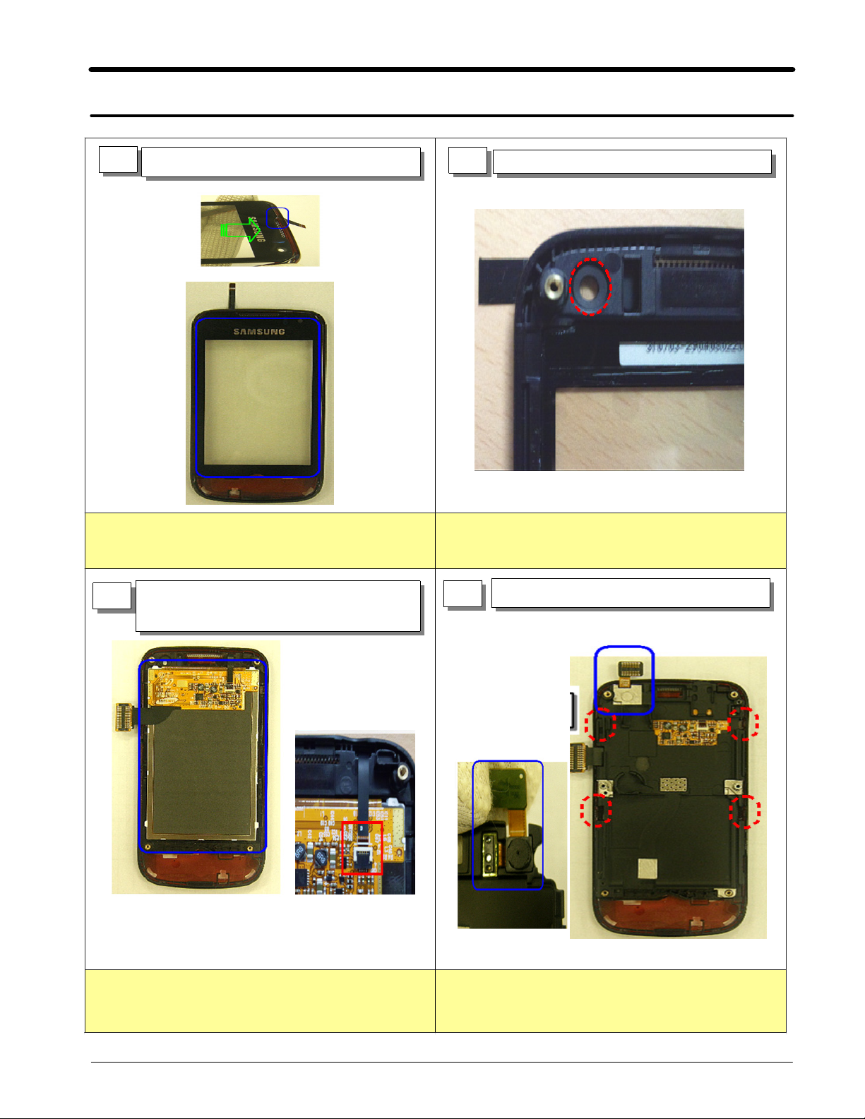
1
Place the Touch on the Front
2
Attach the VGA Camera Sponge
Place the touch on the front like the picture.
1.
Place the LCD module and Assemble
3
FPCB.
TSP
Attach the VGA Sponge on the position of the picture.
1.
4
Assemble
VGA Camera and Bracket.
1. Place the LCD module and Assemble
SAMSUNG Proprietary-Contents may change without notice
This Document can not be used without Samsung's authorization
TSP FPCB.
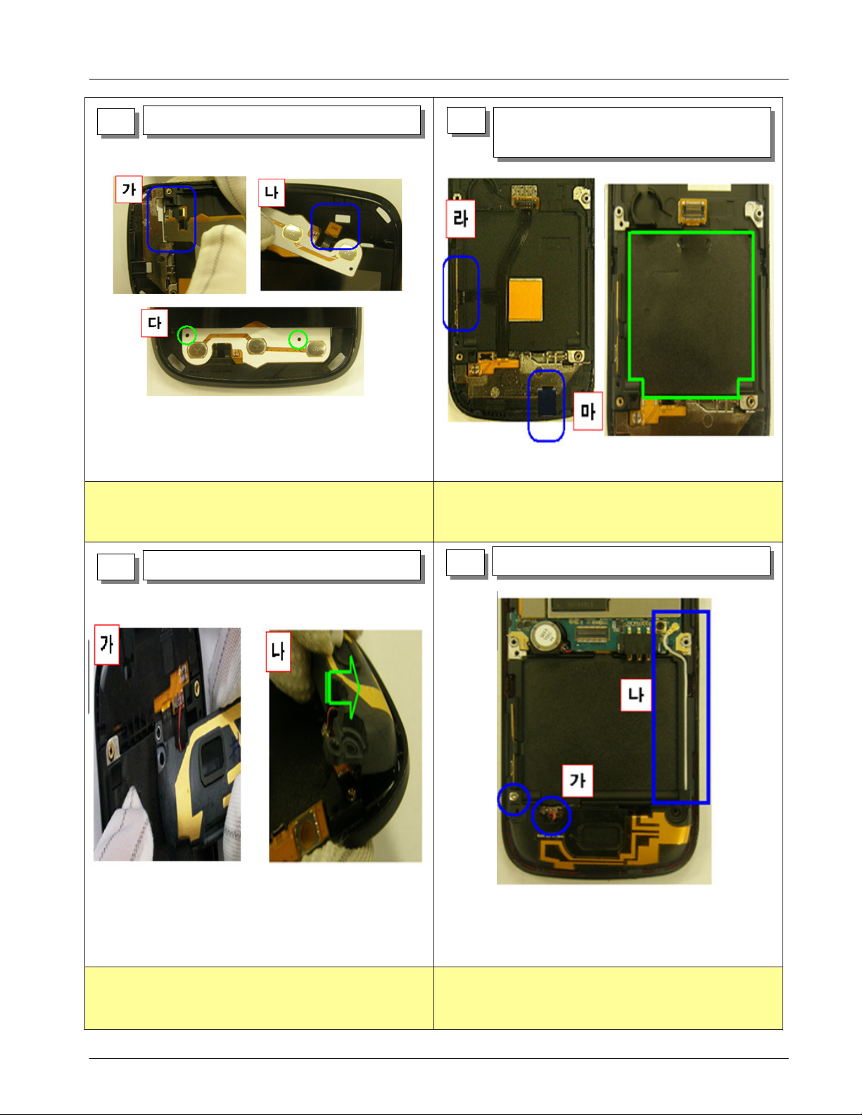
1. Assemble
Assemble the bracket with Front.(Red mark: HOOK
2.
point.)
11-1
VGA Camera on the Bracket.
Exploded View and Parts List
Assemble KEY FPCB
5
Assemble the KEY FPCB with Front using the guide
1.
line.
6
Attach MIC HOLDER and BATT BLACK
SHEET
Attach
1.
Camera SIDE KEY FPCB and assemble MIC
HOLDER.
2.Attache Battery BLACK SHEET.
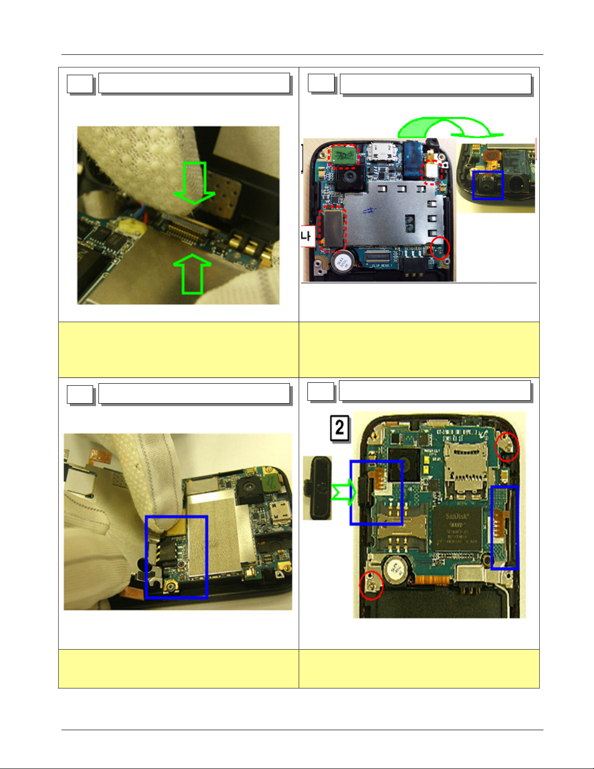
Connect Speaker Connector
7
Assemble Speaker
8
Connect the Speaker connector like picture and place
1.
the speaker by half turn.
SAMSUNG Proprietary-Contents may change without notice
This Document can not be used without Samsung's authorization
Assemble the Antenna wire like picture.
1.
Screw Torque:
2.
1.0 ~ 1.2
kgf.cm
11-2
Exploded View and Parts List
Assemble KEY FPCB Connector
9
Connect PBA and KEY FPCB.
1.
10
Place the
1.
Place the PBA
PBA and connect the VGA Camera
.
LCD connector, 3.5pi Receiver ASS'Y
connector
.
2.Place SUB MIC like picture.
connector
connector
,Antenna
,
Assemble SUB PBA
11
1.Connect SUB PBA and attach SIDE KEY FPCB.
Assemble hold KEY and skew 2 points.
12
Attach HOLD KEY.
1.
Screw2points like picture.(Screw Torque:
2.
kgf.cm)
1.0 ~ 1.2
11-3
SAMSUNG Proprietary-Contents may change without notice
This Document can not be used without Samsung's authorization
 Loading...