

Samsung SGH-i7110, GT-i7110 Disassembly & Reassembly
Disassembly and Assembly Instructions
11.
11-1.
Disassembly
1 2
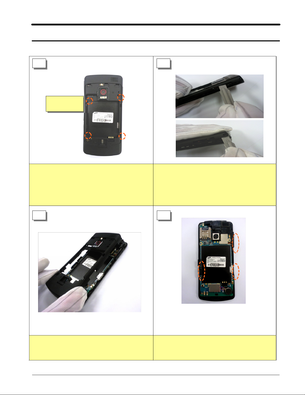
SCREW
Remove Screws
1)
Remove4Screws.
-
4
POINTS
Remove the Rear cover
1)
Useadecomposition tool to VOLUME KEY part
-
-1
and make gap between Front and Lear.
If turn over rear upper corner hanger part
backward usingadecomposition tool, upper locker
is disintegrated easily.
3 4
Remove the rear cover
1)
Lift the rear from the front with care.
-
-2
Remove2SIDE KEYs and IF COVER.
1)
11-1
SAMSUNG Proprietary-Contents may change without notice
This Document can not be used without Samsung's authorization
Disassembly and Assembly Instructions
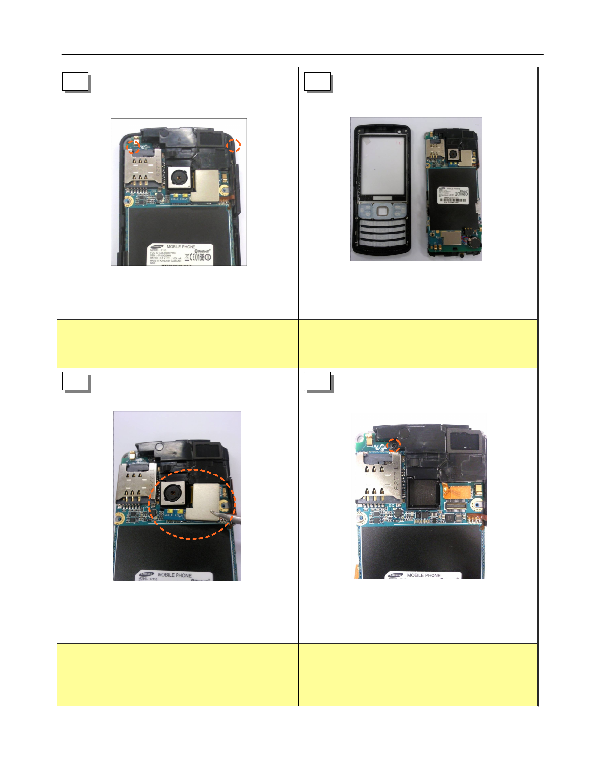
5 6
Remove Screws
1)
Remove2Screws.
-
7 8
Separate the FRONT from the PBA Assa'y.
1)
Separate the FRONT from the PBA Assay with care.
-
Separate the
1)
Separate
-
5M
CAMERA MODULE.
5M
CAMERA MODULE Connector from the
PBA Connector with care.
RemoveaScrew
1)
Removeascrew.
-
11-2
SAMSUNG Proprietary-Contents may change without notice
This Document can not be used without Samsung's authorization
Disassembly and Assembly Instructions
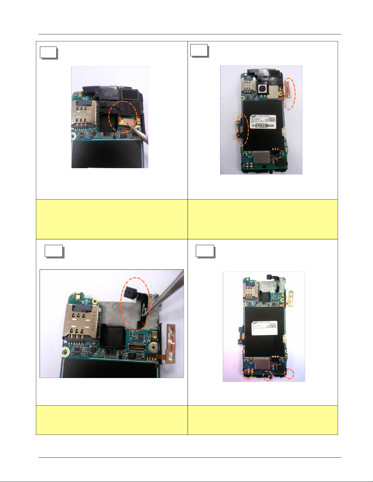
9
Separate the SPEAKER.
1)
Separate SPEAKER FPCB Connector from the PBA
-
Connector with great care.(Be careful not to tear Key
FPCB.)
10
Detach VOLUME KEY FPCB AND CAMERA KEY
1)
FPCB.
Detach2SIDE KEY FPCB from the main SHIELD
-
CAN with great care.
Be careful not to tear Key FPCB.)
(
11
Detach VGA CAMERA.
1)
Detach VGA Camera attached to the main shield can
-
with great care not to tear VGA Camera FPCB.
12
Separate PBA from3lockers.
1)
Separate PBA from3lockers.
-
11-3
SAMSUNG Proprietary-Contents may change without notice
This Document can not be used without Samsung's authorization
Disassembly and Assembly Instructions
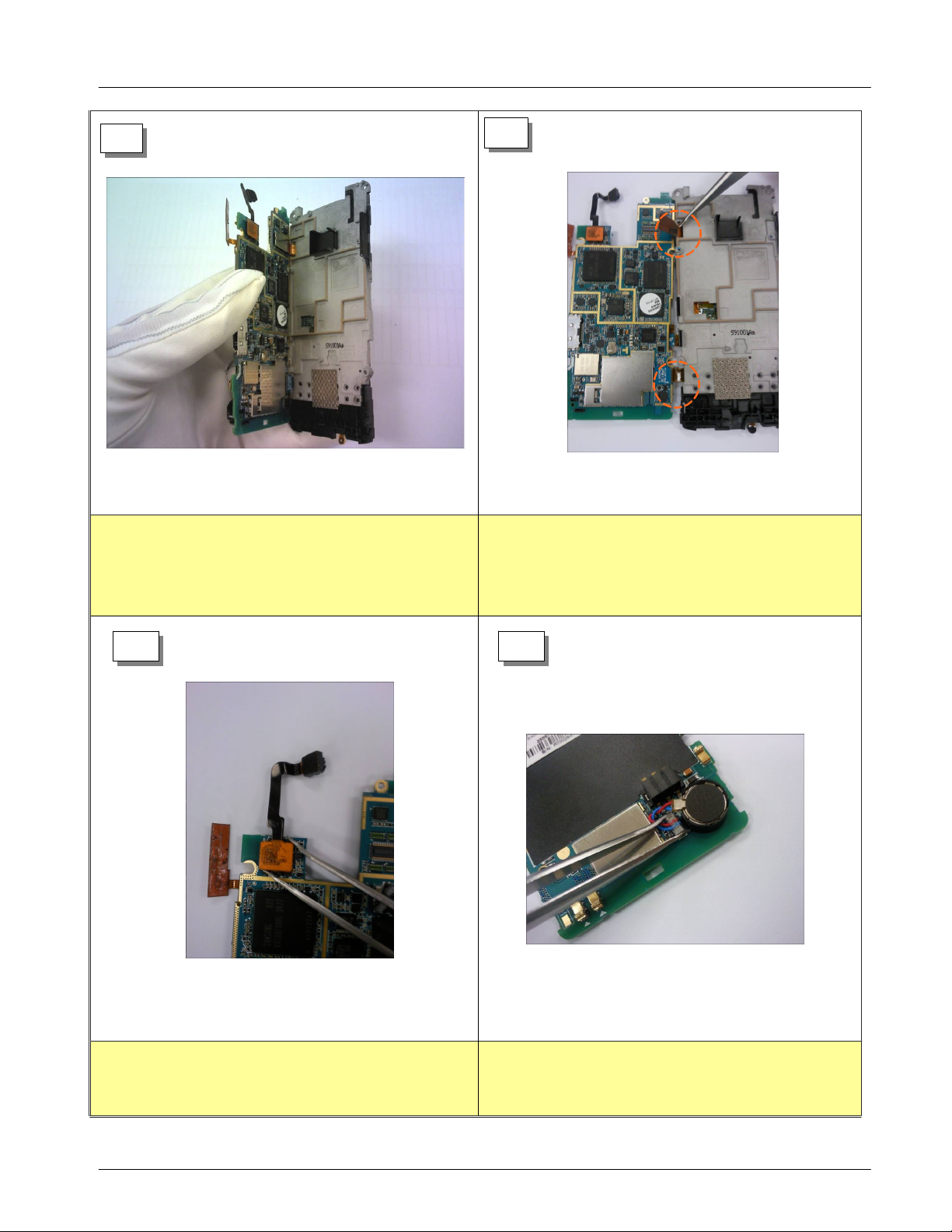
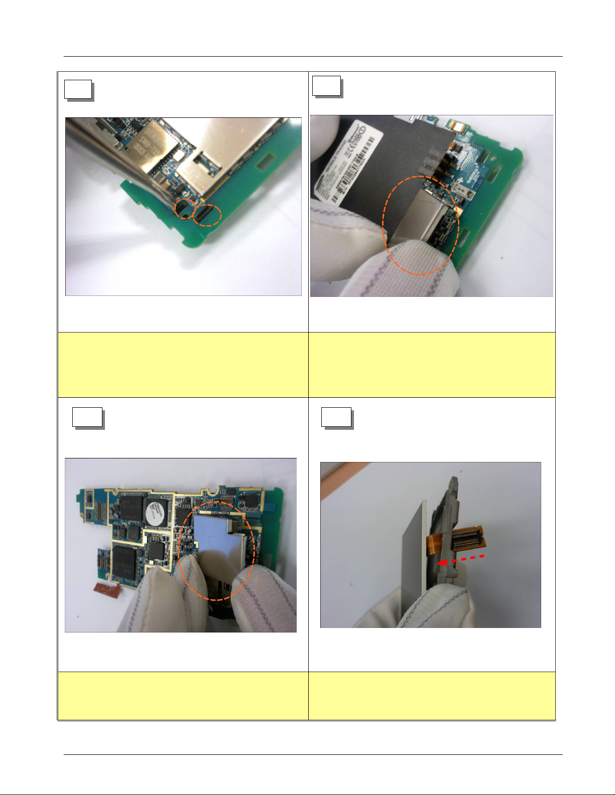
13
Separate PBA from the main shield can
1)
Separate PBA from the main shield can referring to the
-
above picture.
14
Separate LCD CONNECTOR and KEY CONNECTOR.
1)
Separate LCD Connector and KEY Connector from
-
PBA with care.
15
Separate VGA CAMERA.
1)
Separate VGA CAMERA connector from PBA.
-
16
Separate the MOTOR CONNECTOR.
1)
Separate the MOTOR CONNECTOR from PBA
-
connector with great care not to tear the wire.
11-4
SAMSUNG Proprietary-Contents may change without notice
This Document can not be used without Samsung's authorization
Disassembly and Assembly Instructions
17
Separate MOTOR from2lockers.
1)
Separate MOTOR from2lockers.
-
18
Remove RF Shield can from the PBA BOTTOM.
1)
Remove RF Shield can from the PBA BOTTOM.
-
19
Remove RF Shield can from the PBA TOP.
1)
Remove RF Shield can from the PBA TOP.
-
20
Separate LCD from the main shield can.
1)
Separate LCD from the main shield can.
-
11-5
SAMSUNG Proprietary-Contents may change without notice
This Document can not be used without Samsung's authorization
 Loading...