

Samsung SGH-A800, SGH-C200 optiflash

OPTIMAY
OptiFlash and CmdFlash Utilities
User Manual
Version 3.0
Optimay GmbH, a subsidiary of Agere Systems 15-Oct-02
Reference Platform Group Copyright © Optimay GmbH. All rights reserved
OptiFlash and CmdFlash Utilities
User Manual
Copyright © 2002 Optimay GmbH.
All rights reserved.
The use and copying of this product is subject to a license agreement. Any other use
is prohibited. No part of this publication may be reproduced, transmitted, transcribed,
stored in a retrieval system or translated into any language in any form by any means
without the prior written consent of Optimay GmbH. Information in this manual is
subject to change without notice and does not represent a commitment on the part of
the vendor.
Document Summary
Document Type User Manual
Document Title
Document Number 100-01-FMU
Version 3.0
Author Martin Lohse
Date 10-Oct-2002
OptiFlash and CmdFlash Utilities
Change History
Rev. Date Author Change
1.0 15-Oct-01 Lohse Initial edition
2.0 08-Jan-02 Lohse
3.0 10-Oct-02 Lohse
Added description of passive boatloader
protocol; made some minor corrections
Added new section on how to use the
OpiFlash DLL in user applications;
corrected various errors in the text.
OptiFlash and CmdFlash Utilities Page 2 of 27
Agere Systems Proprietary

Optimay GmbH, a subsidiary of Agere Systems 15-Oct-02
Reference Platform Group Copyright © Optimay GmbH. All rights reserved
Table of Contents
1 INTRODUCTION .............................................................................................................................4
2 OVERVIEW.......................................................................................................................................4
2.1 HOW IT WORKS ..................................................................................................................................4
2.2 BOOTLOADER TYPES..........................................................................................................................4
2.3 BASIC OPERATIONS............................................................................................................................5
2.3.1 Flash mode................................................................................................................................5
2.3.2 Verify mode................................................................................................................................5
2.3.3 Read mode.................................................................................................................................5
2.4 A NOTE ON S-RECORD FILES ..............................................................................................................5
3 USING OPTIFLASH.........................................................................................................................6
3.1 THE SETTINGS WINDOW .....................................................................................................................6
3.1.1 Settings/General........................................................................................................................7
3.1.2 Settings/COM Port ....................................................................................................................9
3.1.3 Settings/Flash & Verify ...........................................................................................................10
3.1.4 Settings/Read...........................................................................................................................11
3.2 THE LOG WINDOW............................................................................................................................12
3.3 PROFILES .........................................................................................................................................12
3.4 ERRORS ...........................................................................................................................................12
4 USING CMDFLASH.......................................................................................................................14
5 TIPS AND TRICKS.........................................................................................................................16
5.1 USING TWO PORTS IN PARALLEL ......................................................................................................16
5.2 WHAT TYPE OF BOOTLOADER? ........................................................................................................16
5.3 TROUBLES FLASHING THE PHONE?...................................................................................................17
5.4 GENERATING COMMAND LINE OPTIONS ...........................................................................................17
5.5 REPORTING PROBLEMS ....................................................................................................................17
6 USING OPTIFLASH IN YOUR OWN APPLICATION.............................................................18
6.1 THE FUNCTIONS...............................................................................................................................18
6.1.1 Main functions.........................................................................................................................18
6.1.2 Helper functions ......................................................................................................................18
6.2 THE STRUCTURES.............................................................................................................................20
7 BOOTLOADER PROTOCOL.......................................................................................................21
7.1 PASSIVE BOOTLOADER..................................................................................................................... 21
7.1.1 Initial setup phase ...................................................................................................................21
7.1.2 Command phase......................................................................................................................23
7.1.3 Synchronisation.......................................................................................................................23
7.1.4 Command loop ........................................................................................................................23
7.1.5 Command format.....................................................................................................................25
7.1.6 Response format......................................................................................................................25
7.1.7 Bootloader commands.............................................................................................................26
OptiFlash and CmdFlash Utilities Page 3 of 27
Agere Systems Proprietary

Optimay GmbH, a subsidiary of Agere Systems 15-Oct-02
Reference Platform Group Copyright © Optimay GmbH. All rights reserved
1 Introduction
Transferring code and data to or from a mobile phone requires a special program.
Optimay provides two utilities for this purpose: the GUI-based “OptiFlash”, intended
for interactive use; and the command-line driven “CmdFlash”, intended for use in
batch files and Perl scripts. The utilities share a common functionality, and it may be
assumed that–unless otherwise stated–anything said about OptiFlash applies equally
to CmdFlash.
These tools are intended for use in a development, not a production environment.
The requirements for these two different environments differ greatly. Refer to section
7, "Bootloader protocol", for a description of the communication protocol
implemented in the boot loader. This can be used to implement a flash loader
suitable for production needs.
2 Overview
2.1 How it works
When the phone is switched on, the bootloader code in ROM checks whether
OptiFlash is connected to the phone and is trying to “flash” it. If OptiFlash is not
connected, the bootloader starts the protocol stack software.
Otherwise OptiFlash and the bootloader establish communication. To use the clientserver terminology, the phone acts as a server, which runs in a loop and accepts
commands from OptiFlash, the client.
Because space in ROM is scarce, and because ROM code/data is difficult to change,
the bootloader is kept small and simple. It understands just sufficient commands to
be able to load data into the phone’s RAM. After establishing communication with
the phone, the first thing OptiFlash does is to use the bootloader to download a socalled ‘flash loader’ to the phone’s RAM. This is the program that provides all the
necessary functions to erase and/or program the flash memory on the phone. Again,
this code will act as a server, accepting commands from OptiFlash. Since there are
many different flash chips from various manufacturers, all of which differ in their
sector layout and capabilities, the flash loader does not contain much information
about specific chips. It is merely capable of detecting the flash chip type and of
programming the chip. All the details about the chip are handled on the PC side by
OptiFlash, which is aware of the sector layout and other idiosyncrasies of the chips.
2.2 Bootloader types
There are two different types of bootloader communication protocol implemented in
the ROM of Trident chipsets: active and passive. The names indicate whether the
phone initiates the communication (active) or waits for OptiFlash to initiate the
communication (passive).
The active bootloader initiates communication with the PC by sending a special bytesequence to the serial port when the phone is switched on. If OptiFlash is connected
and wants to “flash” the phone, it recognises this sequence.
OptiFlash and CmdFlash Utilities Page 4 of 27
Agere Systems Proprietary

Optimay GmbH, a subsidiary of Agere Systems 15-Oct-02
Reference Platform Group Copyright © Optimay GmbH. All rights reserved
The passive bootloader merely listens to the serial ports for a short period of time. If
it detects a special character, it assumes that OptiFlash is connected and wants to
“flash” the phone. The advantage of the passive approach is that other data
applications are not confused by receiving unexpected characters from the serial
port.
To determine which type of bootloader is in a particular phone, refer to section 5.2,
"What type of bootloader?". The passive bootloader is built into all new chipsets;
the active bootloader is currently being phased out.
2.3 Basic operations
OptiFlash supports three modes of operation: flash, verify and read.
2.3.1 Flash mode
In this mode the contents of an S-record file (SRE for short) are loaded into the flash
memory of the phone. It is used to apply software updates to the phone.
2.3.2 Verify mode
In this mode the contents of an SRE file are compared with the contents of the
appropriate memory ranges in flash memory of the phone. This is a convenient and
fast way to check whether the phone contains the correct software or data.
2.3.3 Read mode
This mode is used to read memory ranges from the flash memory on the phone into
an SRE file on the PC. This is useful for backing up important data which is phoneor user-specific (e.g. calibration data, phonebook data).
2.4 A note on S-record files
OptiFlash expects that all files it handles will be in Motorola S-record format . All files
written by OptiFlash are in this format.
A SRE file is an ASCII file containing addresses and data in hexadecimal form,
guarded by a checksum byte at the end of each row. Conventionally, the filename
extension is ‘.sre’. The user does not need any deeper knowledge about SRE files,
but it is useful to understand some basics about this format.
Since the SRE contains not only data but also the addresses where this data should
be written to or read from, the data in the file constitutes multiple regions in
consecutive memory. When loading a SRE file OptiFlash will check that all memory
addresses are in ascending order and that the memory regions are not overlapping
(which would lead to overwriting of content).
If both software and data need to be downloaded to the phone, the two SRE files can
simply be concatenated in the correct order and the resulting single SRE file flashed
into the phone.
OptiFlash and CmdFlash Utilities Page 5 of 27
Agere Systems Proprietary
Optimay GmbH, a subsidiary of Agere Systems 15-Oct-02
Reference Platform Group Copyright © Optimay GmbH. All rights reserved
3 Using OptiFlash
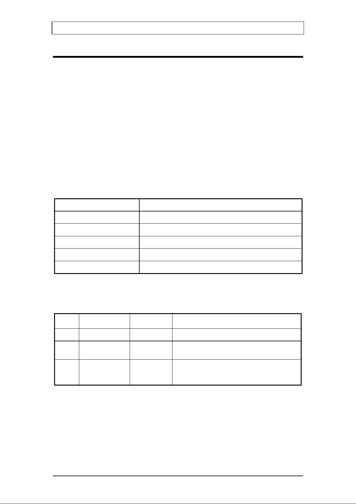
This is the main window of OptiFlash:
The file name shown is that of the file that will be loaded/verified. This can be
changed via Options/Settings (see below) or via "Drag & Drop". The list box contains
a history of the most recently used files. The history is maintained on a per-profile
basis (see section 3.3, "Profiles"); i.e. every profile has its own history list that is
independent of the other profile history lists.
There are four buttons, three for the basic operations OptiFlash supports, and a
fourth one to cancel the operation currently in progress (greyed out in this picture).
Once you have made all the necessary settings for your intended operation, you
merely have to click the appropriate button. OptiFlash now initializes the operation.
This may take a few seconds, depending on the chosen operation and on the size of
the involved SRE files. When OptiFlash is ready, it prompts you to switch on the
phone by displaying the message “Power on mobile”. Do not power on the phone
before that prompt is displayed, otherwise the communication setup will fail.
The currently used COM port(s) are shown in the lower right corner of the window.
3.1 The settings window
The most important menu item is the settings window, which can be reached via
Options/Settings from the main window.
The settings window consists of four different tab sheets, which are explained below.
OptiFlash and CmdFlash Utilities Page 6 of 27
Agere Systems Proprietary
Optimay GmbH, a subsidiary of Agere Systems 15-Oct-02
Reference Platform Group Copyright © Optimay GmbH. All rights reserved
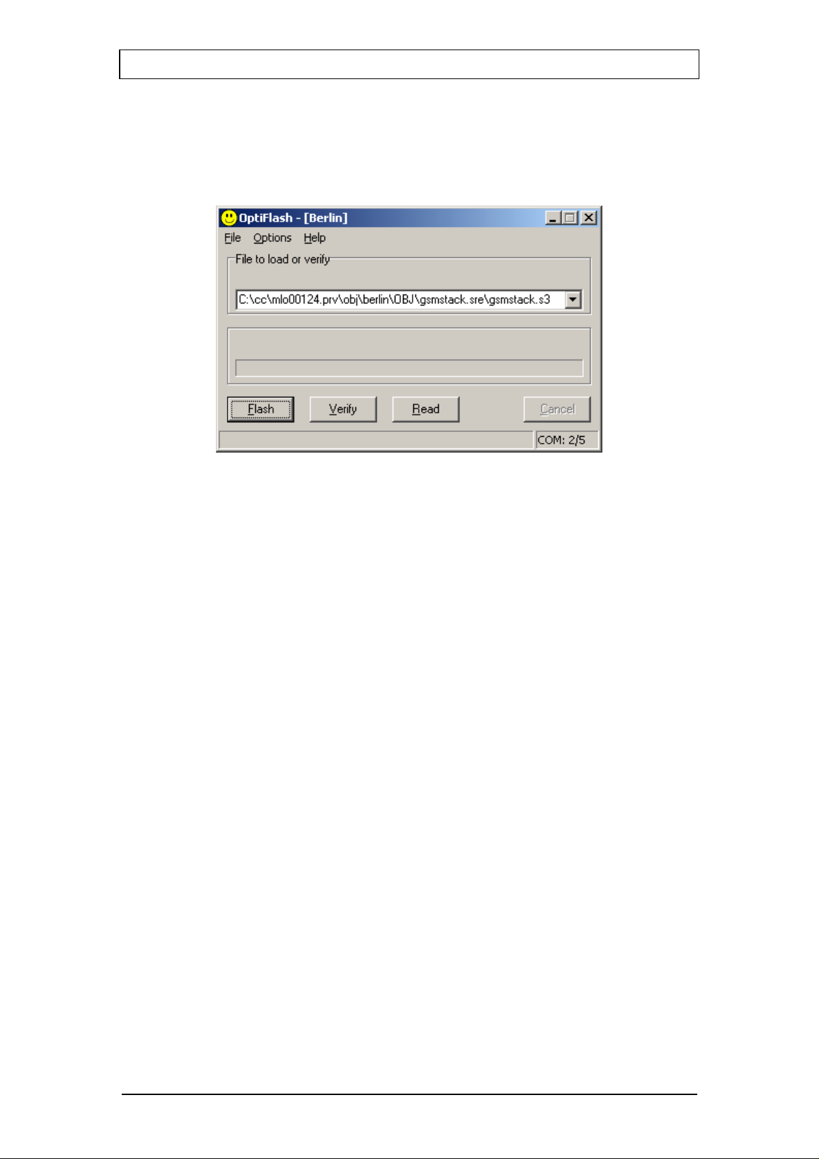
3.1.1 Settings/General
On this tab sheet all the general settings can be selected.
Specify hardware platform
Here you specify the type of hardware you want to flash/verify/read. This is the
most important setting, as this describes various details of the hardware to
OptiFlash. If you select an incorrect platform here, it is very likely that OptiFlash
will not be able to communicate with the platform.
The parameters needed to flash the MS are stored in a platform definition file
(platform.def) which is supplied by Optimay.
Flash erase passes
This setting specifies how many times a flash sector should be erased (1..8). It is
supplied for debugging purposes–the number of passes should be set to 1 for
normal operation. A higher number does no harm (apart from reducing the life of
the flash chip), but consumes considerably more time.
Operation phases
This option is for special development purposes. It must be set to Default for
normal operation. The other two settings determine which phases of the loading
process will be executed. When Stop after BL is selected, OptiFlash will load the
currently selected flash loader into the phone and will then exit. When Start at FL
is selected, OptiFlash will assume that a flash loader is already loaded into the
phone and will start sending commands to it.
Debug mode
Enabling debug mode causes additional information to be written to the log
window. If you are experiencing problems while flashing a phone and want
assistance from Optimay, it is absolutely essential to have this option enabled and
to send the resulting log file to Optimay.
OptiFlash and CmdFlash Utilities Page 7 of 27
Agere Systems Proprietary

Optimay GmbH, a subsidiary of Agere Systems 15-Oct-02
Reference Platform Group Copyright © Optimay GmbH. All rights reserved
Differences only
This option allows for more efficient data transfer. When enabled, OptiFlash
checks every sector that would be affected by the currently selected SRE file. If
the sector has the same contents as those specified by the SRE file it is not
changed, thus saving the time for required for programming the flash memory .
Extended protection
Enabling this option reduces the probability of a break in the serial-link
communication causing corrupted data in a flash sector. When new data has to
be added to a sector which already contains data, then the old data must be
merged with the new data before the sector is erased and rewritten. If extended
protection is disabled the sequence of events is:
1) Make a copy of the flash sector in RAM.
2) Erase the sector.
3) Download the new data and merge into the RAM copy.
4) Write the RAM copy back to the sector.
If extended protection is enabled, the sequence is changed to:
1) Make a copy of the flash sector in RAM.
2) Download the new data and merge into the RAM copy.
3) Erase the sector.
4) Write the RAM copy back to the sector.
Since in this case the flash loader has all the required data before it starts to make
changes to the flash, the danger of corruption is much less.
No retries
Normally, when a command times out before being executed, it is retried several
times. When this option is enabled, no retries are attempted and the operation is
terminated immediately with an error.
OptiFlash and CmdFlash Utilities Page 8 of 27
Agere Systems Proprietary
Optimay GmbH, a subsidiary of Agere Systems 15-Oct-02
Reference Platform Group Copyright © Optimay GmbH. All rights reserved
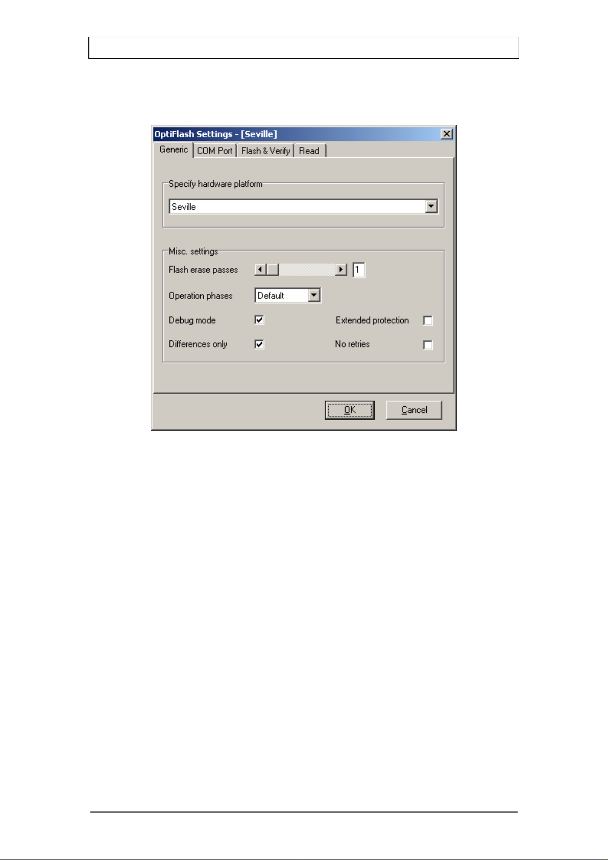
3.1.2 Settings/COM Port
This tab sheet is used to select the COM ports.
Up to twelve ports are supported. Additionally you can select the maximum transfer
speed OptiFlash will use to communicate with the phone. However, OptiFlash will
use a slower speed if either the PC’s or the phone’s serial hardware is incapable of
handling the selected speed.
You can set up to two COM ports. The first COM port is mandatory and is used to
transfer the flash loader to the phone. If a second COM port has been specified
(optional), then OptiFlash will use this COM port as well as the first one to
communicate with the flash loader, thus increasing the transfer speed. If the second
COM port is not specified, all communication is done using the first COM port.
The reason for having two different COM ports results from idiosyncrasies of
USB/serial adapters. They impose some latency in the serial communication that will
exceed timeout values in active boot loaders. The trick is to transfer the flash loader
into a phone with an active boot loader over the first COM port using a normal serial
cable. Then to benefit from the higher transfer speeds of the USB/serial converter,
the rest of the communication is done over the second COM port. This scenario is
only necessary for phones with an active boot loader; phones with a passive boot
loader should be able to cope with the communication latencies.
The speed increases you will experience when you use two COM ports in parallel is
highly dependant on the PC used, the current workload on the system, the quality of
the serial kernel drivers, etc.
OptiFlash and CmdFlash Utilities Page 9 of 27
Agere Systems Proprietary
 Loading...