

Samsung SGH-A400 Troubleshooting
SAMSUNG Proprietary-Contents may change without notice
5-1
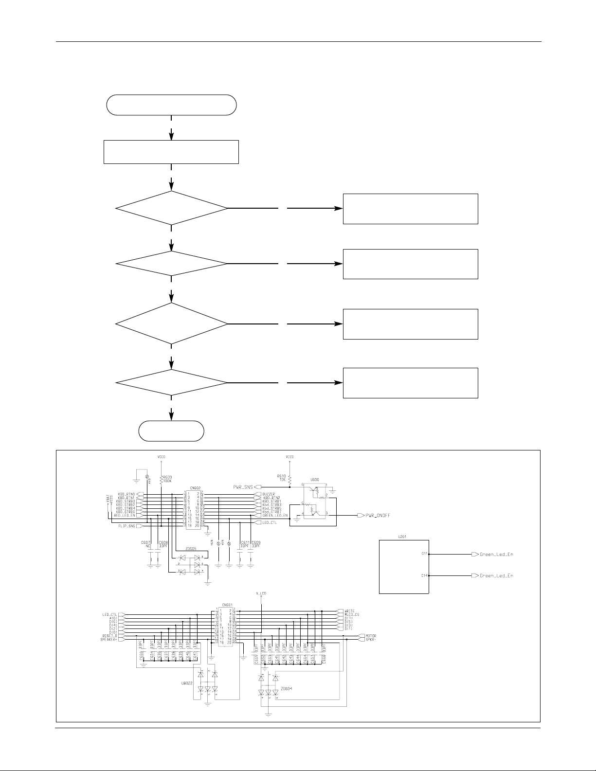
5.Flow Chart of Troubleshooting and Circuit Diagram
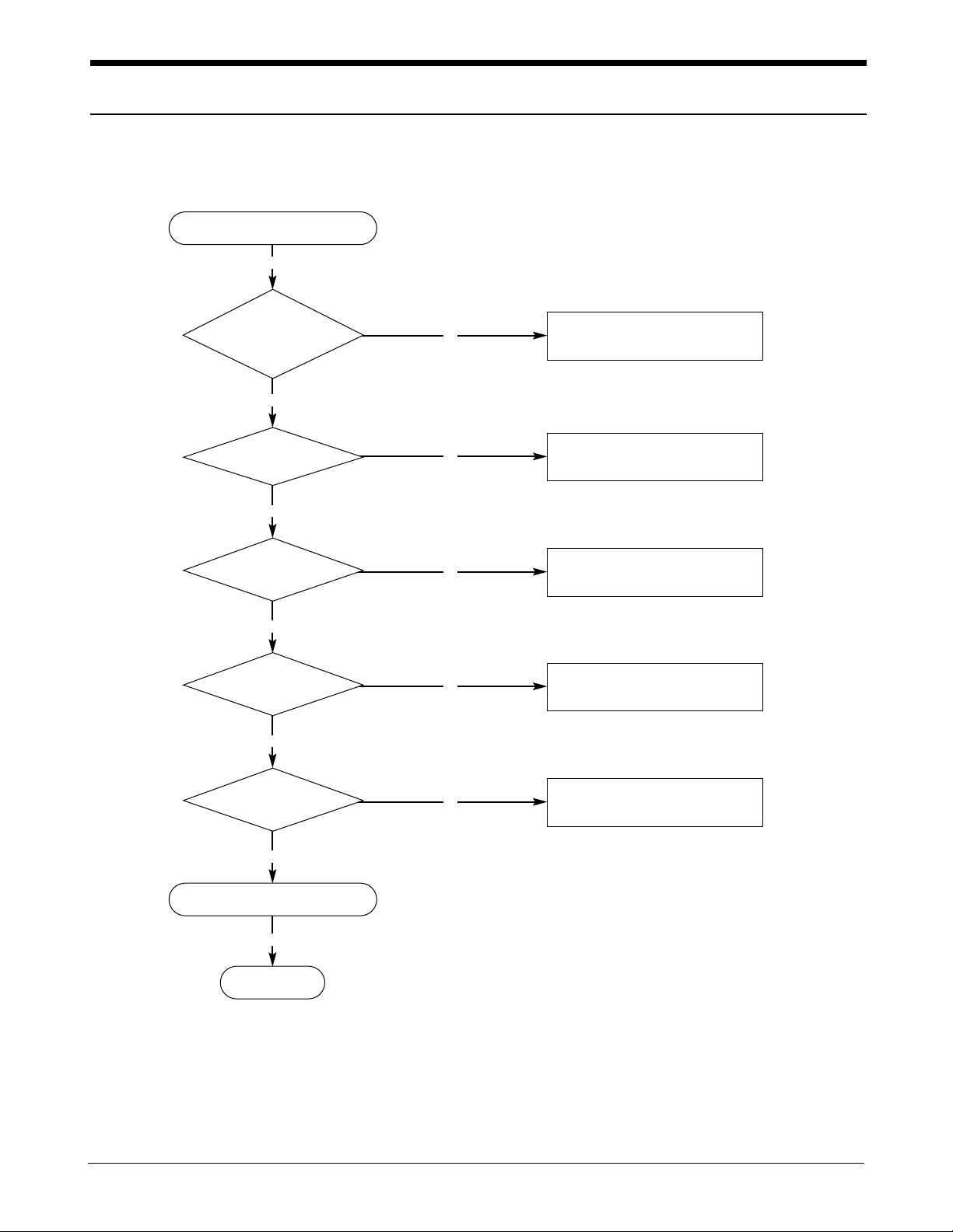
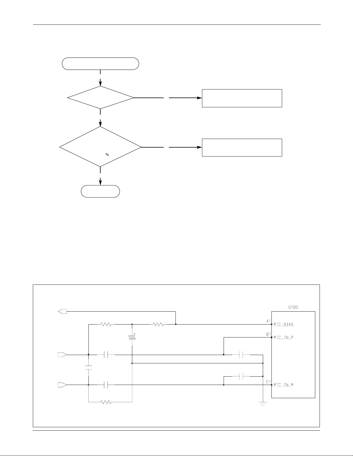
5-1 SGH-A400 Power ON
N
‘POWER ON’ does not work
Y
Y
Check the current
consumption more than
100 mA
Download again
N
Y
Check the
Battery Voltage more
than 3.3V
Charge the Battery
N
Y
Check the pin
38 of U400 is more than
3.2 V
Check to the path from CN604 to pin
38 of U400 and keypad
N
Y
U400 pin 33,28,30
= 2.8V
Change U400
N
Y
END
Y
Check the clock signal
at R105
Check the clock generation circuit
(related to U400 and OSC100)
Check the initial operation
SAMSUNG Proprietary-Contents may change without notice
5-2
SGH-A400 Flow Chart of Troubleshooting and Circuit Diagram
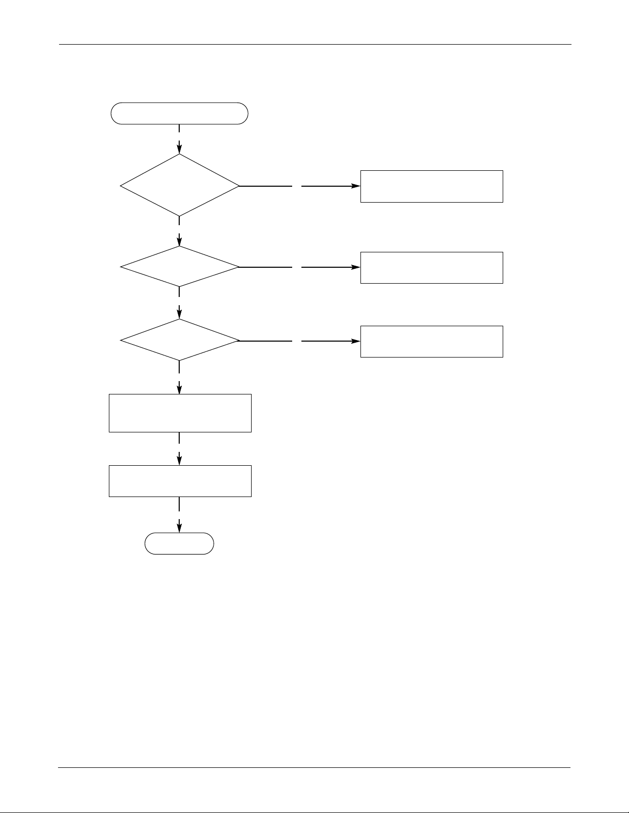
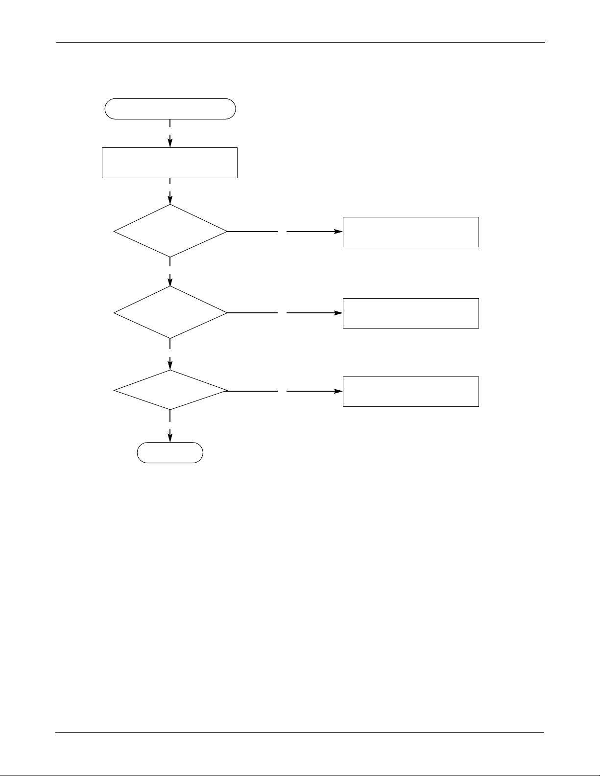
5-2 SGH-A400 Initial
N
Initial Failure
Y
Y
Check the “Reset_B”
signal at the pin 6 of
U8016 is “High”
Check the U100 (IA)
N
Y
Check the pin 10
of U400 is “High”
Check the U201 (M46)
N
Y
Check the pin 11 of U400
is “High”
Check the U400 (PMIC)
Y
Check the connections and
initialization using Factory
Test Program
END
Y
Check LCD connector CN601,
and resolder bridge
SAMSUNG Proprietary-Contents may change without notice
5-3
SGH-A400 Flow Chart of Troubleshooting and Circuit Diagram
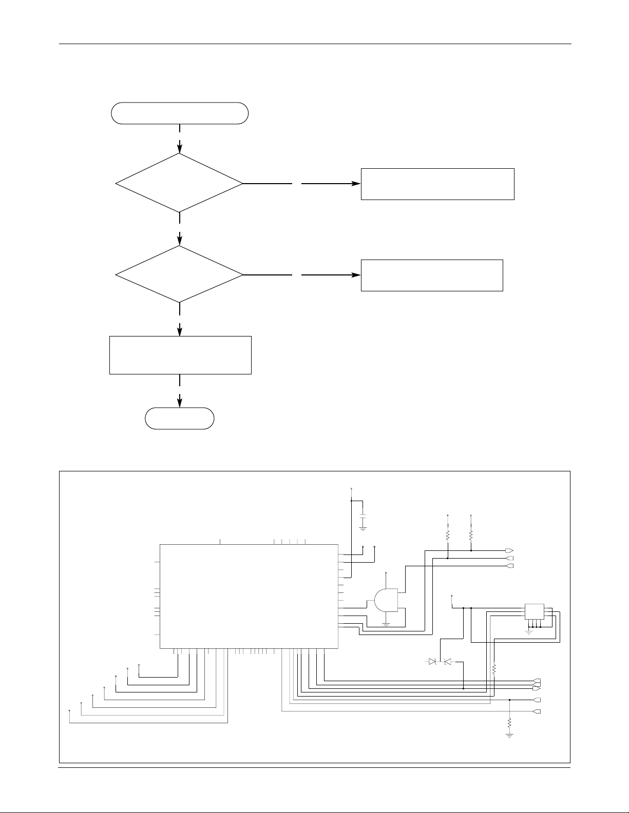
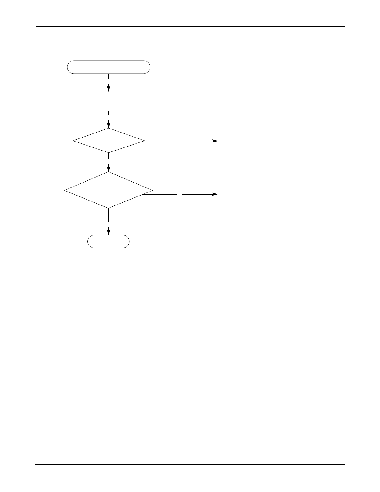
5-3 SGH-A400 Sim Part
Phone can’t access SIM card
Y
N
Y
Check the pin 1, 5 of
CN400. voltage is 2.8V ?
Check the SIM related circuit of the U400
N
Y
Check the SIM
connector’s CN400
Connection to
SIM card
Resolder CN400
END
Y
Check the circuit around U515
(Serial EEPROM) and data stored in it
VSYN
VCCD
Sim_Dat
Sim_En
Sim_Reset
VRF
VOsc
VCCA1
PMIC_RESET
C410
150PF
100
R410
Clk_Rqst
S_Dat
S_Clk
Sim_Clk
CN400
1
1
U400
VCCD
VTIC
VSIM
VSW1
24
25
VSW2
VCCD
ISENP
100K
R404
ZD402
R407
4.7K
VBAT
10
G
ISENN
VCCD
R409
321
VSIM
U8016-1
4
1
2
8
7
4.7K
VOUT_1A30VOUT_2
VOUT_3
28
31
VOUT_4A
VOUT_4B
32
29
VOUT_5
VOUT_6
27
43
VOUT_7
VOUT_8
48
VREF_CAP
44
VSUB_P
20
17
18
SIM_CLK_M46
SIM_DATA_CARD15SIM_DATA_M46
16
14
SIM_ENABLE21SIM_RST_CARD
SIM_RST_M46
22
VBAT1
37
38
VBAT2
VBOOST
39
VOUT1B
34
33
35
NC1
NC2
36
NC3
4
NC4
26
9
PMIC_INTERRUPT
45
POWER_KEY
POWER_ON_RESET
11
RESET_B
2
3
RSS_CLOCK
RSS_DATA
1
SIM_CLK_CARD
6
7
ENABLE_2
ENABLE_3
8
GND1
23
12
GND2
5
GND3
49
GND4
GND5
50 51
GND6
GND7
52
GND_SENSE
19
ALARM_IN
46
13
BOOST_ENABLE
42
BOOST_PULSE41BOOT_SENSE
BOOT_VDD
40
10
CLOCK_REQUEST
47
DTR_IN
ENABLE_1
2
2
3
3
44
55
66
G78GG
9
SAMSUNG Proprietary-Contents may change without notice
5-4
SGH-A400 Flow Chart of Troubleshooting and Circuit Diagram
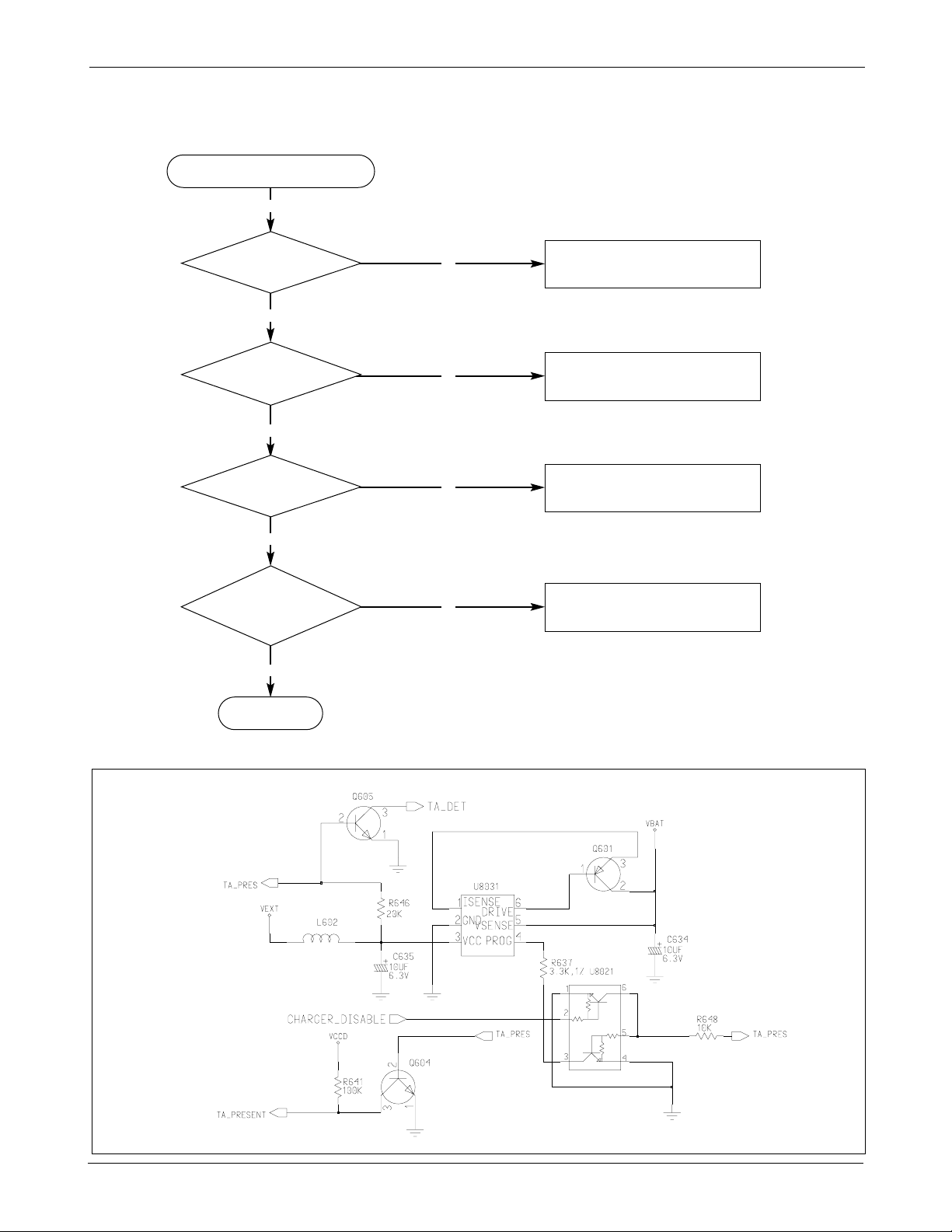
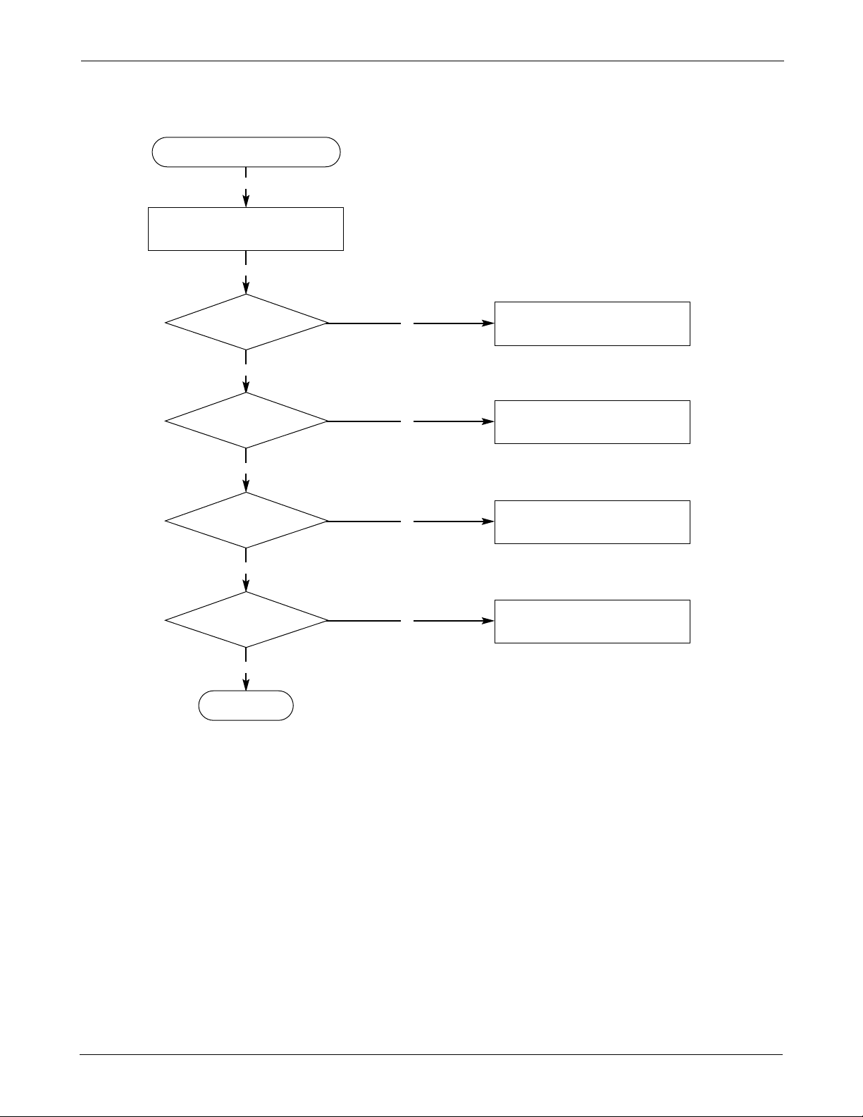
Abnormal charging part
Y
N
Y
Check
the pin 17, 18 of CN604-1
is around 5V
Replace TA
N
Y
Check the pin 2 of U8021
is “Low”
Check the U201
using Factory Test Program
N
Y
Check the
pin 5, 6 of U8021 is more
than 0.5V
Resolder R648, R651, R646
N
Y
Check the
Voltage of pin 5 of
U605 is between 3.2 V
and 4.2 V
Change U605
END
5-4 SGH-A400 Charging Part
SAMSUNG Proprietary-Contents may change without notice
5-5
SGH-A400 Flow Chart of Troubleshooting and Circuit Diagram
Mic-
C113
Mic+
Mic_Bias
22PF
1.1K
R103
330
C108
33UF
R104
C111
22PF
C116
C115
47NF
C112
47NF
1.1K
R107
33PF
5-5 SGH-A400 Microphone Part
Micro Phone does not work
Y
N
Y
check the connection
from MIC600
Change MIC600
N
Y
Audio loopback
is enabled by board test
program.
R104, R107 2.2 V
Resolder R104, R107, R103
END
SAMSUNG Proprietary-Contents may change without notice
5-6
SGH-A400 Flow Chart of Troubleshooting and Circuit Diagram
Speaker does not work
Y
Y
N
Y
Check the
connection from CN601
to LCD Module
Replace Flexible PCB
N
Y
Check the
voltage on the speaker
line lands on LCD
Module
Change the LCD Module
N
Y
Is Speaker working ?
Replace the Speaker
or resolder Speaker
END
5-6 SGH-A400 Speaker Part
Check the connection between CN601
and LCD Module connector
SAMSUNG Proprietary-Contents may change without notice
5-7
SGH-A400 Flow Chart of Troubleshooting and Circuit Diagram
5-7 SGH-A400 Key Data Input
Check initial operation
Y
Y
N
Y
Check the
pin 1, 3, 4, of CN602 is
“High”
Check the M46(U201)
N
Y
When one of the keys is
pushed, one of pin [5:12] of
CN602 is “High”
Replace the key PCB
END
Check the connection between
CN602 and Keypad.
SAMSUNG Proprietary-Contents may change without notice
5-8
SGH-A400 Flow Chart of Troubleshooting and Circuit Diagram
5-8 SGH-A400 Ring Indicator
Ring Indicator does not work
Y
Y
N
Y
Check the Q203 pin 2 is
“High”
Check M46(U201)
by Factory Test Program
N
Y
Check the Q203 pin 3 is
“Low”
Replace Q203
N
Y
CN602 pin 14 = “L” ?
Resolder CN602
N
Y
Key PCB is OK ?
Replace the key PCB
END
Check the connection between
CN602 and Keypad.
SAMSUNG Proprietary-Contents may change without notice
5-9
SGH-A400 Flow Chart of Troubleshooting and Circuit Diagram
5-9 SGH-A400 Back Light
Backlight does not work
Y
Y
N
Y
Backlight
“ON” mode in
the menu ?
Select backlight “ON” mode
N
Y
CN601 pin 3 = “High” ?
Check M46(U201)
using Factory Test Program
N
Y
Check the
connection from CN601
to LCD Module
Replace flexible PCB
N
Y
LCD backlight on ?
Replace LCD Module
END
Check the connection between
CN601 and LCD Module.
 Loading...