

SAMSUNG SGH-120 User Manual
AB68-00234A
PRINTED IN KOREA
INDOOR HOUSING
SHG-120
Installation Manual
Installationshandbuch
Manuel D’installation
Manual De Instalación
GB
D
F
E
C
J
K
2
GB
1
3.
Pole Mounted Adaptor (SADT-100PM): For installation on a cylindrical pole.
• The Wall Mounted Adaptor (SADT-100WM) is also used in conjunction with
the Pole Mounted Adaptor.
4. Corner Mounted Adaptor (SADT-110CM): For installation in the corner of a wall.
• The Wall Mounted Adaptor (SADT-100WM) is also used in conjunction with
the Pole Mounted Adaptor.
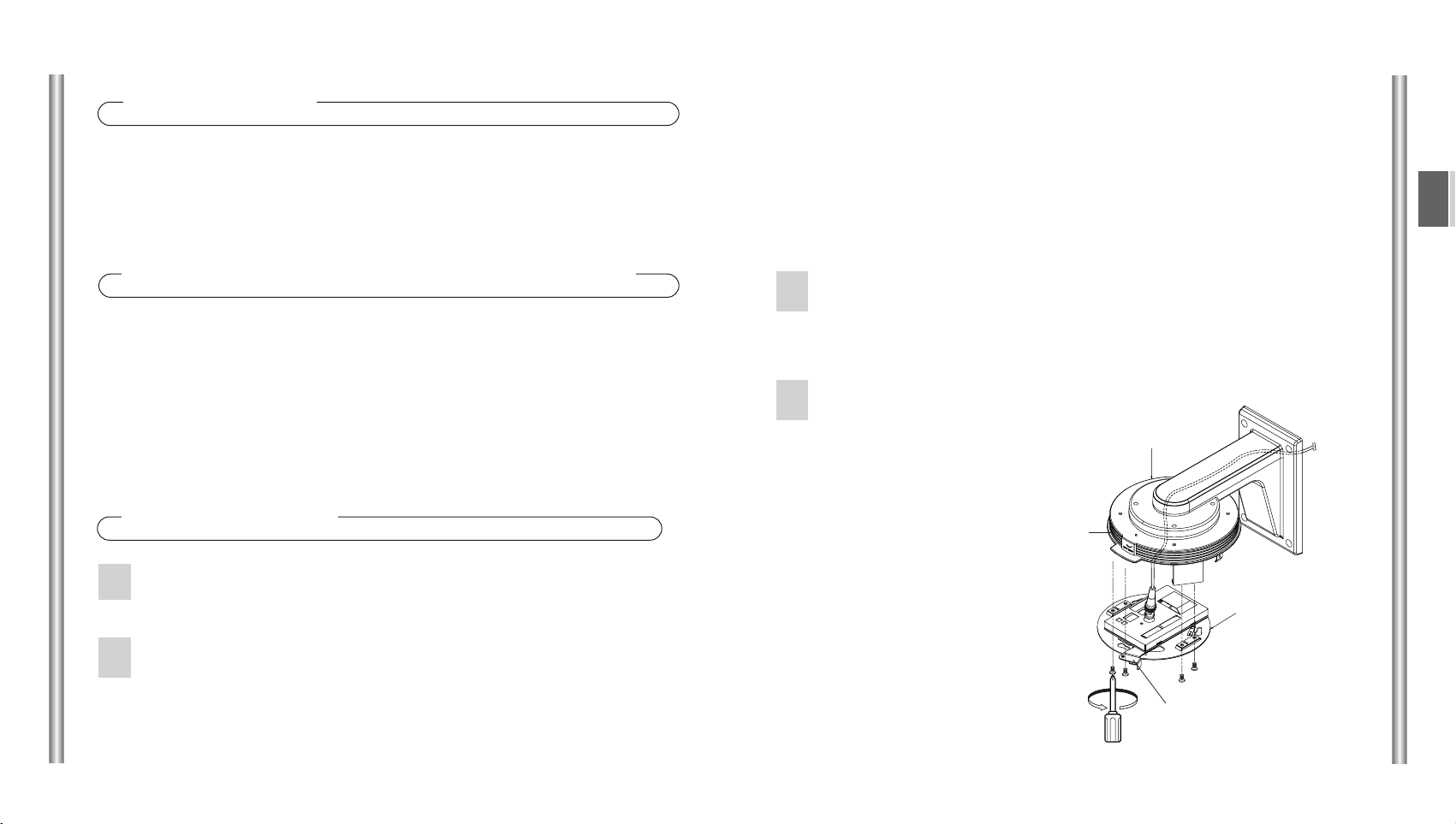
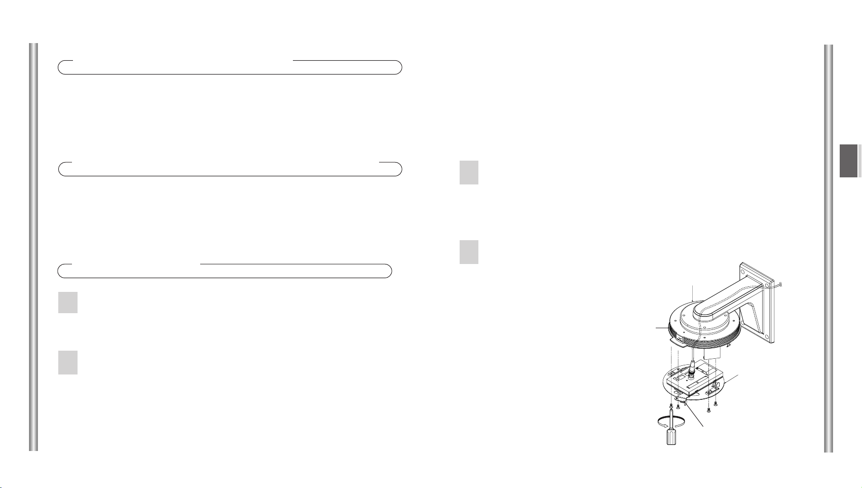
Connect the power cable, video-out cable and
communications cable to the camera adaptor . (For
details, refer to the Smartdome Camera User's Guide.)
After tidying up the cables, align
the lever of the camera
adaptor to the cover top
boss and fasten it to
the cover top using
four screws (M4
X8).
3
4
Installation
Select a location that will support four times the total
weight of the product to be installed.
Depending on the installation location, use the
appropriate adaptor.
1. Wall Mounted Adaptor (SADT-100WM): For direct installation on a wall.
2. Ceiling Mounted Adaptor (SADT-100CM): For installation on a ceiling.
1
2
Cover Top
Boss
Lever
Camera Adaptor
Summary
The Indoor Housing (SHG-120) is used for installing the
Smartdome Camera on an outside wall or ceiling.
Precautions Before Installation
•
Make sure that the proposed location can support the combined weights of the Corner
Mounted Adaptor, Wall Mounted Adaptor, Indoor Housing and Smartdome Camera
(about 8 kg).
•
This goods should only be installed by a qualified technician using approved materials
and wiring practices in accordance with national, state, and local electrical code.
2
1
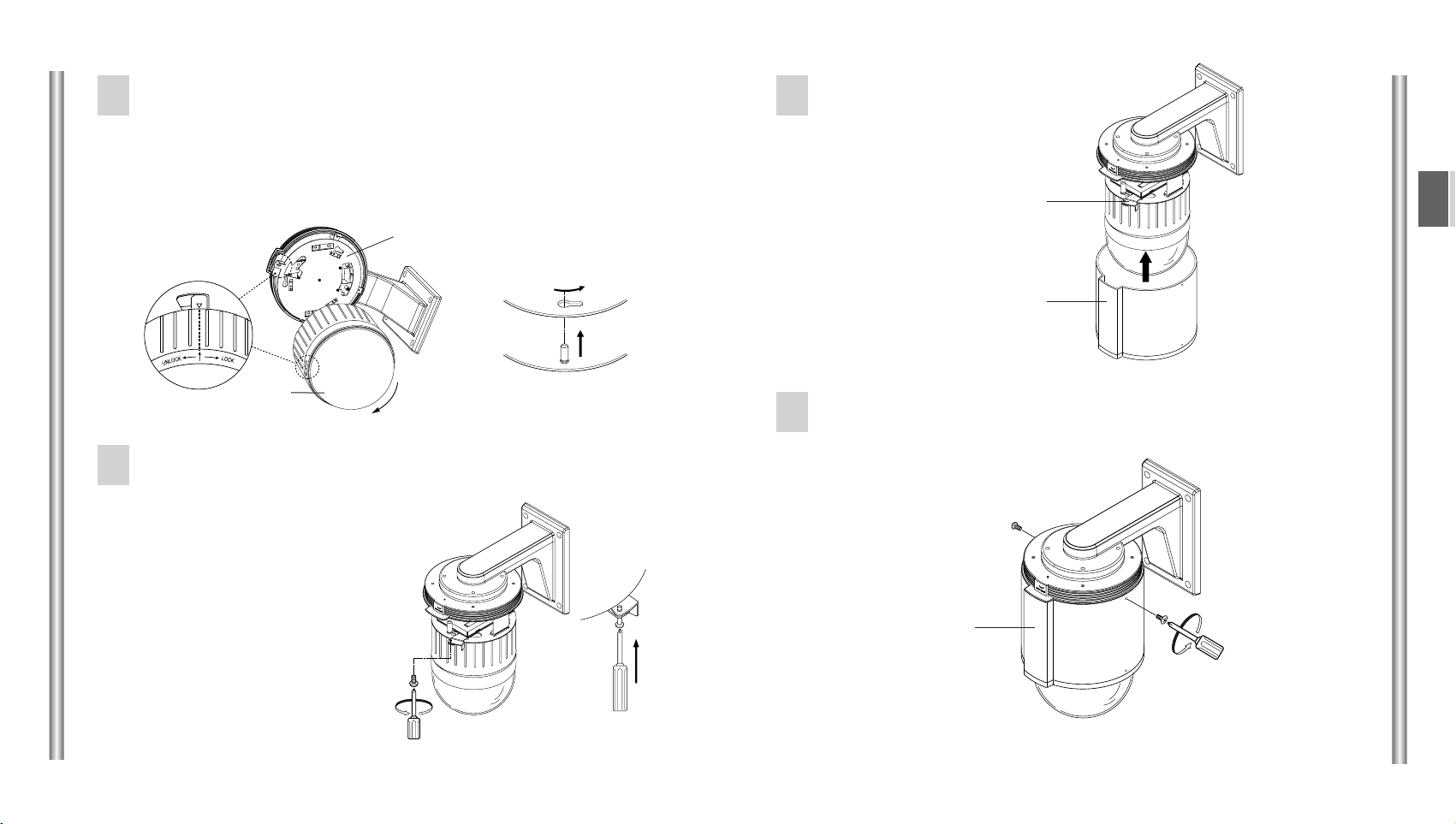
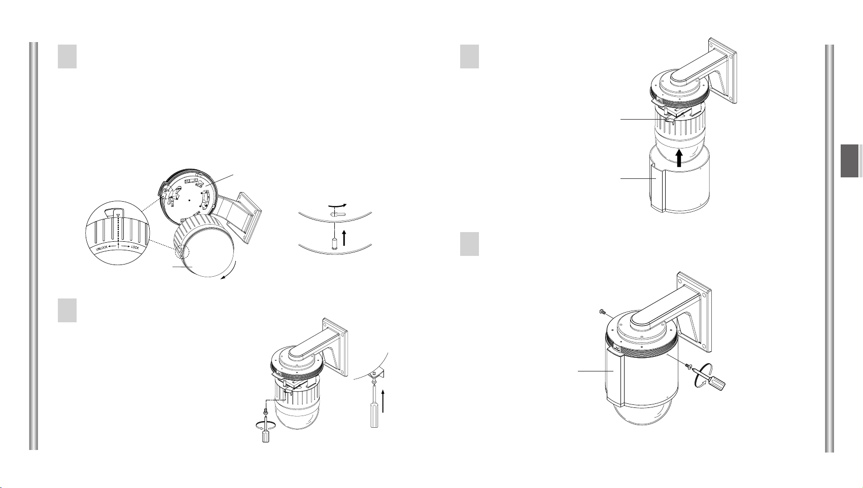
Fit two screws (BH M3 X L8) in the holes on the side of the
case body .
Secure the camera body to the camera adaptor using the
screw (BH M3 X L8) provided with the Smartdome Camera.
• To disengage the camera from the
camera adaptor, loosen the engaging
screw (BH M3 X L8), turn the camera
counterclockwise while the locking
lever is turned clockwise, and pull
the camera off .
4
GB
3
Align the arrow on the camera adaptor with the arrow on the
Smartdome Camera, insert the three bosses on the back of the
camera into the three camera adaptor holes, together with the
connectors, and turn the camera about 15 degrees clockwise.
(Listen for the click that confirms engagement and make sure
that the locking lever returns to its original position.)
5
6
15 degree
Camera Adaptor
Camera Adaptor
Camera
Align the boss of the
casing with the lever and
push the case body into
position.
7
Camera
Lever
Case Body Boss
Case Body
8
5
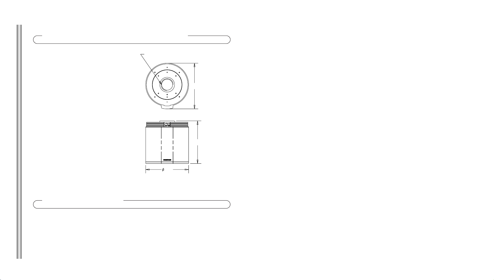
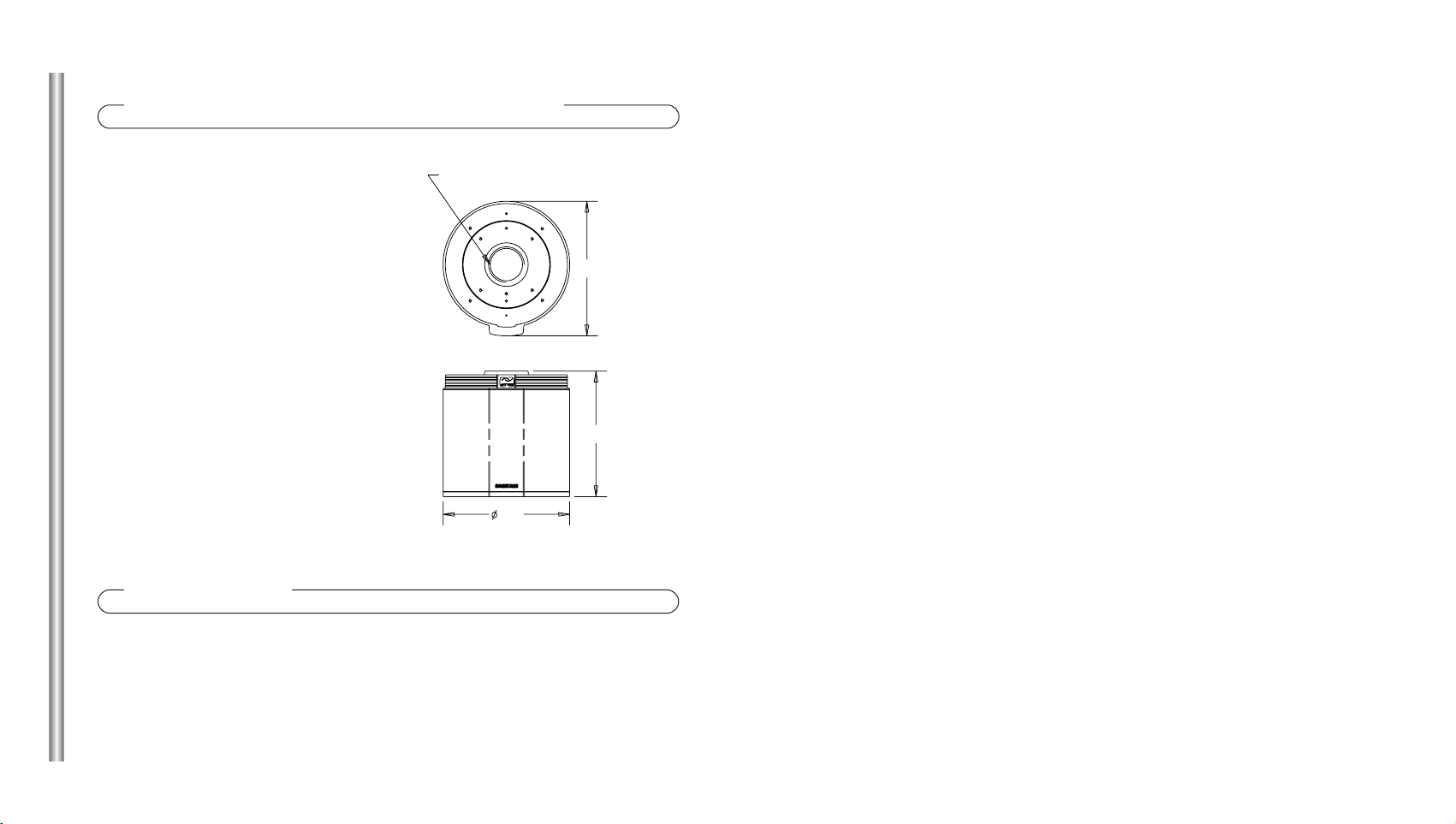
Product Specifications
External dimensions:
ø 174 ~ H173
Weight: 1.2Kg
Suitable T emperature range:
- 10°~ 50°C
Suitable Humidity range:
0 ~ 90%
173
174
185
Accessories
Screw(BH M3 X L8)
............................
2
1 1/2" NPT PIPE THREAD
2
D
1
3.
Pfostenadapter (SADT-100PM): Für die Installation an einem zylindrischen Pfosten.
• Der Wandadapter (SADT-100WM) kann auch zusammen mit dem
Pfostenadapter benutzt werden.
4. Eckadapter (SADT-110CM): Für die Installation in der Ecke einer Wand.
• Der Wandadapter (SADT-100WM) kann auch zusammen mit dem
Pfostenadapter benutzt werden.
Schließen Sie Netzanschlusskabel, Videoausgangskabel
und Datenübertragungskabel an den Kameraadapter an.
(Weitere Details finden Sie im Smartdome CameraBenutzerhandbuch.)
Nachdem Sie die Kabel verstaut haben, richten Sie den
Hebel des Kameraadapters zur
Nabe an der Gehäuseoberseite
aus und befestigen ihn mit
vier Schrauben (M4 x 8) an
der Gehäuseoberseite.
3
4
Installation
Wählen Sie eine Position, die das vierfache
Gesamtgewicht des zu installierenden Produktes tragen
kann.
Verwenden Sie je nach Installationsort den
entsprechenden Adapter .
1. Wandadapter (SADT-100WM): Für die direkte Installation an einer Wand.
2. Deckenadapter (SADT-100CM): Für die Installation an einer Decke.
1
2
Oberseite
Nabe
Hebel
Kameraadapter
Zusammenfassung
Das Innenraumgehäuse (SHG-120) dient zur Installation der
Smartdome Camera an einer Innenwand oder Decke.
Vorsichtsmassnahmen Vor Der Installation
•
Stellen Sie sicher, dass der geplante Ort das Gesamtgewicht von Eckadapter,
Wandadapter, Innenraumgehäuse and Smartdome Camera (ca. 8 kg) tragen kann.
2
1
Befestigen Sie zwei Schrauben (BH M3 xL8) in den
Löchern an der Seite des Gehäuserumpfes.
Befestigen Sie das Kameragehäuse mit der zur
Smartdome Camera mitgelieferten
Schraube (BH M3 x L8) am
Kameraadapter.
• Um die Kamera vom Kameraadapter
zu trennen, lösen Sie die Schraube
(BH M3 x L8). Drehen Sie die Kamera
gegen den Uhrzeigersinn und den
Verriegelungshebel im Uhrzeigersinn,
und ziehen Sie die Kamera ab.
4
D
3
Richten Sie den Pfeil auf dem Kameraadapter zum Pfeil auf der
Smartdome Camera aus, stecken Sie die drei Bolzen auf der
Rückseite der Kamera in die drei Kameraadapterlöcher
zusammmen mit den Steckverbindern ein und drehen Sie die
Kamera ungefähr 15 Grad im Uhrzeigersinn.
(Sie hören ein Klicken, das das Einrasten bestätigt. Achten Sie
darauf, dass der Verriegelungshebel in seine ursprüngliche
Position zurückspringt.)
5
6
15 Grad
Kameraadapter
Kameraadapter
Kamera
Richten Sie die Nabe des
Gehäuses zum Hebel aus
und drücken Sie den
Gehäuserumpf in
Position.
7
Kamera
Hebel
Gehäuserumpfnabe
Gehäuserumpf
8
5
Produktspezifikationen
Äußere Abmessungen:
ø 174 ~ H173
Gewicht: 1,2 kg
Geeigneter T emperaturbereich:
- 10°~ 50°C
Geeigneter Luftfeuchtigkeitsbereich:
0 ~ 90%
173
174
185
Zubehör
Schraube (BH M3 X L8)
....................
2
1 1/2” NPT-Rohrgewinde
 Loading...