

Page 1
8. Circuit operating theory
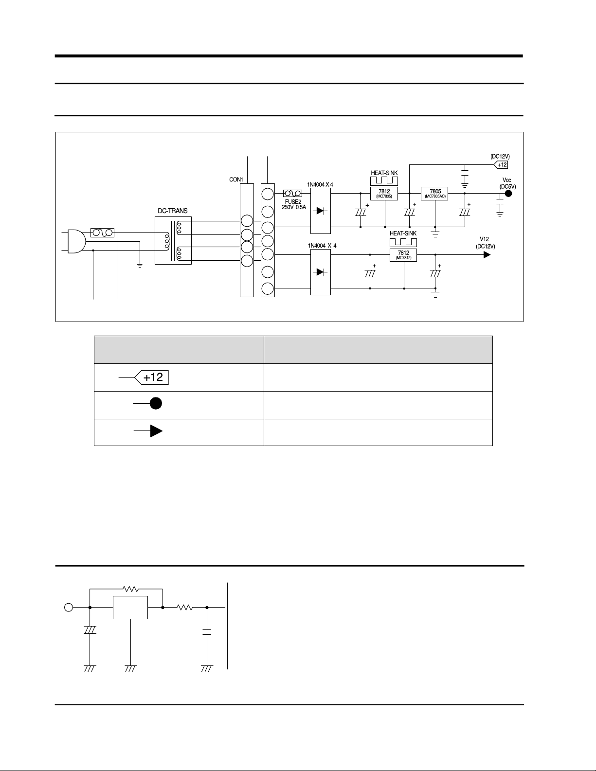
8-1 Power supply part
Voltage
(DC 12V)
Vcc (DC 5V)
V12 (DC 12V)
Secondary voltage output of DC trans is sourced 1~3 and 5~7 about 15V. On the ’a’ part, input is
rectified and regulated by MC 7812 and is about DC12V. This voltage is applied for relay running and
regulated again by 7805 to transformer. DC 5V is applied to display part after rectified and regulated by
MC7812.
Relay Operation
Power around MICOM & Sensor Detector
LED Display & S/W Detector
Circuit used
8-2 Resetpart
Reset part is intialize RAM of MICOM and others when
KA7533 RESET
+
29
power is on or power is interrupted for some time. It
will make whole program runs from the first status.
When power is supplied, reset voltage is ”low” status
for a few seconds and turn into ”High” status in the
normal operating.
16 Samsung Electronics
Page 2

8-3 Door S/W sensing part
DOOR
F
R
Door Conditions
CLOSE
OPEN
CLOSE
OPEN
Door S/W Contact
CLOSE
OPEN
CLOSE
OPEN
CON06
PIN NO
1
3
Micom Input Voltage
1) When the door is opened, the door S/W closed and MICOM input is ‘Low’.
Then the door-open is sensed.
2) When the door is closed, the door S/W is opened and MICOM input is ‘high’.
Then the door closed is sensed.
8-4 “V” motor, location sensing part ( Reed S/W)
“HIGH”
“LOW”
“HIGH”
“LOW”
1) “V” motor’s location sensing which is for G.A. fuzzy control is done by reed S/W.
2) There occure a “high” to “Low” and “Low” to “High” conversion period on con02 pin6 by the
motion of swing fan. “V” motor’s location is detected by it
Samsung Electronics 17
Page 3

8-5. Temp. sensing part
(Room Temp Sensor)
When Sensor is opened
MICOM input “HIGH”
1) Thermistor is used for sensing which has negative resistance coffiecient to the temperature.
2) MICOM input voltage, VF of sensor is ( Vcc: 5V, Rth : Sensor resistance )
3) Refer to conversion table for VF and RTH according to temperature.
VF= xVcc
RTH
RTH + R24
When sensor is cut off
MICOM input “LOW”
18 Samsung Electronics
Page 4

8-6 Comp and defrosting heater operating
As it is seen above block diagram, 220V line is connected to the commons of Comp relay, Ry78 and
defrosting heater relay, Ry77, Ry71. When those relays are off state Comp and defrosting heater are also
off. As Comp relay moves to on and AC 220V applied to Comp load it starts operating. On the other
hand defrost heater runs if defrost heater relay moves to on. There is no chance that both Comp and
defrost heater runs together so it’s useful for safety aspect.
COMP
ON
ON
ON
ON
RELAY
Defrost H
OFF
OFF
OFF
OFF
Load
Comp Operation
Comp off, Defrost-Heater Off
Defrost-Heater On
Comp Off, Defrost-Heater Off
Remark
Defrost-Heater Power Off
Comp Power Off
Samsung Electronics 19
 Loading...