

SAMSUNG SG626ECSWQDOR Service Manual
REFRIGERATOR
Model : SR-L676EV
SR-L678EV
SR-L626EV
SR-L628EV
GREEN
REFRIGERATOR CONTENTS
1. Precautions
2. Product Specifications
3. Electrical Part Specifications & Standard
4. Circuit Diagram
5. Functions & Operating Instruction
6. Circuit Descriptions
7. Troubleshooting
8. Parts List
9. Disassembly & Assembly
SR-L676EV
SR-L678EV
SR-L626EV
SR-L628EV
10. PCB Circuit Diagram
11. PCB Parts List
12. Specifications of Main Components

ELECTRONICS
© Samsung Electronics Co., Ltd
August, 1998
Printed in Korea
Code No. DA68-60281C
1. Precautions
Warning : Please abide by the following
precautions in order to conduct the
maintenance procedures in a
safety fashion.
1-1. Caution when doing repairs
• Do work after extinguishing fire in the
surrounding area. When freon-gas makes
contact with the heater, hazardous gas will
leak out.
• Don’t use welding machines in confined
indoors.
• In the case of gas leakage, always open the
windows.
• When cutting the SUCTION, DISCHARGE
pipe of the compressor, always take
caution of the inner pressure of the
remaining gas.
1-2. Take out the power plug
• Always take out the power plug from the
outlet when doing repairs.
1-8. Check for disconnection
• After completing the assembly, always
measure the disconnection resistance level,
and turn on the power after checking it is
above 1MΩ.
1-9. Earth
• Check the status of earthing and repair the
incomplete ones.
1-10. Be careful of children
• There is always the possibility of danger
involved so make sure children can’t
come nearby when doing repairs.
Cleaning : After completing repairs, clean the
surrounding area and the
refrigerator and tell the consumer
about the repairs being made.
Refers to prohibition.
1-3. Be careful of electric shocks
• When inspecting the circuit, don’t touch
the battery charger and be careful of
electric shocks.
1-4. Use proper components
• Always use the component labeled in the
service component chart when replacing
components for repairs.
1-5. Use proper tools
• Always use proper tools for repairs. If
worn out tools are used, it would cause
defects in tuning and electrical contact,
leading to accidents.
1-6.
When doing repairs, inspect the
CORD
wire and make sure they are replaced.
or whether there is fire in the lead
POWER
1-7. Cutting of LEAD-WIRE
• For connecting the lead-wire that has been
cut off, use soldering or connector and
always disconnect the vinyl tapes.
Refers to prohibition of dismantling.
Refers to prohibition of contact.
Refers to guidelines which have to be
followed.
Refers to detaching the power plug
from the outlet.
Refers to earth connection for
preventing electric shocks.
Refers to possibility of death or
serious injury of a person.
Warning
Refers to possibility of injury of a
person or damage to property.
Caution
Samsung Electronics 1
Reference
Reference1
Reference2
NO
C
NC
Coil bisection
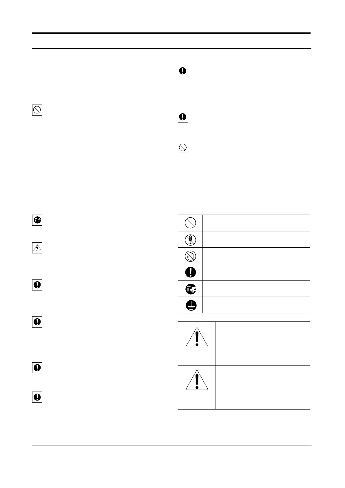
The connection of DOOR-CABI
BLK
1
2
BRN
3
MAIN
PCB
RED
4
ORG
5
YEL
6
PNK
7
BLU
8
PUR
9 9 9
GRY
10
WHT
11
S/BLU
CON7
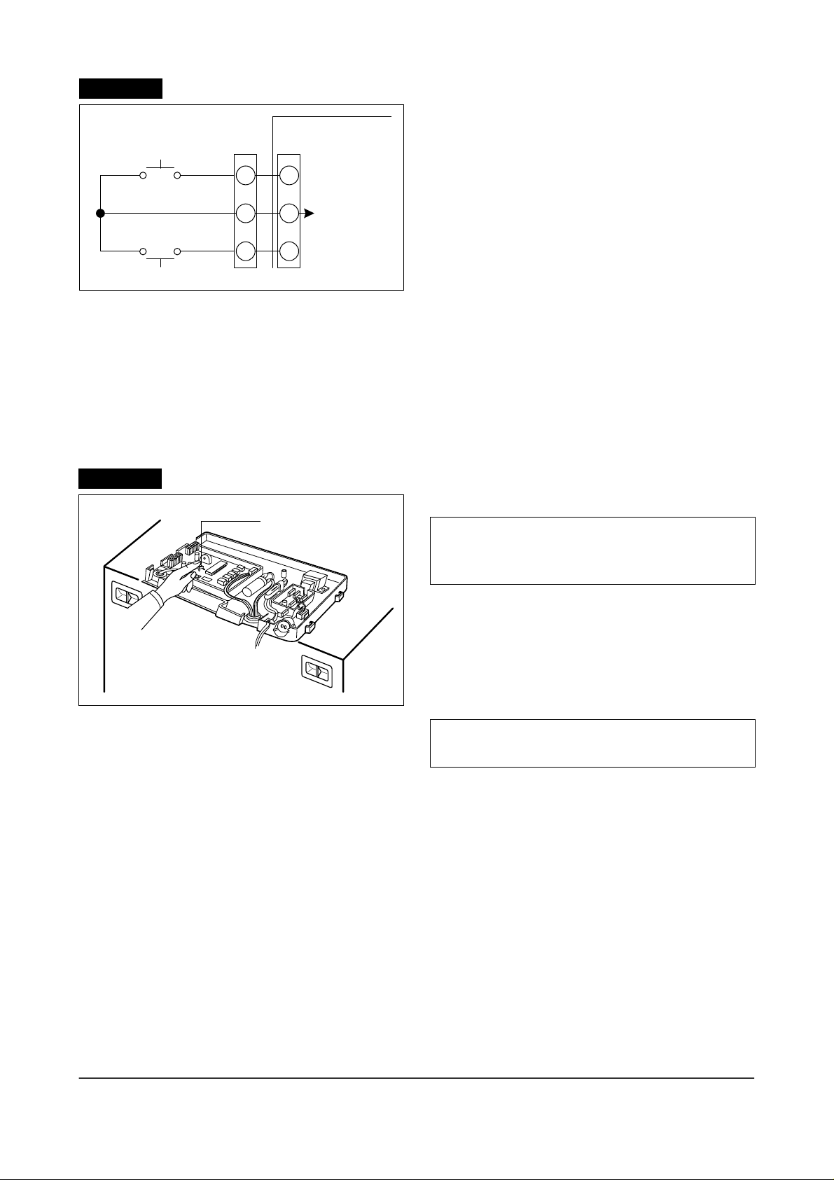
Inspection of Relay
Coil bisection
Measure after
separation
(Relay Movement)
CON9
CON10
MAIN PCB
CON8
10
11
12
1
1
2
2
3
3
4
4
5
5
6
6
7
7
8
8
10
11
12
10
11
1
2
3
4
5
6
7
8
9
BLK
BRN
RED
ORG
YEL
PNK
BLU
PUR
GRY
WHT
S/BLU
PANEL
PCB
* First separate the housing connected to the
main PCB CON C8, 09, 10 and measure the
following items.
1. M e a s u re the coil bisection of the relay and
check whether it works.
2. Measure the apex bisection for open circuit.
Apex category The voltage of
coil bisection
DC 12V(Operation)
Apex 3
DC 05V(Standstill)
Apex 2
DC 12V(Operation)
DC 0V(Standstill)
Judging the apex
bisection
C:NO SHORT
C:NC OPEN
C:NO OPEN
C:NC SHORT
SHORT
OPEN
Note) C →Common, NO → Normal open, NC → Normal close
3. When it operates as above, it is normal and
when it does not operate, report the
corresponding relay.
36 Samsung Electronics
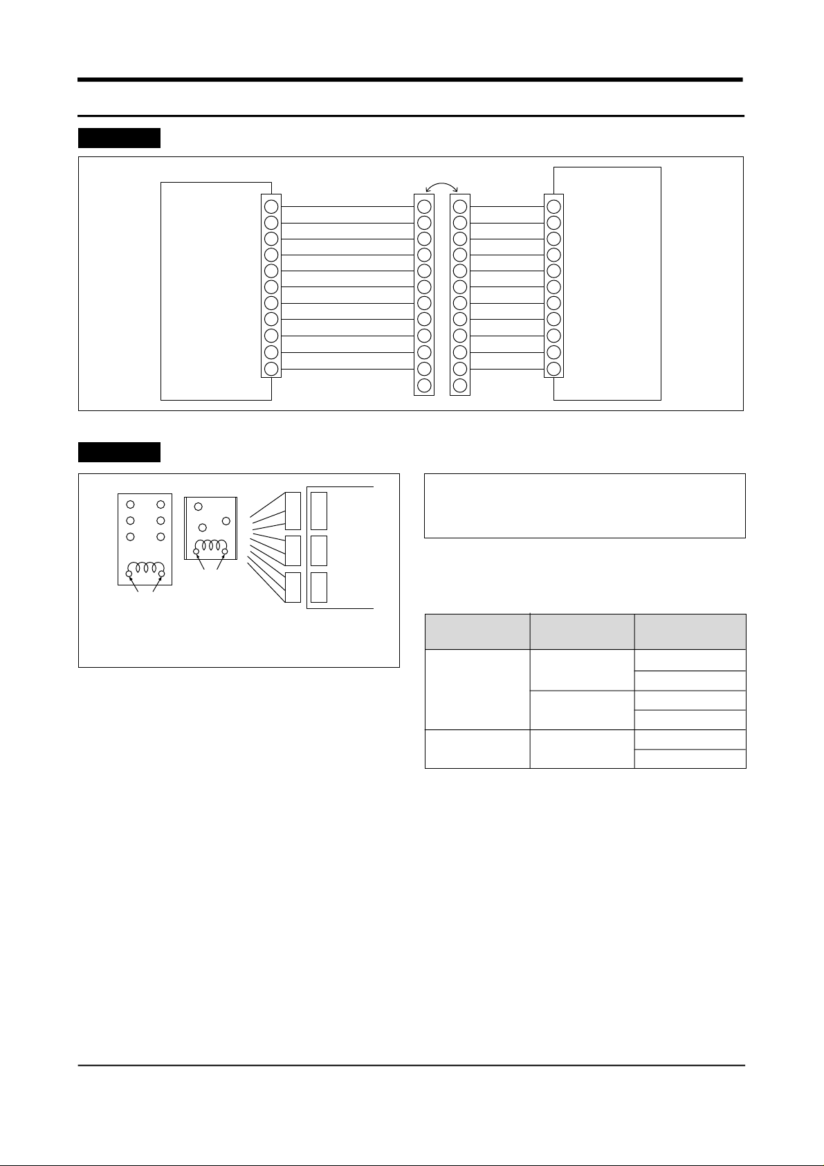
Reference3
Short
Check for malfunctioning of the subordinate
Measure after separation
* Cut off the power code, separate the housing
from the main PCB CON 08, 09, 10 and
measure the following.
CON9
R-Defrost heater
SWINT MOTOR
R-C/FAN
RED
Note) The compressor is impossible to measure resistance by the
running and starting condenser.
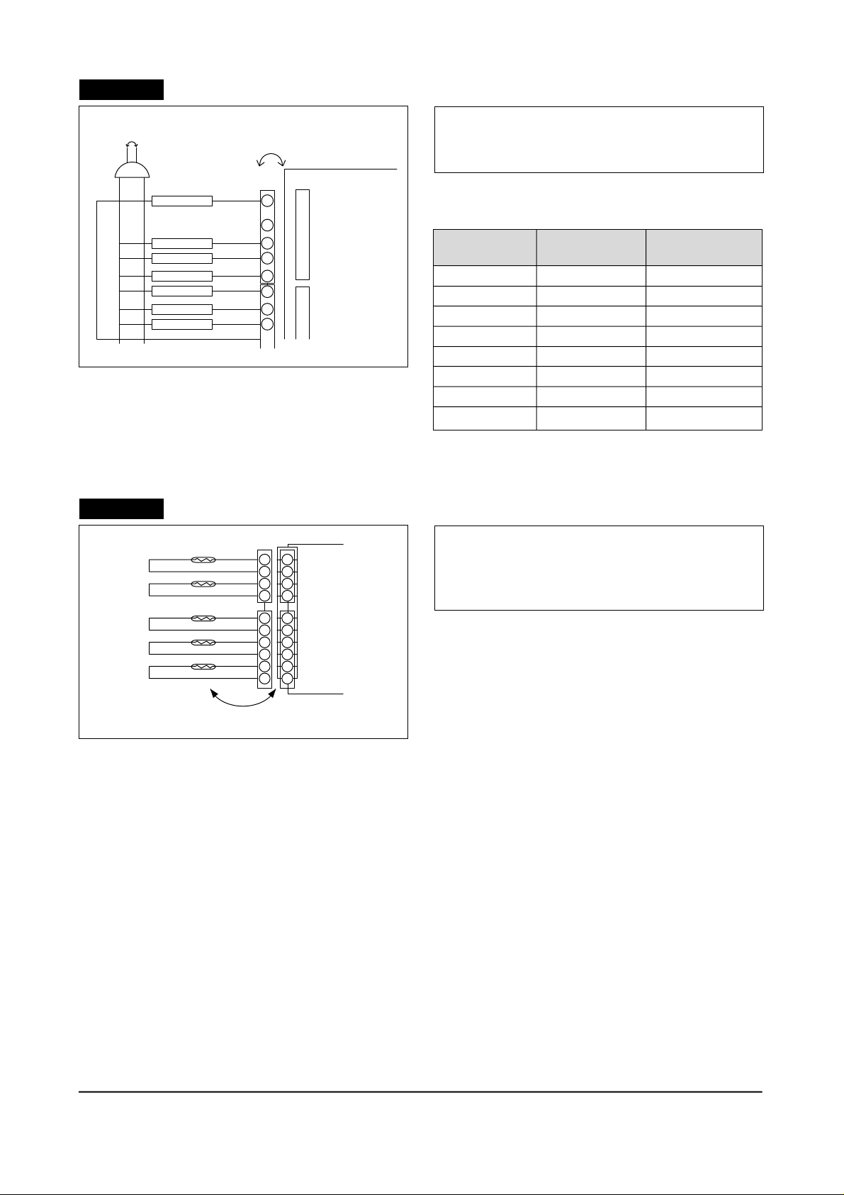
Reference4
R-Lamp
F-Lamp
F-C/FAN
COMP.
Inspection of the sensor
R2 ROOM
R1 ROOM
F - ROOM
R / DEF - SONSOR
F / DEF - SONSOR
RED
8
7
5
3
1
CON10
9
7
5
4
3
2
1
CON3
1
2
3
4
5
6
Measure after separation
CON2
4
3
2
1
MAIN PCB
1
2
3
CON3
4
5
6
CON9
CON10
1. Measure resistance between the terminals and
check for malfunctioning of L/W.
Subordinate
R Defrost heater
F Defrost heater
Comp
Swing motor
R-Circulation fan
F-Circulation fan
R-Lamp
F-Lamp
M e a s u r e m e n t
t e r m i n a l
CON9 ⑨& CON10
CON8 ③& CON10
CON8 ⑤& CON10
CON8 ①& CON9
CON8 ①& CON9
CON8 ①& CON10
CON8 ①& CON9
CON8 ①& CON10
Evaluation of mea-
surement result
③
0Ω or ∞Ω(defect)
③
Impossible to measure 0Ω indicator
⑤
0Ω or ∞Ω(defect)
⑤
③
⑦
①
⑨
* Separate the housing connected to main PCB
CON2 and CON3.
* Resistance value lowers while temperature
rises, because it is a NTC type sensor.
1. R1 sensor measures resistance of CON2
between ①~②.
2. R2 sensor measures resistance of CON2
between ③~④.
3. Freezer sensor measures resistance of CON3
between ①~②.
4. R-defrost sensor measures resistance of CON3 between ③~④.
5. F-defrost sensor measures resistance CON3 between ⑤~⑥.
6. The measurement value above is calculated by comparing th e present temperature of the sensor and
the temperecture table in specification found in the manual.
Samsung Electronics 37
Reference5
Checking the Door S/W
(Refrigerator Bulb)
1. Open the door and check if the freezer bulb
F - Door S/W
1
1
22
CON6
MAIN
PCB
DC 12V
turns on.
2. Press the Door S/W and check if the freezer
bulb turns off.
3. Close the door of freezer and repeat 1 and 2 for
refrigerator.
3
R - Door S/W
3
4. If there is a problem, check bulb and door S/W.
5. Check wire connection.
(Micom signal)
1. Check if CON6 ① and ③is 0V DC after closing the F·R doors.
2. Check if CON6 ①is 12V DC when opening F door.
2. Check if CON6 ③is 12V DC when opening R door.
3. If there is problem, check door S/W and wire connection.
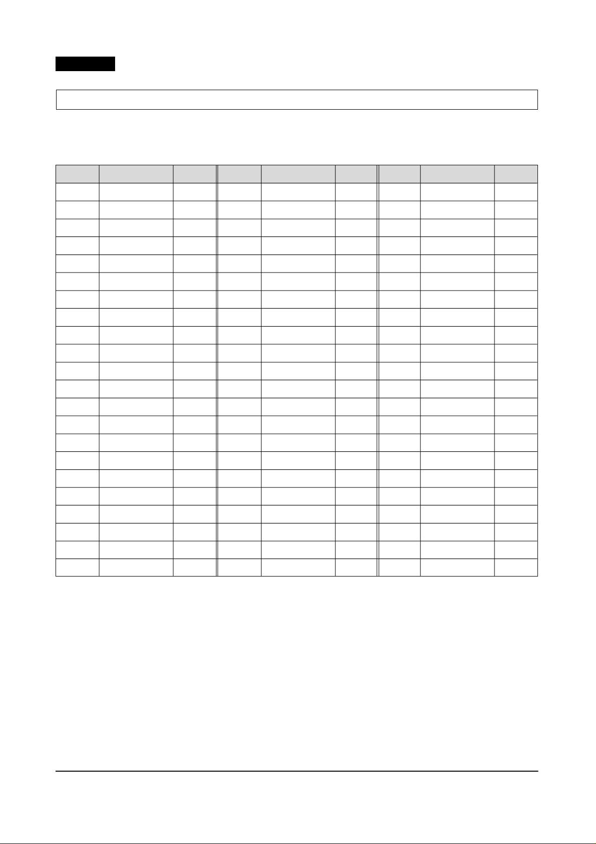
Reference6
Forced starting & forced defrosting
TEST S/W
(Forced starting)
* This function is used to turn on the comp and
fan immediately regardless of the temperature
of freezer.
1. Press the button on the PCB after removing the
main PCB cover from the upper part of
refrigerator.
2.
Buzzer will sound to indicate the forced starting.
(Forced defrosting)
* This function is used to turn on the defrosting
regardless of defrost time.
1. Press the button twice during forced starting.
Then, defrosting is performed.
2. If the button is press 3 times during Rdefrosting, F-defrosting is also performed at
the same time.
3. If the button is pressed 4 times during R-f
defrosting, test mode is released.
38 Samsung Electronics
Reference7
Sensor Short : Micom 0V.
Sensor Open : Micom 5V.
Sensor resistance and voltage conversion table for temperature
(Sensor pressure voltage 10KΩ – Voltage converted by the F-reference)
* Voltage conversion table depends on H/W structure of MICOM port input voltage.
✽ Sensor partial pressure resistance 10KΩ
TEMP.
– 35
– 34
– 33
– 32
– 31
– 30
– 29
– 28
– 27
– 26
– 25
– 24
– 23
– 22
– 21
– 20
Resistance KΩ ± 1%
68.648
65.011
61.595
58.384
55.366
52.526
49.854
47.337
44.967
42.733
40.626
38.640
36.765
34.995
33.323
31.743
Voltage(V)
4.364
4.333
4.301
4.268
4.235
4.2
4.164
4.127
4.09
4.051
4.012
3.972
3.93
3.888
3.845
3.802
TEMP.
– 13
– 12
– 11
– 10
– 9
– 8
– 7
– 6
– 5
– 4
– 3
– 2
– 1
0
1
2
Resistance KΩ ± 1%
22.832
21.814
20.848
19.932
19.062
18.237
17.453
16.709
16.001
15.328
14.688
14.080
14.501
12.949
12.424
11.924
Voltage(V)
3.477
3.428
3.379
3.329
3.279
3.229
3.178
3.127
3.076
3.025
2.974
2.923
2.872
2.821
2.77
2.719
TEMP.
9
10
11
12
13
14
15
16
17
18
19
20
21
22
23
24
Resistance KΩ ± 1%
9.016
8.673
8.345
8.032
7.732
7.446
7.172
6.910
6.659
6.420
6.190
5.970
5.759
5.557
5.363
5.178
Voltage(V)
2.37
2.322
2.274
2.227
2.18
2.134
2.088
2.043
1.998
1.954
1.911
1.869
1.786
1.786
1.745
1.705
– 19
– 18
– 17
– 16
– 15
– 14
30.250
28.838
27.502
26.237
25.040
23.906
3.757
3.712
3.666
3.62
3.573
3.525
3
4
5
6
7
8
11.447
10.993
10.559
10.146
9.752
9.375
2.668
2.618
2.567
2.518
2.468
2.419
25
26
27
28
29
30
5.000
4.829
4.665
4.508
4.357
4.212
1.666
1.628
1.59
1.553
1.517
1.481
Samsung Electronics 39
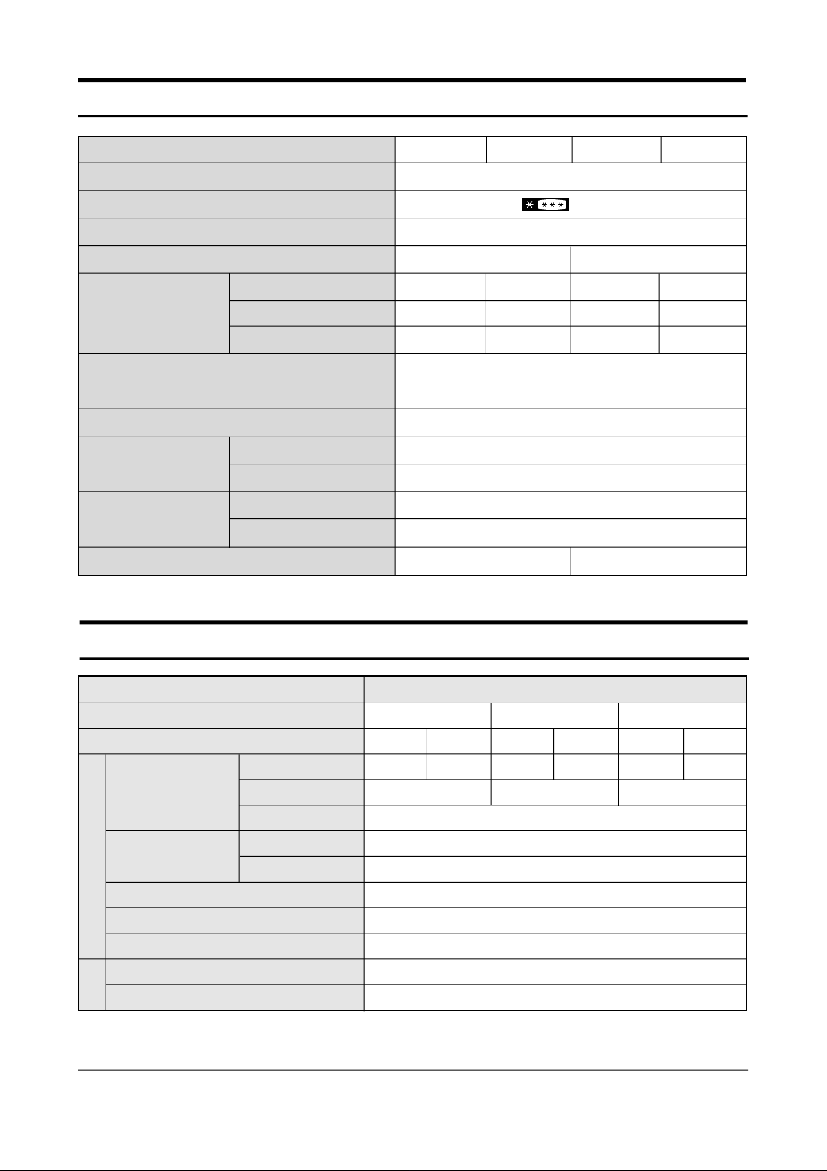
2. Product Specifications
Freezer performance
Temperature control
Net Capacity
l/(ft3)
Foam
Liner
Model
Type
Water dispenser
Net dimension
(WXDXH)
Refrigerant
Cabinet insulation
Door insulation
Freezer
Refrigerator
Total
Cabinet
Door
SR-L628EV SR-L678EV SR-L626EV SR-676EV
(LMF(Freezer/Refrigerator) 2 Door)
(4-STAR)
Electronic control
Yes
171(6.04) 192(6.78)
345(12.18) 376(13.28)
516(18.22) 568(20.06)
820X715X1790 (mm) (SR-L626(8)EV)
820X765X1790 (mm) (SR-L676(8)EV)
HFC-134a(160gr)
CYCLO-PENTANE
CYCLO-PENTANE
171(6.04) 192(6.78)
351(12.39) 382(13.49)
522(18.43) 574(20.27)
A.B.S
A.B.S
No
Net weight
114Kg 113Kg
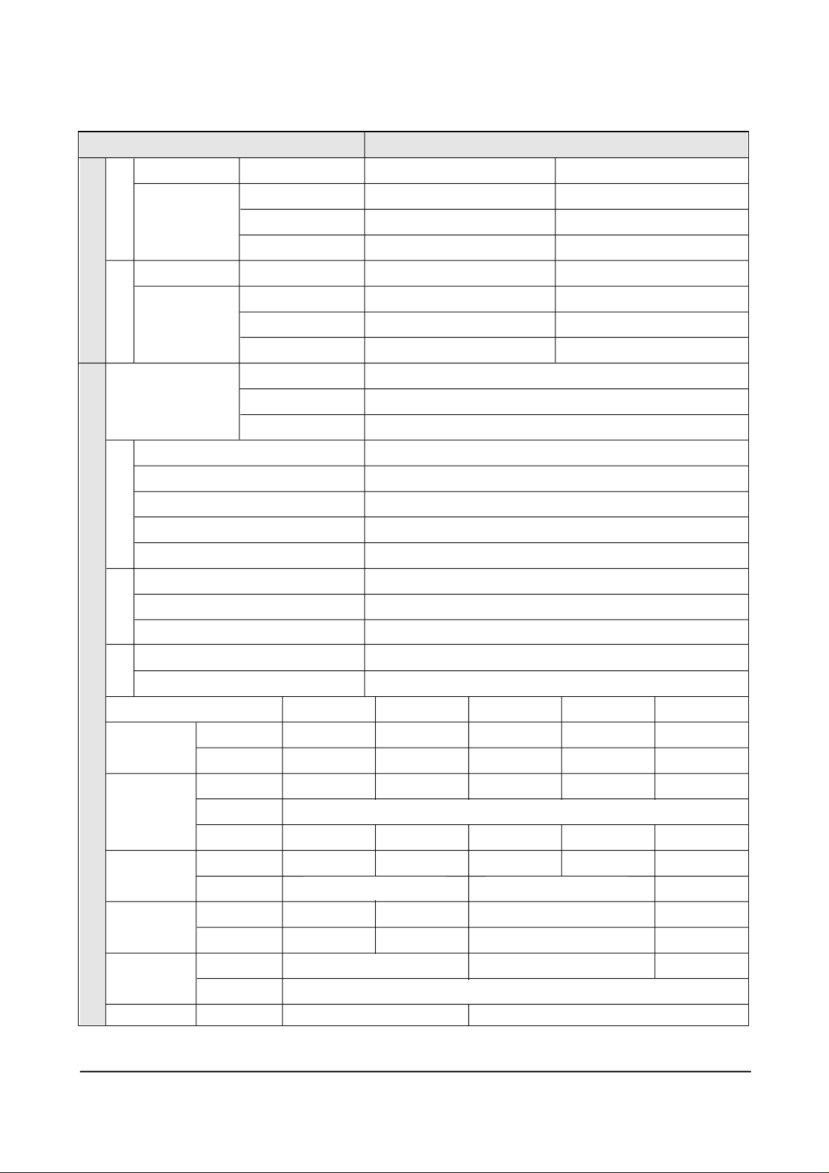
3. Electrical part specifications & standard
ITEM
Model
Input Source
Compressor
Evaporator
Condenser
Refrigeration Cycle
Dryer
Capillary tube
Model
Starting type
Oil charge
Freezer
Refrigerator
SR-L626/628EV SR-L626(8/676(8)EV SR-L676/678EV
220V 240V
SK182H-L2U SK182Q-L2U
RSCR
Forced & Natural Convection Type
115V 127V
SK182E-L2W SK182P-L2
Freon α-15(ESTER)
Molecular Sieve XH-9
ID0.85XL2500 3.79kg/cm
STANDARD
220V 240V
W
SK190H-L2U SK190Q-L2U
CSR RSCR
Split Fin Type
Split Fin Type
2
Earth screw
Door switch
2 Samsung Electronics
BSBN(Brass screw)
250V/0.5A
ITEM STANDARD
FreezerRefrigerator
F-Sensor
Temperature
R-Sensor
Defrosting
Sensor
Type
Type
Defrost cycle
Freezer-Sensor
Refrigerator-Sensor
FRE EVAP-Sensor
REF EVAP-Sensor
Room TEMP-Sensor
Mode
High
Mid
Low
Mode
High
Mid
Low
Rest time
First cycle
ON(˚C)
–20˚C
–16.5˚C
–14˚C
ON(˚C)
–0.5˚C
3.5˚C
6.5˚C
OFF(˚C)
–22˚C
–18.5˚C
–16˚C
OFF(˚C)
–1.5˚C
2.5˚C
5.5˚C
Freezer:6 – 16hr/Refrigerator:12 – 32hr
10min±2min
4hr±10min
502AT
502AT
502AT
502AT
502AT
Heater
Fuse
Electrical parts
VOLTAGE 115V 127V
C O N D E N S E R
O V E R - L O A D
P R O T E C T O R
S TA RT I N G R E L A Y
M O T O R - FA N
L A M P
M O T O R - G E A R E D
FRE Defrost-Heater
REF Defrost-Heater
Lamp-Heater
FRE Defrost-Fuse
REF Defrost-Fuse
STARTING
RUNNING
MODEL
1 2 5 VA C / 1 2 5
2 5 0 VA C / 1 2
4 T M 4 4 5 S H B Y Y- 5 3
ON TEMP .
OFF TEMP .
MODEL
P T H A S - T 1 0 0 M 2 0 0 B
RESIST ANCE
FRE. REF .
C I R C U I T- M O T O R
I S 3 2 0 8 T M D A - 4
I S 3 2 0 8 - S C F 6 A
FRE.
REF.
REF.
200W (115V, 127V, 220V, 240V)
130W (115V, 127V, 220V, 240V)
2W (115V, 127V, 220V, 240V)
250V 10A 72 ± 4˚C
250V 10A 72 ± 4˚C
2 2 0 V
1 2 5 VA C / 1 2 5
µ F
2 5 0 VA C / 1 2
µ F
4 T M 4 4 4 N H B Y Y- 5 3
µ F
µ F
3 5 0 VA C / 5
4 T M 3 0 8 P H B Y Y- 5 3
( 6 2 6 / 6 2 8 E V )
2 2 0 V
µ F
3 5 0 VA C / 5
4 T M 3 1 4 R H B Y Y- 5 3
( 6 7 6 / 6 7 8 E V )
µ F
3 5 0 VA C / 5
4 T M 2 3 2 S H B Y Y- 5 3
6 9 0˚ C
1 3 5˚C
1 0W ± 2 0 %
1 2 0˚ C
P T H A S - T 1 0 0 M 2 0 0 B
I S 3 2 0 8 T M D A - 8
I S 3 2 0 8 - S C O 6 A
1 2 5˚ C
P T H A S - T 2 2 0 M 3 5 0 D
2 2W ± 2 0 % 3 3W ± 2 0 %
I S 3 2 0 8 T M D A - 2 A
I S 3 2 0 8 - S C F 7 A
1 3 0˚ C
P T H A S - T 2 2 0 M 3 5 0 D
1 3 5˚ C
P T H A S - T 3 3 0 M 3 8 5 D
I S 3 2 0 8 T M D A - 6
I S 3 2 0 8 - S C L 5 A
1 1 0 V ~ 1 3 0 V / 1 5 W 2 2 0 V / 1 5 W 2 4 0 V / 1 5 W
OSRAM DEULX S/E IIW
M 2 B C 1 8 A R 0 2 M 2 L C 1 8 A R 0 2
2 4 0 V
µ F
Samsung Electronics 3
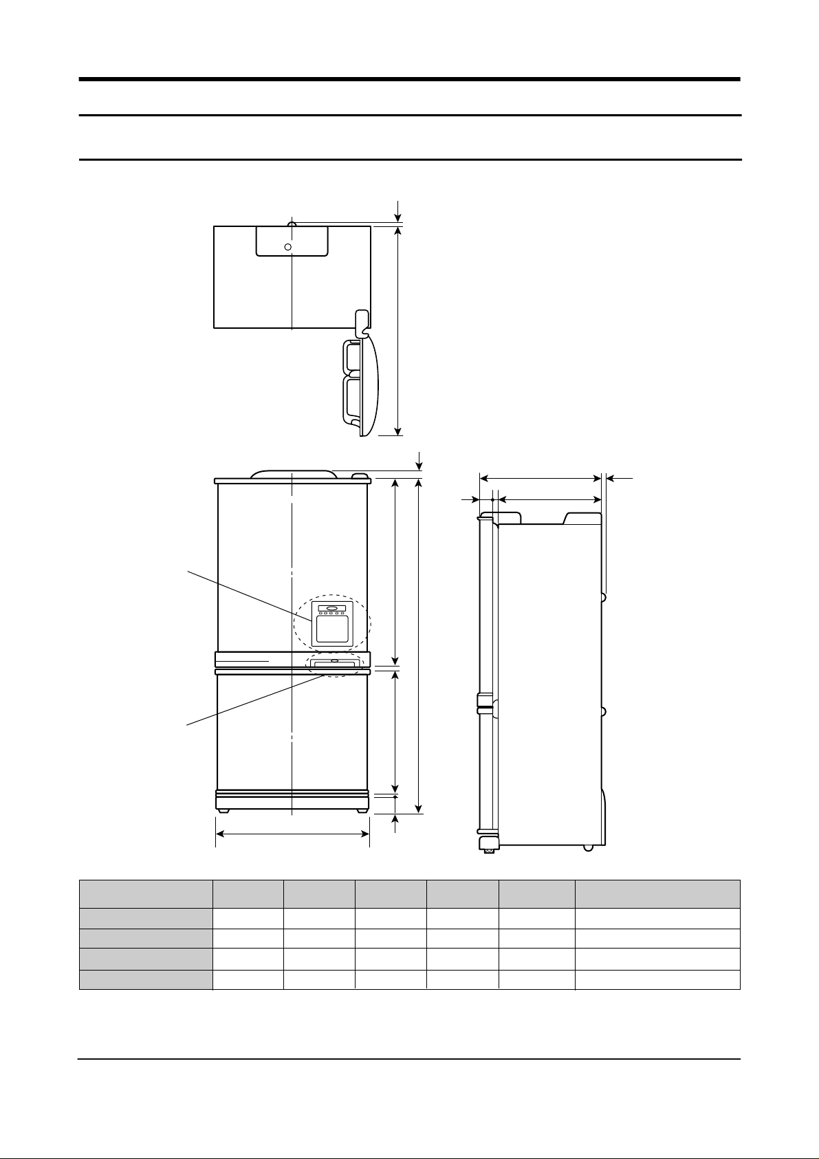
5. Function & Operating Instruction
• 5-1 Product Dimension
10
C
"X"
"Y"
820
B
673.5
10
64
11
D
E
40
77
A
8
10
MODEL
SRG-L678EV
SRG-L676EV
SR-L628EV
SR-L626EV
6 Samsung Electronics
A
1750.0
1750.0
1750.0
1750.0
B
994.5
994.5
994.5
994.5
C
1509.7
1509.7
1459.7
1459.7
D
755
755
715
715
E
667
667
627
627
Remarks
"X"
"Y"
"X"
"Y"
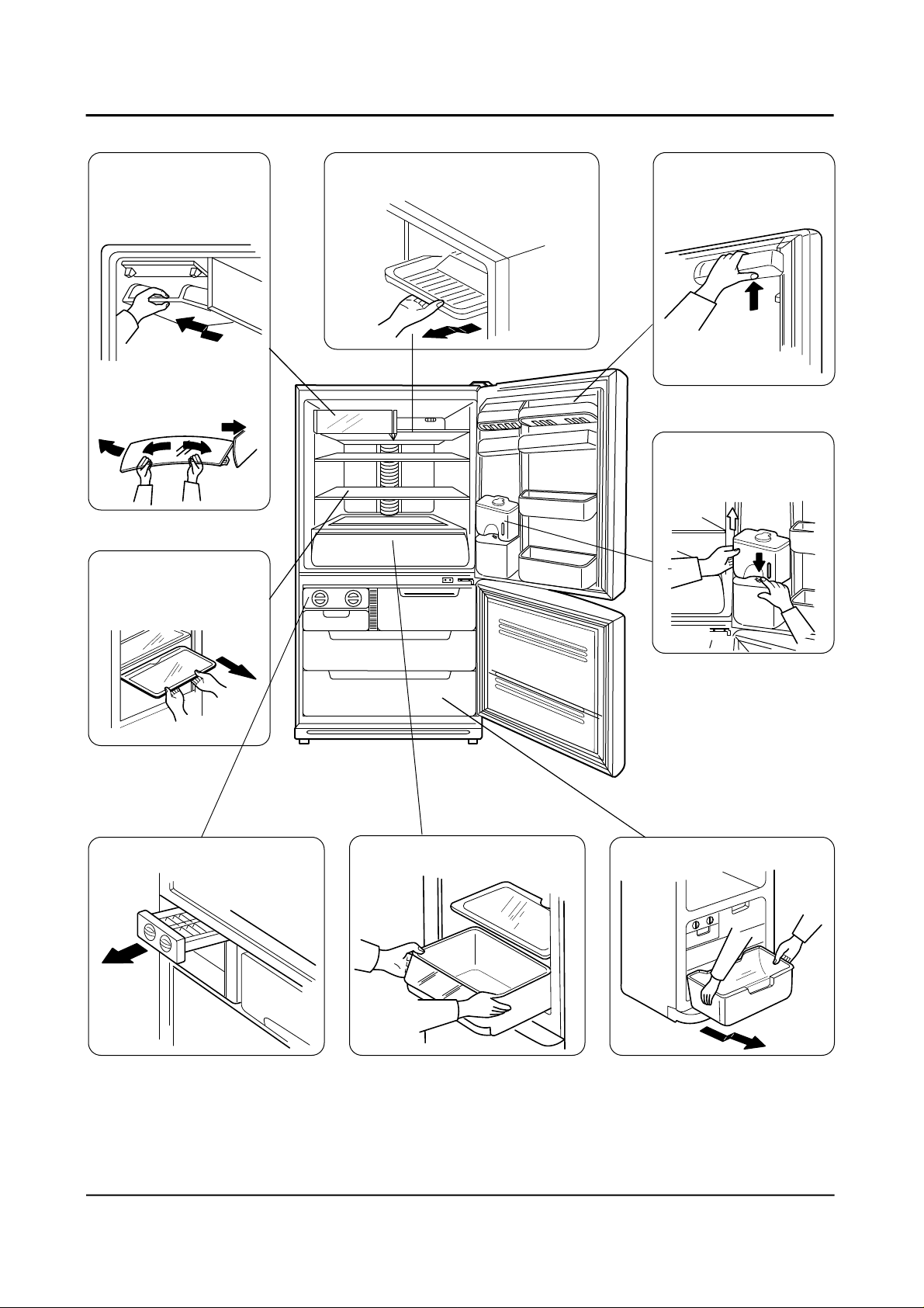
5-2 Part Name & Disassembly
• Chilled Compartment
disassembly
1. Pull it out by following
the arrow.
2. Bend the cover and
take it out.
②
①
• Tray disassembly
Pull it out by following
the arrow.
• Top tray disassembly
Pull it forward.
•
•
•
•
•
Take out food stuffs and
pull it out by following
the arrow.
•
Take out the water
bottle with the bottom
latch pressed.
•
•
• Ice compartment • Vegetable compartment
• Freezing compartment
Samsung Electronics 7
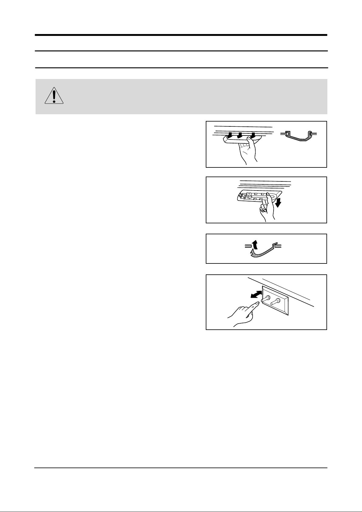
9. Disassembly & Assembly
1. Replacement of refrigerator lamp
Warning
Always take out the power plug when replacing the refrigerator lamp. There is the danger of
electric shock.
1. Remove the cover with the back latch pressed.
2. Pull out the lamp.
3. After replacing the lamp, assemble the front latch of
cover and then connect the back latch.
4. Plug in and check if power is cut off or not by pressing
the R-door switch.
52 Samsung Electronics
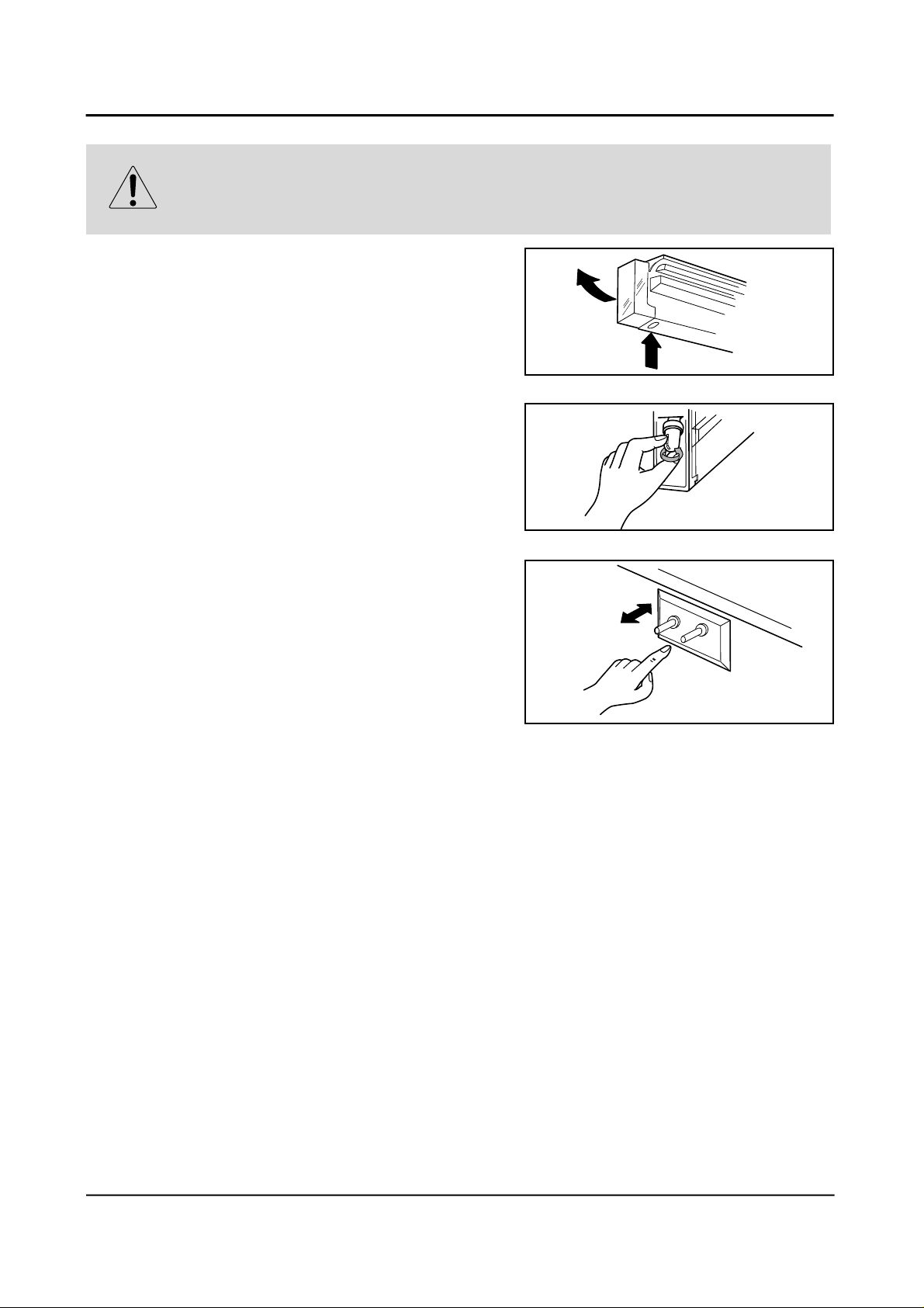
2. Replacement of freezer lamp
Warning
Always take out the power plug when replacing the refrigerator lamp. There is the danger of
electric shock.
1. Remove the cover by pressing the bottom latch.
2. Replace the lamp by turning it counter-clock wise.
3. Reassemble the cover in the reverse order of
disassembly and plug in and the check if power is cut
off by pressing the door switch.
Samsung Electronics 53
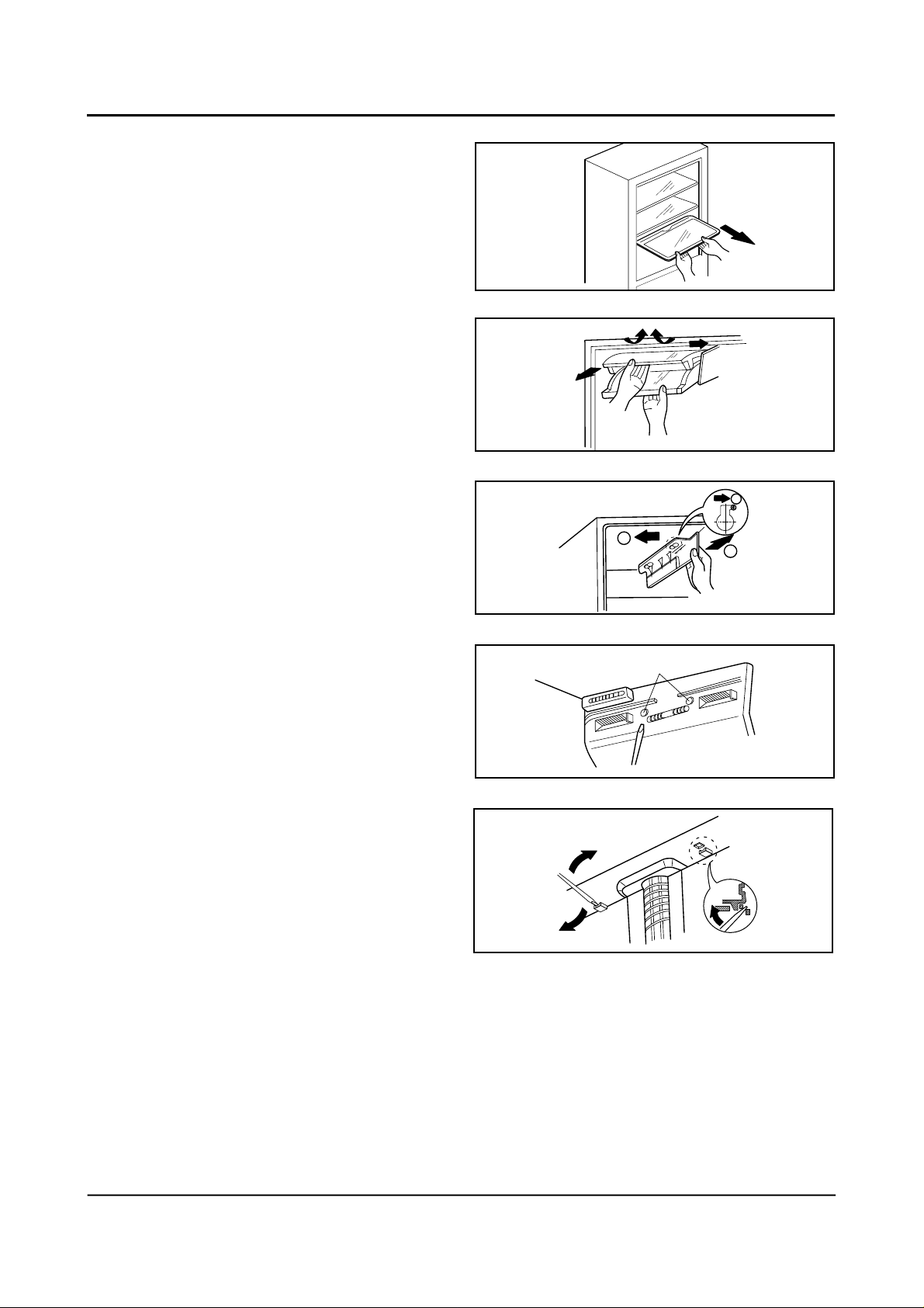
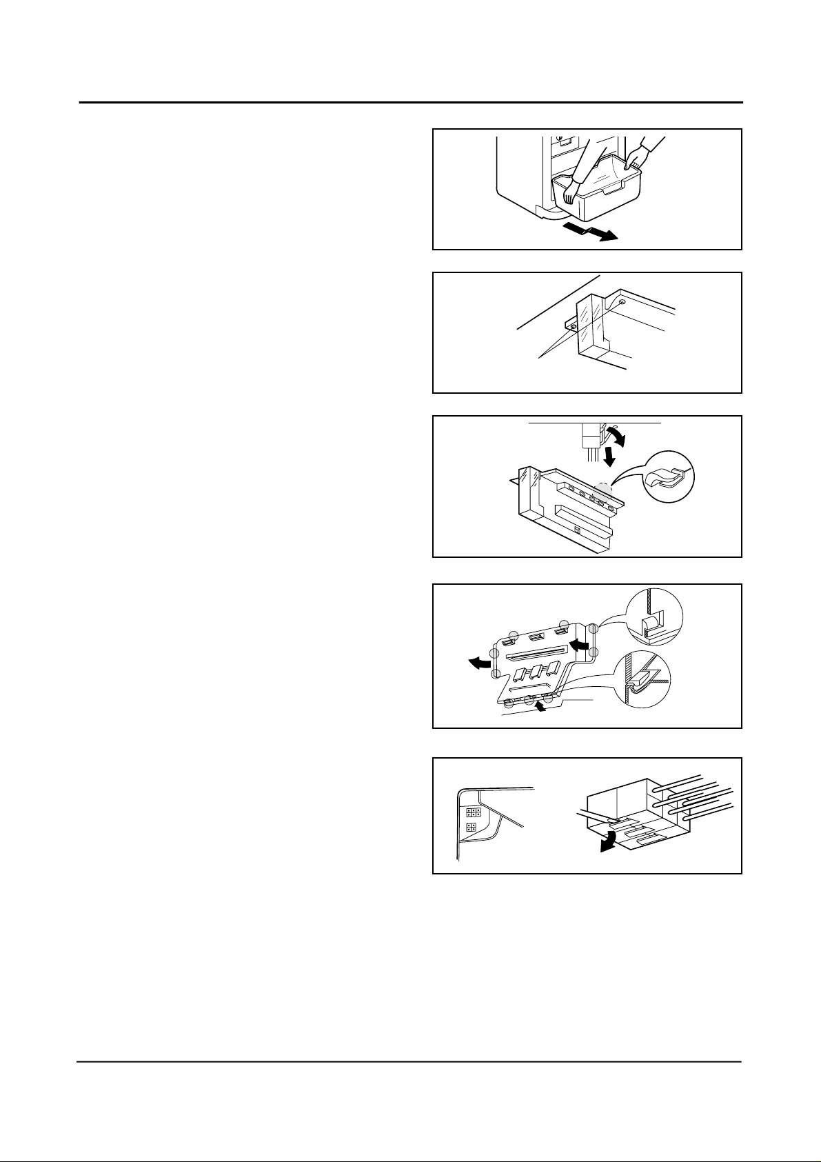
3. Disassembly of the cooling cycle in the refrigeration room
1. Take out food stuffs and trays from
refrigeration room.
2. Bend the cover of chilled compartment and
remove the left axis.
3. Move the holder of chilled compartment to the
arrow ¨and pull it out.
4. Remove 2 cap screws with (–) driver or similar
tools.
5. Remove 2 latches from the bottom of the cover
in the front of evaporator.
1
1
2
2 screws
54 Samsung Electronics
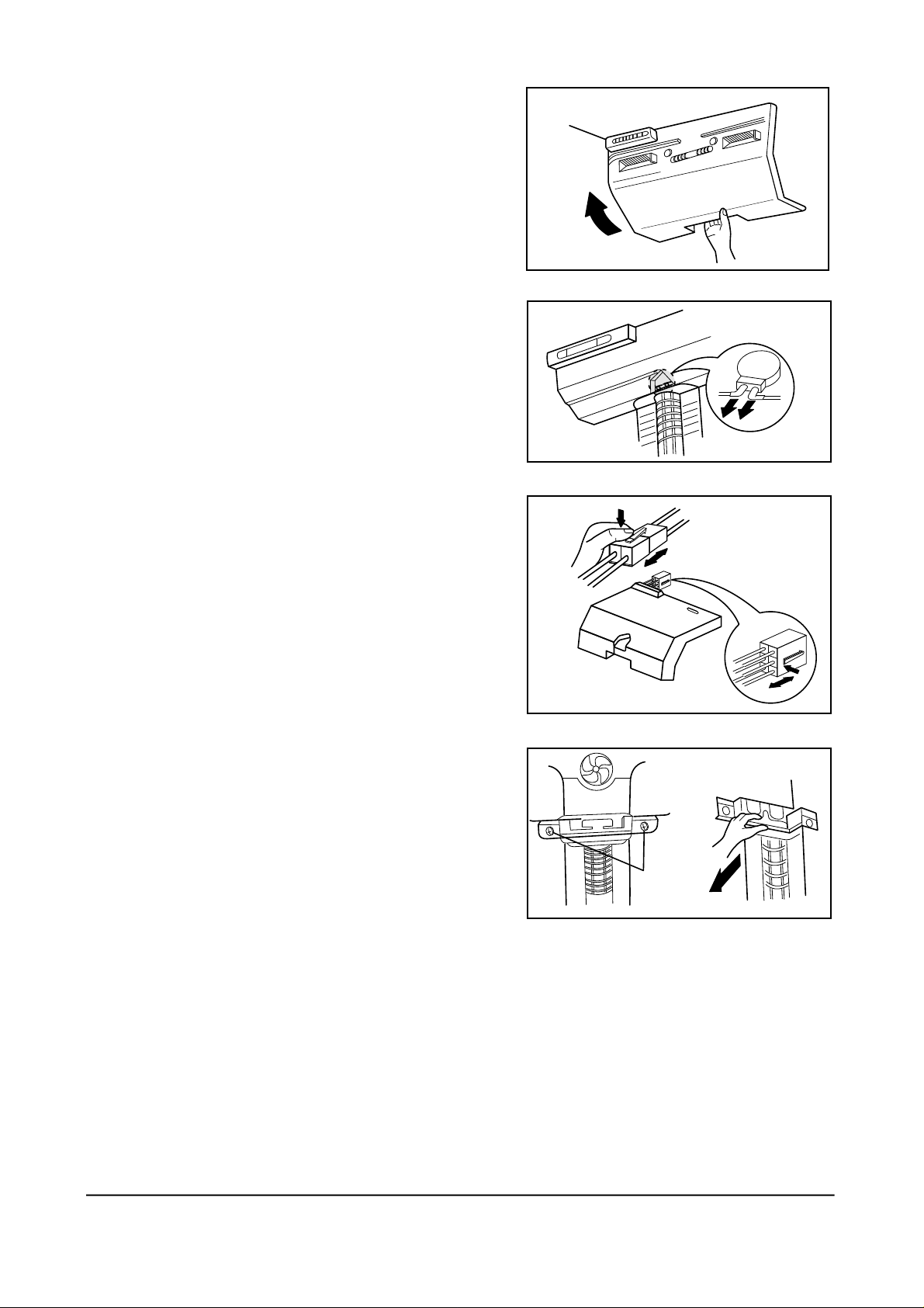
6. Remove the evaporator cover by pulling out the
bottom of the evaporator cover.
7. Remove the housing of wires from the center of the
cooling cycle unit and remove the terminal from the
geared motor.
8. Pull forward the insulating material of the cooling
cycle unit and remove the wire terminal and insulating
material.
9. Remove 2 screws securing refrigerator duct and pull it
out by following the arrow.
Remove 2 screws
Samsung Electronics 55
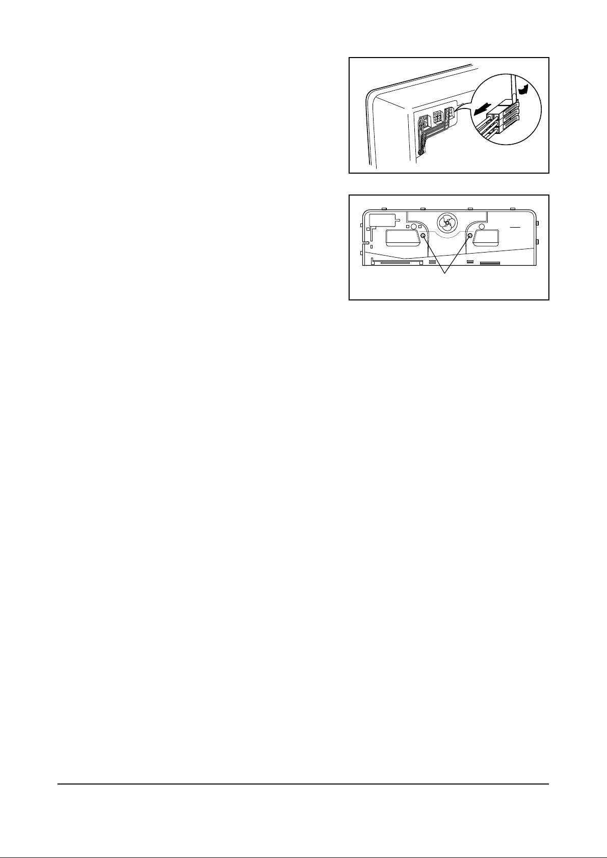
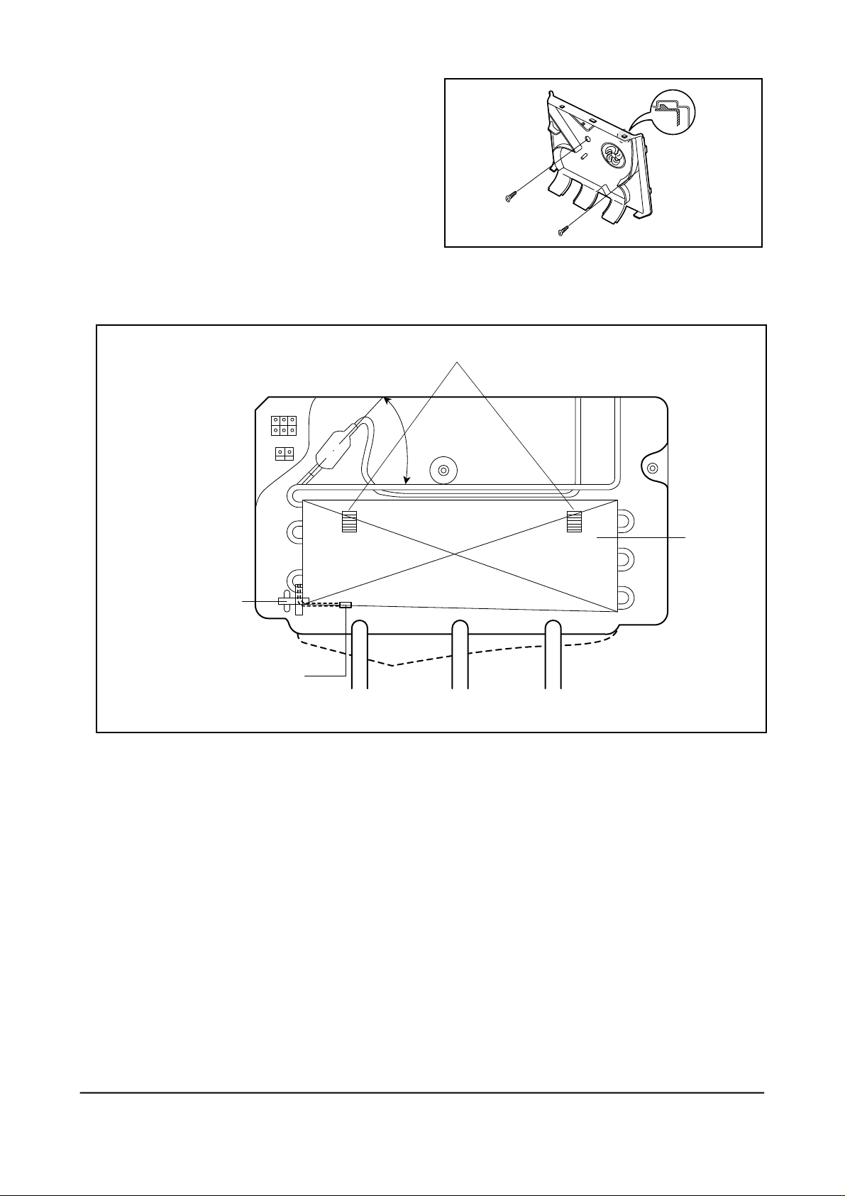
10. Remove the wire terminal from the left top of
refrigeration room
11. Remove 2 screws securing the back cover of cooling
cycle unit and remove the left and right latches with
(–) driver.
latch
Remove 2 screws
56 Samsung Electronics
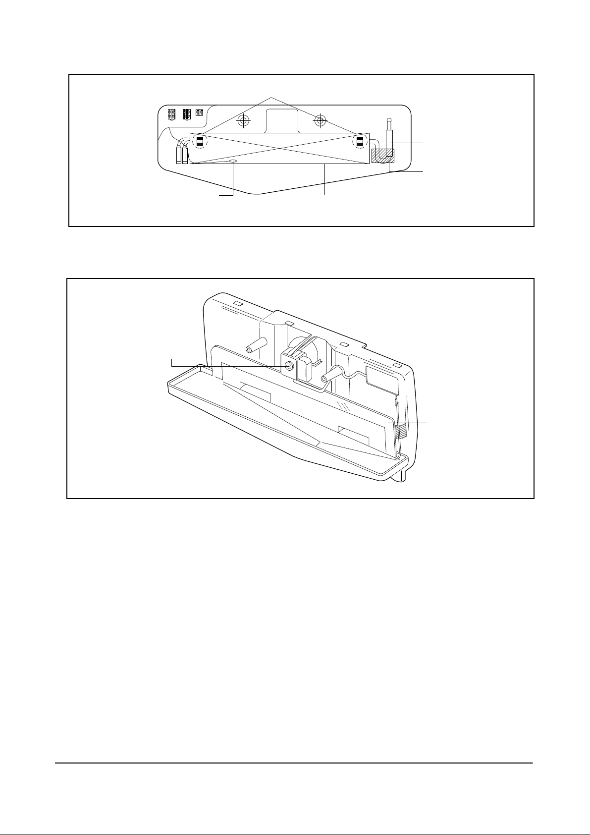
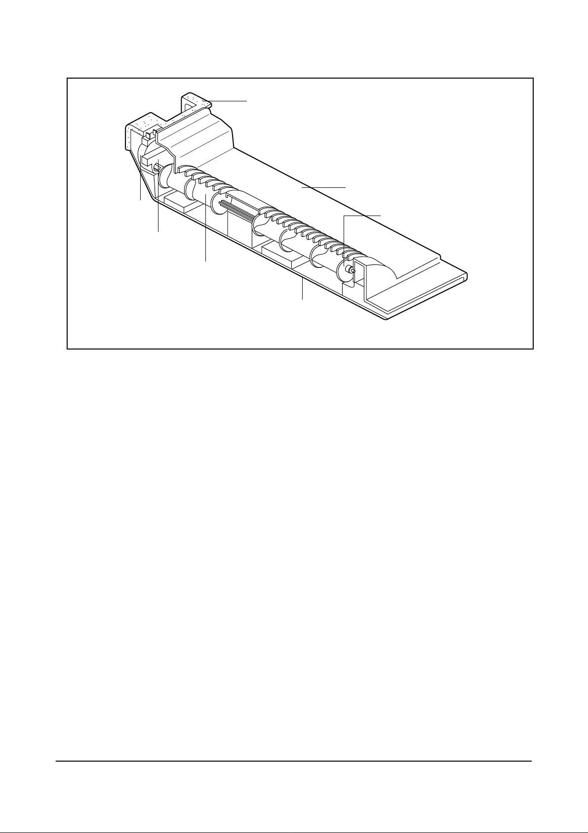
■ Cooling cycle unit assembly in the refrigeration room
2 holders securing evaporator
Temp. sensor
EVAP
■ Cooling cycle unit cover assembly in the refrigeration room
Absorber
sound(Noise protector)
TAPE-AL
(Groove for preventing
small ice when
defrosting)
Noise protector
Frost spreading
protection
Samsung Electronics 57
■ Rotating duct assembly in the refrigeration room
Seal-air
Cover-duct, REF
Motor-Geared
Reed S/W
Washer(Prevention noise)
Blade-air
Seal-duct, RE
(Prevention Temp.
distribution)
58 Samsung Electronics
4. Disassembly of the cooling cycle unit in the freezer
1. Take out the case from the freezer.
2. Remove 2 screws from the holder of the cooling
cycle unit.
3. Pull out the holder of the cooling cycle unit and
disconnect wire terminals.
2 screws
①
②
4. Remove the latch of the cooling cycle unit cover
from the bottom.
5. Remove each terminal from the top of the
left wire assembly.
③
①
②
Samsung Electronics 59
6. Remove 2 screws from the back cover of the
cooling cycle unit and remove the latch with (–)
driver.
■ Assembly of the cooling cycle unit in the freezer
EVAP holder
Maintains 45˚
(Coolant & noise
reduction)
Temp. Fuse
Temp. Sensor
EVAP
60 Samsung Electronics
 Loading...