

Page 1
6. Circuit Descriptions
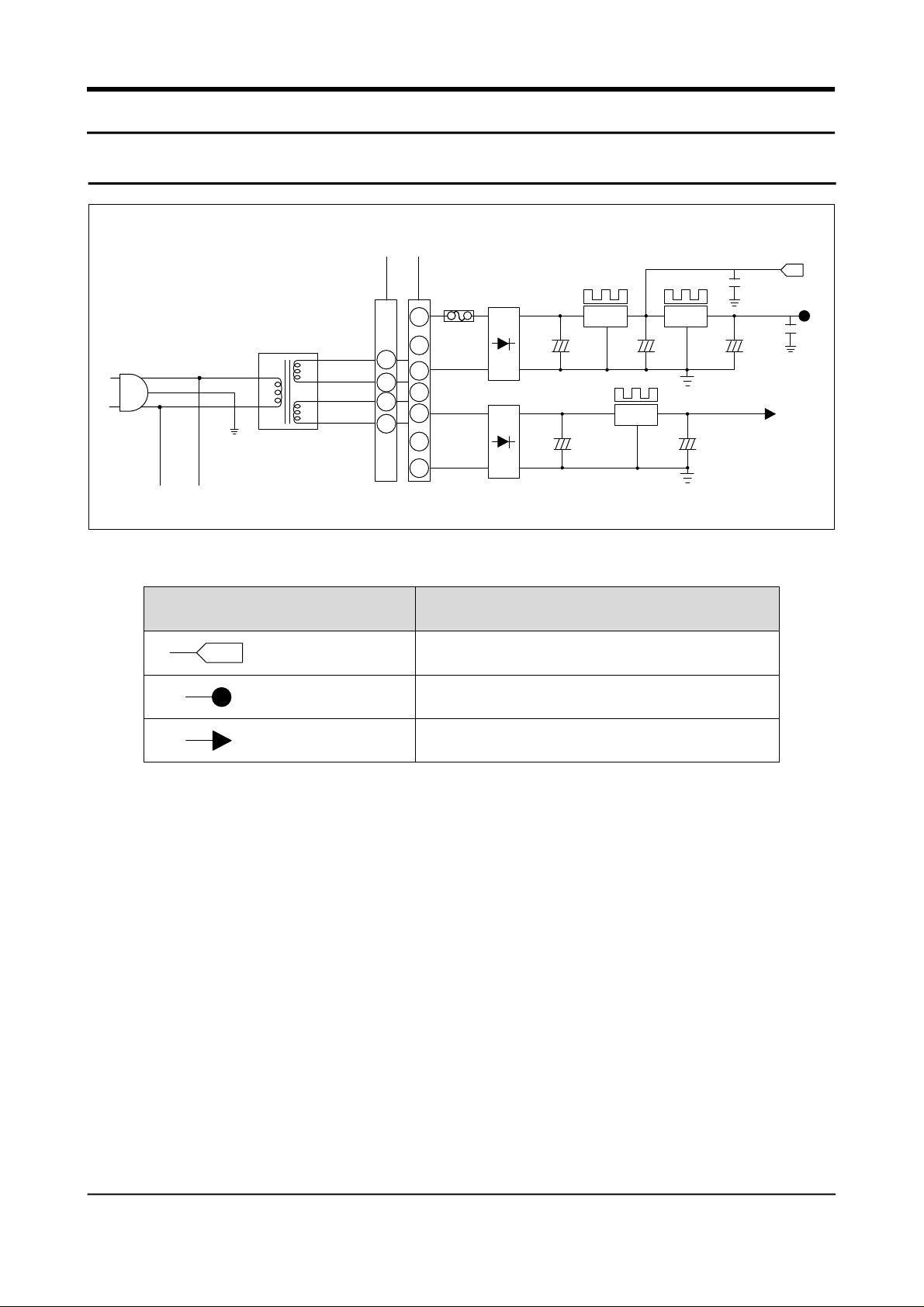
1. Power circuit
WHT GRY
GRNREDBLK
L V T
CON1
BLK
BLU
(DC12V)
C107
470uF
25V
V12
(DC12V)
C109
104
+12
Vcc
(DC5V)
BD05-08
1N4004 X 4
1
FUSE2
250V 0.5A
1
3
3
5
5
7
1N4004 X 4
C103
BD01-04
7
HEAT-STICK
+
C
C106
1000uF
35V
7812
(MC7805)
IC02
HEAT-STICK
7812
(MC7812)
HEAT-STICK
7805
(MC7805AC)
+
IC03
ICO1 +
IC03
C
470uF
25V
104
+
Circuit used
+12
Voltage
(DC 12V)
Vcc (DC 5V)
V12 (DC 12V)
Relay Operation
Power around MICOM & Sensor Detector
LED Display & S/W Detector
The input AC voltage of DC-trans secondary registers 15V at CON1 between ①~③. The rectified
voltage passed through BD05 ~ 08 becomes DC 12V through volt age regulator MC7812(IC02). The
power(DC12V) is supplied to the relay operation power block. Then, DC 5V is genetatel and supplied
to the power around micom and sensor detector through 7805(I C03).
The rectified voltage passed through BD01~04 passes through 7812(IC01). Then, DC12V is supplied to
LED display and switch detector.
18 Samsung Electronics
Page 2
2. Oscillator
30P
30P
Port
Oscillating Fr equency
Xin
Xout
±0.5% Error
3. Reset Circuit
R201
1K
KA7533
C203
1µF/25V
Port
x-tal
30
31
4.00MHz
4.00MHz
R202
29
10K
C202
104
Voltage
Xin
Xout
RESET
It is designed for clock generation and time
calculation for synchronizing transmission and
reception on the logic elements inside the MICOM.
If the X-TAL specification changes, MICOM may
make an error. The standard components should be
used.
When power is supplied to MICOM, reset circuit
initializes RAM and other parts on MICOM to
initialize all programs. Reset voltage maintains
“low” for hundreds of µsec comparing to MICOM
Vcc voltage when power is input. It also maintains
“high”(5V) during normal operation. But, when Vcc
drops to 3.3V, reset port becomes “low”.
Xin
Xout
4. Door S/W Detector
F-DOOR S/W
R-DOOR S/W
5V
5V
CON06
Vcc
R401(4.7K)
R403(4.7K)
R402
10K
R404
10K
C401
104
C402
104
7
8
Samsung Electronics 19
Page 3
DOOR
F
Door Conditions
CLOSE
OPEN
Door S/W Contact
OPEN
CLOSE
MICOM
PIN NO
# 7
Micom Input Voltage
“LOW”
“HIGH”
CLOSE
R
OPEN
OPEN
CLOSE
“LOW”
# 8
“HIGH”
1) If door is open, door S/W contact is closed. Then MICOM receives “low” signal and detects
door open.
2) If door is closed, door S/W contact is open. Then MICOM receives “high” signal and detects
door close.
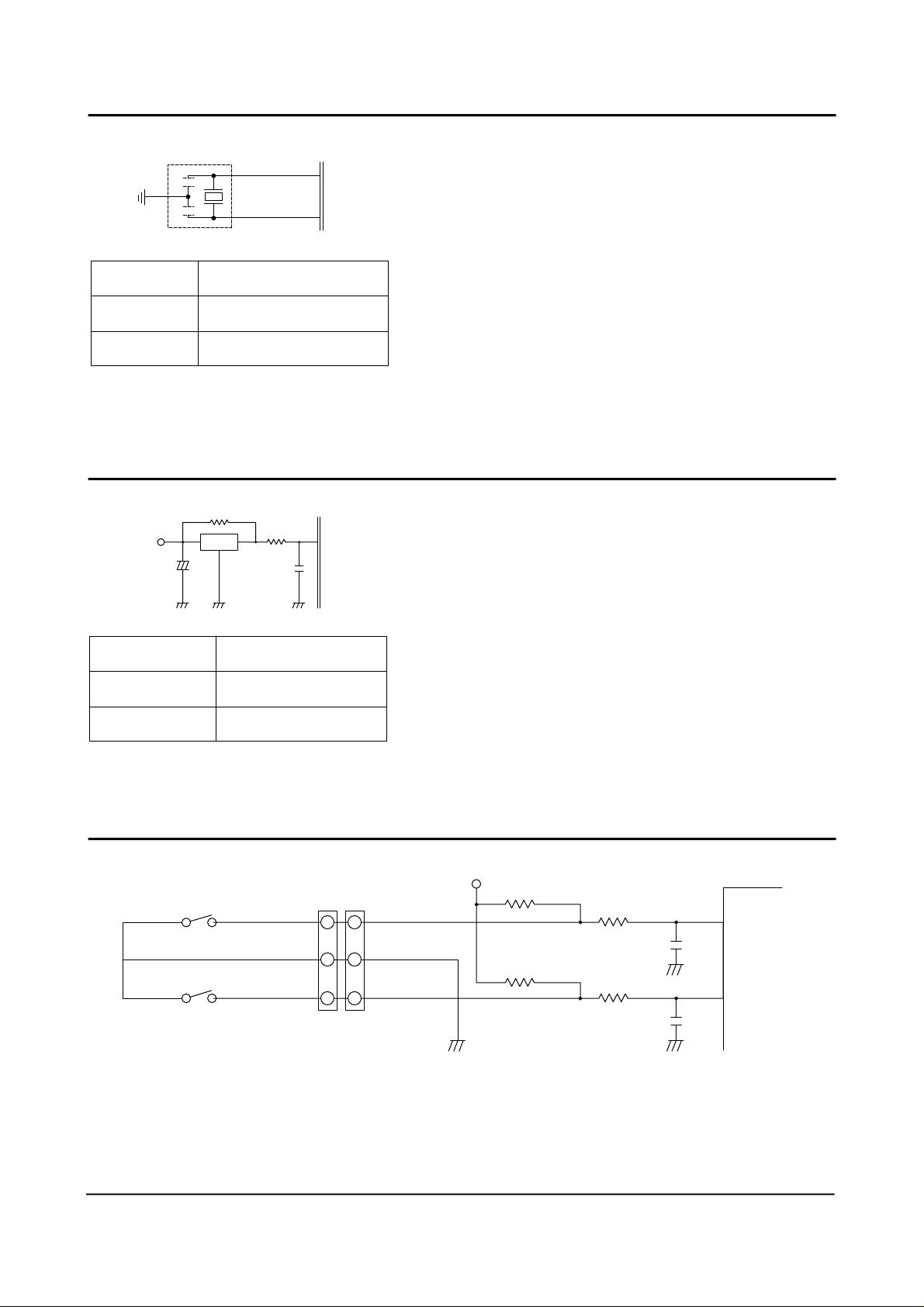
5. “V” Motor Position Detector(Reed S/W)
CON 02
REED S/W
7
6
5
Vcc
R405
4.7K
R406
10K
C403
104
43
1) The position of “V” motor for controlling the G.A–fuzzy of the temperature in the
refrigeration room is detected by the reed switch.
2) When MICOM Pin 43 changes ‘high’ to ‘low’ by the operation of fan, MICOM detects the
position of “V” motor.
20 Samsung Electronics
Page 4

6. Temperature Sensor
R2-ROOM
R1-ROOM
THERMISTOR
F-ROOM
THERMISTOR
R / DEF - SONSOR
THERMISTOR
F / DEF - SONSOR
4
3
2
1
1
2
3
4
565
CON2
4
3
2
1
CON3
1
2
3
4
6
Vcc
Vcc
Vcc
Vcc
Vcc
"A"
R301
10K-F
R303
10K (F)
R305
10K (F)
R307
10K (F)
R309
10K (F)
Vcc
( Air Sensor)
R311
10K (F)
R302
10K
R304
10K
R306
10K
R308
10K
R310
10K
R312
10K
104
C09
104
104
104
104
104
C301
C302
C303
C304
C305
C306
60
P64
59
P63
62
P66
61
P65
58
P62
63
P67
When Sensor is open
MICOM input “HIGH”
When sensor is cut off
MICOM input “LOW”
1) The sensor uses the characteristics of thermistor. If temperature goes higher, resistance goes
lower. On the contrary, if temperature goes lower, resistance goes higher.
2) MICOM input voltage is counted by sensor as follows.
VF = X Vcc
RTH
RTH + R24
(VCC : 5V, RTH : Sensor reisitance)
3) For the resistance information on temperature and MICOM input voltage, please refer the
conversion table. (Page. 41)
Samsung Electronics 21
Page 5

7. Key scan and display circuitry
IC04
R502
1.2K
3
4
5
6
7
8
9
GND VCC
UDN2003(2803)
IC05
1
2
3
4
5
13
10
16
15
14
13
12
10
C23
104
18
17
16
15
14
6
9
C501
3K
P04
P03
P02
P01
P00
P75
P74
P73
P72
P71
P70
13
12
11
10
9
6
5
4
3
2
1
R503
1K
1) Key scan and display operation
+12
GRID 05
GRID 04
GRID 03
GRID 02
GRID 01
R501
3K
R04
4. 7 K
CON7
(XH-11P)
10
11
10
10
9
9
9
4
4
4
3
3
3
2
2
2
Quick
REF
HIGH
Alarm
HUMI
X-Flow Quick FRE
Quick
Quick REF
FRE
1N4148
1N4148
1N4148
1N4148
1N4148
S/W01
S/W02
S/W03
S/W04
S/W05
X1 X2 X3
1
1
1
5
5
5
6
6
6
7
7
7
8
8
8
11
11
KEY INPUT
X4 X5 X6
F Temp. R Temp.
C C-N N N-W W
C C-N N N-W W
As shown in the following waveform, MICOM pins #2 ~ #6 output are high for 2msec per 10msec.
MICOM pin #2 → #3 → #4 → #5 → #6 output repeats. The signal is output through IC05(UDN
2981A). At that time, the peak to peak voltage of square signal registers around 11V. The grid #1 ~#5
waveforms are as follows.
2 m Sec 8 m Sec
V
11V
Grid #1
Grid #2
Grid #3
Grid #4
Grid #5
O
V
O
V
O
V
O
V
O
Refrigerator Display
t
Freezer Display
t
Letter Display
t
“V” Function Display
t
“V” Function Display
t
22 Samsung Electronics
Page 6

2) Key Scan
The grid waveform of each output is supplied to each button line through switching diode
(IN4148). The grid #1 signal goes to the setting button of refrigerator. Then, refrigerator button
is pressed, around 4.5V goes to IC05(UAN2981A) pin 8 through key input line. MICOMdetects
the refrigerator button pressed after MICOM pin1 receives the signal.
8. Load Operation
RY09
RY01
RY02
RY03
RY04
RY05
RY06
RY07
RY08
+12
+12
(DC12V)
C27
104
IC06
18 1
11 8
12 7
13 6
15 4
15 3
17 2
18 1
Vcc GND
ULN2803
IC07
17 2
IC06
(R-DEF-HET)
14
(R-LAMP)
(F-LAMP)
(COMP)
P05
16
P07
18
P11
19
P12
P14
21
22
P15
23
P16
24
P17
17
P10
P06
R03
C24
10K
104
(COMP-COOL FAN)
R
C
SWING MOTOR
I
N
E
(R CIRCLE-FAN)
T
W
O
R
K
(F CIRCLE-FAN)
9
AC1
C25
R02
10K
104
(F-DEF-HET) 15
R-Defrost heater
COMP COOL FAN
SWING MOTOR
R-C/FAN
R-LAMP
F-LAMP
F-C/FAN
COMP.
F-Defrost heater
CON9
RED
CON10
CON8
9
9
7
7
5
5
3
3
1
1
9
9
7
7
5
5
3
3
SPK1-4
SQ-1201
1
1
5
5
3
3
1
1
V12
If MICOM outputs “high” signal to driver-IC(ULN 2803) according to each load operation
conditions, IC turns on and DC 12V flows to ground through the relevant relay coil. Then, core is
magnetized by the coil current, and relay contact switches on. When relay contact is on, AC POWER
is supplied to the relevant operation load, then which will be activated. If MICOM outputs “low”
signal, load operation stops with the relevant relay contact off.
Samsung Electronics 23
Page 7

1) Compressor and Defrost Heater
RY08
AC POWER
NC NO
COMP
F-Defrost heater
R-Defrost heater
CC
NC NO
RY09
RY01
As above block diagram, the commons of compressor relay(RY 08) and defrost heater relay(RY 09,
RY 01) are respectively connected to AC POWER line. If relay is not activated(OFF) contact
maintaills NC, and compressor and defrost heater are all off, activated and contact is switched on.
Then, AC POWER is supplied to compressor activated. On the contrary, if defrost heater relay
operates, defrost heater is activated. Compressor and defrost heater do not operate simultaneously
under any conditions of relay.
RELAY
COMP
on
Defrost H
off
Load
Comp Operation
Defrost-Heater Power Off
Remark
on
off
off
on
on
off
Comp off, Defrost-Heater Off
Defrost-Heater On
Comp Off, Defrost-Heater Off
Comp Power Off
24 Samsung Electronics
Page 8

9. Other option functions
Vcc
49
P50
50
P51
P52
P53
P54
P30
P31
P32
P33
P34
P35
P36
P37
51
52
53
33
34
35
36
37
38
39
40
R33 - 40
47K X 8
R12-16 1K X 5
51 41 31 21 11
52 42 32 22 12
53 43 33 23 13
54 44 34 24 14
55 45 35 25 15
56 46 36 26 16
57 47 37 27 17
58 48 38 28 18
10. PCB Sub Ass’y(Inverter PCB)
Temperature and function values are changeable by using
main PCB switching diode.
• Note : If possible, do not change be cause the values have
been set in factory. When changing option functions,
power should be turned off.
(Only initial power-on allows reading option
function)
TH-SW
C4
D8
D10
R9
R8
R3
R2
F1
C1
LF1
RT1
D1 D2
D3
D4
+
C3
R1
Q4
C8
C2
R10
PT2
D5
DAC
R4
PT3
ZD1
Q1
R5
CH2PT-1
CH1
Q2
R7
Q3
R6
D11
RT2
C6C5
D9
Samsung Electronics 25
Page 9

1) Power circuit
PCB sub ass’y (Inverter PCB) is activated with AC POWER input when the refrigerator door is open
and R-lamp relay(RY05) is activated. If the AC POWER is supplied to the power block, the smooth
capacitor(C3) gets around VOLTAGE DC(VOLTAGE AC X 2) AC POWER through rectification.
2) Lamp
If power is supplied to the PCB sub ass’y, diac(DB4) is activated. When C4 is over 35C/DC, voltage
is supplied to TR Q2 base by the continuity of diac. Then, TR Q2 is activated.
When TR Q2 is activated, current flows to C5 – C6 – CH1 – PT1 – R9. At that time, current flows to
PT2 and PT3.
If the discharge of capacitor C6 is completed, reverse current flows to PT2 and PT3 and TR Q2 turns
off TR Q3 turns on. The current flows to PT1 – CH1 – C6 – C5 – C8.
Lamp light up by the repetition of TR Q2, Q3 on/off. Its frequency range is 30~40KHz during
on/off.
3) PTC and PTC protector
PTC is designed to smooth the lighting and to lengthen lamp’s life by heating filament of lamp. The
PTC protector prevents damage from PTC by cutting off power through triac if filament emits high
voltage at the beginning of lighting.
To check the PTC, measure resistance (150Ω ± 25% is normal). But, PTC resistance can be challged by
the ambient temperature and PTC operation. The above resistance value is counted in 20 sec after
lamp is off with the temperature 25˚C.
26 Samsung Electronics
Page 10

4) Troubleshooting
Precautions
1. Is the power cord well connected to wall outlet?
2. Be careful of high-voltage discharge because high voltage DC power is supplied to SUB-PCB.
① When the light dosen’t come on in the refrigerator
Start
Is power supplied to
sub-PCB?
Y
N
Is power supplied to
smoother C2?
N
Is TH-S/W normal?
Y
Does lamp oscillate
Y
Check the power
at 35±5KHz?
N
Check PTC.
Replace lamp
Replace TH-S/W
✻ PTC should be inspected before replacing lamp.
✻ Be careful of high voltage discharge, when repairing unit.
N
Check wires and
main PCB relay
Y
Repair C6, C7 or
PTC(RT1)
Samsung Electronics 27
 Loading...