

Page 1
Reference
Reference1
Reference2
NO
C
NC
Coil bisection
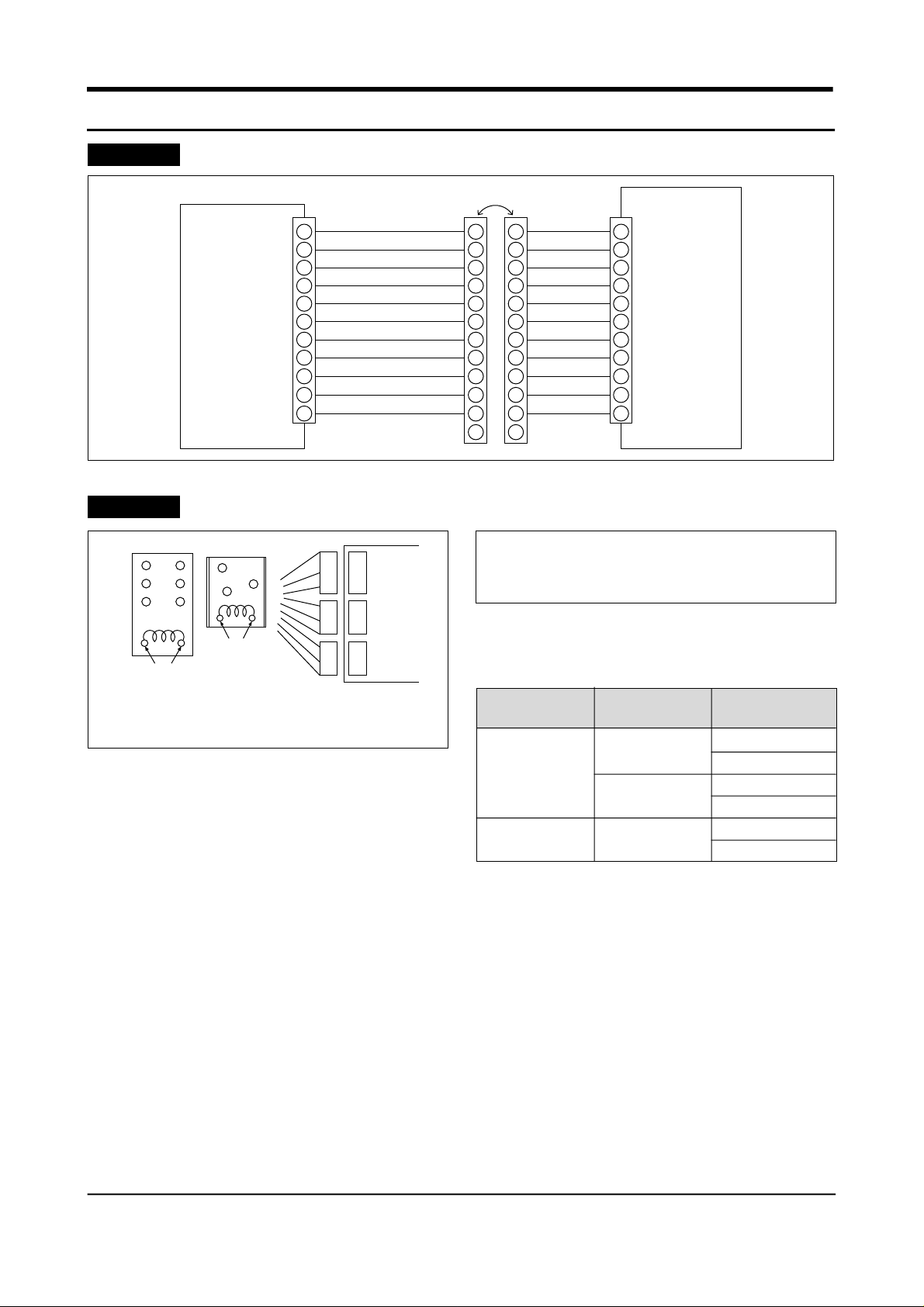
The connection of DOOR-CABI
BLK
1
2
BRN
3
MAIN
PCB
RED
4
ORG
5
YEL
6
PNK
7
BLU
8
PUR
9 9 9
GRY
10
WHT
11
S/BLU
CON7
Inspection of Relay
Coil bisection
Measure after
separation
(Relay Movement)
CON9
CON10
MAIN PCB
CON8
10
11
12
1
1
2
2
3
3
4
4
5
5
6
6
7
7
8
8
10
11
12
10
11
1
2
3
4
5
6
7
8
9
BLK
BRN
RED
ORG
YEL
PNK
BLU
PUR
GRY
WHT
S/BLU
PANEL
PCB
* First separate the housing connected to the
main PCB CON C8, 09, 10 and measure the
following items.
1. M e a s u re the coil bisection of the relay and
check whether it works.
2. Measure the apex bisection for open circuit.
Apex category The voltage of
coil bisection
DC 12V(Operation)
Apex 3
DC 05V(Standstill)
Apex 2
DC 12V(Operation)
DC 0V(Standstill)
Judging the apex
bisection
C:NO SHORT
C:NC OPEN
C:NO OPEN
C:NC SHORT
SHORT
OPEN
Note) C →Common, NO → Normal open, NC → Normal close
3. When it operates as above, it is normal and
when it does not operate, report the
corresponding relay.
36 Samsung Electronics
Page 2
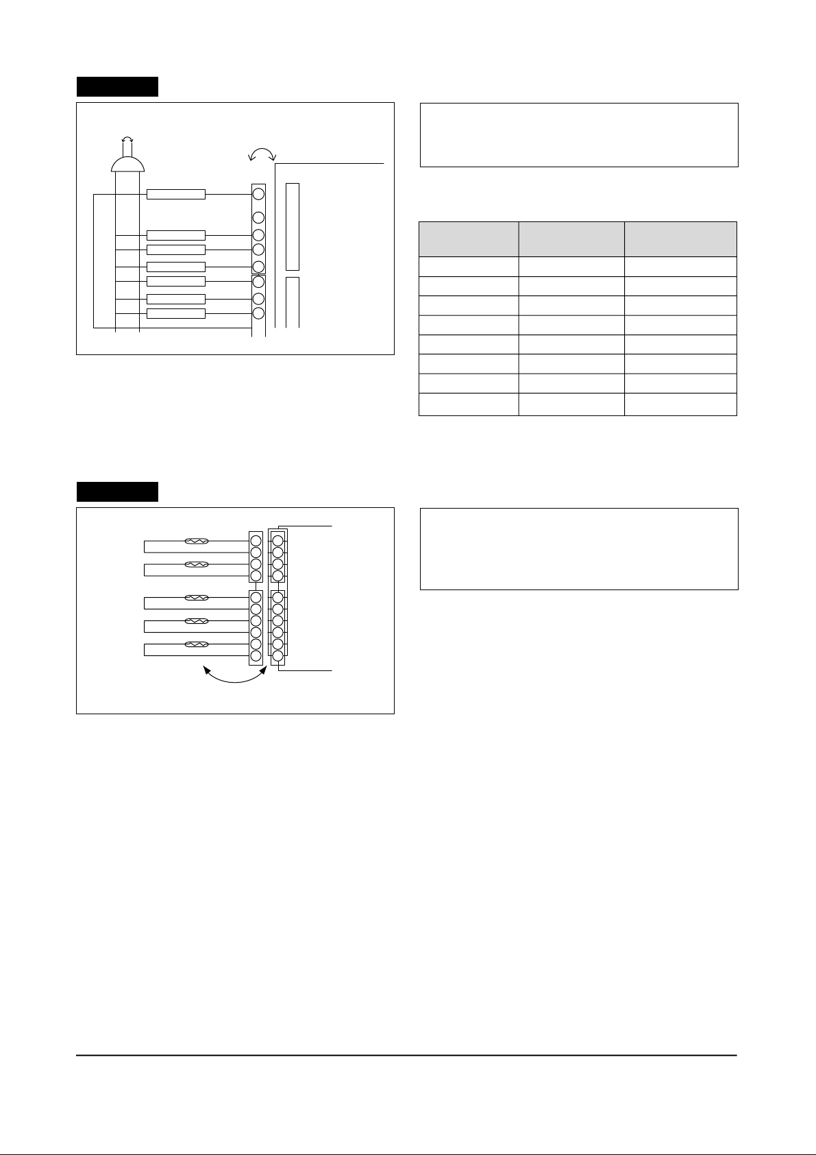
Reference3
Short
Check for malfunctioning of the subordinate
Measure after separation
* Cut off the power code, separate the housing
from the main PCB CON 08, 09, 10 and
measure the following.
CON9
R-Defrost heater
SWINT MOTOR
R-C/FAN
RED
Note) The compressor is impossible to measure resistance by the
running and starting condenser.
Reference4
R-Lamp
F-Lamp
F-C/FAN
COMP.
Inspection of the sensor
R2 ROOM
R1 ROOM
F - ROOM
R / DEF - SONSOR
F / DEF - SONSOR
RED
8
7
5
3
1
CON10
9
7
5
4
3
2
1
CON3
1
2
3
4
5
6
Measure after separation
CON2
4
3
2
1
MAIN PCB
1
2
3
CON3
4
5
6
CON9
CON10
1. Measure resistance between the terminals and
check for malfunctioning of L/W.
Subordinate
R Defrost heater
F Defrost heater
Comp
Swing motor
R-Circulation fan
F-Circulation fan
R-Lamp
F-Lamp
M e a s u r e m e n t
t e r m i n a l
CON9 ⑨& CON10
CON8 ③& CON10
CON8 ⑤& CON10
CON8 ①& CON9
CON8 ①& CON9
CON8 ①& CON10
CON8 ①& CON9
CON8 ①& CON10
Evaluation of mea-
surement result
③
0Ω or ∞Ω(defect)
③
Impossible to measure 0Ω indicator
⑤
0Ω or ∞Ω(defect)
⑤
③
⑦
①
⑨
* Separate the housing connected to main PCB
CON2 and CON3.
* Resistance value lowers while temperature
rises, because it is a NTC type sensor.
1. R1 sensor measures resistance of CON2
between ①~②.
2. R2 sensor measures resistance of CON2
between ③~④.
3. Freezer sensor measures resistance of CON3
between ①~②.
4. R-defrost sensor measures resistance of CON3 between ③~④.
5. F-defrost sensor measures resistance CON3 between ⑤~⑥.
6. The measurement value above is calculated by comparing th e present temperature of the sensor and
the temperecture table in specification found in the manual.
Samsung Electronics 37
Page 3

Reference5
Checking the Door S/W
(Refrigerator Bulb)
1. Open the door and check if the freezer bulb
F - Door S/W
1
1
22
CON6
MAIN
PCB
DC 12V
turns on.
2. Press the Door S/W and check if the freezer
bulb turns off.
3. Close the door of freezer and repeat 1 and 2 for
refrigerator.
3
R - Door S/W
3
4. If there is a problem, check bulb and door S/W.
5. Check wire connection.
(Micom signal)
1. Check if CON6 ① and ③is 0V DC after closing the F·R doors.
2. Check if CON6 ①is 12V DC when opening F door.
2. Check if CON6 ③is 12V DC when opening R door.
3. If there is problem, check door S/W and wire connection.
Reference6
Forced starting & forced defrosting
TEST S/W
(Forced starting)
* This function is used to turn on the comp and
fan immediately regardless of the temperature
of freezer.
1. Press the button on the PCB after removing the
main PCB cover from the upper part of
refrigerator.
2.
Buzzer will sound to indicate the forced starting.
(Forced defrosting)
* This function is used to turn on the defrosting
regardless of defrost time.
1. Press the button twice during forced starting.
Then, defrosting is performed.
2. If the button is press 3 times during Rdefrosting, F-defrosting is also performed at
the same time.
3. If the button is pressed 4 times during R-f
defrosting, test mode is released.
38 Samsung Electronics
Page 4

Reference7
Sensor Short : Micom 0V.
Sensor Open : Micom 5V.
Sensor resistance and voltage conversion table for temperature
(Sensor pressure voltage 10KΩ – Voltage converted by the F-reference)
* Voltage conversion table depends on H/W structure of MICOM port input voltage.
✽ Sensor partial pressure resistance 10KΩ
TEMP.
– 35
– 34
– 33
– 32
– 31
– 30
– 29
– 28
– 27
– 26
– 25
– 24
– 23
– 22
– 21
– 20
Resistance KΩ ± 1%
68.648
65.011
61.595
58.384
55.366
52.526
49.854
47.337
44.967
42.733
40.626
38.640
36.765
34.995
33.323
31.743
Voltage(V)
4.364
4.333
4.301
4.268
4.235
4.2
4.164
4.127
4.09
4.051
4.012
3.972
3.93
3.888
3.845
3.802
TEMP.
– 13
– 12
– 11
– 10
– 9
– 8
– 7
– 6
– 5
– 4
– 3
– 2
– 1
0
1
2
Resistance KΩ ± 1%
22.832
21.814
20.848
19.932
19.062
18.237
17.453
16.709
16.001
15.328
14.688
14.080
14.501
12.949
12.424
11.924
Voltage(V)
3.477
3.428
3.379
3.329
3.279
3.229
3.178
3.127
3.076
3.025
2.974
2.923
2.872
2.821
2.77
2.719
TEMP.
9
10
11
12
13
14
15
16
17
18
19
20
21
22
23
24
Resistance KΩ ± 1%
9.016
8.673
8.345
8.032
7.732
7.446
7.172
6.910
6.659
6.420
6.190
5.970
5.759
5.557
5.363
5.178
Voltage(V)
2.37
2.322
2.274
2.227
2.18
2.134
2.088
2.043
1.998
1.954
1.911
1.869
1.786
1.786
1.745
1.705
– 19
– 18
– 17
– 16
– 15
– 14
30.250
28.838
27.502
26.237
25.040
23.906
3.757
3.712
3.666
3.62
3.573
3.525
3
4
5
6
7
8
11.447
10.993
10.559
10.146
9.752
9.375
2.668
2.618
2.567
2.518
2.468
2.419
25
26
27
28
29
30
5.000
4.829
4.665
4.508
4.357
4.212
1.666
1.628
1.59
1.553
1.517
1.481
Samsung Electronics 39
 Loading...