

Samsung SFP-FSCS120-B, SFP-GLCM202, SFP-GLCS120-B, SFP-GLCS215, SFP-GRJC User Manual
...
INSTALLATION AND OPERATION MANUAL SFP MODULES
SFP Modules
COPPER AND OPTICAL FIBER ETHERNET CONNECTORS
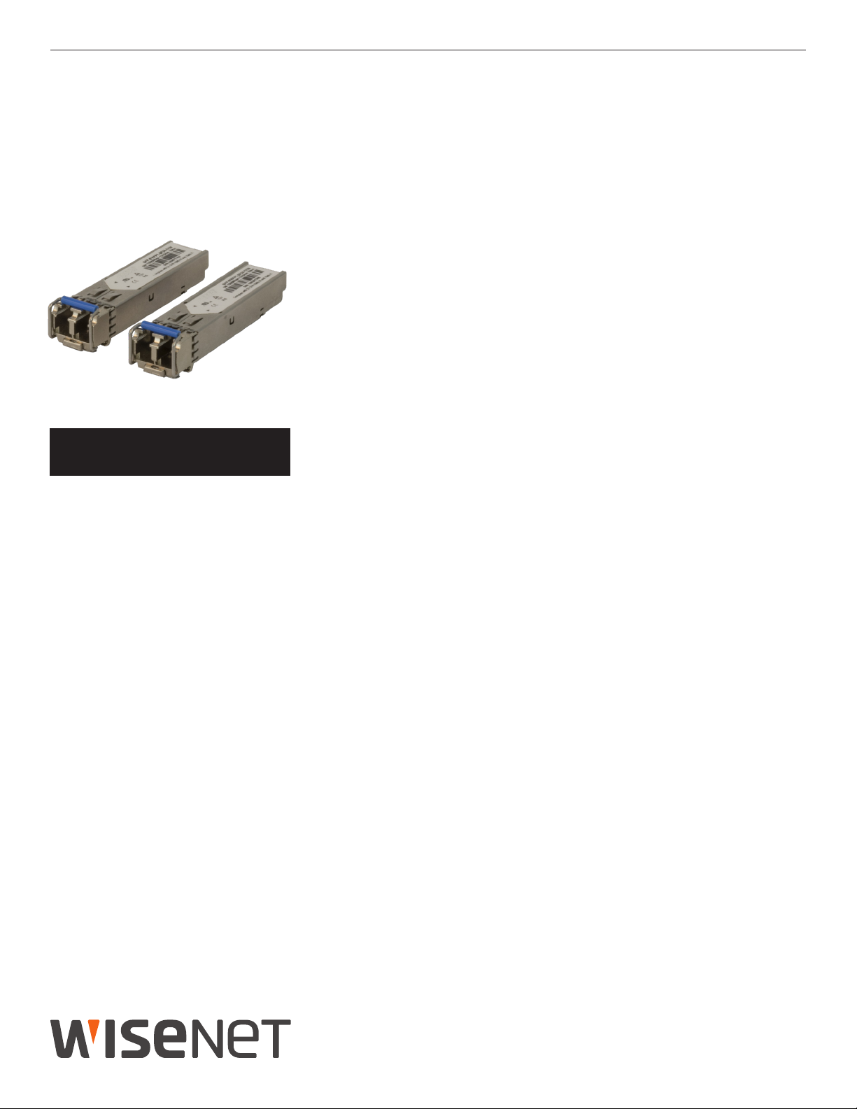
The selection of Small Form-Factor Pluggable modules allow for an optical or copper
interface when using a managed switch, unmanaged switch or media converter.
These interchangeable SFP modules are available for use with copper media,
or multimode and single mode optical fiber. The optical fiber SFP modules are
This manual serves the following
Model Names:
SFP-GRJC
SFP-FLCM202
SFP-FLCS220
SFP-FSCM102-A
SFP-FSCM102-B
SFP-FSCS120-A
SFP-FSCS120-B
SFP-GLCS215
SFP-GLCS120-A
SFP-GLCS120-B
SFP-GLCM202
available in fast Ethernet one and two fiber versions and Gigabit one and two fiber
versions. They also are available with LC or SC optical connectors.
The SFP modules have different wavelengths and optical power to offer distances
from 300 meters to 20 kilometers. These SFP modules are industrially rated to
perform in the most difficult operating environments.
See Page 2 for complete installation instructions.
INS_SFP-Series 08/12/19 PAGE 1
INSTALLATION AND OPERATION MANUAL SFP MODULESINSTALLATION AND OPERATION MANUAL SFP MODULES
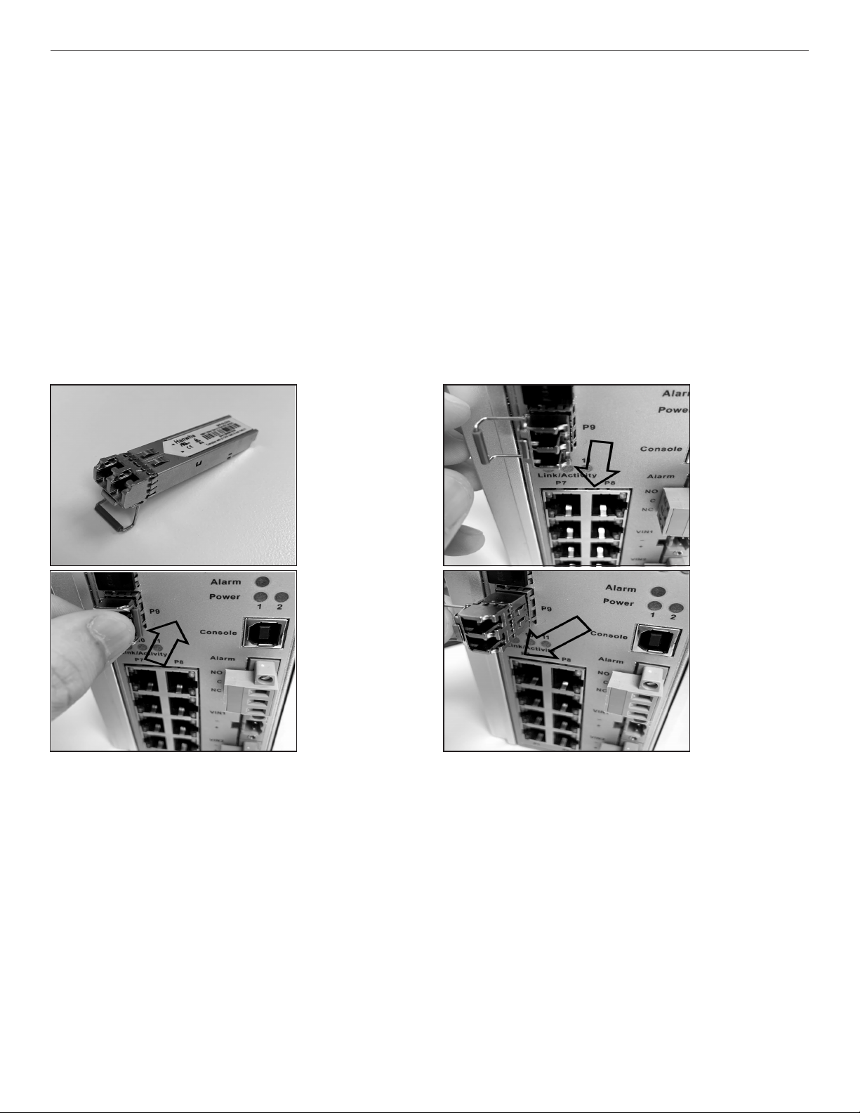
SFP-(G,F)-X-[A,B] INSTALLATION/REMOVAL
CAUTION:
- The Fiber Optic sub-module is static sensitive. Use static handling precautions when installing or removing the sub-module.
- Protect your SFP sub-modules by inserting clean dust plugs into the SFP sub-modules after the optical fiber is extracted from
them. Be sure to clean the optic surfaces of the optical fiber before you plug them back into the optical bores of another SFP submodule. Avoid getting dust and other contaminants into the optical bores of your SFP sub-modules. The optics will not work correctly when obstructed by dust.
SFP Module:
- The SFP sub-module installs in the connector cage located on the unit corresponding to the port assignment to be used.
- The SFP sub-module is keyed and can only be installed in one orientation.
- The SFP sub-module (see Figure 1) has a bale clasp that you use to secure the SFP sub-module in a connector cage.
- Check the model designation to determine if there is an "A" / "B" version of the SFP sub-module. "A" modules must be
paired with a "B" module. Modules without an "A" / "B" designation may require swapping the optical pairs to determine
the correct TX / RX polarity.
The photos used in the following sequence are intended to aid in the installation and removal of the SFP sub-module and may not
match your particular model.
Figure 1
Figure 2
Installation:
Step 1
- Flip the bale clasp up before inserting the SFP module.
Step 2 - Line up the SFP sub-module with the port and slide it
into the port. (see Figure 2)
Step 3 - When you are ready to attach the optical fiber, remove
the rubber plugs from the sub-module and save for
future use.
Note: When installed properly the SFP sub-module will lock
in place.
Figure 3
Figure 4
Removal:
Step 1 - Disconnect the optical fiber from the SFP sub-module.
Step 2 - Open the bale clasp on the SFP sub-module by press-
ing it down with your index finger as shown
in Figure 3.
Step 3 - Grasp the SFP sub-module between your thumb and
index finger and carefully remove it from the connector cage as shown in Figure 4.
Step 4 - Install the rubber plugs back into the SFP sub-module
optical bores, and place the SFP sub-module in antistatic protective packaging.
INS_SFP-Series 08/12/19 PAGE 2
 Loading...