

Samsung SF-750, SF-755P Service Manual
SERVICE
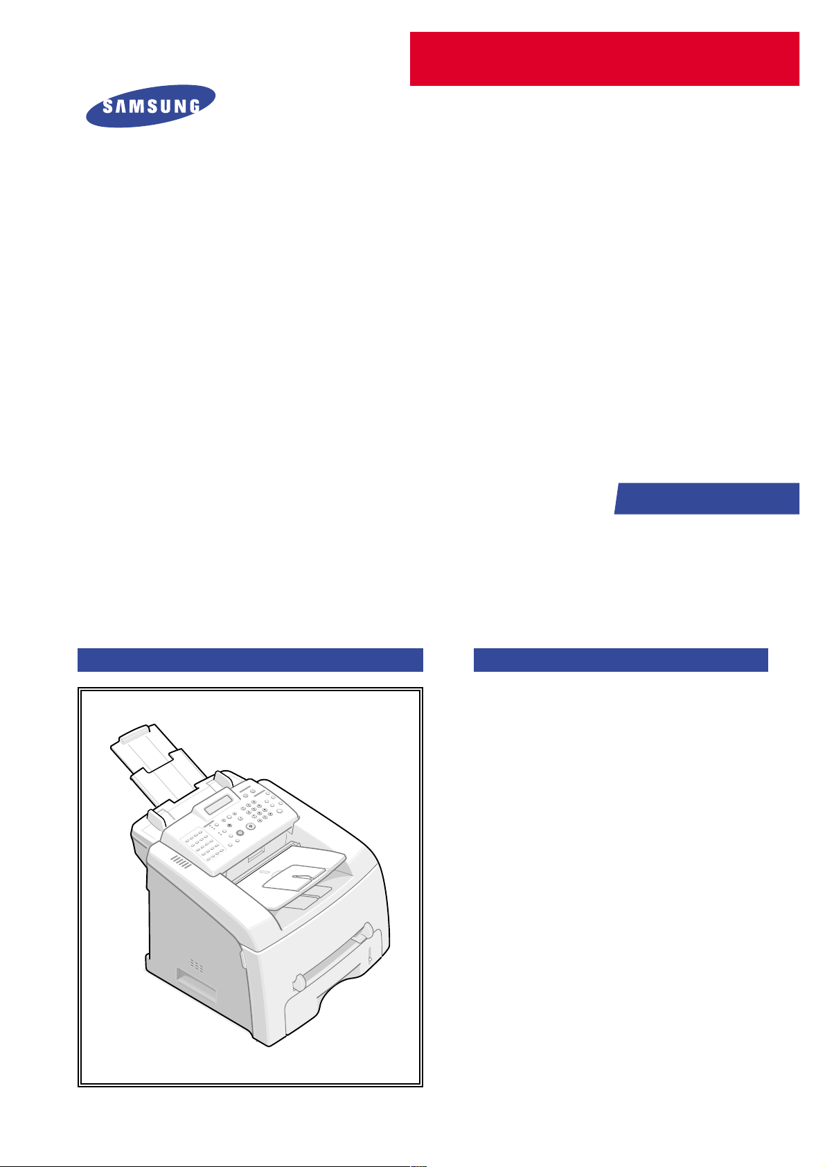
DIGITAL LASER MFP
SF-750
SF-755P
Manual
DIGITAL LASER MFP CONTENTS
1. Precautions
2. Reference Information
3. Specifications
4. Summary of product
5. Disassembly and Reassembly
6. Alignment and Adjustments
7. Troubleshooting
8. Exploded Views and Parts List
9. Block Diagram
10. Connection Diagram
1
1
1-1
Precautions
Service Manual
1. Precautions
In order to prevent accidents and to prevent damage to the equipment please read the precautions listed
below carefully before servicing the printer and follow them closely.
1.1 Safety W arning
(1) Only to be serviced by appropriately qualified service engineers.
High voltages and lasers inside this product are dangerous. This printer should only be serviced by a suitably
trained and qualified service engineer.
(2) Use only Samsung replacement parts
There are no user serviceable parts inside the printer. Do not make any unauthorized changes or
additions to the printer , these could cause the printer to malfunction and create electric shock or fire haz-ards.
(3) Laser Safety Statement
The Printer is certified in the U.S. to conform to the requirements of DHHS 21 CFR, chapter 1 Subchapter J for
Class 1(1) laser products, and elsewhere, it is certified as a Class I laser product
con-forming to the requirements of IEC 825. Class I laser products are not considered to be hazardous. The
laser system and printer are designed so there is never any human access to laser radiation above a Class I
level during normal operation, user maintenance, or prescribed service condition.
Warning >> Never operate or service the printer with the protective cover removed from Laser/Scanner assembly. The
reflected beam, although invisible, can damage your eyes. When using this product, these basic safety
pre-cautions should always be followed to reduce risk of fire, electric shock, and injury to persons.
CAUTION - INVISIBLE LASER RADIATION
WHEN THIS COVER OPEN.
DO NOT OPEN THIS COVER.
VORSICHT - UNSICHTBARE LASERSTRAHLUNG,
WENN ABDECKUNG GEFFNET.
NICHT DEM STRAHL AUSSETZEN.
ATTENTION - RAYONNEMENT LASER INVISIBLE EN CAS
D OUVERTURE. EXPOSITION DANGEREUSE
AU FAISCEAU.
ATTENZIONE - RADIAZIONE LASER INVISIBILE IN CASO DI
APERTURA. EVITARE L ESPOSIZIONE AL
FASCIO.
PRECAUCION - RADIACION LASER IVISIBLE CUANDO SE ABRE.
EVITAR EXPONERSE AL RAYO.
ADVARSEL. - USYNLIG LASERSTR LNING VED BNING, N R
SIKKERHEDSBRYDERE ER UDE AF FUNKTION.
UNDG UDSAETTELSE FOR STR LNING.
ADVARSEL. - USYNLIG LASERSTR LNING N R DEKSEL
PNES. STIRR IKKE INN I STR LEN.
UNNG EKSPONERING FOR STR LEN.
VARNING - OSYNLIG LASERSTR LNING N R DENNA DEL
R PPNAD OCH SP RREN R URKOPPLAD.
BETRAKTA EJ STR LEN. STR LEN R FARLIG.
VARO! - AVATTAESSA JA SUOJALUKITUS OHITETTAESSA
OLET ALTTIINA N KYM TT M LLE LASERS TEILYLLE L KATSO S TEESEEN.

1-2
Precautions
Service Manual
1.2 Caution for safety
1.2.1 Toxic material
This product contains toxic materials that could cause illness if ingested.
(1) If the LCD control panel is damaged it is possible for the liquid inside to leak. This liquid is toxic. Contact with the skin
should be avoided, wash any splashes from eyes or skin immediately and contact your doctor. If the liquid gets into
the mouth or is swallowed see a doctor immediately .
(2) Please keep toner cartridges away from children. The toner powder contained in the toner cartridge may be harmful
and if swallowed you should contact a doctor .
1.2.2 Electric Shock and Fire Safety Precautions
Failure to follow the following instructions could cause electric shock or potentially cause a fire.
(1) Use only the correct voltage, failure to do so could damage the printer and potentially cause a fire cause an
electric shock.
(2) Use only the power cable supplied with the printer. Use of an incorrectly specified cable could cause the cable
to overheat and potentially cause a fire.
(3) Do not overload the power socket, this could lead to overheating of the cables inside the wall and could lead to
a fire.
(4) Do not allow water or other liquids to spill into the printer, this can cause electric shock. Do not allow paper
clips, pins or other foreign objects to fall into the printer these could cause a short circuit leading to an electric
shock or fire hazard..
(5) Never touch the plugs on either end of the power cable with wet hands, this can cause electric shock. When
servicing the printer remove the power plug from the wall socket.
(6) Use caution when inserting or taking off the power plug. The power plug has to be inserted completely. If not,
a fire will be caused due to poor contact. When taking off the power plug, grip the plug and remove it.
(7) Take care of the power cable. Do not allow it to become twisted, bent sharply round corners or other wise
damaged. Do not place objects on top of the power cable. If the power cable is damaged it could overheat and
cause a fire or exposed cables could cause an electric shock. Replace a damaged power cable immediately,
do not reuse or repair the damaged cable. Some chemicals can attack the coating on the power cable,
weakening the cover or exposing cables causing fire and shock risks.
(8) Ensure that the power sockets and plugs are not cracked or broken in any way . Any such defects should be
repaired immediately. Take care not to cut or damage the power cable or plugs when moving the machine.
(9) Use caution during thunder or lightening storms. Samsung recommend that this machine be disconnected from
the power source when such weather conditions are expected. Do not touch the machine or the power cord if it
is still connected to the wall socket in these weather conditions.
(10) Avoid damp or dusty areas, install the printer in a clean well ventilated location. Do not position the machine
near a humidifier. Damp and dust build up inside the machine can lead to overheating and cause a fire.
(1 1) Do not position the printer in direct sunlight. This will cause the temperature inside the printer to rise possibly
leading to the printer failing to work properly and in extreme conditions could lead to a fire.
(12) Do not insert any metal objects into the machine through the ventilator fan or other part of the casing, it could
make contact with a high voltage conductor inside the machine and cause an electric shock.

1-3
Precautions
Service Manual
1.2.3 Handling Precautions
The following instructions are for your own personal safety, to avoid injury and so as not to damage the printer
(1) Ensure the printer is installed on a level surface, capable of supporting its weight. Failure to do so could cause
the printer to tip or fall.
(2) printer contains many rollers, gears and fans. Take great care to ensure that you do not catch your fingers, hair
or clothing in any of these rotating devices.
(3) Do not place any small metal objects, containers of water, chemicals or other liquids close to the printer which if
spilled could get into the machine and cause damage or a shock or fire hazard.
(4) Do not install the machine in areas with high dust or moisture levels, beside on open window or close to a
humidifier or heater. Damage could be cause to the printer in such areas.
(5) Do not place candles, burning cigarettes, etc on the printer , These could cause a fire.
1.2.4 Assembly / Disassembly Precautions
Replace parts carefully, always use Samsung parts. Take care to note the exact location of parts and also
cable routing before dismantling any part of the machine. Ensure all parts and cables are replaced correctly.
Please carry out the following procedures before dismantling the printer or replacing any parts.
(1) Check the contents of the machine memory and make a note of any user settings. These will be erased if the
mainboard or network card is replaced.
(2) Ensure that power is disconnected before servicing or replacing any electrical parts.
(3) Disconnect printer interface cables and power cables.
(4) Only use approved spare parts. Ensure that part number, product name, any voltage, current or temperature
rating are correct.
(5) When removing or re-fitting any parts do not use excessive force, especially when fitting screws into plastic.
(6) Take care not to drop any small parts into the machine.
(7) Handling of the Toner Cartridge
- The OPC Drum can be irreparably damaged if it exposed to light.
Take care not to expose the OPC Drum either to direct sunlight or to fluorescent or incandescent room
lighting. Exposure for as little as 5 mins can damage the surface’s photoconductive properties and will result
in print quality degradation. Take extra care when servicing the printer. Remove the OPC Drum and store it in
a black bag or other lightproof container. T ake care when working with the covers(especially the top cover)
open as light is admitted to the OPC area and can damage the OPC Drum.
- Take care not to scratch the green surface of OPC Drum Unit.
If the green surface of the Drum Cartridge is scratched or touched the print quality will be compromised.

1-4
Precautions
Service Manual
1.2.5 Disregarding this warning may cause bodily injury
(1) Be careful with the high temperature part.
The fuser unit works at a high temperature. Use caution when working on the printer . Wait for the fuser to cool
down before disassembly.
(2) Do not put finger or hair into the rotating parts.
Take care when using a printer. It contains many rotating parts. Ensure that fingers, hair, clothing etc. do not
become caught in the mechanism as this could cause injury.
(3) When you move the printer.
This printer weighs 14kg including toner cartridge and cassette. Use safe lifting and handling techniques. Use
the lifting handles located on each side of the machine. Back injury could be caused if you do not lift carefully.
(4) Ensure the printer is installed safely.
The printer weighs 14Kg, ensure the printer is installed on a level surface, capable of supporting its weight.
Failure to do so could cause the printer to tip or fall possibly causing personal injury or damaging the printer.
(5) Do not install the printer on a sloping or unstable surface. After installation, double check that the printer is
stable.

1-5
Precautions
Service Manual
1.3 ESD Precautions
Certain semiconductor devices can be easily damaged by static electricity . Such components are commonly called
“Electrostatically Sensitive (ES) Devices”, or ESDs. Examples of typical ESDs are: integrated circuits, some field
effect transistors, and semiconductor “chip” components.
The techniques outlined below should be followed to help reduce the incidence of component damage caused by
static electricity.
Caution >>Be sure no power is applied to the chassis or circuit, and observe all other safety precautions.
1. Immediately before handling a semiconductor component or semiconductor-equipped assembly, drain off any
electrostatic charge on your body by touching a known earth ground. Alternatively, employ a commercially available wrist strap device, which should be removed for your personal safety reasons prior to applying power to the
unit under test.
2. After removing an electrical assembly equipped with ESDs, place the assembly on a conductive surface, such as
aluminum or copper foil, or conductive foam, to prevent electrostatic charge buildup in the vicinity of the assembly .
3. Use only a grounded tip soldering iron to solder or desolder ESDs.
4. Use only an “anti-static” solder removal device. Some solder removal devices not classified as “anti-static” can
generate electrical charges sufficient to damage ESDs.
5. Do not use Freon-propelled chemicals. When sprayed, these can generate electrical charges sufficient to damage ESDs.
6. Do not remove a replacement ESD from its protective packaging until immediately before installing it. Most
replacement ESDs are packaged with all leads shorted together by conductive foam, aluminum foil, or a comparable conductive material.
7. Immediately before removing the protective shorting material from the leads of a replacement ESD, touch the protective material to the chassis or circuit assembly into which the device will be installed.
8. Maintain continuous electrical contact between the ESD and the assembly into which it will be installed, until completely plugged or soldered into the circuit.
9. Minimize bodily motions when handling unpackaged replacement ESDs. Normal motions, such as the brushing
together of clothing fabric and lifting one’s foot from a carpeted floor, can generate static electricity sufficient to
damage an ESD.
2-1
Samsung Electronics
Reference Information
Service Manual
2
2
2. Reference Information
This chapter contains the tools list, list of abbreviations used in this manual, and a guide to the
location space required when installing the printer. A definition of tests pages is also included.
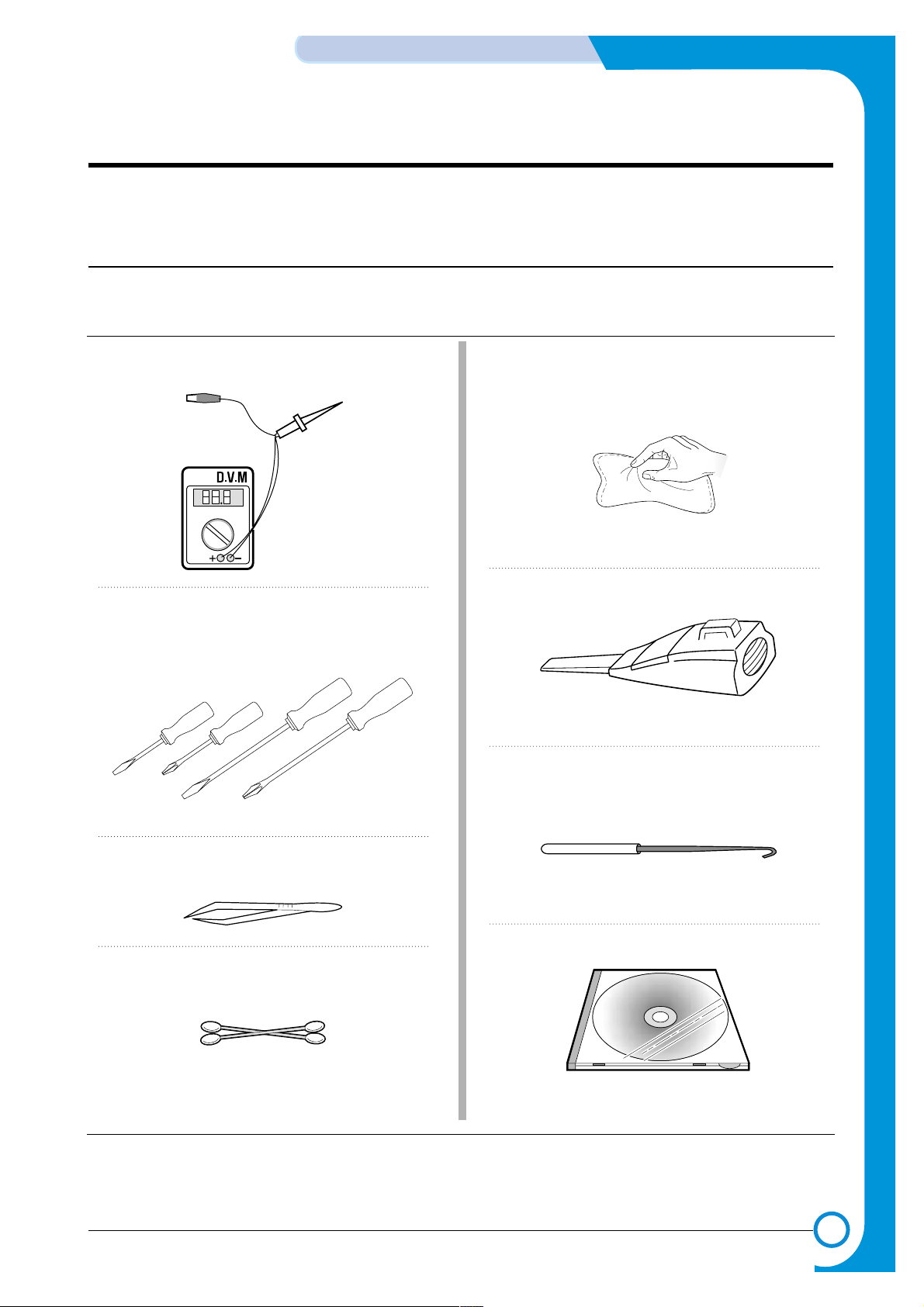
2.1 Tool for Troubleshooting
The following tools are recommended safe and easy troubleshooting as described in this service manual.
• DVM(Digital Volt Meter)
Standard : Indicates more than 3 digits.
• Driver
Standard : "-" type, "+" type (M3 long, M3 short, M2
long, M2 short).
• Tweezers
Standard : For general home use, small type.
• Cotton Swab
Standard : For general home use, for medical service.
• Cleaning Equipments
Standard : An IPA(Isopropyl Alcohol)dry wipe tissue or
a gentle neutral detergent and lint-free cloth.
• Vacuum Cleaner
• Spring Hook
Standard : For general use
• Software (Driver) installation CD ROM

2-2
Reference Information
Samsung Electronics
Service Manual
2.2 Acronyms and Abbreviations
The table in the below explains abbreviations used in this service manual.
The contents of this service manual are declared with abbreviations in many parts. Please refer to the
table.
ADC Analog-to-Digital-Conversion EPP Enhanced Parallel Port
AP Access Point F/W Firmware
AC Alternating Current FCF/FCT First Cassette Feeder/First Cassette Tray
ASIC Circuit
Application Specific Integrated FISO Front-In, Side-Out
ASSY Assembly FPOT First Print out Time
BIOS Basic Input Output System GDI Windows Graphic Device Interface
BLDC Motor
Brushless DC Motor GIF Graphic Interchange Format
CMOS Complementary Metal Oxide Semiconductor HBP Host Based Printing
CMYK Cyan, Magenta, Yellow, Black GND Ground
CN Connector HDD Hard Disk Drive
CON Connector HTML Hyper Text T ransfer Protocol
CPU Central Processing Unit HV High Voltage
CTD Sensor
Color T oner Density Sensor HVPS High V oltage Power Supply
dB Decibel I/F Interface
dBA A-Weighted decibel I/O Input and Output
dBm Decibel milliwatt lb Pound(s)
DC Direct Current IC Integrated Circuit
DCU Diagnostic Control Unit ICC International Color Consortium
DIMM Dual In-line Memory Module IDE Intelligent Drive Electronics or
Integrated Drive Electronics
DPI Dot Per Inch IEEE Institute of Electrical and
DRAM Dynamic Random Access Memory Electronics Engineers. Inc
DVM Digital Voltmeter IOT Image Output Terminal
(Color printer, Copier)
ECP Enhanced Capability Port IPA Isopropy Alcohol
ECU Engine Control Unit IPC Inter Process CommunicationEPP
Enhanced parallel Port
EEPROM Electronically Erasable IPM Images Per Minute
Programmable Read Only Memory
EMI Electro Magnetic Interference ITB Image Transfer Belt
EP Electro photographic RAM Random Access Memory
LAN local area network ROM Read Only Memory
LBP Laser Beam Printer SCF/SCT Second Cassette Feeder/Second
Cassette Tray

2-3
Samsung Electronics
Reference Information
Service Manual
LCD Liquid Crystal Display SMPS Switching Mode Power Supply
LED Light Emitting Diode SPGP Samsung Printer Graphic Processor
LSU Laser Scanning Unit SPL Samsung Printer Language
MB Megabyte Spool Simultaneous Peripheral Operation Online
MHz Megahertz SURF Surface Rapid Fusing
MPBF Mean Prints Between Failure SW Switch
MPF/MPT Multi Purpose Feeder/Multi Purpose Tray sync Synchronous or Synchronization
NIC Network Interface Card T1 ITB
NPC Network Printer Card T2 Transfer Roller
NVRAM Nonvolatile Random Access Memory TRC Toner Reproduction Curve
OPC Organic Photo Conductor PnP Universal Plug and Play
PBA Printed Board Assembly URL Uniform Resource Locator
TRC Toner Reproduction Curve USB Universal Serial Bus
PCL Printer Command Language , VCCI Voluntary Control Council for
Printer Control Language Interference Information
Technology Equipment
PCI Peripheral Component Interconnect by WECA Wireless Ethernet Compatibility
Intel 1992/6/22, is a local bus standard developed by Alliance
Intel and introduced in April, 1993 : A60, B60 Pins
PDF Portable Document Format Wi-Fi Wireless Fidelity
PDL Page Description Language
Ping Packet internet or Inter-Network Groper
PPD Postscript Printer Discription
PPM Page Per Minute
PS Post Script
PTL Pre-Transfer Lamp
PWM Pulse Width Moduration
Q'ty Quantity
2-4
Reference Information
Samsung Electronics
Service Manual
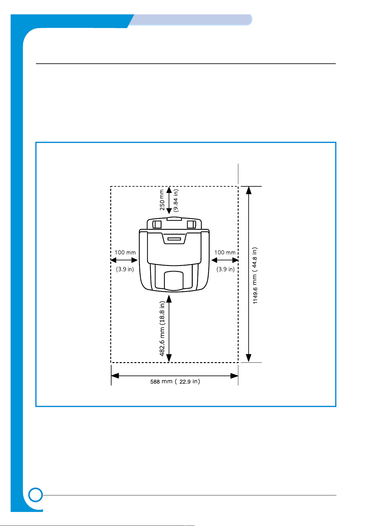
2.3 Select a location for the printer
• Leave enough room to open the printer trays, covers, and allow for proper ventilation. (see diagram
below)
• Provide the proper environment :
- A firm, level surface
- Away from the direct airflow of air conditioners, heaters, or ventilators
- Free of extreme fluctuations of temperature, sunlight, or humidity
- Clean, dry, and free of dust
2-5
Samsung Electronics
Reference Information
Service Manual
2.4 The Sample Pattern for the Test
The sample pattern shown in below is the standard pattern used in a factory.
The contents of the life span and the printing speed are measured with the pattern shown in below.
(The picture in the manual is 70% size of the actual A4 size.)
2.4.1 A4 5% Pattern
2-6
Reference Information
Samsung Electronics
Service Manual
2.4.2 A4 2% Pattern
2-7
Samsung Electronics
Reference Information
Service Manual
2.4.3 A4 IDC 5% Patten

2-8
Reference Information
Samsung Electronics
Service Manual
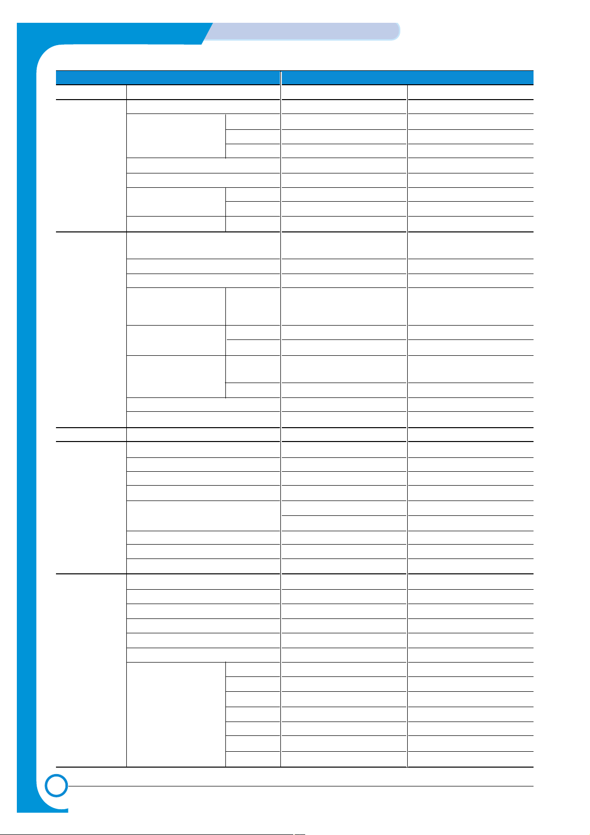
Specifications
Items SF-750 Series
Model Name SF-755P SF-750
Functions Fax,Copier,Printer,Scanner Fax,Copier
General Size (W*D*H) w/o Hand Set 383.7 * 416.8 * 334.9(mm) 383.7 * 416.8 * 334.9(mm)
Weight Without Toner Cartridge 11kg 11kg
With Toner Cartridge 14kg 14kg
LCD 16*2 Char 16*2 Char
Interface IEEE1284, USB 2.0 USB 2.0 : f/w Down Load
AMV(Average Month Volume)
Printing 1,000 1,000
Scan to Copy
1,000 1,000
or Scan to Fax
Duty cycle, Monthly Printing Up to 10,000 pages Up to 10,000 pages
ADF SCAN Up to 5,000 pages Up to 5,000 pages
Engine Life Up to 120,000 pages Up to 120,000 pages
Power Power Switch Y es Yes
Consumption Input Voltage
AC1 10V~127V , 220V ~ 240V AC1 10V~127V , 220V ~ 240V
Power Sleep Mode Energy Star Compliant Energy Star Compliant
**Noise Operating(ADF) Less than 52 dBA Less than 52 dBA
Standby Less than 39 dBA Less than 39 dBA
Printing Less than 50 dBA
Less than 50dBA
(Fax Rec., Memory Copy)
EMI Approval EMI Approval Class B Class B
PC Print Power Save Mode Y es (5/10/15/30/45min.off) Yes (5/10/15/30/45min.off)
Print Method Laser Laser
N/W I/f No No
*Speed (Eninge) Up to 16 PPM in A4 size,
Up to 17 PPM in Letter size -
Resolution Normal
Up to 600 x 600 DPI effective output
-
RET No Print Language GDI Toner Save Y es Yes(Text Mode)
Fpot Stand by Approx. 12 seconds -
Power Save Less than 42 seconds Printable Area 208 x 273 mm (Letter) Duplex Print
Manual (driver support provided)
-
3
3
3-1
Samsung Electronics
Service Manual
3. Specifications
Specfications are correct at the time of printing. Product specifications are subject to change without notice.
See below for product specifications.
* Speed will be affected by Operating System used, computing performance, application software, connect-
ing method, media type, media size and job complexity.
** Sound Pressure Level, ISO 7779
3-2
Specifications
Samsung Electronics
Service Manual
Items SF-750 Series
Model Name SF-755P SF-750
Scan Scan Method CIS, Color CIS, Color
* Scan Speed Gray Up to 72 sec (Second /scan) Color
Up to 20 sec 75 DPI (256 color)
-
Black&White Up to 25 sec -
Resolution(Optical)
Up to 1200 x 1200 DPI effective output
Halftone 256level Scan Width Max 216mm -
Effective 208mm -
Scan Length Max 400mm -
Copy * Speed Up to 16 PPM in A4 size, Up to 16 PPM in A4 size,
Up to 17 PPM in Letter size Up to 17 PPM in Letter size
Resolution 600x600dpi 600x600dpi
Halftone 256level 256level
Cop y Q u a l i t y S e l e c t i o n Text 5.5sec/Letter 5.5sec/Letter
or O r i g i n al Im a ge ty p e Photo 5.5sec/letter 5.5sec/letter
selection Mode
FCOT Power Save approx : 45sec approx : 45sec
Stand by approx : 15sec approx : 15sec
* Copy Speed SDMC Up to 16 PPM in A4 size, Up to 16 PPM in A4 size,
Up to 17 PPM in Letter size Up to 17 PPM in Letter size
MDMC 10cpm(Ltr) 10cpm(Ltr)
Zoom Range 50-200% 50-200%
Multi Copy 1~99 1~99
Telephone Handset No No
1-Touch Dial 40 Locations(20X2) 40 Locations(20X2)
Speed Dial 150 150
T AD No No
T AD I/F Yes Yes
Tone/Pulse Tone (DTMF) Tone (DTMF)
Pulse : setting in tech mode Pulse : setting in tech mode
Earth/Recall No No
SMS NO NO
External Phone Interface Y es Yes
Fax Compatibility ITU-T G3 ITU-T G3
Communication System PSTN/PABX PSTN/PABX
Modem Speed 33.6Kbps 33.6Kbps
TX Speed approx. 3 sec approx. 3 sec
Compression MH/MR/MMR/JBIG MH/MR/MMR/JBIG
ECM Yes Yes
Resolution Std
Up to 203 x 98 DPI effective output Up to 203 x 98 DPI effective output
Fine
Up to 203 x 196 DPI effective output Up to 203 x 196 DPI effective output
S.Fine
Up to 300 x 300 DPI effective output Up to 300 x 300 DPI effective output
Photo
Up to 200 x 200 DPI effective output Up to 200 x 200 DPI effective output
Std Up to 1.5 sec Up to 1.5 sec
Fine Up to 3 sec Up to 3 sec
S.Fine Up to 4.2 sec Up to 4.2 sec

3-3
Samsung Electronics
Specifications
Service Manual
Items SF-750 Series
Model Name SF-755P SF-750
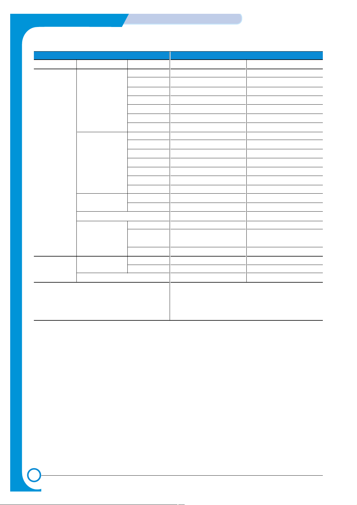
Fax Halftone 256level 256level
(Continued) Memory Capacity
Total memory: 32MB( Fax: 5MB) Total memory: 32MB( Fax: 5MB)
Optional Memory
No No
Broadcasting Yes Y es
Delay TX Yes Y es
Memory RX Yes Y es
Functions Voice Request No No
TTI Yes Yes
RTI Yes Yes
Polling Rx Polling Rx Polling
Security Receive
Yes Yes
Flash No No
Auto Reduction Y es Yes
"F/W Upgrade Y es Yes
from Remote"
Memory B/U Y es(Max. 72Hours) Y es(Max. 72Hours)
Paper Handling
Casstte Type Cassette Cassette
Input Capacity 250 Sheets/20lb 250 Sheets/20lb
Optional Cassette
250 Sheets/20Ib 250 Sheets/20Ib
Output Capacity
Max. 150 Sheets/20lb Max. 150 Sheets/20lb
Output Control Face down Face down
Bypass 1sh 1sh
Media Size for For Fax and Copy: A4,Letter, For Fax and Copy: A4,Letter,
Main Tray Legal For PC Print : A4,Letter, Legal For P C Prin t : A4 , L e t t e r,
Legal. Folio, Executive, B5 Legal. Folio, Executive, B5"
Media Size for Envelope6 3/4, 7 3/4,#9, Envelope6 3/4, 7 3/4,#9,
Bypass #10,DL,C5,B5 #10,DL,C5,B5
Media Weight Auto : 16 ~ 28 Ib Auto : 16 ~ 28 Ib
Bypass: 16 ~ 43 Ib Bypass: 16 ~ 43 Ib
ADF Input Capacity Max. 50 Sheets Max. 50 Sheets
Media Weight 12.5lb ~ 28lb, 32lb(1 sheet) 12.5lb ~ 28lb, 32lb(1 sheet)
* Copy or Scan speed will be affected by Operating System used, computing performance, application software,
connecting method, media type, media size and job complexity.
3-4
Specifications
Samsung Electronics
Service Manual
Items SF-750 Series
Model Name SF-755P SF-750
Software Compatibility DOS No No
Win 3.x No No
Win 95 Yes No
Win 98&WinME Yes No
Win NT 4.0 Yes No
Win 2000 Y es No
Win XP Yes No
Driver GDI Printer SPL No
TWAIN Yes No
FaxRCP Y es No
Mac Printer Y es No
Linux Printer Yes No
Linux Scanner Yes No
PC-FAX No No
M/S Certification WHQL Y es (WinXP Printer driver only) -
WIA No No
Bundle S/W SmarThru 3 Media CD-ROM Yes -
Manual Standalone Fax: Book Standalone Fax: Book
MFP: CD
Diskette No No
Consumables Life Initial Up to 3,000 Pages Up to 3,000 Pages
Running Up to 3,000 Pages Up to 3,000 Pages
Toner Sensor (Software) Yes(Dot Counter) Yes(Dot Counter)
Periodic Replacing Parts ADF Rubber Pad : Up to 20,000 Pages
Paper Feeding Roller : Up to 60,000 Pages
Transfer Roller :Up to 60,000 Pages
Fuser Unit : Up to 60,000 Pages
4
4
4-1
Samsung Electronics
SUMMARY OF PRODUCT
Service Manual
4. Summary of Product
This chapter describes the functions and operating principal of the main component.
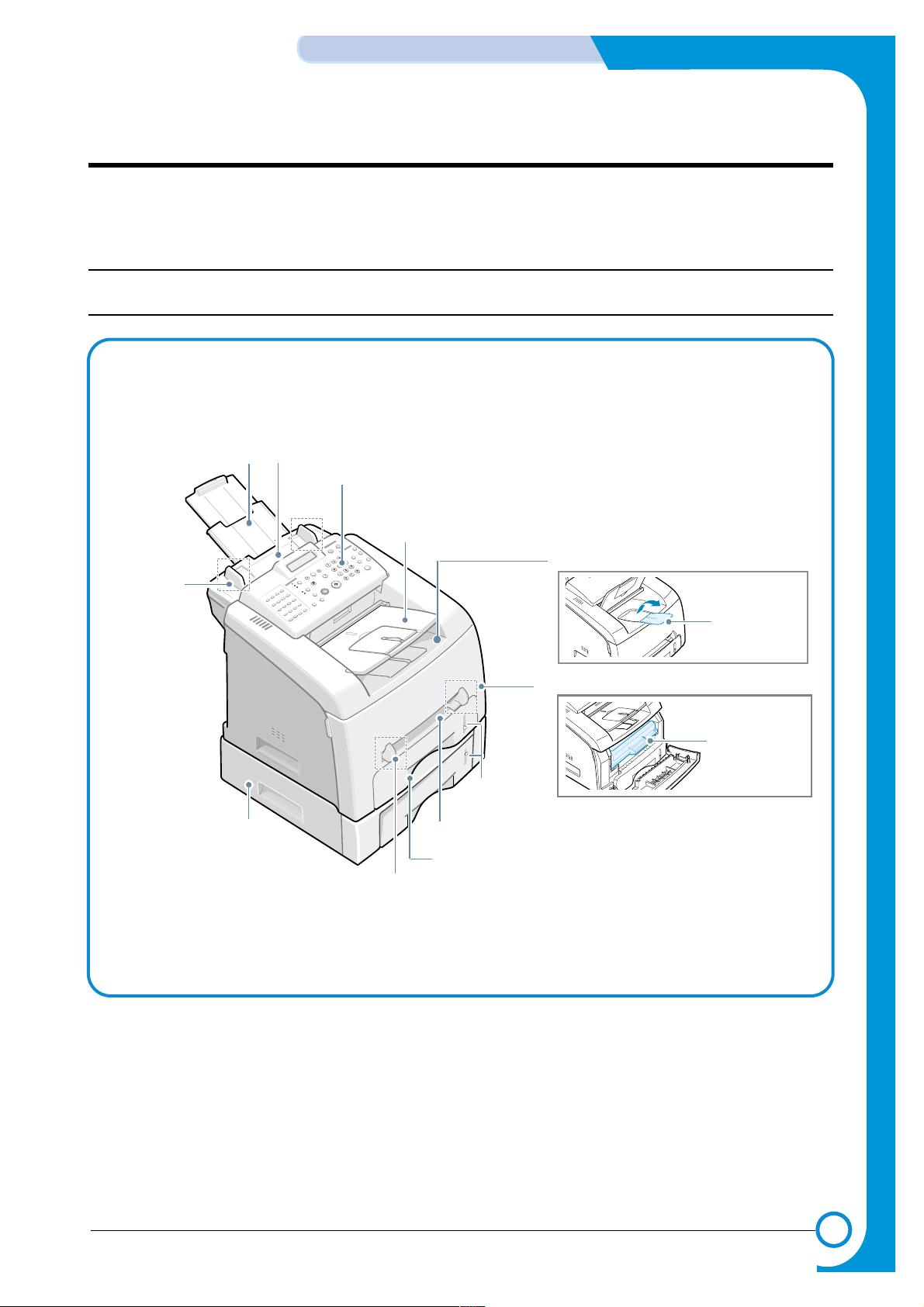
4.1 Printer Components
4.1.1 Front View
Control Panel
Front Cover
Paper Tray(Tray1)
Front Output Tray
(Face down)
Document Input
Support
Automatic
Document Feeder
Toner Cartridge
Paper
Extension
Manual Feeder
Manual Feeder
Guides
Document
Guides
Document
Output Tray
Optional Paper
Tray(Tray2)
Paper Level
Indicator
4-2
SUMMARY OF PRODUCT
Samsung Electronics
Service Manual
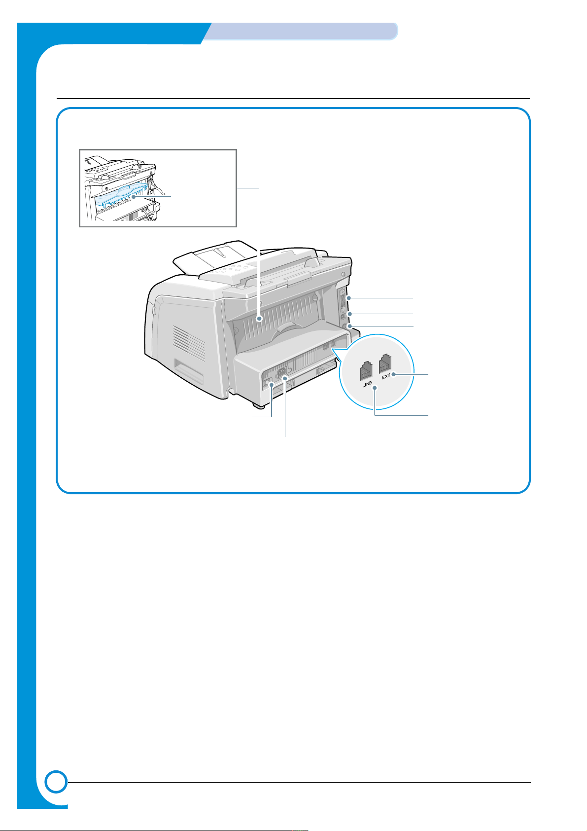
4.1.2 Rear View
Line Jack EXT.Jack
Power Switch
USB Connector
AC Power Cord
Connector
EXT Jack
*
Line Jack
*
If your country has a different
telephone connection system,
this socket may be blocked.
Rear Output
Slot (Face up)
Tray 2 Cable
Connector
Parallel Connector
4-3
Samsung Electronics
SUMMARY OF PRODUCT
Service Manual
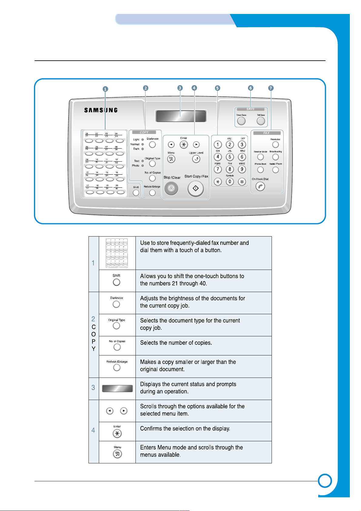
4.1.3 Control Panel
< SF-750/755P >

4-4
SUMMARY OF PRODUCT
Samsung Electronics
Service Manual

4-5
Samsung Electronics
SUMMARY OF PRODUCT
Service Manual
4.2 Overview of System
SF-750/SF-755P can be divided into the following main constituent parts: Main Controller, Operator’s Panel, PC
Interface, Scanner, Line Interface and Power Supply. The Main Controller uses the SPGPm processor. The
Operator’s panel; (OPE) has its own MICOM which communicates serially with a UART built into the SPGPm
processor. The Scanner uses the CIP4e processor to control the CIS. The Line Interface is an FM336 integrated
with the Main Board which communicates with the LIU at speeds up to 33.6Kbps.
The Power Supply has both the SMPS and HVPS integrated on one PBA. Because of the structure and layout of
the set many of the sensors are also located on the SMPS/HVPS board. Signals from these sensors are passed
to the main board for processing.
4.2.1 Main Control Part.
The Main Controller of the SF-750/755P consists of two ASICs (CPU, Image Processor), Scanner, Fax Modem
and Print sections. Bus Control, I/O Handling, Engine motor drivers and the PC Interface function is controlled by
the CPU (SPGPm).
The Image Processor (CIP4e) controls the ADF motor, CIS scanner and is responsible for image manipulation and
compression.
4.2.2 Line Interface Part
This part connects the set with the PSTN. The main functions of this section are Line Interface, Line Monitoring,
and connection to an external phone or TAD using the built in EXT connector..
4.2.3 Print Engine.
The Print Engine consists of the following sections: Frame, Paper Feed, Image Transfer , Imaging Unit, T oner
Cartridge, Fuser, High Voltage Supply and Scanner. The set uses an Electro Photographic process using the LSU
to develop a latent image on the OPC drum. The T oner process is a single part diamagnetic process. Copy and
Transfer processes use a CIS Module.
4.2.4 Scan Part
The scanner is designed around a 600dpi CIS module. The CIS scanning width is maximum 216mm, effective
width is 208mm..
4.2.5 Summary of Main Unit
- Main Board
This is an integral unit having the Engine and Video control on a single PBA. It controls the Electrophotographic
Process to take the image from the PC Interface and generate the Video Data for the LSU. It also manages the
transfer of that image onto paper and the fusing of the image. The main PBA unit consists of the following circuits:
Motor (Paper Feed and Exit) Driver, the Clutch driver , Pre-transfer Lamp Driver, the Fuser Driver and the Fan
Driver. The signals from the Paper Feed Sensor, the Paper Empty Sensor , MP sensor and Exit Sensor are input to
the Main Board from the SMPS/HVPS PBA.

4-6
SUMMARY OF PRODUCT
Samsung Electronics
Service Manual
- SMPS Board & HVPS Board
These are integrated into a singe PBA. The Power Supply uses the 110VAC/220VAC supply voltage to generate
the DC Voltages used by the system. The SMPS has 3 output channels (+5V, +12V , +24V, +24VS) and supplies
the Main Board and the OPE Board.
The HVPS creates the high voltages (THV/MHV/Supply/Dev) used for the electrophotographic process. The high
voltage is created from the 24VS line from the SMPS. High Voltage output is supplied to the Toner , the OPC
Cartridge and the T ransfer Roller .
- OPE Board
The Operation Panel is driven by its own internal program using the OPE MICOM chip separate from the Main
Board processor. Data is transferred using the UART Port in the Main Controller serially. This unit
consists of the MICOM, the Key Pad Matrix and the LCD.
- Toner Cartridge
The Toner Cartridge consists of integrated Exposure and Developer units. The Exposure Unit consists of the OPC
Drum and the Charge Roller, and the Developer Unit consists of the toner particles and its tank, the Supply Roller
and the Developer Roller .
- LSU (Laser Scanner Unit)
This is the core of the laser printer. It converts the video data received from the computer into an electrostatic
latent image on the surface of the OPC drum. This is achieved by controlling the laser beam and exposing the surface of the OPC drum to the laser light. A rotating polygon mirror reflects the laser light onto the OPC and each
side of the mirror is one scan line. The OPC drum turns as the paper feeds to scan the image down the page.
The /HSYNC signal is created when the laser beam from LSU reaches the end of the polygon mirror and this signal is sent to the controller. The controller detects the /HSYNC signal to adjust the vertical line of the image on
paper. In other words after the /HSYNC signal is detected the image data is sent to the LSU to adjust the left margin on the paper .
- Toner T ransfer
Toner is transferred from the OPC drum onto the paper using a PTL (Pre-transfer Lamp) and a transfer roller. The
PTL shines light onto the OPC, this reduces the electrical charge on the surface of the OPC
surface and improves the efficiency of the transfer .
The transfer roller transfers toner from the OPC drum to the paper.
Life span: Print over 100,000 sheets (at 15~30ºC)
- Fuser
This consists of a heat lamp, heat roller, pressure roller, thermistor and thermostat. By use of heat and pressure
toner is caused to melt and adhere to the paper surface in order to complete the printing process.

4-7
Samsung Electronics
SUMMARY OF PRODUCT
Service Manual
4.3 System Layout
4.3.1 Feeding section
There is a universal cassette which automatically loads paper and the manual feed which supplies paper
single sheet at a time. The cassette has a friction pad which separates paper to ensure single sheet
feeding, and it has a sensor, which checks when the paper tray is empty.
- Feeding Method: Universal Cassette Type
- Feeding Standard: Center Loading
- Feeding Capacity: Cassette-250 sheets (75g/m2, 20lb paper standard)
Manual 1 sheet (Paper, OHP, Envelop, etc.)
- Paper detecting sensor: Photo sensor
- Paper size sensor: None
4.3.2 Transfer Ass’y
This consists of the PTL (pre-transfer lamp) and the Transfer Roller. The PTL shines a light onto the OPC
drum. This lowers the charge on the drum’s surface and improves transfer efficiency.
The transfer roller transfers toner from the OPC drum surface to the paper.
- Life expectancy: Over 60,000 sheets (at 15~30°C)
4.3.3 Driver Ass’y
- Gear driven power unit. The motor supplies power to the paper feed unit, the fuser unit, and the toner
cartridge.
4.3.4 Fixing Part(Fuser)
- The fuser consists of the Heat Lamp, Heat Roller, Pressure Roller, Thermistor, and Thermostat. It fixes
toner to the paper using pressure and heat to complete the printing job.
4.3.4.1 Temperature-Intercepting Device (Thermostat)
The thermostat is a temperature sensing device, which cuts off the power to the heat lamp to prevent
overheating fire when the heat lamp or heat roller overheats.
4.3.4.2 Temperature Detecting Sensor (Thermistor)
The Thermistor detects the surface temperature of the heat roller, this information is sent to the main
processor which uses this information to regulate the temperature of the heat roller.
4.3.4.3 Heat Roller
The surface of the Heat Roller is heated by the Heat Lamp. As the paper passes between the Heat and
Pressure rollers the toner is melted and fixed permanently to the paper. The surface of the roller is coated
with Teflon. This ensures that toner does not adhere to the roller surface.
4.3.4.4 Pressure roller
The Pressure Roller mounted under the heat roller, it is made of a silicon resin, and the surface of the roller
is coated with Teflon. This ensures that toner does not adhere to the roller surface.

4-8
SUMMARY OF PRODUCT
Samsung Electronics
Service Manual
4.3.4.5 Safety Features
• To prevent overheating
- 1st protection device: Hardware cuts off when overheated
- 2nd protection device: Software cuts off when overheated
- 3rd protection device: Thermostat cuts off mains power to the lamp.
• Safety device
- Fuser power is cut off when the front cover is opened
- LSU power is cut off when the front cover is opened
- The temperature of the fuser cover's surface is maintained at less than 80ºC to protect the user and a
caution label is attached where the customer can see it easily when the rear cover is opened.
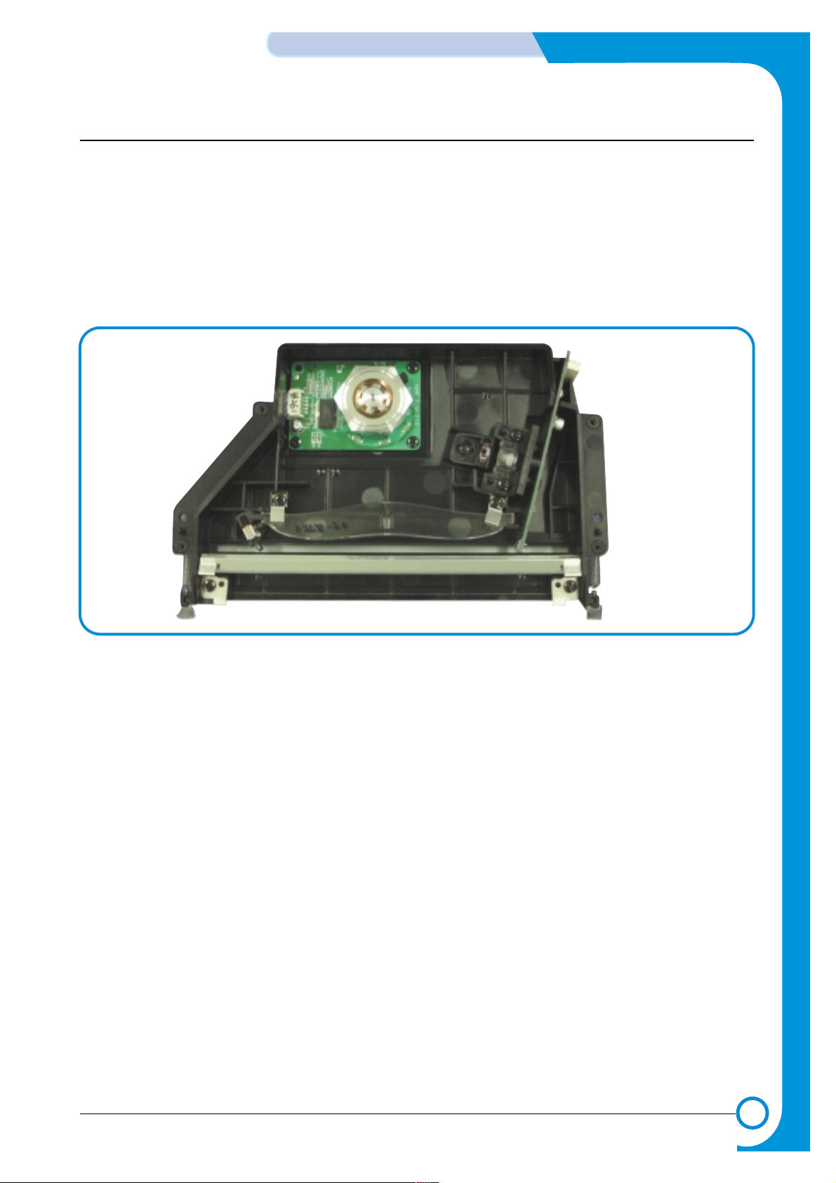
4.3.5 Scanner
• Scan Image Controller
1.Minimum Scan Line Time : 1.25ms
2.Scan Resolution : Color : Max. 600DPI
3.Scan Width : 208mm
4.Function
- White Shading Correction
- Gamma Correction
- CIS Interface
- 256 Gray Scale
• CIS Driver Circuit
- CIS Max Frequency : 2.5MHz
- CIS Line Time : 1.25ms/Line(at Fax Mode)
- White Data Output Voltage : Max 1.2V
• Tx Driver Circuit
- Tx Motor Speed : Max 2200pps
- Motor Driver : TEA3718
- Used Volt : 24V DC
4-9
Samsung Electronics
SUMMARY OF PRODUCT
Service Manual
4.3.6 LSU (Laser Scanner Unit)
This is the core of the laser printer. It converts the video data received from the computer into an electrostatic
latent image on the surface of the OPC drum. This is achieved by controlling the laser beam and exposing the
surface of the OPC drum to the laser light. A rotating polygon mirror reflects the laser light onto the OPC and each
side of the mirror is one scan line. The OPC drum turns as the paper feeds to scan the image down the page.
The /HSYNC signal is created when the laser beam from LSU reaches the end of the polygon mirror and this
signal is sent to the controller. The controller detects the /HSYNC signal to adjust the vertical line of the image on
paper. In other words after the /HSYNC signal is detected the image data is sent to the LSU to adjust the left margin
on the paper.
4-10
SUMMARY OF PRODUCT
Samsung Electronics
Service Manual
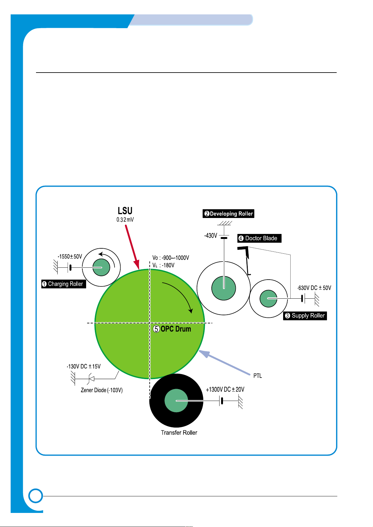
4.3.7 Toner Cartridge
The toner cartridge is an integral unit containing the OPC unit and toner unit. The OPC unit consists of the
OPC drum and charging roller, and the toner cartridge unit consists of the toner, supply roller, developing
roller, and blade (Doctor blade)
- Developing Method: Non magnetic 1 element contacting method
- Toner: Non magnetic 1 element shatter type toner
- The life span of toner: 3,000 sheets (IDC Pattern/A4 standard)
- Toner remaining amount detecting sensor: Yes
- OPC Cleaning: Electrostatic process
- Management of waste toner: Collect the toner using a Cleaning Blade
- OPC Drum protecting Shutter: Yes
- Classifying device for toner cartridge: ID is classified by interruption of the frame channel
4-11
Samsung Electronics
SUMMARY OF PRODUCT
Service Manual
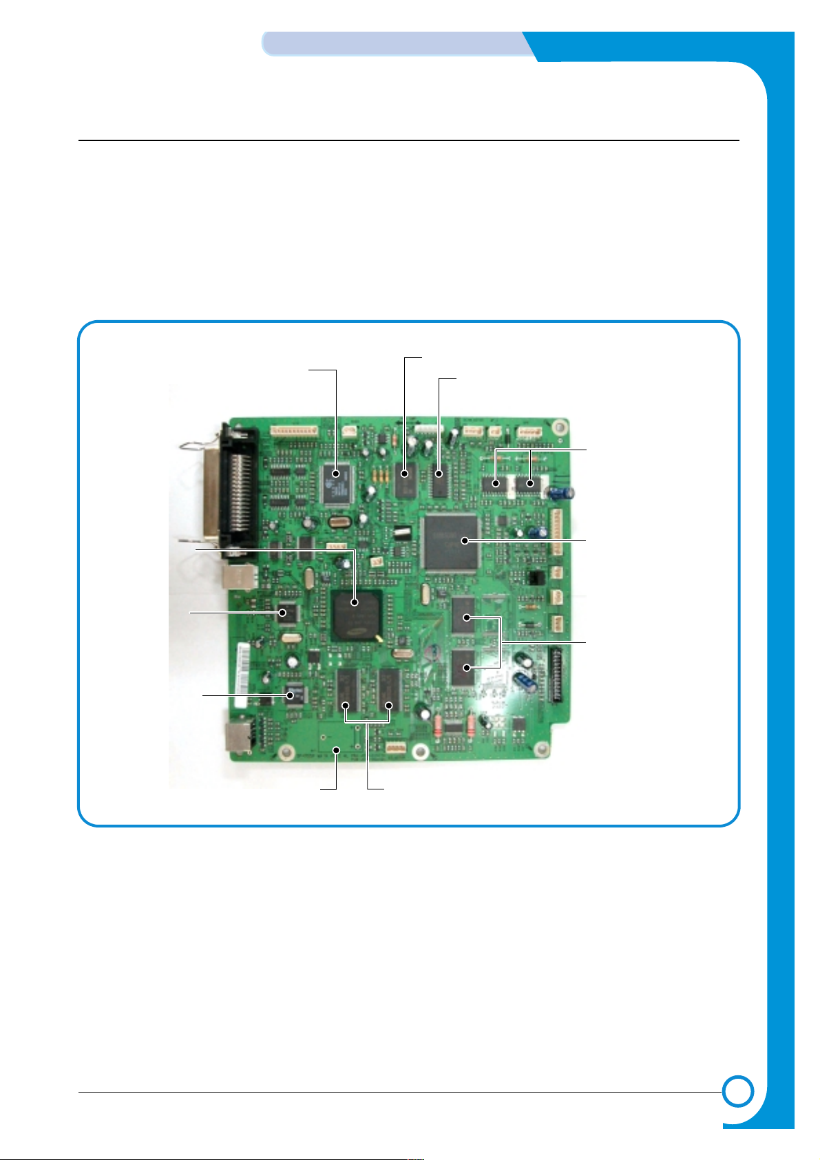
4.4 Main PBA(SPL Model)
The Engine Board and Controller Board have been integrated into a single PBA. This consists of the CPU,
printer scanner and line control functions. The CPU functions as the bus controller, I/O handler, motor driver
and PC inter-face. The main board sends the Current Image Video data to the LSU and manages the
Electrophotographic printing process. Circuits on the PBA drive include the main motor (paper feed,
cartridge, fuser), clutch driver, pre-transfer lamp driver, heat-lamp driver, CIS driver, scan motor driver,
modem and fan driver.
The signals from the paper feed jam sensor and paper empty sensor are inputted to the main board from
the power supply PBA..
MODEM
(FM336R6719-12)
SRAM(K6R1016VID)
A/D CONVERTER
(AFE-CIP4)
MOTOR DRIVER
(TEA3718SFP)
IMAGE PROCESSOR
(CIP4E)
BATTERY(3.6V)
FPGA ASIC
(EX64-FTQ64)
GRAPHIC
PROCESSOR ASIC
(SPGPM)
USB
(NET2270)
DRAM(K4S281632D)
FLASH MEMORY
(29LV800)

4-12
SUMMARY OF PRODUCT
Samsung Electronics
Service Manual
4.4.1 ASIC (SPG Pm)
The SPG Pm (32Bit RISC Processor), is the main processor in overall charge of the set’s operation. It is
controlled by the system program held in flash memory.
•Main function block
• 272 Pin PBGA Package
• 120MHz Core, 60MHz Bus Operation
• 326bit RISC Processor, ARM946ES Core
• USB 2.0 Interface
• Power Operation : 1.8V(Core), 3.3V(IO)
4.4.2 Flash Memory
This stores the system program. Firmware upgrade is achieved by downloading from the new image using the PC
Interface.
• Capacity : 2.0 M Byte
• Access T ime : 70 nsec
4.4.3 SDRAM
This is used as a buffer, system working memory area, etc. while printing and scanning. This memory is also used to
store faxes waiting to be sent or waiting to be printed.
• Operating Freguency : 60 MHz
 Loading...