

Samsung SF6500, SF6600 Service manual
FACSIMILE
SF6500/SF6600
CONTENTS
1. Precautions
2. Specification
3. Installation
4. Theory of Operation
5. Circuit Description
6. Disassembly and Reassembly
7. Maintenance & Troubleshooting
8. Electrical Parts List
9. PCB Diagrams
10. Block Diagram
11. Wiring Diagram
12. Schematic Diagrams
FACSIMILE
SERVICE
Manual

Samsung Electronics Co.,Ltd. June. 1998
Printed in Korea.
JC68-61013A
ELECTRONICS

Samsung Electronics 1-1
1. Precautions
Follow these safety, ESD, and servicing precautions to prevent personal injury and equipment damage.
1-1 Safety Precautions
1. Be sure that all built-in protective devices are in
place. Restore any missing protective shields.
2. Make sure there are no cabinet openings
through which people- particularly childrenmight insert fingers or objects and contact
dangerous voltages.
3. When re-installing chassis and assemblies, be
sure to restore all protective devices, including
control knobs and compartment covers.
4. Design Alteration Warning:
Never alter or add to the mechanical or electrical
design of this equipment, such as auxiliary
connectors, etc. Such alterations and
modifications will void the manufacturer's
warranty.
5. Components, parts, and wiring that appear to
have overheated or are otherwise damaged
should be replaced with parts which meet the
original specifications. Always determine the
cause of damage or overheating, and correct any
potential hazards.
6. Observe the original lead dress, especially near
sharp edges, AC, and high voltage power
supplies. Always inspect for pinched, out-ofplace, or frayed wiring. Do not change the
spacing between components and the printed
circuit board.
7. Product Safety Notice:
Some electrical and mechanical parts have
special safety-related characteristics which might
not be obvious from visual inspection. These
safety features and the protection they provide
could be lost if a replacement component differs
from the original. This holds true, even though
the replacement may be rated for higher voltage,
wattage, etc.
Components critical for safety are indicated in
the parts list with symbols . Use only
replacement components that have the same
ratings, especially for flame resistance and
dielectric specifications. A replacement part that
does not have the same safety characteristics as
the original may create shock, fire, or other
safety hazards.
Laser statement (Laserturvallisuus)
WARNING NEVER OPERATE AND SERVICE THE
FAX WITH PROTECTIVE COVER
REMOVED FROM LASER/SCANNER
ASSEMBLY. THE REFLECTED BEAM,
ALTHOUGH INVISIBLE, CAN DAMAGE
YOUR EYES.
Class 1 laser product
Product laser de la premi•re classe
Laser beam wavelength: 780nm
Longueur d'ondes de rayon laser: 780nm
Laser beam power: 0.18mW +/-0.009mW
Puissance de rayon laser: 0.18mW +/-0.009mW

Samsung Electronics
Precautions
1-2
1-2 ESD Precautions
Certain semiconductor devices can be easily
damaged by static electricity. Such components are
commonly called "Electrostatically Sensitive (ES)
Devices", or ESDs. Examples of typical ESDs are:
integrated circuits, some field effect transistors, and
semiconductor "chip" components.
The techniques outlined below should be followed
to help reduce the incidence of component damage
caused by static electricity.
CAUTION: Be sure no power is applied to the
chassis or circuit, and observe all other safety
precautions.
1. Immediately before handling a semiconductor
component or semiconductor-equipped
assembly, drain off any electrostatic charge on
your body by touching a known earth ground.
Alternatively, employ a commercially available
wrist strap device, which should be removed for
your personal safety reasons prior to applying power
to the unit under test.
2. After removing an electrical assembly equipped
with ESDs, place the assembly on a conductive
surface, such as aluminum or copper foil, or
conductive foam, to prevent electrostatic charge
buildup in the vicinity of the assembly.
3. Use only a grounded tip soldering iron to solder
or desolder ESDs.
4. Use only an "anti-static" solder removal device.
Some solder removal devices not classified as
"anti-static" can generate electrical charges
sufficient to damage ESDs.
5. Do not use Freon-propelled chemicals. When
sprayed, these can generate electrical charges
sufficient to damage ESDs.
6. Do not remove a replacement ESD from its
protective packaging until immediately before
installing it. Most replacement ESDs are
packaged with all leads shorted together by
conductive foam, aluminum foil, or a
comparable conductive material.
7. Immediately before removing the protective
shorting material from the leads of a
replacement ESD, touch the protective material
to the chassis or circuit assembly into which the
device will be installed.
8. Maintain continuous electrical contact between
the ESD and the assembly into which it will be
installed, until completely plugged or soldered
into the circuit.
9. Minimize bodily motions when handling
unpackaged replacement ESDs. Normal
motions, such as the brushing together of
clothing fabric and lifting one's foot from a
carpeted floor, can generate static electricity
sufficient to damage an ESD.
1. Exercise caution when replacing a Lithium
battery. There could be a danger of explosion
and subsequent operator injury and/or
equipment damage if incorrectly installed.
2. Be sure to replace the battery with the same or
equivalent type recommended by the
manufacturer.
3. Lithium batteries contain toxic substances and
should not be opened, crushed, or burned for
disposal.
1-3 Lithium Battery Precautions

Samsung Electronics 2-1
2. Specifications
2-1 Basic Features
Machine type : Desk Top
Applicable line : Public Switched Telephone Network (PSTN) or behind PABX
Compatibility : CCITT Group 3, ECM
Data coding : MH/MR/MMR
Modem speed : 33600/28800/14400/12000/9600/7200/4800/2400 bps
Transmission speed : Approx. 2.6 sec. (V.34 ECM : 33600 bps)
Effective scanning width : 8.3 inches (210 mm)
Effective printing width : 8.2 inches (208 mm)
Scanning method : Sheet-fed scanning using a Contact Image Sensor (CIS)
Memory : 4 MByte
Halftone : 64 levels
Printing speed : 6 PPM (Letter size)
Automatic document feeder : 30 pages
Phone : Built-in handset
One-touch dial : 20 locations
LCD : 16 characters X 2 lines
Dimension (H X W X D) : 9.8 X 14.3 X 17.5 inches (249 X 363 X 446 mm)
(trays and optional second cassette excluded)
Weight : Approx. 33.1 lb (15 kg) (fully equipped)
Approx. 22 lb (10 kg) (cartridge and recording paper excluded)
Power : 220V AC, 50/60 Hz
2-2 Technical Parameters
SCANNER
Scanning Method : Sheet-fed scanning by CIS and step feeding of the document by a
stepping motor
Resolution
Horizontal : 11.8 lines/mm (300 dpi)
Vertical : STANDARD : 3.85 lines/mm (98 Lpi)
FINE : 7.7 lines/mm (196 Lpi)
11.8 lines/mm (300 Lpi)
SUPER FINE : 15.4 lines/mm (392 Lpi)
Photo scale : 64 shades
Specification
2-2 Samsung Electronics
Scanning period : STANDARD : 5 ms/line
FINE : 2.5 ms/line
SUPER FINE : 2.5 ms/line
Document size
Width : 5.8 to 8.5 inches (148 to 216 mm)
Length :
Single page : 5 to 14 inches (128 to 356 mm)
Multi page : 5 to 11.7 inches (128 to 297 mm)
Manual assistance : infinite
Weight
single page : 12.5 Ib. ~ 32 Ib. (Thickness 0.07 ~ 0.15 mm)
Multi page : 12.5 Ib. ~ 24 Ib. (Thickness 0.07 ~ 0.15 mm)
Automatic document feeder (ADF) 30 sheets (Letter size/A4 size)
Class 1-5 : 10 sheets
Class 1-3 : 20 sheets
Thickness of document according to each class (Letter size/A4 size)
Scanning position
Top edge : 2 mm 2 mm (0.079 0.079 inch)
Bottom edge : 0 mm 2.5 mm (0 0.098 inch)
PRINTER
Recording method : Electrostatic image recording with LSU array
Printing speed : 6 pages (Letter size)/minute recording density
Horizontal : 11.8 lines/mm (300 dpi)
Vertical : 11.8 lines/mm (300 lpi)
Recording paper size : A4 : 8.3 × 11.7 inches (210 × 297 mm)
Letter : 8.5 × 11 inches (216 × 279 mm)
Legal : 8.5 ×14 inches (216 × 356 mm)
Weight : 16 ~ 24 Ibs (60 ~ 90 g/m2)
Thickness : 0.08 ~ 0.12 mm
Recording paper cassette
Basic cassette : 250 sheets (Letter size/A4 size)
Reference weight : 75 g/m2(20 Ibs)
CLASS THICKNESS WEIGHT (U.S. POUND)
1 0.075 mm 12.5 Ib
2 0.10 mm 20.0 Ib ADF: 30 sheets
3 0.12 mm 24.0 Ib ADF: 10 sheets
4 0.13 mm 28.0 Ib
5 0.15 mm 32.0 Ib
Specification
Samsung Electronics 2-3
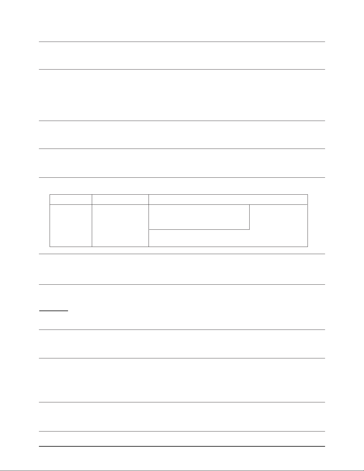
Effective recording area
First sheet copying time : Less than 30 seconds
Warm up time : Less than 30 seconds (at ambient temperature of 25 oC/77oF)
Recording paper stack
Type : Face down stack
Capacity : 100 sheets
Reference weight : 75 g/m2(20 Ibs)
Printing density and uniformity
Density : Greater than 1.0 O.D (Optical Density)
Uniformity : Less than 0.3 O.D
MODEM
Modulation
Group 3/ECM : CCITT V.34
CCITT V.17
CCITT V.29 V.27ter
Binary signal : CCITT V.21 T.30
Tonal signal : CCITT T.30
SOUND
Key click : Frequency 1.6 kHz, Duration 30 msec.
Alarm : Frequency 1.6 kHz, Duration 2 msec.
Transmission completion : Normal 1 sec./Error 1 sec.
Operator call : 15 sec. (1.28 sec. On/1.28 sec. OFF)
4 mm 4 mm
3 mm
EFFECTIVE RECORDING AREA
Top
Bottom
3 mm

Specification
2-4
POWER SUPPLY
Input voltage : 220V AC, 50/60Hz
Power consumption
Standby : 13 watts
Copy : 170 W (typical)
580 W (max.)
High voltage power supply
Input : 24 Vdc, 1.0 A
Output : 4.0 kVdc at 100 Mohm (Transfer Voltage)
-1.10 kVdc at 40 Mohm (Charge Voltage)
-900 Vdc at 100 Mohm (Retransfer Voltage)
-400 Vdc at 40 Mohm (Bias Voltage)
2-3 Second Paper Cassette (Option)
GENERAL
Dimension (HWD :) 4.2 x 14.1 x 16.1 inches (107 x 360 x 410 mm)
Weight : approx. 11 lb (5 kg)
RECORDING PAPER SIZE
Size : Letter size : 8.5 x 11 inches (216 x 279 mm)
A4 size : 8.3 x 11.7 inches (210 x 297 mm)
Legal size : 8.5 x 14 inches (216 x 356 mm)
Weight : 16 ~ 24 lbs (60 ~ 90 g/m2)
Thickness : 0.08 ~ 0.12 mm
CASSETTE
Basic : 250 sheets (Letter/Legal/A4 size)
Reference weight : 75 g/m
2
REPLACEMENT CYCLE
Pickup roller : Cleaning: 1 year / Replacement : 3 ~ 5 years or 50,000 sheets
Feed roller : Cleaning: 1 year / Replacement : 3 ~ 5 years or 50,000 sheets
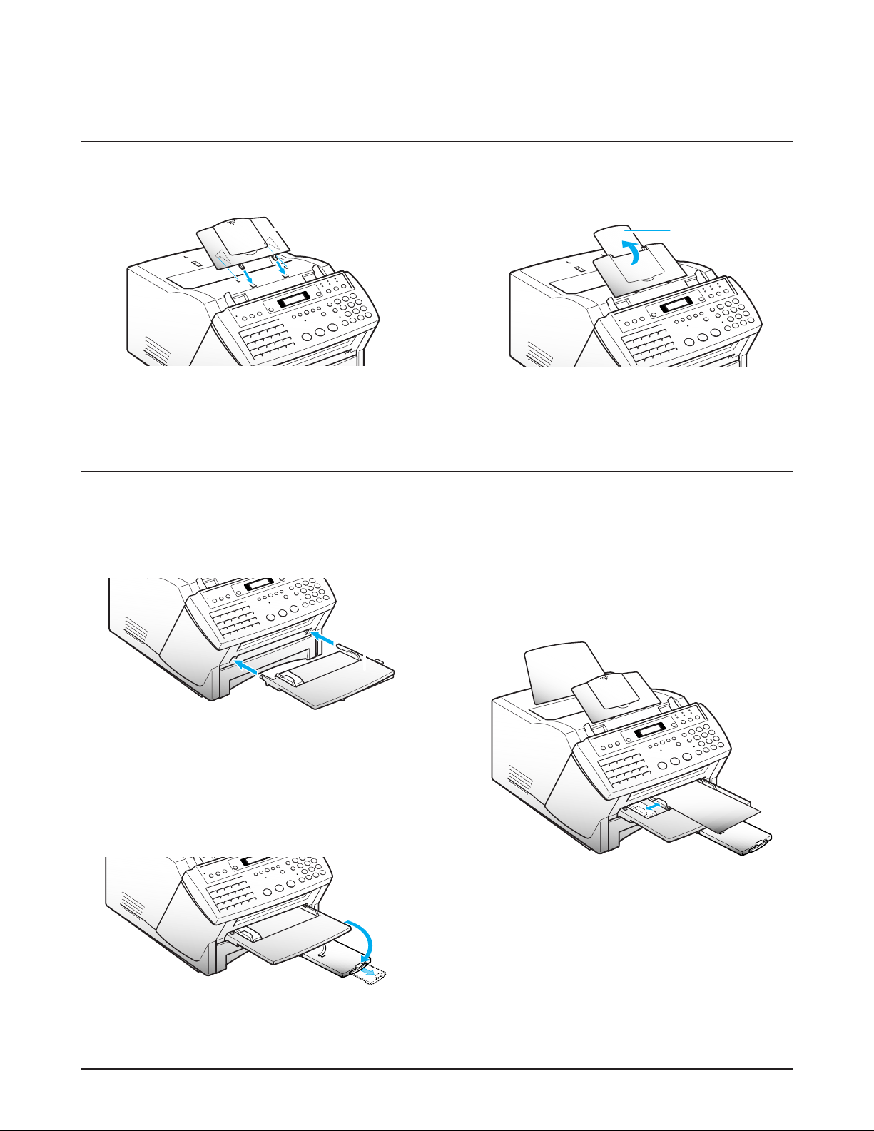
1. Insert two tabs on the document exit tray into the
slots on the front of your machine.
2. Fold out the extender, if necessary.
The extender can be folded out up to 3 steps.
This tray is also used to feed envelopes or recording
paper manually to print out PC job if your machine
is upgraded to use with PC.
Adjust the guides to match the width of the paper.
Document
exit tray
A4 B5
A5
A6
Ltr
3. Installation
3-1 Document Tray
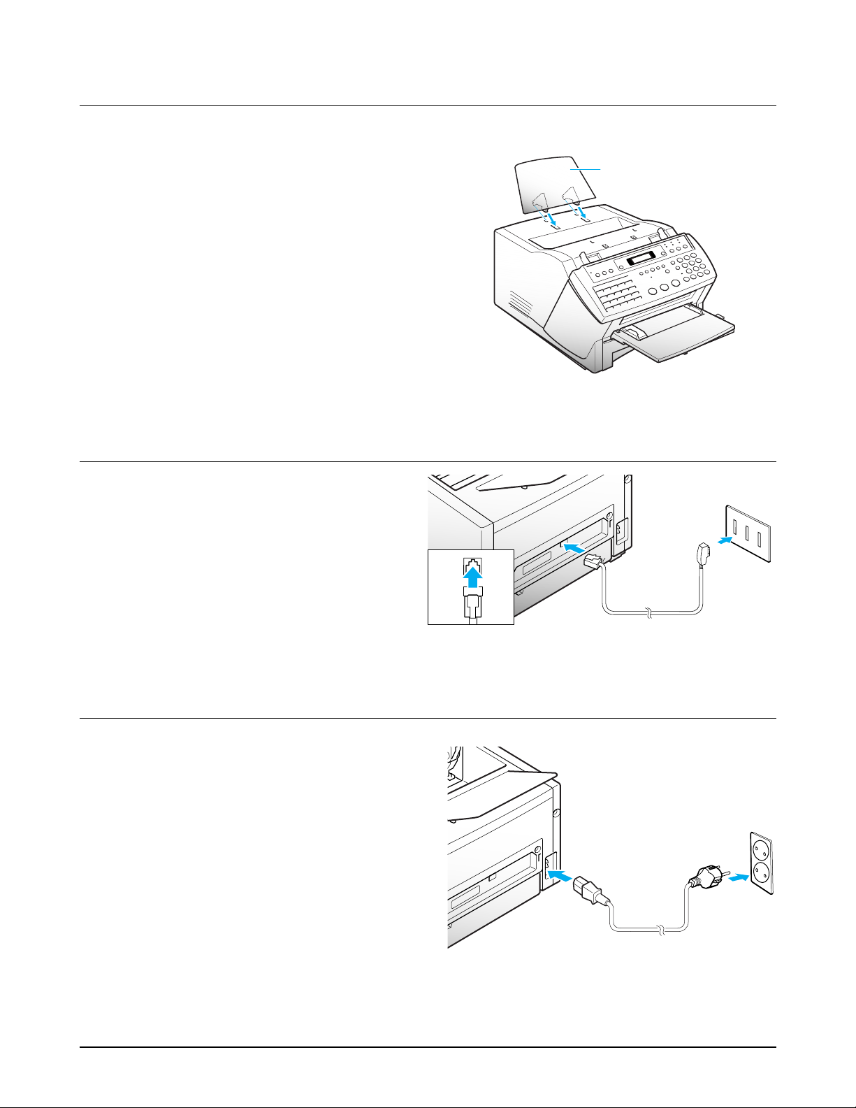
1. Insert two tabs on the document tray into the
corresponding slot as shown.
2. Fold out the extender on the document tray, if
necessary.
Document
tray
Extender
Figure 3.5
Figure 3.3
Figure 3.4
Figure 3.1 Figure 3.2
3-2 Document Exit Tray (and Manual Feeder for upgraded model)
The document exit tray catches documents fed through the machine from the automatic document feeder.
Installation
3-3 Printer Exit Tray
The printer exit tray supports printed output.
1. Insert two tabs on the printer exit tray into the
slots on the top of your machine.
Printer
exit tray
Figure 3.7
Figure 3.8
Figure 3.6
Wandsteckdose
N
F
N
3-4 Telephone Line
Plug one end of the telephone line cord into the
LINE jack and the other end into a standard phone
wall jack.
LINE
3-5 AC Power Cord
Plug one end of the cord into the back of the
machine and the other end into a standard,
grounded 3-prong AC power outlet.
The machine turns on. All lamps on the control
panel light up and the LCD window displays
'WARM UP PLEASE WAIT' then 'NO PAPER
or NO CASSETTE
.' Load the paper as described
on page 3-10.
If you want to power the machine off, unplug the
power cord.
Note : If documents are lost from memory due to a
power failure, the machine automatically prints a
report when power is supplied.
Installation
Figure 3.11
Figure 3.13
Figure 3.10
Figure 3.9
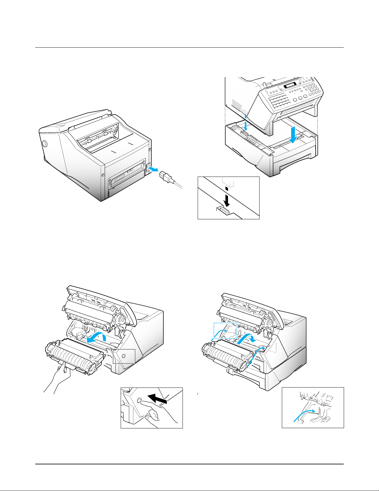
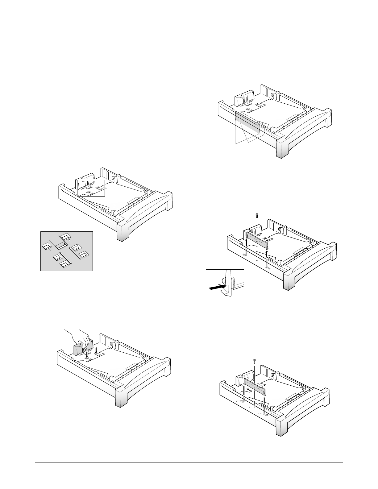
3-6 Second Paper Cassette (Option)
1. Unpack the second paper cassette box. It contains
the second cassette, second cassette frame, and
installation manual.
2. Unplug the power cord, and remove all trays
from the fax machine.
4. Carefully place the fax machine on top of the
second cassette unit, keeping the machine level.
Make sure the connector
is properly inserted.
3. Press the cover release button to open the cover,
and remove the toner cartridge. Then close the
cover.
5. Press the cover release button to open the cover
and install the toner cartridge.
Install all trays, and plug the power cord.
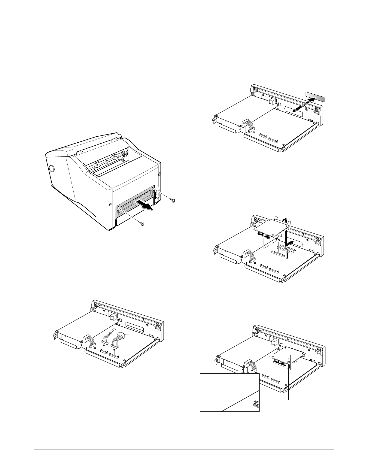
1. Unpack the MFP box. It contains the MFP board,
Printer cable, screws, Installation Software
diskettes, and Installation manual.
2. Unplug the power cord.
3. Remove the two screws and take out the board
cover.
4. Unplug all the connectors from the board.
5. Remove the printer connector cover.
6. Insert the printer connector of the MFP board into
its place, then push down the MFP board so that
the P1 connector on the MFP board is properly
installed into the P3 connector on the main board.
Make sure the PCB supporter is also properly
inserted.
Installation
Figure 3.14
Figure 3.15
Figure 3.16
Figure 3.17
3-7 MFP Board (Option)
This board is required to upgrade this machine to use with PC for PC printing, scanning, and faxing.
Insert the P1 connector
fully until it stops.
PCB supporter
Figure 3.18
Installation
Figure 3.19
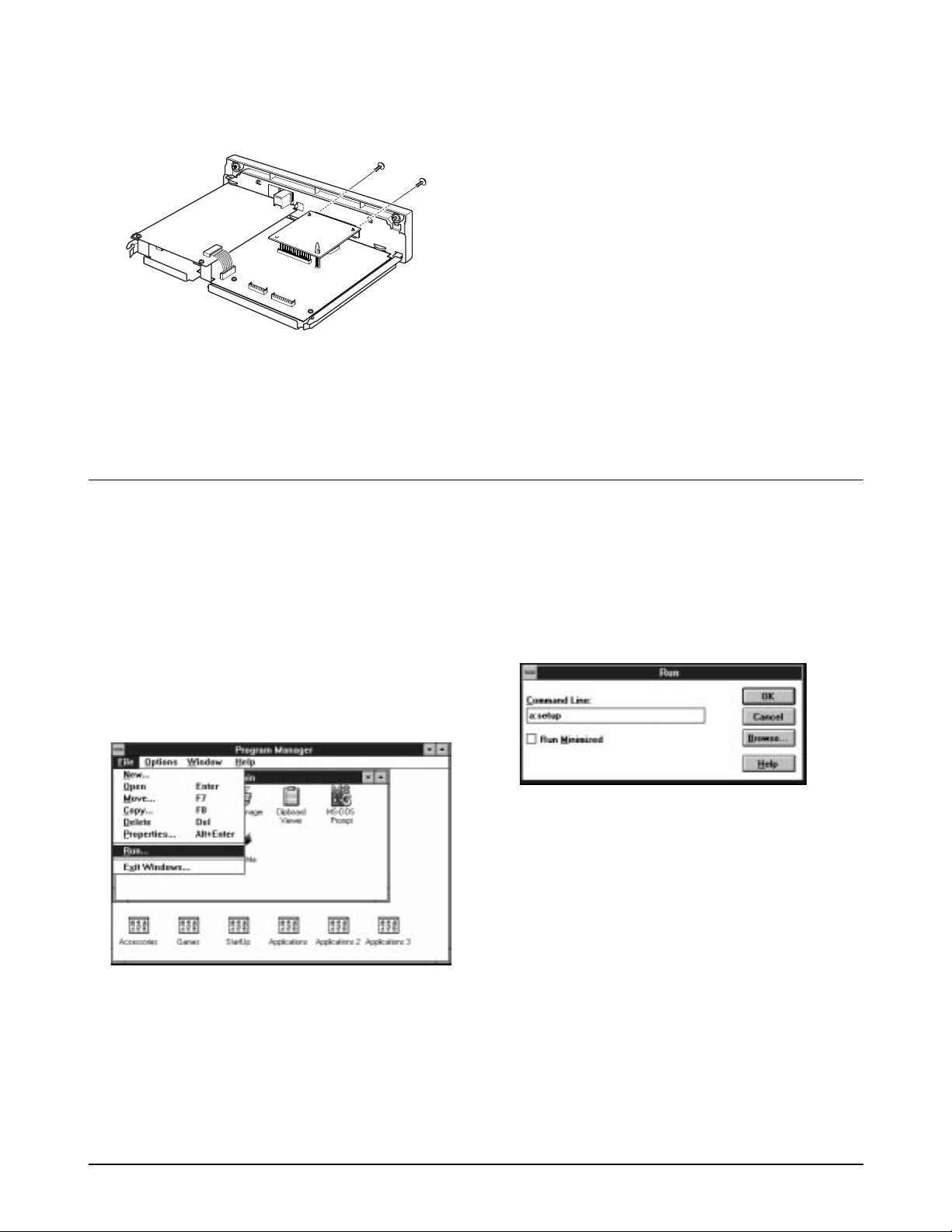
7. Fasten the two screws to secure the printer
connector to the main frame.
8. Plug all the connectors from the two boards into
their places, replace the board cover, and fasten
the two screws.
3-7 Installing the Printer Software
If you have installed the MFP board to this machine, now you need to install this printer software.
3-7-1 With Windows 3.1
1. Start Windows.
2. Insert the setup diskette into drive A (or B)
3. In Windows Program Manager, click on 'File',
then choose 'Run'.
4. In the command box, type 'a:\setup (or b:\setup)',
then click 'OK'.
5. Follow the instructions on the installation
screens.
6. Restart Windows.
Note : For the latest information on installing and
using the printer with Windows applications,
consult the Read Me and Online Help files in the
SF6000 Series MFP program group window.
Installation
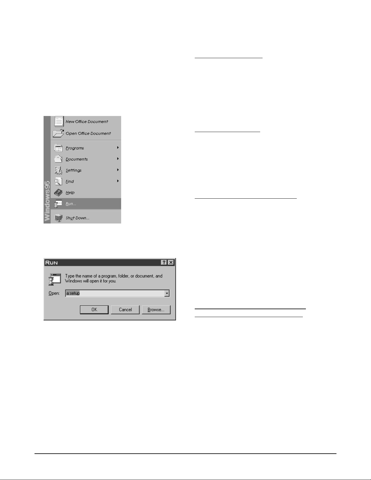
3-7-2 With Windows 95
To install the printer software with Windows 95 :
1. Start Windows.
2. Insert the setup diskette into drive A (or B).
3. Click 'Start' on the desktop, and then choose
'Run'.
4. In the Run dialog box, type 'a:\setup (or b:\setup)',
then click 'OK'.
5. Follow the SF6000 Series MFP Setup instructions.
'SETUP' will install the SF6000 Series software.
Note : Remove the floppy diskette from drive A (or
B) before Windows is restarted.
6. Restart Windows 95.
3-7-3 Running Printer Software
HARDWARE/SYSTEM
Before using the Application Print commands, check
that you have installed your printing device and
software, and turned on the printer. Application
does not show the Print menu if its options do not
apply that is, if you have no scanner or the installed
printer is not GDI-compliant.
BEFORE YOU PRINT
Make sure the SF6000 Series MFP is listed as your
default printer in the Windows Control Panel.
Print as you normally would -for example, by
choosing 'Print' from your applications 'File' menu.
CHANGING PRINTER SETTINGS
1. You can use paper sizes that are : letter - 8.5 X 11
inches, legal - 8.5 X 14 inches, and A4 - 8.2 X 11.7
inches. When you load the paper, adjust the
paper cassette for the paper size you chosen, and
make sure the proper size is set on these printer
software.
2. You can choose the print orientation from
Landscape and Portrait.
3. Resolution is fixed only 300 X 300 dpi.
CHOOSING PRINT OPTIONS FROM
WINDOWS-BASED APPLICATIONS
The following steps are general instructions. Your
Windows-based application may require a slight
variation from procedure. For example, in step 3,
your application may have a 'Printer' button in the
'Printer Setup' dialog box instead of an 'Options'
button.
1. Open the application's 'File' menu.
2. Choose 'Print (or Printer) Setup.'
3. In the 'Print Setup' dialog box, choose 'Options' to
open the 'SF6000 Series' dialog box.

Installation
4. Use the tabs to browse through the available
options.
After choosing print options, you are ready to
print.
CHOOSING PRINT OPTIONS FROM
WINDOWS CONTROL PANEL
1. In the Windows 'Main group' windows, doubleclick the 'Control Panel' icon.
2. From the 'Control Panel', double-click the
'Printers' icon to open the 'Printers' dialog box.
3. From the list of installed printers, select the
'SF6000 Series MFP.'
4. Click the 'Setup' button to open the 'SF6000 Series
MFP' dialog box.
After choosing options, you are ready to print.
3-7-4 Using SF6000 Series MFP
Manager
The MFP manager configures and monitors the
operations of the SF6000 Series MFP. It is a
Windows program that silently runs in the
background all the time. You can open the MFP
Manager display by clicking on it's icon in the
Control Panel menu. You can also terminate the
MFP Manager at any time, if that is necessary. When
you exit the MFP Manager it will offer you two
options. One option is to terminate the SF6000 Series
MFP, and the other option is to keep the MFP
manager running in the background. If you decide
to terminate the MFP manager than all current and
future SF6000 Series MFP usage will be terminated
until you restart the MFP manager or restart
Windows. You can also restart the MFP manager
from the Control Panel menu at any time.
CONFIGURE
Your SF6000 Series MFP can print, scan, and fax. It
appears to your Windows computer as three
separate peripherals: a Printer, Scanner, and a Fax
Modem. These three peripherals appear to be three
separate ports on the cable that attaches the SF6000
Series MFP to your computer. These three SF6000
Series MFP ports are configured automatically
during installation. The cable is also configured
automatically to attach to your computer's LPT1
during installation. However, you can change the
Cable, Print or Fax configuration by pressing the
Configure button.
Cable Port: This is the computer port to which you
connect the SF6000 Series MFP cable. It is configured
automatically to LPT1 during installation. LPT1 is
also configured automatically to use IRQ (7) and
DMA (channel 3) in Windows 3.x. You can connect
the SF6000 Series MFP cable to another LPT port on
your computer. You can also change the IRQ and
DMA assignments for the LPT port in Windows 3.x.
Please consult your computer hardware
documentation for the appropriate IRQ and DMA
assignments. You must restart Windows after you
make changes to the Cable Port LPT, IRQ, or DMA
configuration. The new assignments will become
effective when Windows restarts.
Print Port: This port is pre-configured to LPT3 in
Windows 3.x or LPT4 in Windows 95. You print
Windows documents on the SF6000 Series MFP by
connecting the SF6000 Series MFP printer driver to
this Print Port. You only need to change the
configuration of the Print Port if the LPT3 or LPT4
assignments are in conflict with your PC hardware
or software. You can select another configuration of
the Print Port between LPT2 and LPT9. When you
change the Print Port configuration you will also
need to open the Windows Printer Control and
reconnect the SF6000 Series MFP printer driver of
the new LPT assignment. You must restart
Windows after you make changes to the Print Port
configuration. The new assignment will become
effective when Windows restarts.
Scan Port: This port is pre-configured to COM9 in
Windows 3.x and Windows 95. Your SF6000 Series
MFP Scanner software is automatically configured
to connect to COM9. This assignment is fixed.

Installation
Fax Port: This port is pre-configured to COM3 in
Windows 3.x and Windows 95. You can use the
SF6000 Series MFP as a fax modem by connecting
your Windows fax application to COM3. You only
need to change the configuration of the Fax Port if
the COM3 assignment is in conflict with your PC
hardware or software. You can select another
configuration of the Fax Port between COM3 and
COM8. When you change the Fax Port configuration
you will also need to reconnect your Windows fax
application to the new COM assignment. You must
restart Windows after you make changes to the Fax
Port configuration. The new assignment will become
effective when Windows restarts.
MONITOR
The MFP manager displays the status of SF6000
Series MFP ports when you press the Monitor
button. Active jobs are indicated by the word
'Active' in the Cable, Print, Scan, or Fax port. A
blinking dot also appears next to active port.
EXIT
The Exit button allows you to close the MFP
manager display or terminate the MFP manager.
The MFP manager will display a dialog box when
you press Exit. The dialog box has a Cancel and OK
buttons that mean the following:
Cancel button: This is the default button that you
would normally press to close the MFP manager
display and keep the MFP manager running in the
background. The MFP manager must be running in
the background when you want to use your SF6000
Series MFP.
OK button: This is the button you would press to
terminate the MFP manager. You do not want to
terminate the MFP manager under normal
circumstances. This button is provided for the case
when Windows requests that you terminate all
running programs. The MFP manager is a Windows
program that silently runs in the background all the
time.
If you decide to press the OK button then all
current and future SF6000 Series MFP usage will
be terminated until you restart the MFP manager,
or restart Windows.
You can restart the MFP manager from the Control
Panel menu at any time. Double click on the SF6000
Series MFP icon in Control Panel, press the Exit
button then press the Cancel button. The MFP
manager will silently run in the background and
you can use SF6000 Series MFP again.
UNINSTALL
The Uninstall button allows you to delete the SF6000
Series MFP software from your PC. When you press
the Uninstall button, the SF6000 Series MFP
manager will ask you to confirm that you want all
SF6000 Series MFP software files removed.
If you press the OK button then all of the SF6000
Series MFP files are removed from your PC.
Windows must be restarted when all of the SF6000
Series MFP software files are removed.
Installation
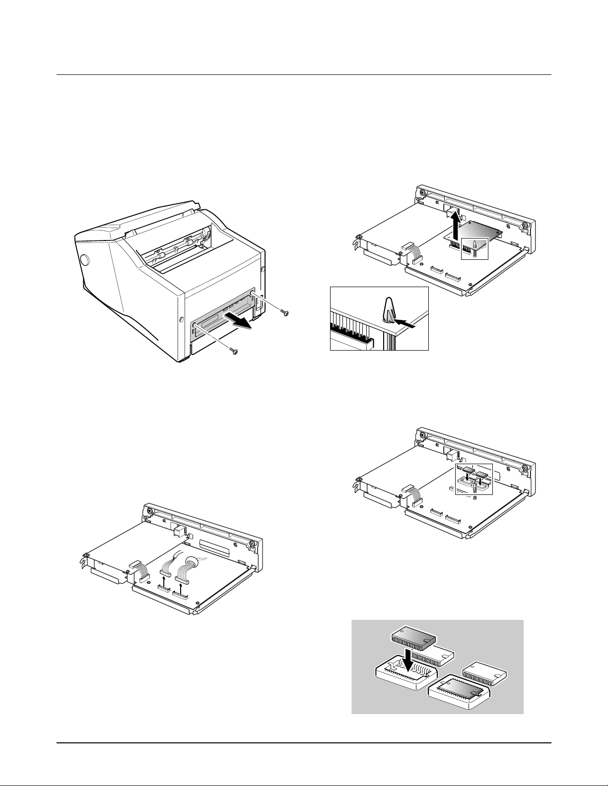
3-8 Memory (Option)
This machine is preset with two 2 Mbyte DRAMs at factory and can be upgraded up to 8 Mbytes by installing
optional two 2 Mbyte DRAMs into the machine. There are two DRAM sockets on the main board of the
machine. If you install one 2 Mbyte DRAM, you can use any socket. You must use KM48C2100 DRAM.
1. Unplug the power cord.
2. Remove the two screws and pull out the board
cover.
3. Unplug all the connectors from the boards, and
take out the board cover.
4. If an optional MFP board have been installed,
remove the MFP board. See 'MFP Board' on page
6-34.
5. Insert one or two KM48C2100 DRAM IC(s) into
the appropriate socket(s) on the main board.
Note : You must observe the correct direction when
you insert the IC. See the direction of the IC
currently inserted.
Figure 3.21
Figure 3.22
Figure 3.20
Figure 3.23
Installation
Figure 3.25
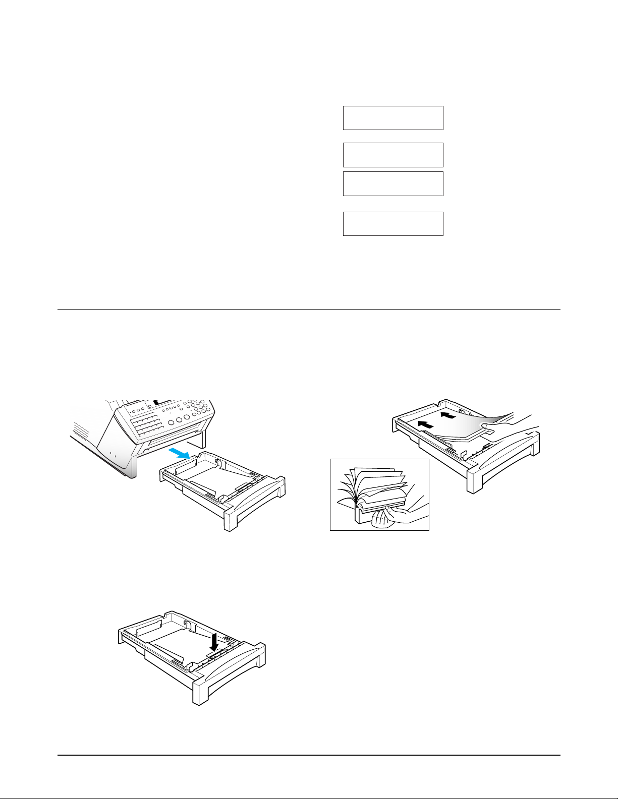
3-9 Loading Paper
The LCD displays 'NO PAPER or NO CASSETTE' when no paper is loaded. You can load approximately
250 sheets of paper.
1. Remove the paper cassette if previously installed,
by pulling it out of the cassette port.
2. To load the paper into the cassette, press down
the metal plate in the cassette.
3. Fan the paper and insert the paper with the print
side facing up.
Note : If you fail to fan the paper, it may cause
multi-paper feeding and jams.
Figure 3.26
6. Plug all the connectors into their places, install
the MFP board if required, reinstall the board
cover, and fasten the screws.
7. Plug the power cord to power the machine on.
8. Get into the Tech mode by Pressing MENU, #, 1,
9, 3, 4.
9. In Tech mode, Press MENU, and one touch 04
ÔSYSTEM SETUP.Õ
10. Press ▼ or ▲ repeatedly until you find 'DRAM
TEST'.
11. Press ENTER. The LCD briefly displays
'TESTING
...
' then shows the result of the
DRAM test as follows:
: Optional two DRAMs
are installed properly.
: Optional one DRAM is
installed properly.
: Optional DRAM is not
installed or not
properly.
Check if the connection
is made properly.
[NO DRAM] OR
[DRAM FAIL]
4M DRAM [OK]
2MDRAM [EVEN-OK]
2MDRAM [ODD-OK]
Figure 3.24
Installation
Figure 3.27
Figure 3.28
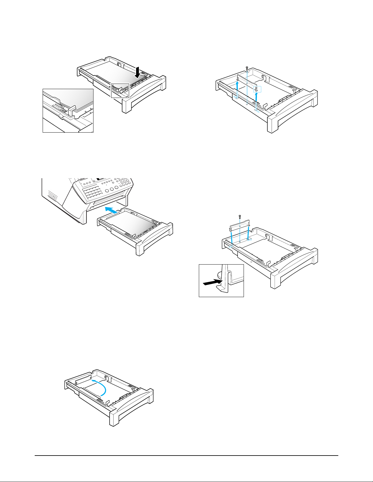
4. Gently press the upper corners of the paper down
under the cassette tabs.
5. Insert the cassette into the port on the front of the
machine until it stops.
Adjusting Paper Guide
The following paper sizes can be used in your
machine:
◆ Letter : 8.5 X 11.0 inches (216 X 279 mm)
◆ A4 : 8.3 X 11.7 inches (210 X 297 mm)
To use Letter size paper, change the position of the
paper guide before loading paper.
1. Remove one screw fastened the paper guide and
take out the guide while pushing the low end
inward.
2. Insert the guide into the slots as shown in the
figure and fasten the screw.
Note : If you want to change the recording paper
size, you must set your machine to use the selected
paper. See 'User Options' on page 3-16. Your
machine is preset to use A4-sized paper.
Figure 3.29
Figure 3.31
Figure 3.30
Installation
Second Lower Cassette (Option)
An optional second cassette can hold three differentsize paper; letter, legal, and A4. The paper cassette is
preset to load the letter-sized paper. If necessary,
adjust the cassette to the desired paper size. You can
use two guides to adjust the cassette. Place the
guides at the appropriate position for the paper size
you want to use.
USING THE REAR GUIDE
1. There are three adjustable positions for the rear
guide, which are marked with the corresponding
paper size.
2. To move the rear guide, push down the tabs of
the guide, and pull the guide inwards or
outwards so that the tabs are placed at the
desired position.
USING THE SIDE GUIDE
1. There are two adjustable positions for the side
guide. If you are using A4 size paper, place the
guide at the front position. Otherwise, place the
guide at the back.
2. To move the side guide, remove the screw
securing the guide and take out the guide while
you push the legs of the guide inwards.
3. Insert the guide into the desired position and
fasten the screw.
LGL
LGL
A4
A4
LTR
LTR
LTR
Letter, legal
A4
Leg
Figure 3.32
Figure 3.33
Figure 3.34
Figure 3.35
Figure 3.36
Installation
3-10 Installing or Replacing Toner Cartridge
When the toner supply is low, a 'TONER LOW' message will be displayed. Remove the toner cartridge and shake
it several times. Several can still be printed before the toner supply runs out completely and the toner cartridge
unit must be replaced.
When the toner supply is depleted, 'TONER EMPTY, REPLACE [CARTRIDGE]' appears in the display.
Supplies are available by contacting your local dex Business Systems representative.
Notes :
¥ When you replace the toner cartridge, you must replace the cleaning felt. If not, the print quality may be
degraded.
¥ When you move the fax machine, do not move it with the toner cartridge installed in the machine. First
remove the toner cartridge then carry the machine.
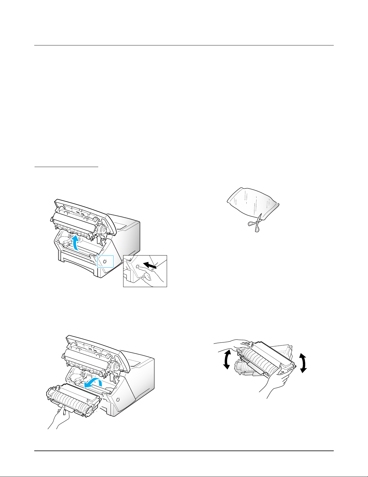
TONER CARTRIDGE
1. Press the cover release button, and fully open the
operation unit assembly.
2. Hold the toner cartridge by the green tab and
remove the used unit, if necessary.
3. Unpack the toner cartridge.
4. Hold the toner unit as shown below and gently
shake it one side up, the other side down, and
vice versa several times to distribute the toner
evenly inside the unit.
Note : If the toner inside the unit is shifted to one
side, it may cause degraded print quality.
Figure 3.37
Figure 3.39
Figure 3.40
Figure 3.38
Installation
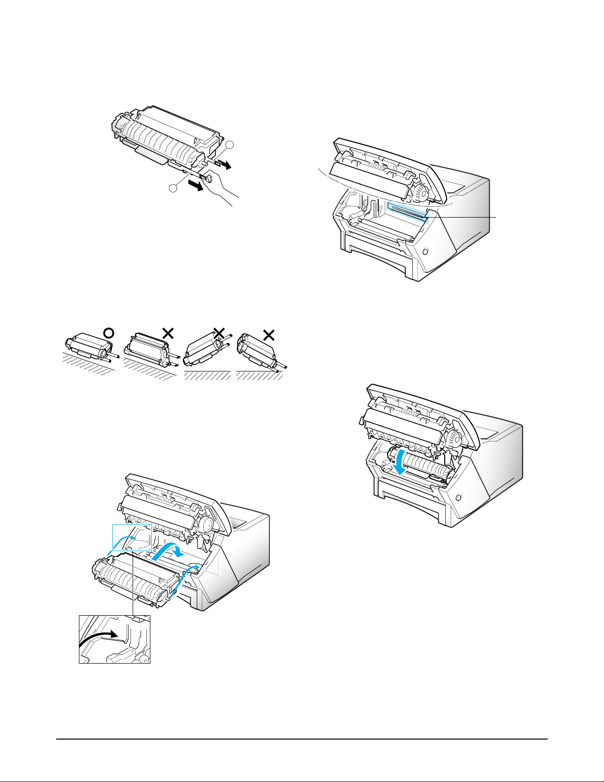
5. Remove the sealing tapes ➀ first, ➁ next, by
pulling them straight out completely. Be careful
not to tear them off.
Warning : When you remove the sealing tapes,
you must hold the toner cartridge horizontally
and pull the tape evenly. Never tip the cartridge
or turn the handle side down. This may cause
degraded print quality.
6. Holding the toner cartridge unit in hand, fit the
tabs on either side of the cartridge the either side
of the compartment as shown, and slide it down
firmly into your fax machine until it clicks in
place.
Warning : Your machine is designed to stop the
machine operation and cut off the laser beam that
can damage your eye if the cover is opened.
However, for safety's sake, do not look at the LSU
window in front where the laser beam might
come out when you open the cover.
7. After installing the toner cartridge, close the
operation unit assembly.
Figure 3.41
Figure 3.43
Figure 3.44
LSU Window
Figure 3.42
1
2
Installation
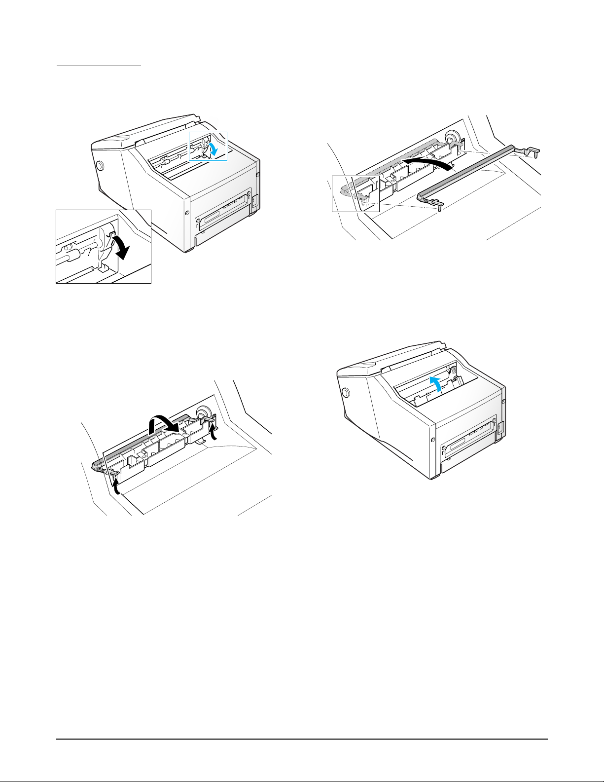
3. Insert new cleaning with the white felt faced out
as show.
CLEANING FELT
1. Open the fuser cover by pulling the release lever.
2. Remove the cleaning felt used.
4. Close the fuser cover.
Note : You must install a new cleaning felt when
you install a new toner cartridge. If not, the print
quality may be degraded.
Figure 3.45
Figure 3.46
Figure 3.47
Figure 3.48

Installation
3-11 Memory Clear
3-11-1 Memory Clear in User Mode
In the user mode, you can selectively clear
information stored in this machine's memory. The
list of data you can clear is as follows:
1:SYSTEM ID : your terminal ID number and name
are erased from the machine's memory.
2:SYSTEM DATA : restores user-selectable options
to the default value.
3:DIAL & DELAYED : clears the One-Touch, Speed
Dial, or Group Dial numbers stored in memory.
In addition, all the delayed time operations you
have reserved are also canceled.
4:TX-RX JOURNAL : clears all records of
transmissions & receptions.
1. If the machine is in the tech mode, return to the
user mode by pressing MENU, #, 1, 9, 3, 4 in
sequence.
2. Press MENU, and the one-touch key 5
'MEMORY CLEAR'.
The LCD displays the type of memory you can
choose.
3. Scroll to the options by pressing or ¹ until you
find the one you want to clear. When the cursor
blinks under the memory you want to clear, press
ENTER.
Otherwise, you can enter the number of the
memory.
4. The LCD prompts you to confirm your selection.
Press ENTER. If you press STOP, the machine
returns to Standby Mode.
3-11-2 Memory Clear in Tech Mode
Memory clear, contained in the tech mode, is used
for clearing all the user's data in memory and setting
to default status.
1. If not in the tech mode, Press MENU, #, 1, 9, 3, 4
in sequence to initiate the tech mode.
2. Press MENU, and the one-touch key 5
'MEMORY CLEAR'.
The LCD displays 'MEMORY ALL CLEAR'.
3. Press 1 to clear all memory.
If you want to cancel, press 2. The machine
returns to Standby Mode.
3-12-1 System Data Settings in User-mode
The fax machine has various user-selectable
functions. These functions are usually selected
during the initial setup of the machine, and there
should be little need to change them there after.
Note : Before you begin, print out the system data
list to see the current settings. To print the system
data list, press MENU, and one-touch 19 'SYSTEM
DATA.'
1. Press MENU, then one-touch 01 'SYSTEM DATA.'
The LCD displays user-selectable options.
2. Scroll to the options by pressing ▼ or ▲ repeatedly.
3. When the option you want appears in the display,
enter the number for the desired status. You can
use à or ¨ button and press ENTER to select the
desired status.
3-12-2 User-Selectable Options
These instructions assume you've followed the steps
under 'System Data Settings in User-mode' and the
machine is asking if you want to change one of the
options listed here.
3-12 System Data Set-up
There are system data settings that are set by the user in the user-mode, and system data settings set by the
technician in the tech mode.

Installation
Paper Size-Select the paper size you will use for
the recording paper.
Press 1 for letter (LTR) or, 2 for A4 size paper.
If your machine is equipped with an optional lower
cassette, select the paper size for the lower cassette.
Press 1 for letter (LTR), 2 for A4, or 3 for legal (LGL)
size paper.
Message Confirmation Report-A confirmation
report shows whether the transmission was
successful or not, how many pages were sent, etc.
Press 1 to print out journal automatically each time
you send a fax.
Press 2 to print only when an error occurs and the
transmission was not successful.
Auto Print Journal-A journal report shows specific
information concerning transmission and reception
activities, the time and dates up to 50 of the most
recent transmission and reception.
Press 1 to print journal automatically after every 50
transmission and receptions.
Press 2 to print journal manually.
Remote Receive Start Code-The remote receive
code allows you to initiate fax receive from an
extension phone. If you pick up the extension phone
and hear fax tones, enter the remote receive code
and the fax will start receiving. The password is
preset to 9 at factory.
Enter the desired code 0 to 9 on the number keypad.
Power Save Mode-The power save mode allows
you to shut off the machine's printer heater
automatically after a document is printed, to
conserve electricity and reduce your utility bills. The
fax machine automatically turns on the printer again
when it receives a document or is instructed to make
a copy. In this mode, it takes the machine a little
longer to print out fax messages or copies since it
must first re-heat the printer.
Press 1 to turn this feature on. If you want to set the
time duration that the machine activates the power
save mode, enter the time in 24-hour format.
Press 2 to turn this feature off.
Dial Mode-Select the type of dial system your fax
machine is connected to.
Press 1 if the fax machine is connected to a tone
(Touch Tone) dial line.
Press 2 if the fax machine is connected to a pulse
(Rotary) dial line.
Security Communication-This mode allows your
fax machine to send and receive documents to and
from a predetermined location where the fax
machine has the security code that matches your
security code.
Press 1 to turn on the Security Communication
mode.
Press 2 to turn off the Security Communication
mode.
Error Correction Mode-This mode compensates for
poor line quality and ensures accurate, error-free
transmission with any other ECM-equipped
facsimile machine. If the line quality is poor,
transmission time may be increased when ECM is
enabled.
Press 1 to turn on the error correction mode.
Press 2 to turn off the error correction mode.
Automatic Reduction in Receiving-When
receiving a document as long as or longer than the
paper installed in your machine, the machine can
reduce the data in the document to fit on your
recording paper size. The machine will reduce the
data in vertical. If you have an optional lower
cassette, your machine will automatically select the
cassette in which the desired-size paper is loaded.
Turn on this feature if you want to reduce an
incoming page that may otherwise need to be
divided into two pages with only a few centimeters
on the second page. If the fax machine cannot reduce
the data to fit into one page with the feature enabled,
the data is divided and printed in actual size on two
or more sheets if needed.
Press 1 to turn this feature on.
Press 2 to turn this feature off. The overflowed data
will be printed out on a second page.
Installation
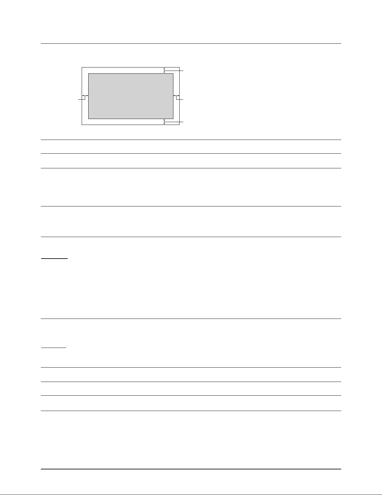
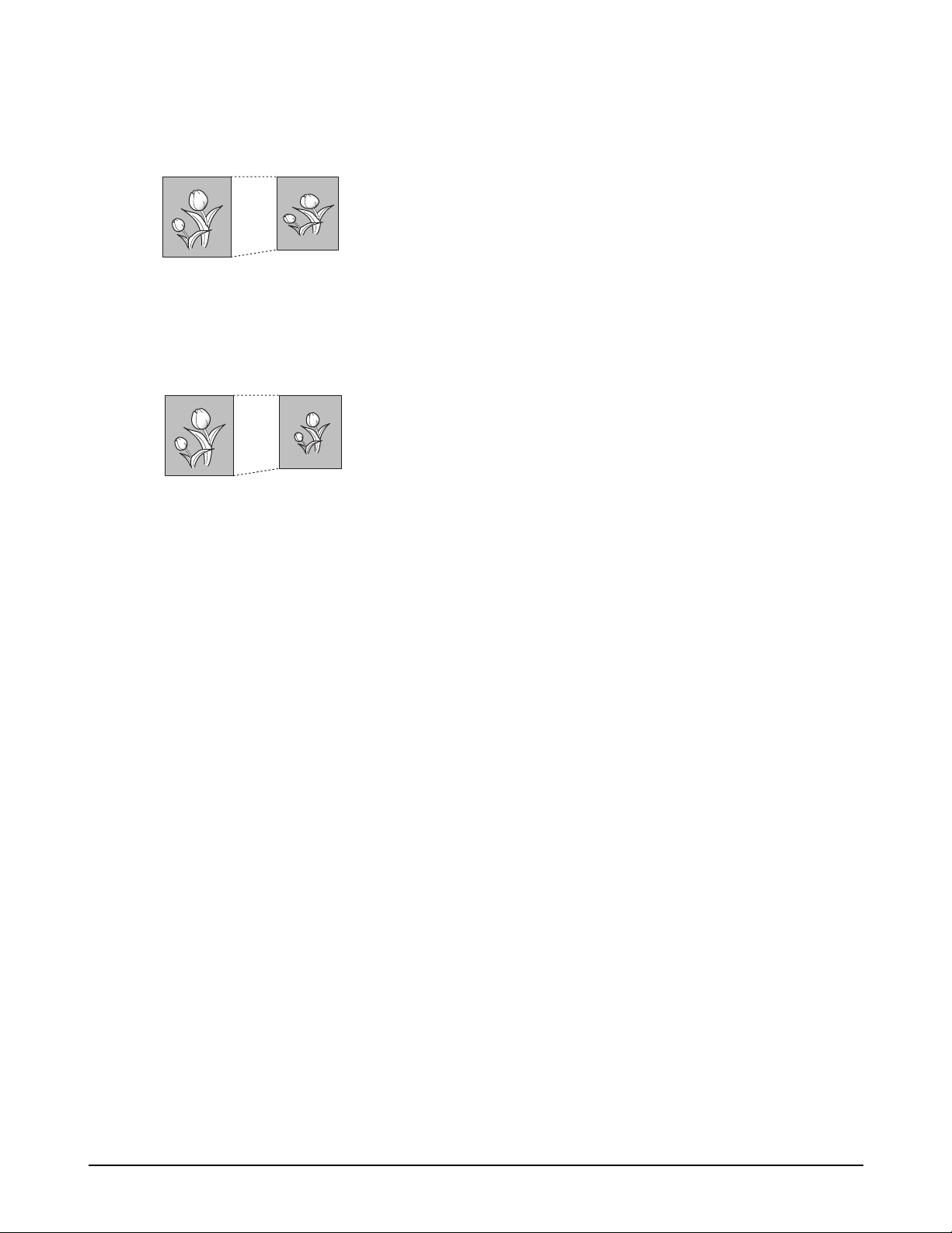
Horizontal Reduction-When you turn on the
automatic reduction feature and an incoming page
contains overflowed data, the machine reduce the
data only in vertical as shown below.
If you want to reduce both in vertical and horizontal
at the same rate in order to maintain height to width
relationships, use the horizontal reduction option. If
you turn on this feature, the machine reduces the
data as shown below.
Press 1 to turn this feature on.
Press 2 to turn this feature off.
Automatic Discard Size-When receiving a
document as long as or longer than a standard letter
size paper installed in your fax machine, you can set
the fax machine to discard any excess image at the
bottom of the page to fit the recording paper size.
If the received page is outside the margin you set, it
will be printed on two sheets of paper at the actual
size.
If the data is within the margin, and the Rx
Reduction feature is turned on, it will be reduced to
fit in the appropriate size paper (Discard does not
take place). If the Rx Reduction feature is turned
OFF or fails, the data within the margin will be
discarded.
Enter the desired discard size using the number
keypad, and press ENTER.
Automatic Redial Term-Your fax machine can
automatically redial a remote fax machine if it was
busy or does not answer the first call.
Enter the number of minutes (from 1 to 7) using the
number keypad.
Automatic Redial Try-Enter the number of
attempts (from 0 to 7) to redial the number before
giving up.
If you enter 0, the machine will not redial.
Ring Before Answer-You can select the number of
times your machine rings before answering an
incoming call. If you are using your machine as both
a telephone and a fax machine, we suggest you set
the ring count to at least 4 to give you time to
answer.
Enter a number from 1 through 7 on the number
keypad.
Smoothing-The smoothing feature enhances the
appearance of incoming faxes by making the lines
smooth and takes no additional time. This function
does not apply to outgoing faxes, or to lists or
reports you print. It is recommended to turn this
feature on for text data, turn it off for picture image.
Press 1 to turn the feature on.
Press 2 to turn the feature off.
Continuous Polling Report-Every time continuous
polling ends, a multi-communication report will be
printed to show the result for each registered station.
Press 1 to print the report automatically each time
continuous polling ends.
Press 2 to turn the feature off. The report will not be
printed.
Forced Memory Transmission-If you are annoyed
that you have to wait until documents in the feeder
are sent out when you try to send or reserve another
fax, turn this feature on. This feature enables all
transmission documents are automatically scanned
into memory before transmission. Memory might be
full.
Press 1 to turn this feature on.
Press 2 to turn this feature off. The LCD display
prompts you to choose either to scan the documents
into memory or not before dialing the number when
you try to send or reserve a fax.
Original Received data
Original Received data

Installation
Receive Terminal Identification-This feature
allows the machine to automatically print the
receive terminal ID (if registered), page number,
reduction rate, and the date and time of the
reception at the bottom of each page of a received
document.
Press 1 to turn this feature on.
Press 2 to turn this feature off.
Print Priority Term-This option is available only
when you install an optional MFP board into your
machine. When you want to print a PC document
while the machine prints a received fax on the
recording paper, you can interrupt the printing and
print the PC document. Press the PRINT PRIORITY
button to enable the feature. The LCD displays PP
on the lower line, right corner. The interrupted fax
data will be stored in memory. To disable, press the
PRINT PRIORITY button again. PP on the LCD
disappears.
You can set your machine to turn the feature off
automatically if there is no further data printed
within 30 minutes or 8 hours after PC printing.
Press 1 to select 8 hours. The machine turns off
automatically 8 hours after PC printing is
completed.
Press 2 to select 30 minutes. The machine turns off
automatically 30 minutes after PC printing is
completed.
3-14-3 Confiming System Data Settings
Confirm the system data settings by printing out a
system data list.
1. If not in the tech mode, press MENU, #, 1, 9, 3, 4 in
sequence to initiate the tech mode.
2. Press MENU.
3. Press one of the one-touch PRINT keys 16-20. The
LCD displays the lists you can print out.
4. Press or ¹ until you find 'SYSTEM DATA
LIST'.
5. Press ENTER. The machine prints the system
data list.
The system data list printed in the tech mode
contains the system data set in the tech mode as
well as in the user mode. The model number and
software version will be printed at the bottom of
the system data list.

Installation
3-14-4 System Data Settings in T ech-mode
Various technical features of fax machine are
provided with optional parameters. Set the features
to the user's need according to the following
procedure.
1. If not in the tech mode, press MENU, #, 1, 9, 3, 4
in sequence to initiate the tech mode.
2. Press MENU, one-touch 1 'SYSTEM DATA.'
The LCD displays 'TECH MODE SYSTEM DATA?'.
3. To set the system data available in tech mode,
press ENTER.
If you want to set the system data available in the
user mode, press STOP. The LCD displays 'USER
MODE SYSTEM DATA?'. Press ENTER to set the
system data available in the user mode.
4. The LCD displays the options you can choose. In
tech mode, the LCD displays the technicianselectable options as well as all the user-selectable
options.
5. Scroll to the options by pressing or ¹
repeatedly.
6. When the option you want appears in the display,
enter the number for the desired status. You can
use à or ¨ button and press ENTER to select the
desired status.
You can exit from setup mode at any time by
pressing STOP. When you press STOP, the
machine stores the options you've already changed
and returns to Standby mode.
FEATURE
Modem Speed 33600/28800/
14400/12000
9600/7200
4800/2400 bps
The maximum Tx speed can be limited to 33600, 28800, 14400, 9600, 7200, 4800 or
2400 bits per second. When the Tx speed is set to 33600 or 28800, the Rx speed can
be V.34. When the Tx speed is set to 14400, the Rx speed can be either V.33 or V.17
speed. When the Tx speed is set to 9600 or 7200, the Rx speed can be either V.29 or
V.27ter speed. When the Tx speed is set to 4800 or 2400, the Rx speed can be any
V.27ter speed.
Error Rate 6%, 12% If the error rate exceeds the chosen rate, fall back occurs which will lower the
baud rate automatically down to as low as 2400 baud until the error rate is less
than the chosen rate.
Tx Level -4 ~ -15 dBm You can set the level of transmission signal. Typically, Tx level should be under
-12 dBm. The level within the range of -4 dBm to -15 dBm is acceptable. Enter the
desired value using the dial keypad.
Super Fine Scan
to Memory
off/200/300 dpi
This feature allows the machine to scan documents in super fine resolution (200 X
400 dpi, 300 X 300 dpi). The other machine can receive super fine image. If the
remote machine is not capable of receiving super fine data, your machine fails to
send documents and displays 'INCOMPABLE ERROR'.
PARAMETER FUNCTION
Ring On Check
Time
Ring Off Check
Time
The machine must receive a ring signal with a specified active time from a
telephone exchange in automatic reception mode. The detection time that the
machine considers valid is adjustable via this option. If the active time of the ring
signal is less than the set value of the Ring On Check Time,the machine will not
consider it a ring signal.
The machine must receive a ring signal with a specified inactive time,as well as an
active time. If the inactive time of the ring signal is longer than the value of the
Ring Off Check Time,the machine will not consider it a valid ring signal.

Installation
3-14 LCD Display
3-14-1 During Communication
In user mode, the LCD shows the remote machine's
TTI number, TX or RX communication type,
(modem speed), and page number.
In service mode, the display shows the
communication type, abbreviations for the CCITT
Group 3 T.30 protocol as they occur, the protocol
type (G3), baud rate in kbps, and line time.
3-14-2 If a Communication Problem Occurs:
In user mode, the display shows one of the
following:
PAPER JAM, COMM.ERROR, LINE ERROR.
In service mode, the display shows all error
messages available in user mode, as plus additional
error messages available only in Service Mode.
Error messages shown in service mode only are as
follows:
PRE-MESSAGE ERROR : problem occurred during
phase B of session.
POST-MESSAGE ERROR : problem occurred during
phase D of session.
MESSAGE ERROR : problem occurred during phase
C of session.
LINE ERROR : machine cannot connect or has lost
connection with the remote machine.
Additional messages, not shown above, will appear
in the TX/RX journal printed in service mode.
Samsung Electronics 6-1
6. Disassembly and Reassembly
6-1 General Precautions on Disassembly
When you disassemble and reassemble components, you must use extreme caution. The close proximity of
cables to moving parts makes proper routing a must. If components are removed or replaced, any cables
disturbed by the procedure must be restored as close as possible to their original positions. Before removing any
component from the machine, note the cable routing that will be affected.
Whenever servicing the machine, you must perform as follows:
1. Check to verify that no documents are stored in memory. You can check it by printing the Delayed Dial List.
Press MENU, one-touch 17 'DELAYED DIAL', ENTER sequentially.
2. Remove the paper cassette, trays, and toner cartridge.
3. Unplug the power cord.
4. Use a flat and clean surface.
5. Replace with only an authorized component.
6. Do not force to open or fasten a plastic-material component.
7. Be careful no obstacles are included when you reassemble components.
8. When you assemble components, be careful small-sized components are located in place.
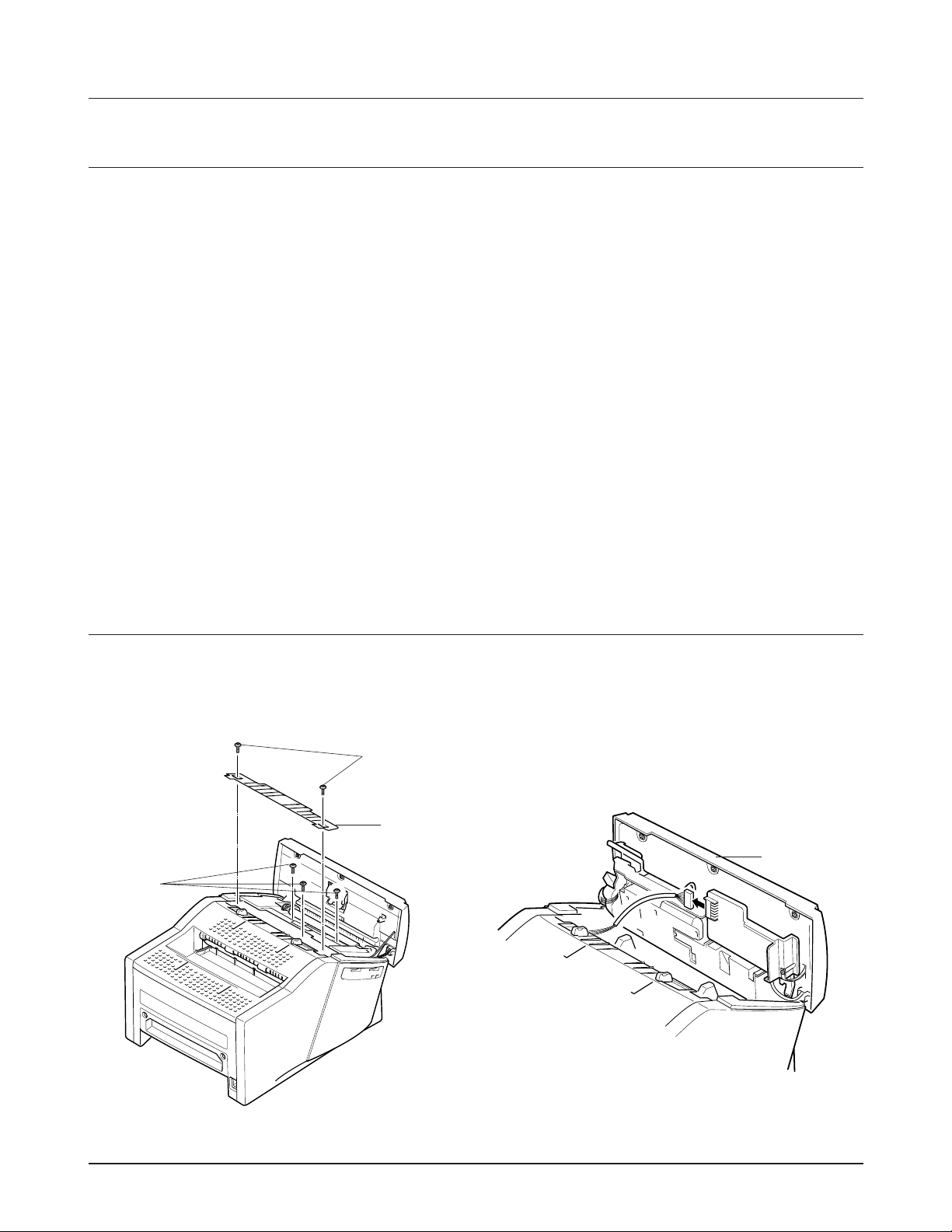
6-2 Scan Unit
1. Open the control panel by hand, remove the two
screws A. Remove the TX piece. Then remove
three screws B.
2. Close the Control panel, and take out the Scan
unit. Unplug the connector from the Scan PBA.
Figure 6.1 Figure 6.2
TX piece
Scan Unit
B
A
 Loading...