

Samsung SF6500 Disassemble
Samsung Electronics 6-1
6. Disassembly and Reassembly
6-1 General Precautions on Disassembly
When you disassemble and reassemble components, you must use extreme caution. The close proximity of
cables to moving parts makes proper routing a must. If components are removed or replaced, any cables
disturbed by the procedure must be restored as close as possible to their original positions. Before removing any
component from the machine, note the cable routing that will be affected.
Whenever servicing the machine, you must perform as follows:
1. Check to verify that no documents are stored in memory. You can check it by printing the Delayed Dial List.
Press MENU, one-touch 17 'DELAYED DIAL', ENTER sequentially.
2. Remove the paper cassette, trays, and toner cartridge.
3. Unplug the power cord.
4. Use a flat and clean surface.
5. Replace with only an authorized component.
6. Do not force to open or fasten a plastic-material component.
7. Be careful no obstacles are included when you reassemble components.
8. When you assemble components, be careful small-sized components are located in place.
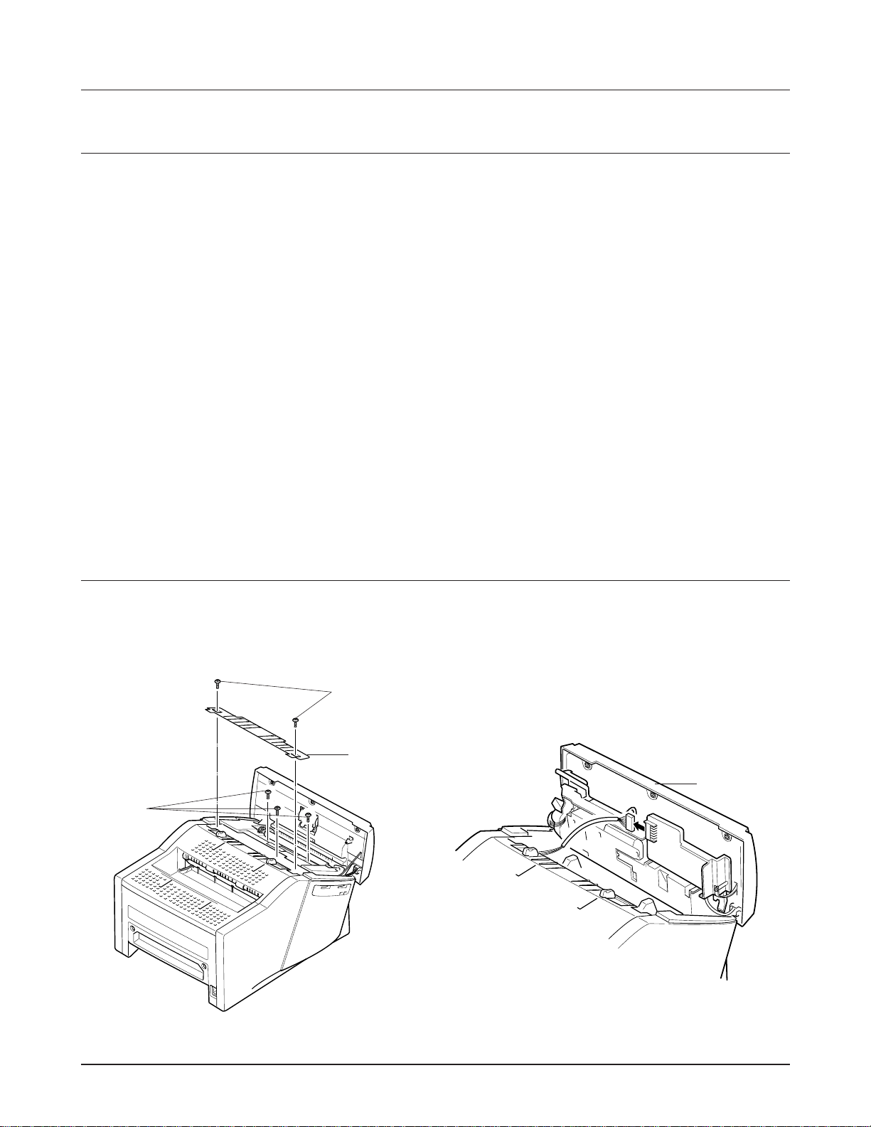
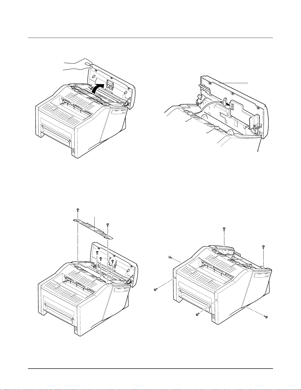
6-2 Scan Unit
1. Open the control panel by hand, remove the two
screws A. Remove the TX piece. Then remove
three screws B.
2. Close the Control panel, and take out the Scan
unit. Unplug the connector from the Scan PBA.
Figure 6.1 Figure 6.2
TX piece
Scan Unit
B
A
Disassembly and Reassembly
6-2
Samsung Electronics
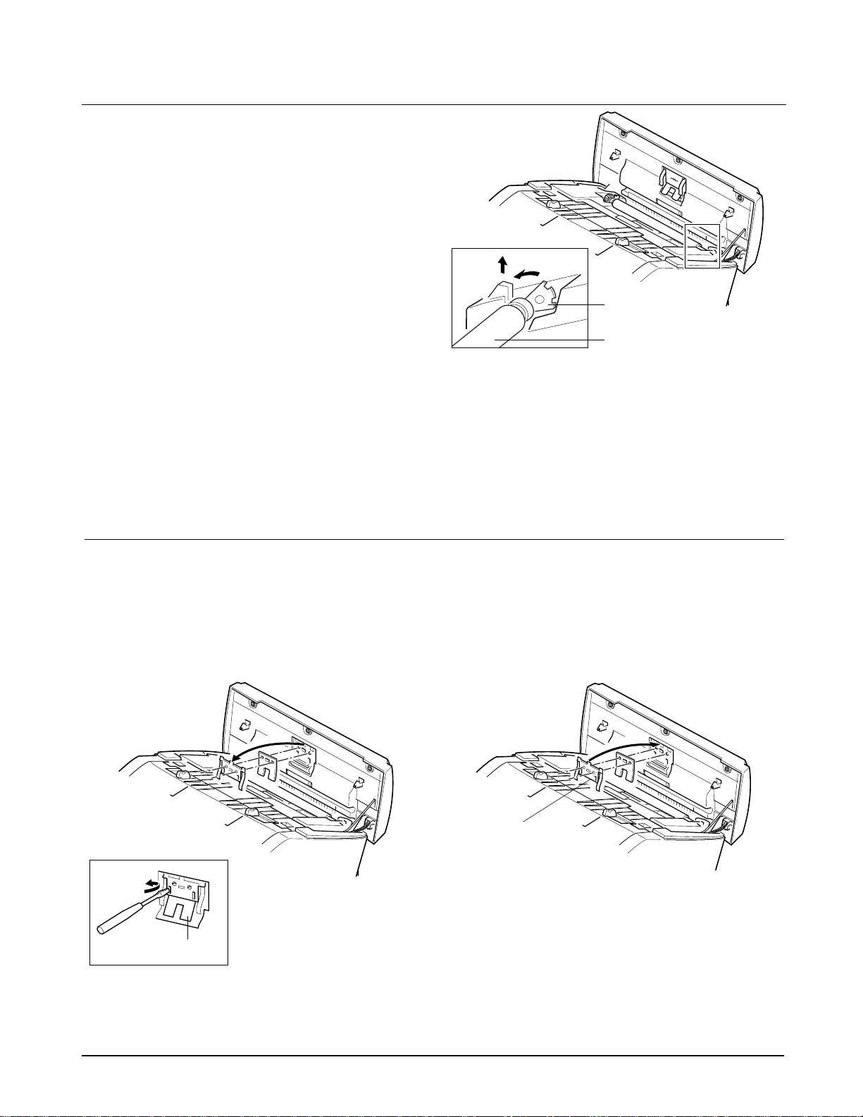
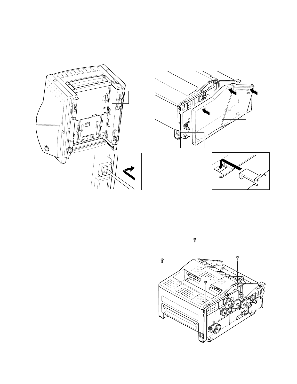
6-4 ADF Rubber Pad
1. Open the control panel by hand.
2. Insert a flat blade screw driver into the slot and
force to remove the rubber as shown in the
figure below.
6-3 White Roller Assembly
1. Open the control panel by hand.
2. Push the bushing at both ends of the roller
slightly inward, then rotate it in the direction of
(A) until it reaches the slot as shown in the figure
below. Then take out the roller in the direction
of (B).
Notes: When you reassemble the pad, be sure that
the rubber pad and holder fit into the guide
boss and the holder tabs fit into the
corresponding hole. Then push them firmly
until it clicks.
¥ Clean the surface of the rubber pad with ethyl
alcohol. After wiping it, be sure to dry completely
with a soft cloth. Check the rubber wear. If the
wear reaches 1/2 its original thickness, replace it
with a new one.
Bushing
White roller
Figure 6.3
Figure 6.4
Figure 6.5
A
B
ADF rubber
Guide boss
Note: Check the roller for any stain. If stained, wipe
it off with soft cloth dampened with alcohol.
If the roller is heavily worn, replace it with a
new one.

Disassembly and Reassembly
6-3
Samsung Electronics
OPE unit
Figure 6.7
Figure 6.6
6-5 OPE Unit
1. Before you disassemble the OPE unit, you
should remove :
¥ Scan unit (See page 6-1)
2. Turn the scan unit over. Place the unit on soft
cloth to avoid the accidental scratch on the
surface of the unit.
3. Unplug the OPE connector from the scan PBA
and remove the one earth screw.
4. Open the OPE cover. Twist the tie stopper until it
is released. The OPE unit has secured by the tabs
on the bottom end to the Scan unit as shown.
Pull the tabs outwards so that the OPE unit is
separated from the Scan unit.
Tab
Tie stopper
Samsung Electronics6-4
Disassembly and Reassembly
Scan paper guide
CIS
Figure 6.8
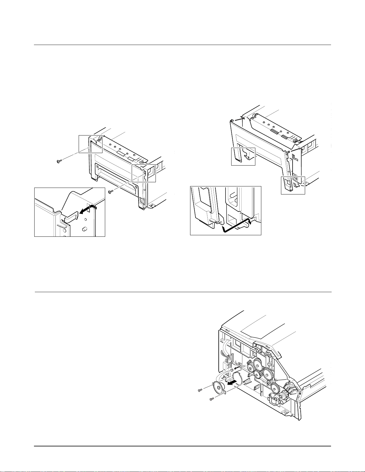
6-6 CIS
1. Before you disassemble the CIS, you should
remove :
♦ Scan unit (See page 6-1)
♦ White roller (See page 6-2)
♦ OPE unit (See page 6-3)
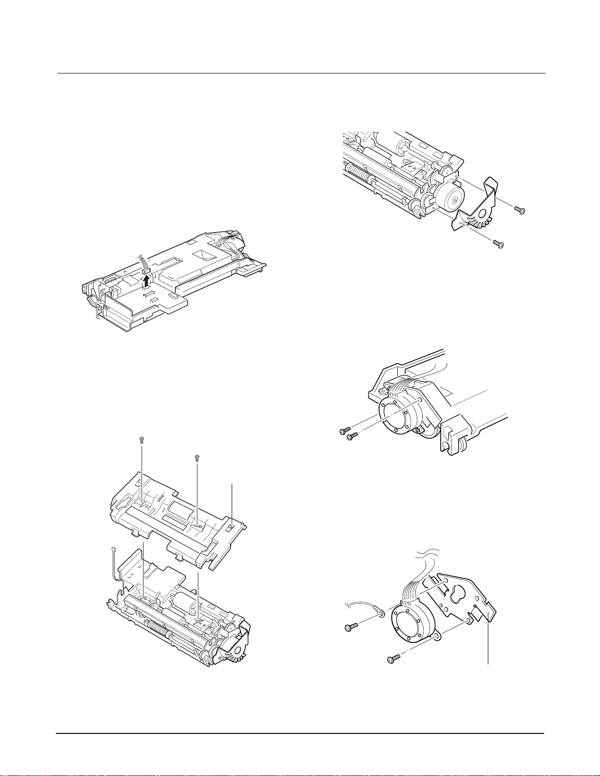
2. Remove the two screws securing the Scan paper
guide and take out the paper guide.
3. Remove the one special screw securing the CIS.
Figure 6.9
A
B
4. Unplug one connector from the CIS. Pull up the
left end of the CIS, then take out the CIS in the
direction of B.
Figure 6.10
Notes:
¥ After you replace the CIS, you must perform the
Make shading procedure. For details, see page 7.3.
¥ Check the glass surface of the CIS for any stain or
scratch. If stained, wipe off with ethyl alcohol. If it
is heavily stained or scratched, replace it with a
new one.
¥ When you assemble the scan paper guide, make
sure the tabs in the guide fit in place.
Figure 6.11
Disassembly and Reassembly
6-5
Samsung Electronics
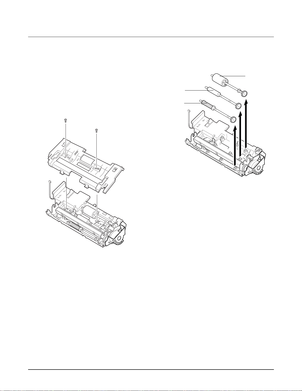
Note: Clean the surface of the rollers with ethyl
alcohol. After wiping them, be sure to dry
completely with a soft cloth.
6-7 Rollers (ADF, Feed, D.Exit)
1. Before you disassemble the roller, you should
remove :
♦ Scan unit (See page 6-1)
♦ White roller (See page 6-2)
♦ OPE unit (See page 6-3)
2. Remove the two screws securing the scan paper
guide and take out the Scan paper guide.
Figure 6.8
3. Take out the rollers from the Scan unit.
Figure 6.12
ADF roller
Feed roller
D. Exit roller
Samsung Electronics6-6
Disassembly and Reassembly
3. Turn the Scan unit back. Remove the two screws
securing the Scan paper guide, and take out the
scan paper guide.
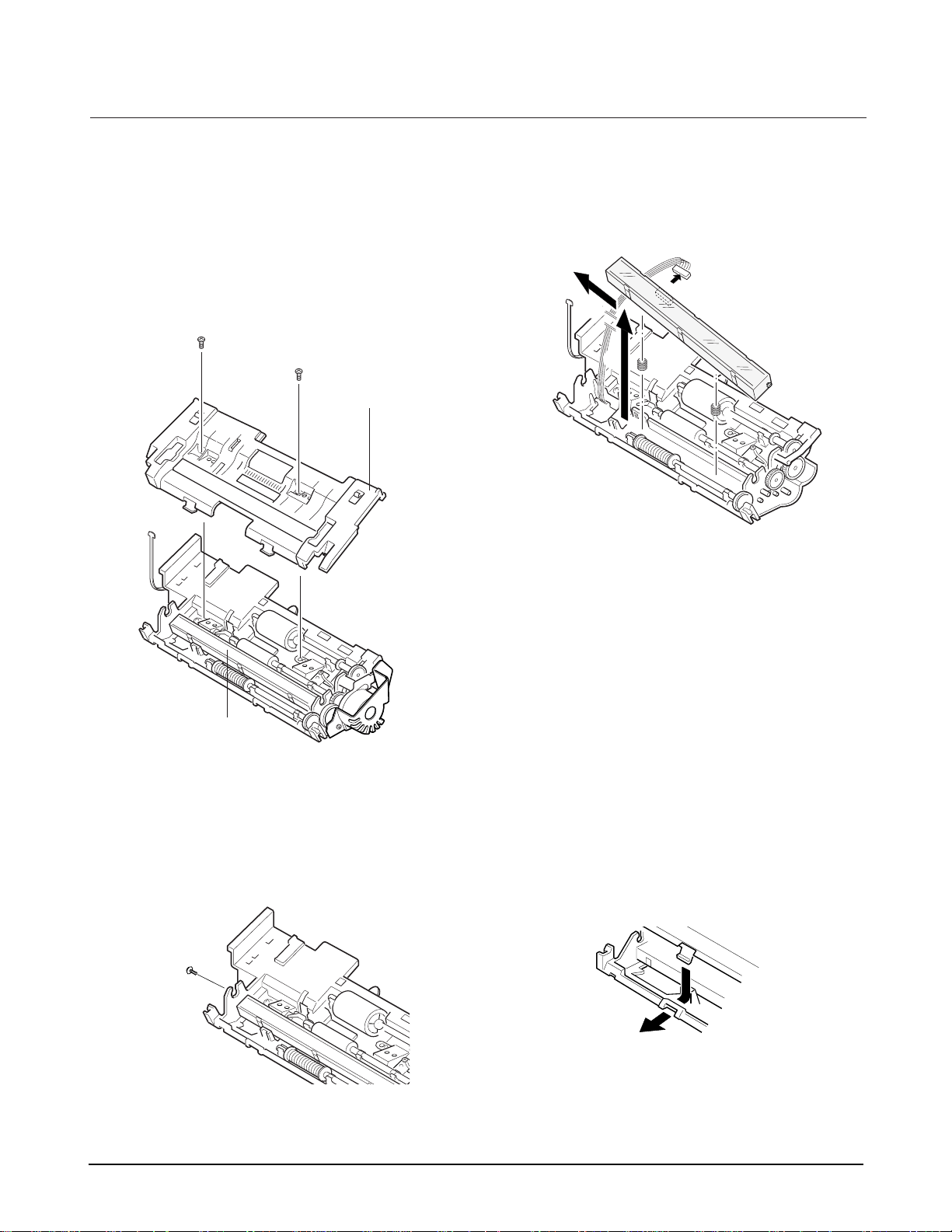
6-8 Scan Motor
1. Before you disassemble the Scan motor, you
should remove :
♦ Scan unit (See page 6-1)
♦ White roller (See page 6-2)
♦ OPE unit (See page 6-3)
2. Turn the scan unit over and unplug the motor
connector from the Scan PBA.
Figure 6.13
Figure 6.8
Scan Paper Guide
4. Remove the two screws securing motor cover
and take out the motor cover.
6. Remove the two screws securing the motor to the
motor bracket.
Motor bracket
Figure 6.14
Figure 6.16
5. Remove the two screws securing the motor to the
Scan unit, and take out the motor ass'y.
Figure 6.15
Disassembly and Reassembly
6-7
Samsung Electronics
6-9 Roll Pinch
1. Before you disassemble the Roll pinch, you
should remove :
♦ Scan unit (See page 6-1)
♦ OPE unit (See page 6-3)
2. Remove the five screws from the OPE unit.
3. Turn the scan upper frame of the OPE unit over.
4. Remove the three screws and take out the spring
pinch. The roll pinch is separated.
Figure 6.17
Figure 6.18
Roll pinch
Spring pinch
6-10 Scan PBA
1. Before you disassemble the Scan PBA, you
should remove :
♦ Scan unit (See page 6-1)
2. Turn the Scan unit over and unplug all
connectors from the scan PBA.
3. Remove the one screw securing the Scan PBA
and take out the PBA.
Figure 6.19
Figure 6.20
6-8 Samsung Electronics
Disassembly and Reassembly
6-11 OPE PBA
1. Before you disassemble the OPE PBA, you
should remove :
♦ Scan unit (See page 6-1)
♦ OPE unit (See page 6-3)
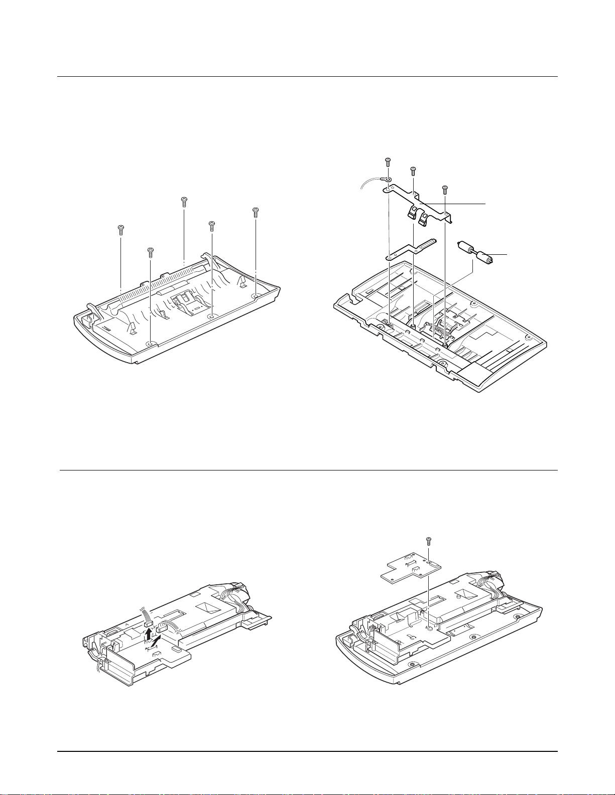
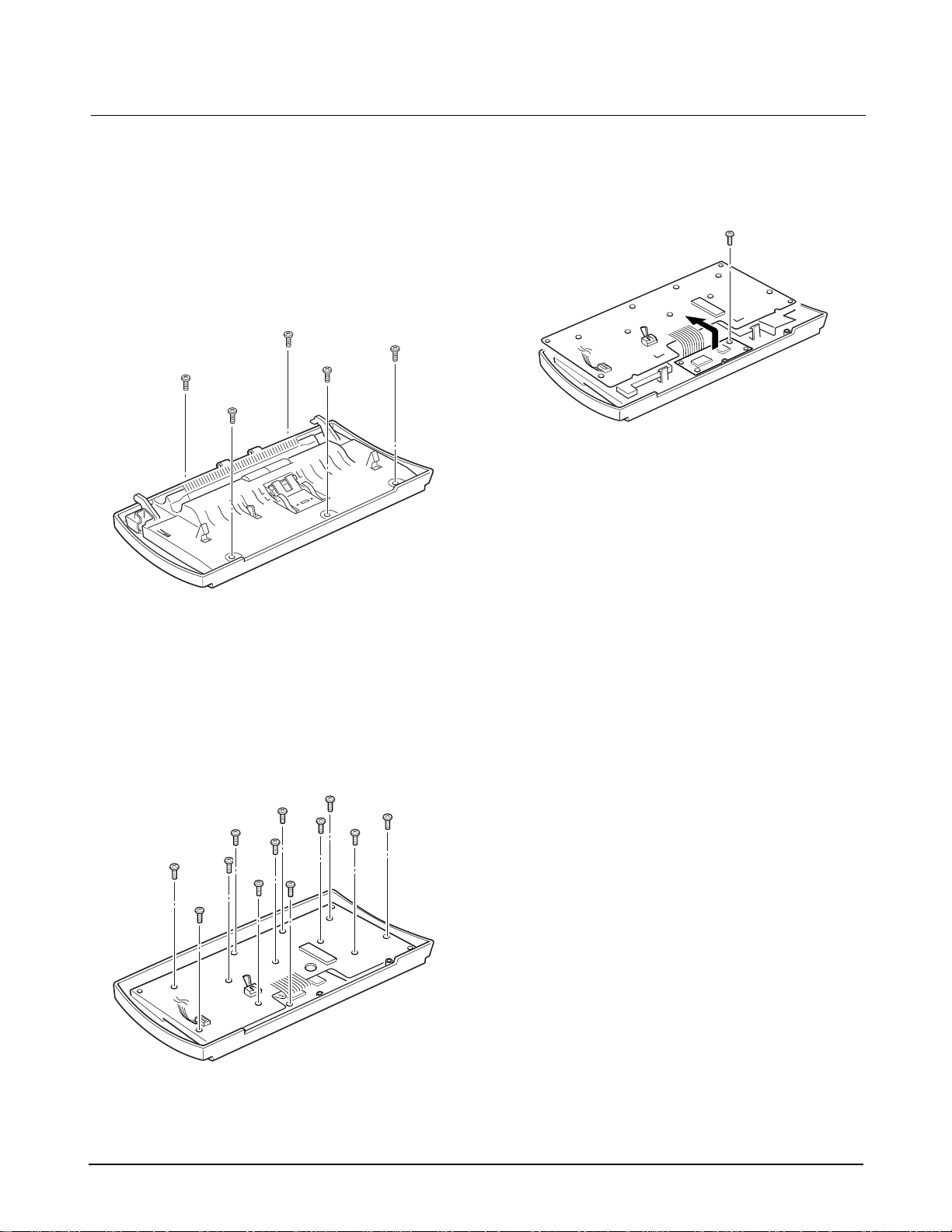
2. Remove the five screws from the OPE unit to
separate the scan upper frame as shown.
3. Remove the twelve screws as shown and take
out the PBA and the LCD.
Figure 6.21
Figure 6.22
Notes:
¥ After you remove the screws securing the PBA,
turn the PBA side up and remove the rubber
contact carefully if it is still attached into the PBA.
Be careful. Keys and rubber contacts may be
separated and you might loss any of them.
¥ When you assemble the OPE unit, make sure the
keys are in correct position so as not to make
improper contacts.
¥ When you reassemble the PBA, secure the screws
according in the order of the number printed in
the PBA.
¥ After reassembling, operate the machine to make
sure it works properly.
¥ After reassembling, make sure there is no foreign
material in the LCD.
Figure 6.23
4. Move the PBA in the direction of arrow; then
remove the one screw.
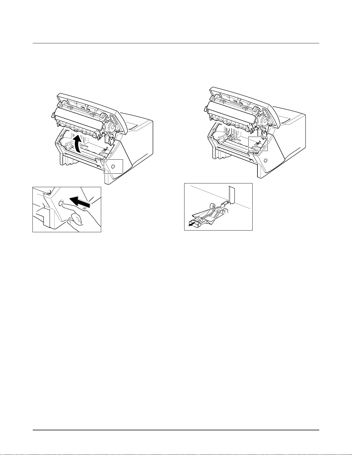
6-12 Toner Lever
1. Open the Operation unit assembly by pressing
the release button on the left side of the machine.
Disassembly and Reassembly
6-9Samsung Electronics
Figure 6.24
Figure 6.25
2. Remove the Toner lever inserted into the main
frame by squeezing both sides of the lever and
pulling it out.
Toner Lever
Disassembly and Reassembly
6-10 Samsung Electronics
2. Remove the five screws , and take out the TX
piece.
6-13 Side Covers (Left/Right)
1. Open the Control panel by hand.
3. Close the Control panel and take out the Scan
unit. Then unplug the connector from the Scan
board.
4. Remove the two screws from the colored bar.
Then remove the four screws from each Side
cover.
Figure 6.29
Figure 6.26
Figure 6.27
Figure 6.28
OPE Unit
TX piece
Disassembly and Reassembly
6-11Samsung Electronics
5. Turn the machine 90 degrees backwards to set
the back side up and release the L-shaped tab on
the bottom of the Side cover latched into the
main frame. Then take out each side cover.
6-14 Top Cover
1. Before you disassemble the Top cover, you
should remove :
♦ Side covers (See page 6-10)
2. Remove the four screws from the Top cover and
take out the cover.
Note: When you reassemble the Side covers, you
should first hook the L-shaped tabs into their
places and push the top side of the cover
firmly.
Figure 6.30
Figure 6.32
Figure 6.31
6-12 Samsung Electronics
Disassembly and Reassembly
6-15 Rear Cover
1. Before you disassemble the Rear cover, you
should remove :
♦ Side covers (See page 6-10)
♦ Top cover (See page 6-11)
2. Remove the two screws from the Rear cover.
And release the tabs latched into the main frame
and take out the Rear cover.
6-16 Speaker
1. Before you disassemble the Speaker, you should
remove :
♦ Left side cover (See page 6-10)
2. Remove the two screws securing the Speaker to
the main frame and unplug the speaker
connector. Then take out the Speaker.
Note: When you reassemble the Rear cover, hook
the tabs located on the lower end in place,
and then push the top side, so that the tabs on
the upper end are fitted in place.
Figure 6.33
Figure 6.35
Figure 6.34
Speaker
 Loading...