

Samsung Electronics 7-1
7. Maintenance & Troubleshooting
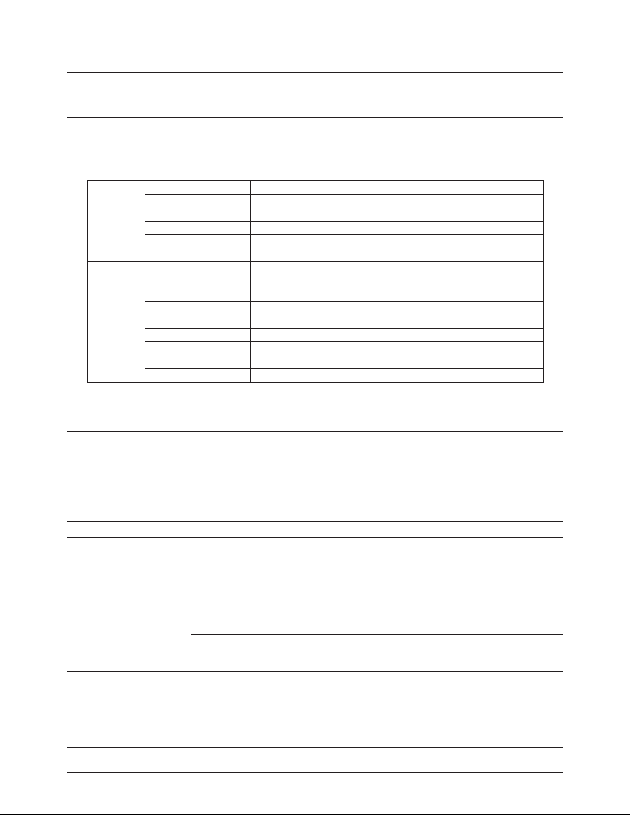
7-1 Preventative Maintenance
The cycle period outlined below is a general guideline for maintenance. The example list is for an average
usage of 50 transmitted and received documents per day. Environmental conditions and actual use will vary
these factors. The cycle period given below is for reference only.
7-2 Diagnostics
This section describes methods and procedures to isolate the cause of a malfunction in the machine. This
machine displays diagnostic information on the LCD. In addition, it can perform a series of tests that allow
the machine to observe individual machine functions.
7-2-1 Error Messages
COMPONENT
ADF Rubber
ADF Roller/Feed Roller
Roll Pinch
White Roller
CIS
Cartridge
Cleaning Felt
Pickup Roller
Feed Roller
Transfer Roller
Fuser
Driver
DRV, DEV
Frame PAD
SCANNER
PRINTER
SOLUTION
See p.6-2
See p.6-5
See p.6-7
See p.6-2
See p.6-4
See p.3-13
See p.3-15
See p.6-31
See p.6-30
See p.6-26
See p.6-20
See p.6-15
See p.6-33
CLEANING CYCLE
6 Months
6 Months
6 Months
6 Months
Error Message Description Solution
BUSY REDIAL? The machine is waiting the programmed You can press START to immediately redial,
interval to automatically redial. or STOP to cancel the redial operation.
COMM. ERROR A problem with the facsimile Try again.
communications has occurred.
INCOMPATIBLE Remote party did not have the requested Reconfirm your remote party's feature.
feature, such as a confidential
transmission or relay transmission.
It also occurs if the remote machine has
insufficient memory space to complete
the operation you are attempting
DOCUMENT JAM Loaded document has Jammed Clear the document Jam.
in the feeder
DOOR OPEN OR The top cover is not securely latched. Press down on the cover until you feel it
FUSER COVER OPEN latch securely.
The fuser cover is not securely latched. Replace the cover firmly until it clicks in place.
REPLACEMENT CYCLE
20,000 Pages
50,000 Pages
50,000 Pages
50,000 Pages
5,000 Pages
5,000 Pages
50,000 Pages
50,000 Pages
50,000 Pages
80,000 Pages
80,000 Pages
80,000 Pages
50,000 Pages

Maintenance & Troubleshooting
7-2 Samsung Electronics
Error Message Description Solution
GROUP NOT AVAILABLE You have tried to select a group location Try again, check location for group.
where only a single location number can
be used, such as when adding locations
for a multi-dial operation.
LINE ERROR Your unit cannot connect with the remote Try again. If failure persists, wait an hour
machine, or has lost contact because or so for the line to clear then try again.
of a problem on the phone line.
LOAD DOCUMENT You have attempted to set up a sending Load a document and try again.
operation with no document loaded.
MEMORY FULL The memory has become full. Either delete unnecessary documents, or
retransmit after more memory becomes
available, or split the transmission into
more than one operation.
NO ANSWER Try again.
Make sure the remote machine is OK.
TONER EMPTY or No toner cartridge in the fax machine. Install the toner cartridge in place
NO CARTRIDGE The machine stops. properly.
NO. NOT ASSIGNED The one-touch or speed dial location Dial the number manually with the
you tried to use has no number keypad, or assign the number.
assigned to it.
NO PAPER or The recording paper has run out. Load the recording paper in the paper
NO CASSETTE The printer system stops. cassette.
OVERHEAT The printer part has overheated. Your unit will automatically return to the standby
mode when it cools down to normal operating
temperature. If failure persists, call service.
PAPER JAM 0 Recording paper has jammed in paper Press STOP and clear the jam.
feeding area.
PAPER JAM 1 Recording paper has jammed inside Clear the jam.
the unit.
PAPER JAM 2 The jammed paper still remains inside Clear the jam.
the unit.
POLL CODE ERROR When setting up to poll another fax Enter the correct poll code.
machine, you have used an incorrect
poll code.
POLLING ERROR The remote fax machine you want to The remote operator should know in
poll is not ready to respond to your advance that you are polling and have their
poll. fax unit loaded with the original document.
POWER FAILURE A power failure has occurred. If there has been documents stored in
memory. Power failure report will be printed
automatically when the power is restored.
TONER EMPTY, RE- The toner is empty. The machine Replace with a new toner cartridge.
PLACE[CARTRIDGE] stops.
TONER LOW The toner is almost empty. After recording several sheets of letter
size recording paper, 'TONER EMPTY,
REPLACE[CARTRIDGE]' message appears
in the display, and the machine stops.
Replace with a new one.
WARM UP The machine is warming up and is off Wait until the machine is on-line.
PLEASE WAIT line.
The remote machine was not answered
after all the redial attempts.

Maintenance & Troubleshooting
Samsung Electronics 7-3
7-2-2 Test Mode
The test mode is used to test certain functions of
the machine. The available tests are:
¥ Pattern Test ¥ Memory Test
¥ Switch Test ¥ ROM Test
¥ CIS Test ¥ Make Shading
¥ Modem Test
To enter the Test Mode:
1. Get into the Tech mode by pressing MENU, #,
1, 9, 3, 4.
2. In Tech mode, press MENU, and one-touch 04
'SYSTEM SETUP'.
3. Scroll to the options by pressing ▼ or ▲
repeatedly until you find the one you want.
4. Press ENTER to initiate the test mode.
PATTERN TEST
There are 2 different pattern tests which can be run
to determine the condition of the LSU and the
printer components. When the LCD prompts you
to choose PATTERN 1, press ENTER. If you want
to choose PATTERN 2, press ▼ or STOP, and
press ENTER when the LCD displays 'PATTERN
2'. The test patterns include various black,
medium gray, and light gray scales. If the machine
is operating properly, each area appears even,
distinct, and with no inconsistencies in printing.
SWITCH TEST
This test checks the operation of the LCD display
and the LED indicators that interface the switches
on the operation panel.
CIS TEST
This test mode checks the condition of the Contact
Image Sensor. This is a true test of the white
reference level.
MODEM TEST
This test causes the machine to generate a
particular frequency to verify the operation of the
modem control circuits and the modem.
MEMORY TEST
This test is used for checking the Random Access
Memory (RAM) on the main PBA. If all memory is
working normally, the LCD shows TESTING OK!.
When this testing is carried out, any picture data
stored in memory is erased.
ROM TEST
This test mode will display and check the current
ROM level in your machine.
MAKE SHADING
This procedure is needed to set (make) a new
shading reference value. The reference value is
preset at factory. However, when the CIS or the
main board is replaced with new one, the
reference value must be set again.
Load the white, letter-sized paper into the feeder
and perform the test mode (MENU+ONE-TOUCH
04 'SYSTEM SETUP' in tech mode). When you
choose 'MAKE SHADING ?' option, the LCD displays
'REFERENCE [WHITE PAPER]', or 'REFERENCE
[WHITE ROLLER]'. [WHITE PAPER] message
indicates this procedure has been already
performed. The [WHITE ROLLER] message
indicates you must perform this procedure. Follow
the next steps as instructed through the LCD
window. After the shading value is newly set, the
shading value pattern is automatically printed.
Check for the waveform in the pattern. It is best
when the wave form is level. If there are many
points sharply broken, perform the Make shading
procedure several times until you get a level
waveform.
SF6500 /OK
CHECK SUM=C0, V01

Maintenance & Troubleshooting
7-4 Samsung Electronics
7-2-3 Maintenance List
A number of reports can be printed from the fax
machine within the test mode. The protocol list
and memory dump list all contain detailed
information which may be required when
contacting technical support.
To printout the protocol and memory dump lists:
1. Get into the Tech mode by pressing MENU, #,
1, 9, 3, 4.
2. In Tech mode, press MENU, and one-touch 16
'TX. CONFIRM'.
3. Press ▼ or ▲ repeatedly until you find the
Protocol Dump List. When you find
'PROTOCOL REPORT?', press ENTER.
Remote Diagnostics on the dex 825 is preformed
by a remote PC. The dex 825 has to be conditioned
o that remote PC can perform remote diagnostics.
1. Press MENU, One-touch 04 'SYSTEM SETUP'.
2. Press ▲ or ▼ until 'REMOTE DIAGNOSIS
PROTECTION ?' is displayed.
3. Press ENTER.
4. Press 1 for protection or press 2 to allow remote
diagnosis.
5. Press ENTER.
6. Press STOP to exit routine.
S NSF 61005020003380140200001302090018010000
S/R FCF FIF DATA ASCII
S CSI 2020202020202020202020202O20202020202020
S CSI 202020202020202020202022O202020220202020
R TSI 2020202020202020202020202O20202020202020
S DIS 00000000 01110111 00010111 00100010
S DIS 00000000 01110111 00010111 00100010
R DCS 00000000 01100001 00010101 00000000
R TSI 2020202020202020202020202O20202020202020
R DCS 00000000 01100001 00010101 00000000
S CFR
R MPS
S MCF
S DCN
S FTT
S NSF 61005020003380140200001302090018010000
PROTOCOL DUMP LIST AUG-20-94 06:35
Sending/Receiving
Name of signal
(Facsimile Control Field)
Facsimile Information Field
data described in hexdecmal code
FIF data described
in ASCII code
SAMPLE OF A PROTOCOL DUMP LIST
7-3 Remote Diagnostics and Control
Maintenance & Troubleshooting
7-5Samsung Electronics
Y
Y
YY
YYY
YY
YY
Y
N
N
NN
NNN
NN
N
N
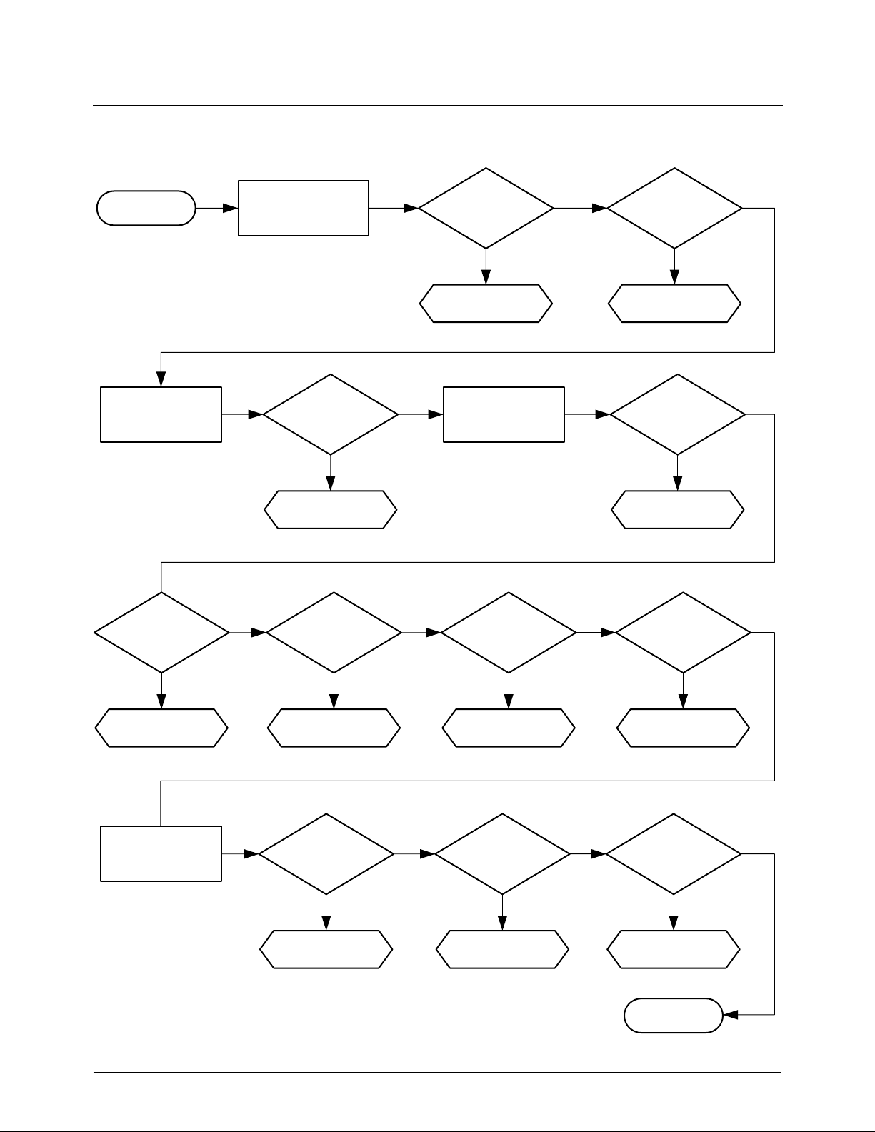
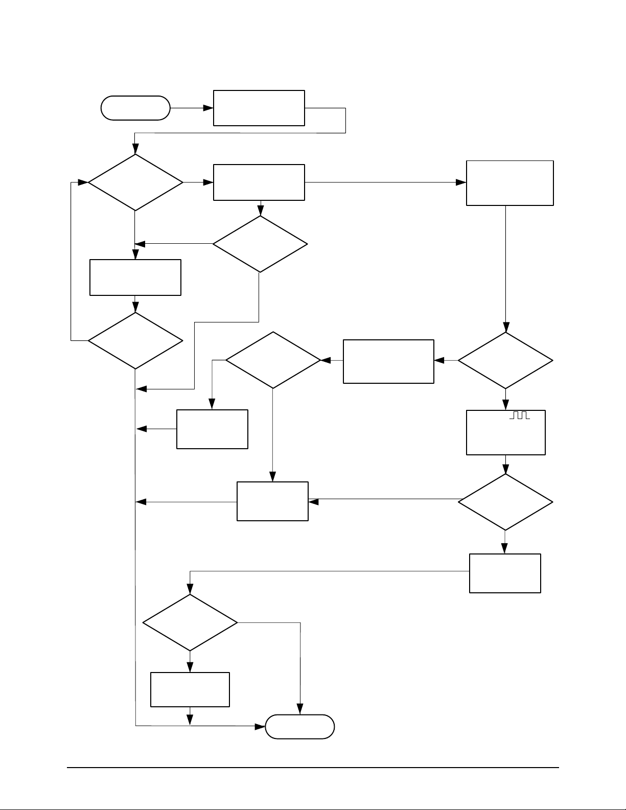
START
See chart 7-4-2
See chart 7-4-4
See chart 7-4-6
See chart 7-4-7
See chart 7-4-10 See chart 7-4-11
See chart 7-4-12
END
See chart 7-4-8 See chart 7-4-9
See chart 7-4-5
See chart 7-4-3
Plug the power cord
Load document
Copy OK?
Lift the handset
Do you hear
dial tone?
PC printing OK?
Sending OK?
Auto answer?
Manual operation?
RX OK?
Press COPY
button
CIS on?
Document fed?
LCD display
is on?
System
initialized?
7-4 Troubleshooting Flow chart
7-4-1 Overall
Maintenance & Troubleshooting
Samsung Electronics7-6
Y
N
Y
N
Y
YY Y
N
N
N
Y
Y
N
N
Y
Y
N
N
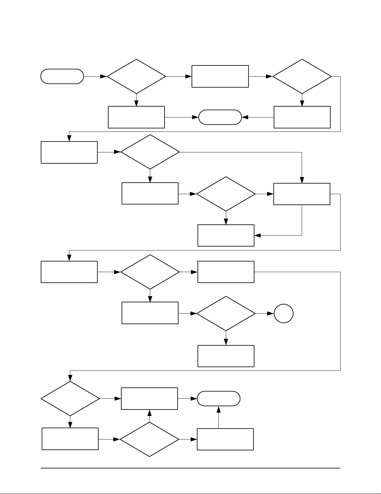
7-4-2 Malfunction of LCD Display
START
END
Power cord
connected?
Fuse OK ?
+5 V ?
+5 V ?
OK ?
Normal?
A
END
Fuse remain
good ?
Check AC voltage 220 VAC?
Notify customer
Connect as
required
1. Unplug machine
2. Check fuse
1. Replace fuse
2. Plug in machine
Check power
supply voltage
Measure voltage on
the scan b'd (CN7-1)
Measure on the
OPE b'd (CN1-1)
Replace harness
Check harness
Replace OPE b'd
and LCD module
Check harness
Replace harness
Replace power
supply
7-7Samsung Electronics
Maintenance & Troubleshooting
Y
N
Y
Y
N
N
N
Y
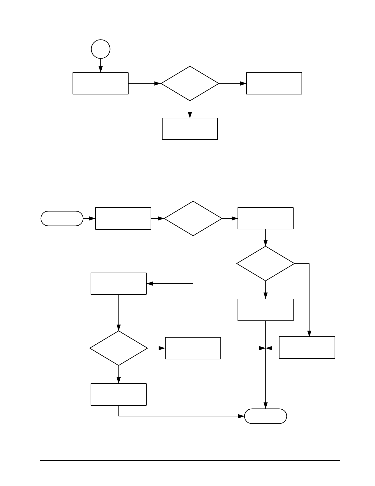
+5 V ?
A
Unplug CN6 in
the scan board
Replace OPE b'd
and LCD module
Replace the main b'd
Replace the main b'd
Check CPU-RSTO
(pin 67 of U18) in
the main board
Check system clock
(pin 50 of U18) in
the main board
Start
END
Logic 'H' ?
Replace the OPE
board
Check Vcc (+5 V)
from P1-16 to P1-18
Vcc ≥ 4.5V ?
19.6608 MHz ?
Replace power
supply
Replace the main
board
7-4-3 System Not Initialized
Maintenance & Troubleshooting
Samsung Electronics7-8
Y
Y
Y
Y
Y
Y
Y
Y
N
N
N
N
N
N
N
N
Start
END
'DOCUMENT
READY' displayed ?
Key in ?
Document fed ?
Normal?
Logic 'H'?
Document fed?
+24 V?
Check the OPE
MICOM
Check LCD display
when document
is loading
Replace the
OPE board
Replace mother
b'd
Check
motor pulse (P1-9,
10, 11, 12) in the
main board
5V
0V
Check +24V motor
enable
(P2-27) in
the main board
Replace the
main b'd
Replace the
motor ass'y
Replace the
scan b'd
Check +24V from
P19, 20 of CN7 in
the scan b'd
7-4-4 Malfunction on Document Feeding

7-9Samsung Electronics
Maintenance & Troubleshooting
Y
N
N
N
N
Y
Y
Y
7-4-5 CIS LED Not Lit
START
See chart 7-4-4
Load document in
feeder
Works properly?
Normal?
+5 V ?
CIS LED lights
Check +5V, +12V
(P1-16, 17, 18, P1-1
in the main b'd)
Replace the power
supply
Replace CIS
Replace the main b'd
Check PIN27 of
U25
END
Press the COPY
button
Document fed?

Maintenance & Troubleshooting
Samsung Electronics7-10
Y
Y
N
N
N
N
N
N
Y
Y
Y
Y
Y
N
7-4-6 Malfunction on Copy
START
See chart7-4-4
See chart 7-4-5
1
1
Load document in
feeder
Replace CIS
Replace the main b'd
Replace the
scan b'd
Check harness
Replace the
power supply
Replace the
harness
Measure
LED +12V on
scan b'd (CN 3-9)
+12 V?
Good?
Copy produced?
Press the COPY
button
Document fed?
CIS LED on?
Copy works
properly?
Normal?
Check
CIS clock (P2-16)
in the main board
5V
0V

7-11Samsung Electronics
Maintenance & Troubleshooting
Y
Y
Y
Y
N
N
N
N
1
Run the printer test
Run the CIS test
Replace the CIS
Replace the main b'd
END
Good copy quality?
Normal?
Good copy quality?
Good printer
quality?

Maintenance & Troubleshooting
Samsung Electronics7-12
Y
Y
Y
N
N
N
7-4-7 Malfunction in Auto Answer
START
END
Call the machine
from another phone
Check ring signal
on P4-8 in main b'd
Check ring signal on
U1-25, 28 in LIU b'd
Replace the LIU b'd
Replace the main b'd
Auto answer?
Normal?
5V
?
0V

7-13Samsung Electronics
Maintenance & Troubleshooting
Y
Y
N
N
N
Y
7-4-8 Malfunction in Manual Receiving
START
END
Press OHD and
press START
Check signal in
P4-12 in main b'd
Replace the main b'd
Replace the LIU b'd
Replace the flat
cable
Check control
signal(P1-13, 14) in
the LIU b'd
Goes on line?
Logic 'L'?
Logic 'L'?

Maintenance & Troubleshooting
Samsung Electronics7-14
Y
Y
Y
Y
N
N
N
N
7-4-9 Malfunction in Automatic Receiving
START
See chart 7-4-7
END
END
Call the machine
from another phone
Check the
telephone line
Check Tx/Rx signal
in P1-4, P1-7 in the
LIU b'd
Replace the main b'd
Auto answer?
Normal?
Normal?
Notify to customer
Replace the LIU b'd
Receive data?

7-15Samsung Electronics
Maintenance & Troubleshooting
Y
Y
Y
N
N
N
7-4-10 Malfunction in Transmission
START
See chart 7-4-4
END
Load document in
feeder
Call the receiving
machine
Press the START
button
Replace the LIU b'd
Replace the main b'd
Document fed?
The document
sends out?
Sending works
properly?

Maintenance & Troubleshooting
Samsung Electronics7-16
Y
Y
N
N
Y
N
N
N
Y
Y
Y
N
7-4-11 Malfunction in PC Printing
START
END
Print text file in windows version editor
Run MFP825 control program
Run 'Print test page'
Setup MFP825 Printer driver.
Check application S/W.
Replace centronics cable.
Install MFP board correctly.
Replace MFP board.
Replace Main b'd
Check bi-directional centronics cable
Make sure the MFP board is
installed properly.
Printer self test
Works properly?
Works properly?
Works properly?
OK?
OK?
OK?

7-17Samsung Electronics
Maintenance & Troubleshooting
Does the toner
adhere to magnetic roller
of developer unit ?
Are the sealing
tapes on the toner cartridge
removed ?
N
N
Y
Y
N
Remove the
sealing tapes.
N
Y
N
Y
Y
A
B
START
Is there any
image printed ?
Does the cartridge
work normally ?
Does the trouble
occur even with another
cartridge ?
Check the HVPS and replace
the HVPS necessary
Replace the cartridge.
7-4-12 No Paper of the Image (All white printed)

Maintenance & Troubleshooting
Samsung Electronics7-18
N
Y
N
Y
N
Y
A
B
Is the transfer roller O.K ?
Does the trouble occur even with
another LSU unit ?
Does the trouble occur even
with another toner cartridge ?
Check the developer driver unit and
then replace it if necessary. See page 6-27.
Replace the toner cartridge.
Check the LSU unit and
then replace it if necessary.
Replace the transfer roller.
Replace the HVPS or connect the
harness properly.
Nomal voltage in HVPS ?
Its wiring harness O.K ?

Maintenance & Troubleshooting
7-19Samsung Electronics
N
N
Y
Y
N
Y
N
Y
START
Does the trouble occur even with
another cartridge ?
Nomal voltage in HVPS ?
Its wiring harness O.K ?
Is the development bias connector
of cartridge O.K ?
Check LSU unit and then
replace it if necessary.
Replace the HVPS or connect
the wiring harness properly.
Replace the HVPS or connect
the wiring harness properly.
Replace the transfer unit. See page 6-26.
Replace the cartridge. See page 3-14.
Is the transfer unit O.K ?
7-4-13 Pale/Weak Image Quality
7-4-14 High Background Density (Toner in the background areas)
N
START
Does the trouble occur even with
another cartridge ?
Check HVPS and replace it if necessary.
Replace the cartridge.

Maintenance & Troubleshooting
Samsung Electronics7-20
7-4-15 Uneven Density
N
Y
N
Y
START
Is the transfer unit O.K ?
Check the LSU unit and then
replace it if necessary.
Check the transfer roller or replace
the transfer unit.
Replace the cartridge.
Does the trouble occur even with
another cartridge ?
7-4-16 All Black Printed
N
N
Y
Y
N
Y
START
Is the drum installed properly ?
Is charge wring harness in HVPS O.K ?
Check the LSU unit and then replace
it if necessary.
Connect the harness properly or
replace it.
N
Y
Does the trouble occur even with
anther HVPS ?
Replace the HVPS.
Replace the cartridge.
Replace drum properly.
Does the trouble occur even with
another cartridge ?

Maintenance & Troubleshooting
7-21Samsung Electronics
7-4-17 Black Vertical Line
N
Y
N
Y
Occured during
receiving.
Check the LSU unit and then replace
it if necessary.
Replace the cartridge.
Trouble on the remote fax machine.
Does the trouble occur even
with another cartridge ?
N
Y
Replace the fuser unit.
Is the heat roller of the
fuser unit damaged ?
Pattern test O.K ?
N
Y
N
Y
Occured during
copying.
Check the LSU unit and then replace
it if necessary.
Replace the cartridge.
Check CIS or white roller and
then replace it if necessary.
Does the trouble occur even
with another cartridge ?
N
Y
Replace the fuser unit.
Is the heat roller of the
fuser unit damaged ?
Pattern test O.K ?

Maintenance & Troubleshooting
Samsung Electronics7-22
7-4-19 White Vertical Line
N
Y
START
Is there enough toner in the
developer unit ?
Check the LSU unit and then replace
it if necessary.
Y
N
Is the heat roller of the fuser unit
damaged ?
Replace fuser unit.
Replace the cartridge.
7-4-18 Black Horizontal Line
N
N
Y
Y
N
Y
START
Is the heat roller of the fuser unit
damaged ?
Check the LSU unit and then replace
it if necessary.
Replace the fuser unit.
Replace the fuser felt.
Replace the cartridge.
Does the trouble occur even with
another fuser felt ?
Does the trouble occur even with
another cartridge ?

Maintenance & Troubleshooting
7-23Samsung Electronics
7-4-20 All Black Printed
N
Y
N
Y
Occured during
receiving.
Check the LSU unit and then replace
it if necessary.
Replace the cartridge.
Trouble on the remote fax machine.
Does the trouble occur even
with another cartridge ?
Y
N
Replace the HVPS or connect
the harness properly.
Nomal voltage in HVPS ?
Its wiring harness O.K ?
Pattern test O.K ?
N
Y
N
Y
Occured during
copying.
Check the LSU unit and then replace
it if necessary.
Check CIS and then replace
it if necessary.
Does the trouble occur even
with another cartridge ?
Y
N
Pattern test O.K ?
Nomal voltage in HVPS ?
Its wiring harness O.K ?
Replace the cartridge.
Replace the HVPS or connect
the harness properly.

Maintenance & Troubleshooting
Samsung Electronics7-24
7-4-21 Avoid the Image
Y
N
START
Nomal voltage in HVPS ?
Its wiring harness O.K ?
Check the transfer roller and
then replace it if necessary.
Replace the HVPS or
connect the harness properly.

Maintenance & Troubleshooting
7-25Samsung Electronics
Y
Y
N
N
N
N
N
Y
Y
Y
START
Motor
driving ?
+5V ?
Logic 'L' ?
Check
motor pulse (CN2-1.2.3.4)
in the 2'nd cassette b'd
Normal ?
Replace 2'nd
cassette b'd
Replace motor ass'y
END
Replace main b'd
0V ?
Check SCFCLUTCH on the 2'nd
cassette b'd (CN2-6)
Measure voltage on
the 2'nd cassette b'd
(CN1-1)
Replace 2'nd
cassette b'd
Check harness and
replace harness
Check SCF-START
on the 2'nd cassette
b'd (CN1-3)
Replace solenoid
24V
0V
7-4-22 Second Paper Cassette (Option)
MALFUNCTION ON PAPER FEEDING
 Loading...