

Samsung SF5600 Specifications

CHAPTER 3
Theory of Operation

3-1
Chapter 3 THEORY OF OPERATION
3.1 FUNCTION BLOCK DIAGRAMS
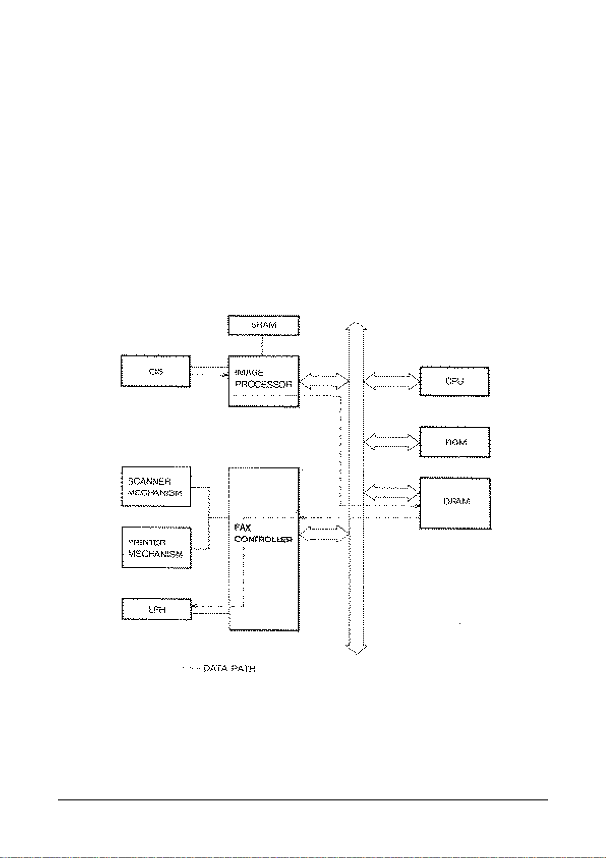
3.1.1 MAIN BLOCK DIAGRAM
3-2
3.1.2 COPY OPERATION
When a document is inserted in ADF, the leading edge of the original document is detected by the
document detect sensor and the information is transmitted to the Main PBA via micom in OPE PBA to
energize the scanner motor and pull the first page into the ADF. The scanner motor will continue to run
until the document contacts the scan sensor. Then the scanner motor will stop and LCD will display
"DOCUMENT READY". The light and dark of each line is converted to a corresponding electrical voltage by
the C19. This signal is fed to the SDIP of the Main PBA as serial data. SDIP carries out the serial data to
parallel conversion of the binary image and transfers the image to the page memory area where it is stored.
The printing will start after the specified number of pages are stored in page memory. NS32FX200 of the
Main PBA transfers the stored data in page memory to the LPH. Parallel to serial conversion of the word
formatted data is done in the NS32FX200. The LPH is turned on for each black dot and off for each white
dot. This produces a latent image on the charged OPC drum. The latent image on the drum is developed
when it passes by the brush of toner cartridge. As the image is rotated further it comes in contact with the
plain paper. The image is transferred to the paper by the transfer corona which attracts the toner from the
drum to the paper. Next the toner is fused to the paper by means of heat and pressure from the fuser. The
copy is then moved to the exit tray.
3-3
3.1.3 G3 TRANSMISSION
The CIS picks up one line of image 1728 pels. The signal is then sent to the SDIP for digital processing. This
processed data is paralleled out on the data bus and dumped into the T.4 to file buffer (MMR). After the
data stored to T.4 to file buffer encodes, it is transfer to file to T.4 buffer (MR, MH, MMR) for transmission.
The NS32FX200 generates a vector interrupt to the CPU to tell it to be ready for transmitting the image data.
The NS32FX200 outputs the serial bit stream at sigma delta oversampling rate to the analog transmitter of
the AFE. The serial bit stream is fed to a 7 bit D/A converter. This D/A converter is implemented by an
analog switch, which selects either + 5V or -5V inputs. These voltages are filtered by an RC low pass filter to
filter supply noise. The D/A output is filtered by three pole LPF with unit gain to attenuate the out-of-band
quantization noise. The output of the LPF passes to the transformer through a 3 dB gain amplifier.
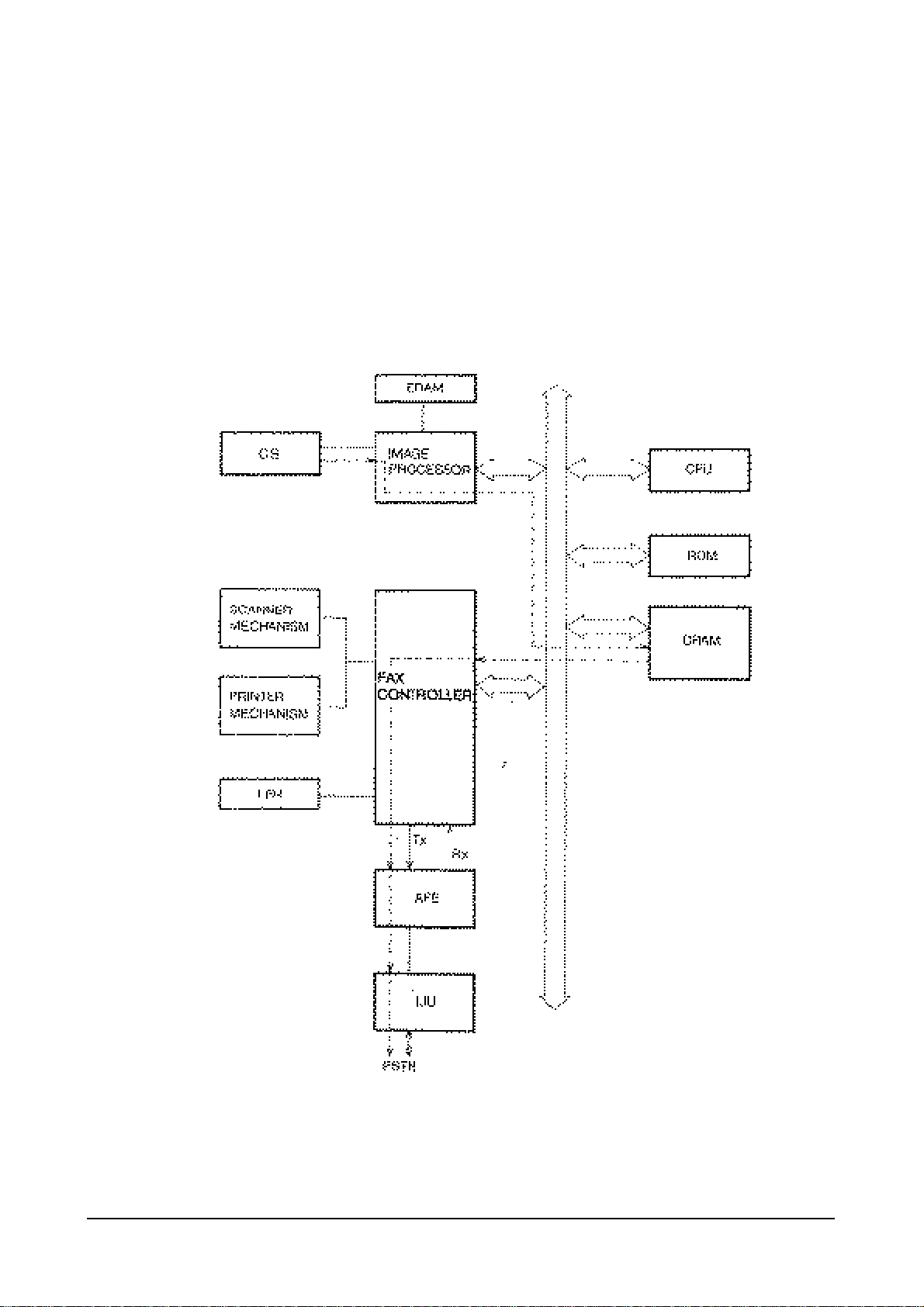
Transmission Block Diagram
3-4
3.1.4 G3 RECEPTION
The reception analog circuit obtains its analog input signal from the transmission. The signal passes through
a buffer, amplifier, and then enters the sigma delta second order loop. The amplifier has two gain levels. The
-9dB gain is obtained when the training check is passed from the sending machine.
The sigma delta second order loop contains two integrators and a comparator. The comparator output is the
SDIN input to the one-chip sigma delta part of the NS32FX200.
SDIN is sampled one-chip at over sampling rate, is passed to the digital filters and returns to SDFDBK pin.
This feedback enters a 7 bit D/A converter and passes through the first integrator unit. If the receive FIFO is
filled with data, the NS32FX200 generates interrupts to the CPU. The CPU stores the coded data to T.4 to file
buffer and converts to the MMR data format.
The MMR data is regenerated to the bit map pixel data, then CPU starts storing this data to the printer
buffer. After the storing of one page bit map data is completely finished, this data is sent to the LPH via
DMA operation of the NS32FX200.
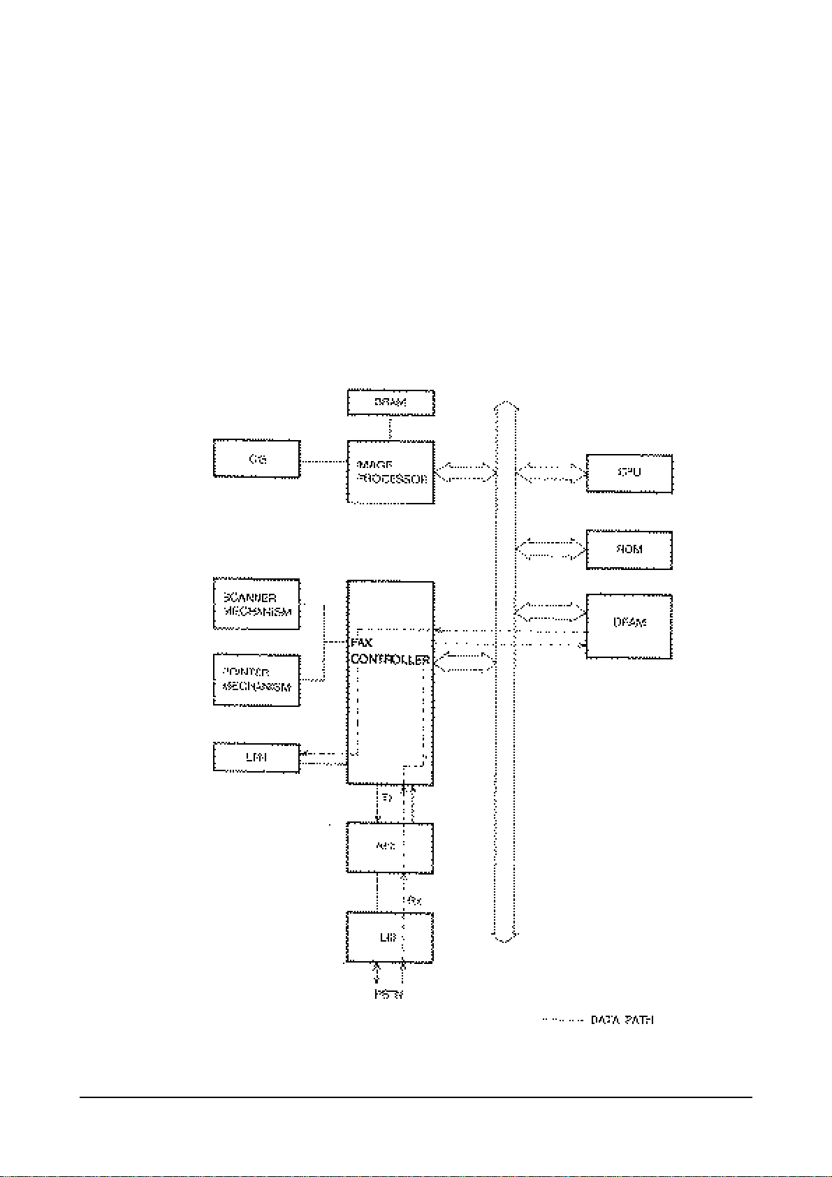
Reception Block Diagram
 Loading...